EP2955144A1 - Control panel for an elevator - Google Patents
Control panel for an elevator Download PDFInfo
- Publication number
- EP2955144A1 EP2955144A1 EP15169241.5A EP15169241A EP2955144A1 EP 2955144 A1 EP2955144 A1 EP 2955144A1 EP 15169241 A EP15169241 A EP 15169241A EP 2955144 A1 EP2955144 A1 EP 2955144A1
- Authority
- EP
- European Patent Office
- Prior art keywords
- control panel
- door
- actuator
- latch
- key
- Prior art date
- Legal status (The legal status is an assumption and is not a legal conclusion. Google has not performed a legal analysis and makes no representation as to the accuracy of the status listed.)
- Granted
Links
Images



Classifications
-
- B—PERFORMING OPERATIONS; TRANSPORTING
- B66—HOISTING; LIFTING; HAULING
- B66B—ELEVATORS; ESCALATORS OR MOVING WALKWAYS
- B66B11/00—Main component parts of lifts in, or associated with, buildings or other structures
- B66B11/001—Arrangement of controller, e.g. location
-
- B—PERFORMING OPERATIONS; TRANSPORTING
- B66—HOISTING; LIFTING; HAULING
- B66B—ELEVATORS; ESCALATORS OR MOVING WALKWAYS
- B66B1/00—Control systems of elevators in general
- B66B1/34—Details, e.g. call counting devices, data transmission from car to control system, devices giving information to the control system
- B66B1/46—Adaptations of switches or switchgear
- B66B1/461—Adaptations of switches or switchgear characterised by their shape or profile
- B66B1/465—Adaptations of switches or switchgear characterised by their shape or profile being resistant to damage
-
- B—PERFORMING OPERATIONS; TRANSPORTING
- B66—HOISTING; LIFTING; HAULING
- B66B—ELEVATORS; ESCALATORS OR MOVING WALKWAYS
- B66B1/00—Control systems of elevators in general
- B66B1/34—Details, e.g. call counting devices, data transmission from car to control system, devices giving information to the control system
- B66B1/3415—Control system configuration and the data transmission or communication within the control system
- B66B1/3423—Control system configuration, i.e. lay-out
-
- B—PERFORMING OPERATIONS; TRANSPORTING
- B66—HOISTING; LIFTING; HAULING
- B66B—ELEVATORS; ESCALATORS OR MOVING WALKWAYS
- B66B13/00—Doors, gates, or other apparatus controlling access to, or exit from, cages or lift well landings
- B66B13/30—Constructional features of doors or gates
- B66B13/306—Details of door jambs
-
- E—FIXED CONSTRUCTIONS
- E05—LOCKS; KEYS; WINDOW OR DOOR FITTINGS; SAFES
- E05B—LOCKS; ACCESSORIES THEREFOR; HANDCUFFS
- E05B19/00—Keys; Accessories therefor
- E05B19/14—Double or multiple keys, e.g. with two or more bows or bits
-
- E—FIXED CONSTRUCTIONS
- E05—LOCKS; KEYS; WINDOW OR DOOR FITTINGS; SAFES
- E05B—LOCKS; ACCESSORIES THEREFOR; HANDCUFFS
- E05B47/00—Operating or controlling locks or other fastening devices by electric or magnetic means
- E05B47/0001—Operating or controlling locks or other fastening devices by electric or magnetic means with electric actuators; Constructional features thereof
-
- E—FIXED CONSTRUCTIONS
- E05—LOCKS; KEYS; WINDOW OR DOOR FITTINGS; SAFES
- E05C—BOLTS OR FASTENING DEVICES FOR WINGS, SPECIALLY FOR DOORS OR WINDOWS
- E05C9/00—Arrangements of simultaneously actuated bolts or other securing devices at well-separated positions on the same wing
- E05C9/02—Arrangements of simultaneously actuated bolts or other securing devices at well-separated positions on the same wing with one sliding bar for fastening when moved in one direction and unfastening when moved in opposite direction; with two sliding bars moved in the same direction when fastening or unfastening
Definitions
- the invention relates to the structures of control panels for an elevator.
- An elevator comprises various electrical components, such as electronics cards, relays, switches, safety devices, et cetera, with which the operation of the elevator is controlled.
- a large proportion of the electrical components of an elevator are disposed in a separate control panel, from where control cables and current supply cables travel to different parts of the elevator system.
- the main switch of the elevator and also the elevator control electronics, inter alia, are usually disposed in the control panel.
- Manually-operated devices can also be disposed in the control panel, with which devices the elevator is operated during servicing and maintenance and also when saving passengers stuck in the elevator car in a fault situation.
- the control panel is conventionally situated in a separate machine room, to which access is restricted.
- a great many elevators do not have a separate machine room.
- the control panel can be situated e.g. in the elevator hoistway or on a stopping floor of the elevator outside the elevator hoistway. In this case the control panel is usually locked, so that unauthorized persons cannot gain access to the components in the control panel.
- control panels on a floor level and also, on the other hand, in the elevator hoistway, can be a target for vandalism.
- the locking of the control panel is not necessarily sufficiently effective to prevent unauthorized opening of the control panel.
- the actual lock of the control panel can itself become a target for vandalism; for example, attempts may be made to insert foreign objects into the keyhole that is in the control panel.
- One aim of the invention is to disclose an elevator control panel that is better protected against vandalism than what is known in the art.
- One aspect of the invention is an elevator control panel comprising a base, side walls, a door and also a lock mechanism for locking and opening the door.
- the lock mechanism comprises an arresting means, which is adapted to be movable between a locking position and a releasing position, and also an electrically controllable actuator connected to the arresting means, the actuator being adapted to move the arresting means in response to a wireless control signal.
- the lock can be opened and closed electrically with the actuator by sending a wireless control signal for controlling the actuator. Thanks to the wireless electronic control, a control panel with its locking mechanisms can be designed without a conventional keyhole in the control panel door.
- control panel is fitted into the doorframe of a landing door, and the outer surface of the control panel forms an unbroken finished surface as a part of the doorframe when installed on a stopping floor. In this case a person near the landing door does not even necessarily notice the control panel in the doorframe of the landing door.
- a second aspect of the invention is a key for locking and opening the lock mechanism of the elevator control panel presented in the description.
- control panel includes electronics configured to control the movement of the elevator car.
- control panel includes an inspection drive connection, via which a serviceman can give a control command for performing servicing procedures and/or rescue procedures.
- the lock mechanism comprises a manually-operated latch engaging with the actuator, which latch is adapted in the first position to prevent and in the second position to allow movement of the arresting means towards the releasing position.
- the control panel has a spring, the force brought about by which tries to displace the arresting means towards the releasing position.
- the arresting means is thus adapted so that the gravity being exerted on the arresting means tries to displace the arresting means towards the releasing position.
- the arresting means can be displaced by means of a spring/gravity into the releasing position, in which case opening of the door is also possible in situations in which electricity is not available for operating the actuator (e.g.
- the axis of rotation of the latch is in the direction of the surface of the control panel door.
- a flat key can be pushed into the control panel from the narrow gap in the door or in the edge of the door, and the latch/locking of the door can also be opened by turning the key in the direction of the gap.
- the latch is turnable.
- the key comprises a counterpart engaging with the manually-operated latch, around the axis of rotation of the latch, as well as a handle, by turning from which handle the latch can be turned around its axis of rotation. In this case the latch can be released and the door can be opened by hand by turning the key.
- the arresting means is an elongated rail traveling along a side wall of the panel, the rail having detents in the longitudinal direction that are adapted to engage with counterparts on the door.
- the control panel is elongated, in which case it can be easily situated e.g. in the doorframe of a landing door. In this case the door can be locked by means of the consecutive detents of the elongated rail/on the rail for essentially the whole of its length, which makes opening the control panel without a key difficult.
- control panel has an elongated, sloping wall part.
- the rail is adapted to travel along the outer surface of the sloping wall part, and the actuator is fitted into the space between the sloping wall part and the door.
- the sloping wall part is situated between the base and the second side wall, and the door continues from the hinge point over the doorway bending to be in the direction of the second wall part and over the second wall part onwards bending to be in the direction of the base in such a way that a space for the actuator remains between the door and the sloping wall part. In this case space is created for the actuator outside the control panel but under the cover and sheltered from vandalism. Since the actuator is outside the control panel, the components of the control panel are also better sheltered when operating the actuator.
- the edge of the first side wall on the door side bends outwards, and the edge of the door bends correspondingly inwards in such a way that the bends form a detachable hinging between the first side wall and the door.
- a simple hinge mechanism can be formed, by means of which the door can be turned in a small space and the opened door can also be easily detached from the control panel during working.
- the counterparts of the detents are disposed on the inside surface of the door in the part in the direction of its base. In this case when locking the door the detents wedge against the counterparts, and a force from the effect of the detents is exerted on the door, the force pressing the door against the doorway compressing the contact between the door and the doorway.
- the actuator comprises an electronic control unit, which comprises an input circuit for a wireless control signal.
- the input circuit comprises a plurality of magnetic sensors disposed at a predefined position in relation to each other, and the control unit is configured to form a control command for the actuator for moving the arresting means when the measurement results being received from all the magnetic sensors correspond to predefined values.
- the means for forming a wireless control signal comprise a plurality of permanent magnets fitted so as to be interpositioned to correspond to the magnetic sensors of the description. This means that a position coding has been made with the magnetic sensors, in which case opening of the door requires taking a key that is position-coded in the same way to the correct location in the proximity of the electronic control unit.
- the actuator is a spindle motor.
- a spindle motor is that sufficient force for moving the rail/detents with sufficient reliability is obtained with a small-sized motor.
- control panel comprises an end doorframe, and between the end doorframe and the door is a gap for receiving a key.
- a flat key can be taken from the gap to the correct location in the proximity of the electronic control unit, and a separate keyhole does not need to be made in the cabinet door.
- the key comprises means for forming a wireless control signal.
- the key can include a radio transmitter, which sends an electromagnetic signal that is read by a receiver in the electronic control unit.
- an electromagnetic signal e.g. an ultrasound signal can also be used.
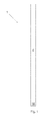
- Fig. 1 presents an elongated control panel 1, which is intended to be disposed in the side doorframe of a landing door of a machine-roomless elevator.
- a landing door means a door that closes access from a floor level into the elevator hoistway. Elevator passengers are able to transfer into the elevator car, and to leave the elevator car, via a landing door when the elevator car is situated at a floor level at the point of the landing door. At other times a landing door can be opened with a special service key, in which case a serviceman is able to go into the elevator hoistway via the open landing door.
- the door 4 of the control panel of Fig. 1 does not have a separate keyhole, but instead the outer surface of the control panel forms an unbroken finished surface as a part of the doorframe. Consequently, the control panel is better protected against vandalism.
- the unbroken outer surface also improves the visual appearance of the doorframe of a landing door.
- the new type of control panel according to Fig. 1 has become possible thanks to a new type of locking mechanism that is presented below in more detail.
- Fig. 2 presents a rear view of the control panel of Fig. 1.
- Fig. 3 diagrammatically presents the control panel of Fig. 1 as viewed from below.
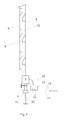
- Fig. 4 diagrammatically presents the locking mechanism of the control panel of Figs. 1 - 3.
- the control panel comprises a base 2, side walls 3', 3", a door 4 and also a lock mechanism for locking and opening the door.
- the edge of the first side wall 3' on the door side bends outwards, and the edge of the door 4 bends correspondingly inwards in such a way that the bends 5A, 5B form a detachable hinging between the first side wall 3' and the door 4.
- a simple hinge mechanism is formed from the bends of the door 5B and of the side wall 5A, by means of which mechanism the door can be turned in a small space and the opened door can also be easily detached from the control panel 1 during working.
- the control panel 1 has an elongated, sloping wall part 3"', which is situated between the base 2 and the second side wall 3".
- the lock mechanism comprises an elongated steel rail 6 traveling along the pins 25 that are on the outer surface of the sloping wall part 3"', which steel rail is moved in the vertical direction with the spindle motor 7 fixed to the steel rail 6.
- In the steel rail 6 are grooves 24 that move along the pins 25 when moving the steel rail 6 in the vertical direction.
- the door 4 continues from the hinge point 5A, 5B over the doorway 14 bending to be in the direction of the second wall part 3" and over the second wall part 3" onwards bending 4' to be in the direction of the base in such a way that a space 13 remains for the spindle motor 7 between the door and the sloping wall part 3"'.
- wedge-shaped detents 9 Fixed to the steel rail 6 in the longitudinal direction are wedge-shaped detents 9, which are adapted to press against the wedge-shaped counterparts 10 in the door when the steel rail 6 is moved upwards.
- the counterparts 10 of the detents are disposed on the inside surface of the door, in the part 4' in the direction of its base.
- the upward-moving detents 9 wedge against the counterparts 10 and lock the door.
- the door 4 is pressed tightly against the doorway 14, and the components of the control panel 1 are sheltered from dirt and moisture.
- the door is opened by moving the steel rail 6/detents 9 downwards in such a way that the detents 9 again separate from the counterparts 10.
- the spindle motor 7 is controlled with an electronic control unit 12, which is situated in the same space as the spindle motor 7.
- the electronic control unit 12 is, however, situated in the inside space 21 of the control panel, in which case it is better protected from moisture and dirt.
- the electronic control unit 12 has three reed switches 16 on a circuit card, which are disposed at a predefined position in relation to each other.
- the electronic control unit 12 is configured to form a control command for the spindle motor 7 to move the steel rail 6 when all three reed switches 16 are controlled into a conducting state. This occurs by taking the key board 17 next to the circuit card for the reed switches 16.
- On the key board 17 are three permanent magnets, the interpositioning of which corresponds to the interpositioning of the reed switches 16 on the circuit card (see Fig. 5).
- the permanent magnets 15 on the key board are situated next to the reed switches 16, the magnetic field of each permanent magnet 15 controls the contact of the reed switch 16 in the immediate proximity of it to be conducting.
- a spindle motor 7 is an actuator, the movement of a rotating electric motor in which actuator is converted into linear movement of the spindle.
- the control method of the spindle motor 7 is in itself known in the art, and it is not presented here in more detail.
- the lock mechanism of the control panel 1 also comprises a manually-operated latch. By turning the latch the locking of the door 4 can be opened also in a situation in which electricity is not available for the spindle motor 7.
- the latch comprises a rotating bolt or stud bolt 11, the head of which fits into the jaws 19 in the key 17.
- the latch also comprises a stationary pin 8, which presses into the groove 23 in the bolt 11.
- the bolt 11 is asymmetrical in relation to the axis of rotation in such a way that the pin 8 exits from the groove 23 when turning the bolt, see Fig. 6.
- the lock mechanism also comprises a tension spring 22, which pulls the bolt 11 downwards.
- the latch opens and the tension spring 22 pulls the bolt 11, the spindle motor 7 and at the same time the steel rail 6 downwards, in which case the locking of the control panel opens.
- the bolt is disposed in such a way that the jaws of the key 17 meet with the head of the bolt 11, when the latch is closed, when the key is pushed into the space 13 below the covers 4 from the gap between the door 4 and the end doorframe 18.
- the latch When the control panel has been opened from the manually-operated latch, the latch must be reset before the electrical opening mechanism can again be used. This occurs by first lifting the bolt 11/spindle motor 7 against the pulling force of the spring 22 back to the original position and after this by rotating the bolt 11 in such a way that the pin 8 presses back into the groove 23 that is in the bolt 11.
- control panel is presented as a part of the doorframe of a landing door.
- control panel is disposed in the elevator hoistway, where it can be fixed e.g. to the wall of the elevator hoistway, to a guide rail of the car or counterweight, or into connection with the electric drive of the elevator.
- magnetoresistive sensors can be used as magnetic sensors 16.
- the number of magnetic sensors can vary; in principle, there can be 2 - N units of them instead of three. What is essential is that the number of magnetic sensors and their interpositioning is consistent with the permanent magnets 15 that are on the key.
- a spindle motor 7 e.g. a solenoid, step motor or corresponding drive device bringing about a linear movement from the effect of electric power can be used in the actuator.
Landscapes
- Engineering & Computer Science (AREA)
- Automation & Control Theory (AREA)
- Mechanical Engineering (AREA)
- Computer Networks & Wireless Communication (AREA)
- Civil Engineering (AREA)
- Structural Engineering (AREA)
- Elevator Door Apparatuses (AREA)
- Lock And Its Accessories (AREA)
Abstract
Description
- The invention relates to the structures of control panels for an elevator.
- An elevator comprises various electrical components, such as electronics cards, relays, switches, safety devices, et cetera, with which the operation of the elevator is controlled.
- A large proportion of the electrical components of an elevator are disposed in a separate control panel, from where control cables and current supply cables travel to different parts of the elevator system. The main switch of the elevator and also the elevator control electronics, inter alia, are usually disposed in the control panel. Manually-operated devices can also be disposed in the control panel, with which devices the elevator is operated during servicing and maintenance and also when saving passengers stuck in the elevator car in a fault situation.
- The control panel is conventionally situated in a separate machine room, to which access is restricted. Nowadays, however, a great many elevators do not have a separate machine room. In these so-called machine-roomless elevators the control panel can be situated e.g. in the elevator hoistway or on a stopping floor of the elevator outside the elevator hoistway. In this case the control panel is usually locked, so that unauthorized persons cannot gain access to the components in the control panel.
- One problem is that control panels on a floor level and also, on the other hand, in the elevator hoistway, can be a target for vandalism. The locking of the control panel is not necessarily sufficiently effective to prevent unauthorized opening of the control panel. In addition, the actual lock of the control panel can itself become a target for vandalism; for example, attempts may be made to insert foreign objects into the keyhole that is in the control panel.
- One aim of the invention is to disclose an elevator control panel that is better protected against vandalism than what is known in the art.
- To achieve this aim the invention discloses an elevator control panel according to claim 1 and also a key according to
claim 9. The preferred embodiments of the invention are described in the dependent claims. Some inventive embodiments and inventive combinations of the various embodiments are also presented in the descriptive section and in the drawings of the present application. - One aspect of the invention is an elevator control panel comprising a base, side walls, a door and also a lock mechanism for locking and opening the door. The lock mechanism comprises an arresting means, which is adapted to be movable between a locking position and a releasing position, and also an electrically controllable actuator connected to the arresting means, the actuator being adapted to move the arresting means in response to a wireless control signal. In this case the lock can be opened and closed electrically with the actuator by sending a wireless control signal for controlling the actuator. Thanks to the wireless electronic control, a control panel with its locking mechanisms can be designed without a conventional keyhole in the control panel door. In some embodiments the control panel is fitted into the doorframe of a landing door, and the outer surface of the control panel forms an unbroken finished surface as a part of the doorframe when installed on a stopping floor. In this case a person near the landing door does not even necessarily notice the control panel in the doorframe of the landing door.
- A second aspect of the invention is a key for locking and opening the lock mechanism of the elevator control panel presented in the description.
- In some embodiments the control panel includes electronics configured to control the movement of the elevator car. In some embodiments the control panel includes an inspection drive connection, via which a serviceman can give a control command for performing servicing procedures and/or rescue procedures.
- In one preferred embodiment of the invention the lock mechanism comprises a manually-operated latch engaging with the actuator, which latch is adapted in the first position to prevent and in the second position to allow movement of the arresting means towards the releasing position. In some embodiments the control panel has a spring, the force brought about by which tries to displace the arresting means towards the releasing position. In some embodiments the arresting means is thus adapted so that the gravity being exerted on the arresting means tries to displace the arresting means towards the releasing position. In this case by opening the manually-operated latch, the arresting means can be displaced by means of a spring/gravity into the releasing position, in which case opening of the door is also possible in situations in which electricity is not available for operating the actuator (e.g. possible electricity outages). In one preferred embodiment of the invention the axis of rotation of the latch is in the direction of the surface of the control panel door. In this case a flat key can be pushed into the control panel from the narrow gap in the door or in the edge of the door, and the latch/locking of the door can also be opened by turning the key in the direction of the gap.
- In one preferred embodiment of the invention the latch is turnable. In one preferred embodiment of the invention the key comprises a counterpart engaging with the manually-operated latch, around the axis of rotation of the latch, as well as a handle, by turning from which handle the latch can be turned around its axis of rotation. In this case the latch can be released and the door can be opened by hand by turning the key.
- In one preferred embodiment of the invention the arresting means is an elongated rail traveling along a side wall of the panel, the rail having detents in the longitudinal direction that are adapted to engage with counterparts on the door. In some embodiments the control panel is elongated, in which case it can be easily situated e.g. in the doorframe of a landing door. In this case the door can be locked by means of the consecutive detents of the elongated rail/on the rail for essentially the whole of its length, which makes opening the control panel without a key difficult.
- In one preferred embodiment of the invention the control panel has an elongated, sloping wall part. In one preferred embodiment of the invention the rail is adapted to travel along the outer surface of the sloping wall part, and the actuator is fitted into the space between the sloping wall part and the door. In one preferred embodiment of the invention the sloping wall part is situated between the base and the second side wall, and the door continues from the hinge point over the doorway bending to be in the direction of the second wall part and over the second wall part onwards bending to be in the direction of the base in such a way that a space for the actuator remains between the door and the sloping wall part. In this case space is created for the actuator outside the control panel but under the cover and sheltered from vandalism. Since the actuator is outside the control panel, the components of the control panel are also better sheltered when operating the actuator.
- In one preferred embodiment of the invention the edge of the first side wall on the door side bends outwards, and the edge of the door bends correspondingly inwards in such a way that the bends form a detachable hinging between the first side wall and the door. In this way a simple hinge mechanism can be formed, by means of which the door can be turned in a small space and the opened door can also be easily detached from the control panel during working.
- In one preferred embodiment of the invention the counterparts of the detents, the counterparts being on the door, are disposed on the inside surface of the door in the part in the direction of its base. In this case when locking the door the detents wedge against the counterparts, and a force from the effect of the detents is exerted on the door, the force pressing the door against the doorway compressing the contact between the door and the doorway.
- In one preferred embodiment of the invention the actuator comprises an electronic control unit, which comprises an input circuit for a wireless control signal. In one preferred embodiment of the invention the input circuit comprises a plurality of magnetic sensors disposed at a predefined position in relation to each other, and the control unit is configured to form a control command for the actuator for moving the arresting means when the measurement results being received from all the magnetic sensors correspond to predefined values. In one preferred embodiment of the invention the means for forming a wireless control signal comprise a plurality of permanent magnets fitted so as to be interpositioned to correspond to the magnetic sensors of the description. This means that a position coding has been made with the magnetic sensors, in which case opening of the door requires taking a key that is position-coded in the same way to the correct location in the proximity of the electronic control unit.
- In one preferred embodiment of the invention the actuator is a spindle motor. One advantage of a spindle motor is that sufficient force for moving the rail/detents with sufficient reliability is obtained with a small-sized motor.
- In one preferred embodiment of the invention the control panel comprises an end doorframe, and between the end doorframe and the door is a gap for receiving a key. In this case a flat key can be taken from the gap to the correct location in the proximity of the electronic control unit, and a separate keyhole does not need to be made in the cabinet door.
- In one preferred embodiment of the invention the key comprises means for forming a wireless control signal. Instead of, or in addition to, what is described above the key can include a radio transmitter, which sends an electromagnetic signal that is read by a receiver in the electronic control unit. In place of an electromagnetic signal, e.g. an ultrasound signal can also be used.
- The aforementioned summary, as well as the additional features and additional advantages of the invention presented below, will be better understood by the aid of the following description of some embodiments, said description not limiting the scope of application of the invention.
-
- Fig. 1
- presents a front view of an elevator control panel fitting into the doorframe of a landing door.
- Fig. 2
- presents a vertical portion of the control panel of Fig. 1 as viewed from behind.
- Fig. 3
- diagrammatically presents the control panel of Fig. 1 as viewed from below.
- Fig. 4
- diagrammatically presents the locking mechanism of the control panel of Figs. 1 - 3.
- Fig. 5
- presents a key suiting the locking mechanism of Fig. 4.
- Fig. 6
- presents a cross-section of the
bolt 11 of Fig. 4 at the point of thegroove 23. - Fig. 1 presents an elongated control panel 1, which is intended to be disposed in the side doorframe of a landing door of a machine-roomless elevator. A landing door means a door that closes access from a floor level into the elevator hoistway. Elevator passengers are able to transfer into the elevator car, and to leave the elevator car, via a landing door when the elevator car is situated at a floor level at the point of the landing door. At other times a landing door can be opened with a special service key, in which case a serviceman is able to go into the elevator hoistway via the open landing door.
- Unlike control panels that are known in the art, the
door 4 of the control panel of Fig. 1 does not have a separate keyhole, but instead the outer surface of the control panel forms an unbroken finished surface as a part of the doorframe. Consequently, the control panel is better protected against vandalism. The unbroken outer surface also improves the visual appearance of the doorframe of a landing door. The new type of control panel according to Fig. 1 has become possible thanks to a new type of locking mechanism that is presented below in more detail. - Fig. 2 presents a rear view of the control panel of Fig. 1. Fig. 3 diagrammatically presents the control panel of Fig. 1 as viewed from below. Fig. 4, on the other hand, diagrammatically presents the locking mechanism of the control panel of Figs. 1 - 3.
- The control panel comprises a
base 2,side walls 3', 3", adoor 4 and also a lock mechanism for locking and opening the door. The edge of the first side wall 3' on the door side bends outwards, and the edge of thedoor 4 bends correspondingly inwards in such a way that thebends door 4. In this case a simple hinge mechanism is formed from the bends of thedoor 5B and of theside wall 5A, by means of which mechanism the door can be turned in a small space and the opened door can also be easily detached from the control panel 1 during working. - The control panel 1 has an elongated, sloping
wall part 3"', which is situated between thebase 2 and thesecond side wall 3". The lock mechanism comprises anelongated steel rail 6 traveling along the pins 25 that are on the outer surface of thesloping wall part 3"', which steel rail is moved in the vertical direction with thespindle motor 7 fixed to thesteel rail 6. In thesteel rail 6 are grooves 24 that move along the pins 25 when moving thesteel rail 6 in the vertical direction. - The
door 4 continues from thehinge point doorway 14 bending to be in the direction of thesecond wall part 3" and over thesecond wall part 3" onwards bending 4' to be in the direction of the base in such a way that aspace 13 remains for thespindle motor 7 between the door and thesloping wall part 3"'. - Fixed to the
steel rail 6 in the longitudinal direction are wedge-shapeddetents 9, which are adapted to press against the wedge-shapedcounterparts 10 in the door when thesteel rail 6 is moved upwards. Thecounterparts 10 of the detents are disposed on the inside surface of the door, in the part 4' in the direction of its base. The upward-movingdetents 9 wedge against thecounterparts 10 and lock the door. At the same time thedoor 4 is pressed tightly against thedoorway 14, and the components of the control panel 1 are sheltered from dirt and moisture. The door is opened by moving thesteel rail 6/detents 9 downwards in such a way that thedetents 9 again separate from thecounterparts 10. - The
spindle motor 7 is controlled with anelectronic control unit 12, which is situated in the same space as thespindle motor 7. In some other embodiments theelectronic control unit 12 is, however, situated in theinside space 21 of the control panel, in which case it is better protected from moisture and dirt. - The
electronic control unit 12 has threereed switches 16 on a circuit card, which are disposed at a predefined position in relation to each other. Theelectronic control unit 12 is configured to form a control command for thespindle motor 7 to move thesteel rail 6 when all threereed switches 16 are controlled into a conducting state. This occurs by taking thekey board 17 next to the circuit card for the reed switches 16. On thekey board 17 are three permanent magnets, the interpositioning of which corresponds to the interpositioning of the reed switches 16 on the circuit card (see Fig. 5). When thepermanent magnets 15 on the key board are situated next to the reed switches 16, the magnetic field of eachpermanent magnet 15 controls the contact of thereed switch 16 in the immediate proximity of it to be conducting. - Between the
end doorframe 18 of the control panel 1 and thedoor 4 is a narrow gap via which aflat key 17 is pushed to inside thedoor 4 to near theelectronic control unit 12. - As is known in the art, a
spindle motor 7 is an actuator, the movement of a rotating electric motor in which actuator is converted into linear movement of the spindle. The control method of thespindle motor 7 is in itself known in the art, and it is not presented here in more detail. - The lock mechanism of the control panel 1 also comprises a manually-operated latch. By turning the latch the locking of the
door 4 can be opened also in a situation in which electricity is not available for thespindle motor 7. The latch comprises a rotating bolt orstud bolt 11, the head of which fits into thejaws 19 in the key 17. The latch also comprises astationary pin 8, which presses into thegroove 23 in thebolt 11. Thebolt 11 is asymmetrical in relation to the axis of rotation in such a way that thepin 8 exits from thegroove 23 when turning the bolt, see Fig. 6. The lock mechanism also comprises atension spring 22, which pulls thebolt 11 downwards. When thebolt 11 is turned with the key 17, thepin 8 leaves thegroove 23, the latch opens and thetension spring 22 pulls thebolt 11, thespindle motor 7 and at the same time thesteel rail 6 downwards, in which case the locking of the control panel opens. The bolt is disposed in such a way that the jaws of the key 17 meet with the head of thebolt 11, when the latch is closed, when the key is pushed into thespace 13 below thecovers 4 from the gap between thedoor 4 and theend doorframe 18. - When the control panel has been opened from the manually-operated latch, the latch must be reset before the electrical opening mechanism can again be used. This occurs by first lifting the
bolt 11/spindle motor 7 against the pulling force of thespring 22 back to the original position and after this by rotating thebolt 11 in such a way that thepin 8 presses back into thegroove 23 that is in thebolt 11. - In the embodiments described above the control panel is presented as a part of the doorframe of a landing door. In some other embodiments the control panel is disposed in the elevator hoistway, where it can be fixed e.g. to the wall of the elevator hoistway, to a guide rail of the car or counterweight, or into connection with the electric drive of the elevator.
- Instead of reed switches, e.g. Hall sensors or magnetoresistive sensors can be used as
magnetic sensors 16. The number of magnetic sensors can vary; in principle, there can be 2 - N units of them instead of three. What is essential is that the number of magnetic sensors and their interpositioning is consistent with thepermanent magnets 15 that are on the key. - Instead of a
spindle motor 7, e.g. a solenoid, step motor or corresponding drive device bringing about a linear movement from the effect of electric power can be used in the actuator. - The invention is not only limited to be applied to the embodiments described above, but instead many variations are possible within the scope of the inventive concept defined by the claims.
Claims (11)
- Control panel (1) for an elevator, the control panel comprising a base (2), side walls (3', 3"), a door (4) and also a lock mechanism (6, 7, 8, 9, 10, 11) for locking and opening the door characterized in that the lock mechanism comprises:an arresting means (6), which is adapted to be movable between a locking position and a releasing position; and alsoan electrically controllable actuator (7) connected to the arresting means, the actuator being adapted to move the arresting means (6) in response to a wireless control signal.
- Control panel according to claim 1, characterized in that the lock mechanism comprises a manually-operated latch (8, 11) engaging with the actuator (7), which latch is adapted in the first position to prevent and in the second position to allow movement of the arresting means (6) towards the releasing position.
- Control panel according to claim 2, characterized in that the latch (8, 11) is turnable.
- Control panel according to any of the preceding claims, characterized in that the arresting means (6) is an elongated rail traveling along a side wall of the control panel, the rail having detents (9) in the longitudinal direction that are adapted to engage with counterparts (10) on the door (4).
- Control panel according to any of the preceding claims, characterized in that the edge of the side wall (3') on the door side bends outwards, and in that the edge of the door (4) bends correspondingly inwards in such a way that the bends (5A, 5B) form a detachable hinging between the first side wall and the door (4).
- Control panel according to any of the preceding claims, characterized in that the actuator (7) comprises an electronic control unit (12), which comprises an input circuit for a wireless control signal.
- Control panel according to claim 6, characterized in that the input circuit comprises a plurality of magnetic sensors (16) disposed at a predefined position in relation to each other;
and in that the electronic control unit (12) is configured to form a control command for the actuator (7) for moving the arresting means (6) when the measurement results being received from all the magnetic sensors (16) correspond to predefined values. - Control panel according to any of the preceding claims, characterized in that the actuator (7) is a spindle motor.
- Key (17) for locking and opening a lock mechanism (6, 7, 8, 9, 10, 11) according to any of claims 1 - 8.
- Key according to claim 9, characterized in that the key (17) comprises means (15) for forming a wireless control signal.
- Key according to claim 9 or 10, characterized in that the key (17) comprises a counterpart (19) engaging with the manually-operated latch (11), around the axis of rotation of the latch, as well as a handle (20), by turning from which handle the latch (11) can be turned around its axis of rotation.
Applications Claiming Priority (1)
| Application Number | Priority Date | Filing Date | Title |
|---|---|---|---|
| FI20145557A FI126639B (en) | 2014-06-13 | 2014-06-13 | Control panel for a lift |
Publications (2)
| Publication Number | Publication Date |
|---|---|
| EP2955144A1 true EP2955144A1 (en) | 2015-12-16 |
| EP2955144B1 EP2955144B1 (en) | 2021-06-23 |
Family
ID=53267251
Family Applications (1)
| Application Number | Title | Priority Date | Filing Date |
|---|---|---|---|
| EP15169241.5A Active EP2955144B1 (en) | 2014-06-13 | 2015-05-26 | Control panel for an elevator |
Country Status (3)
| Country | Link |
|---|---|
| EP (1) | EP2955144B1 (en) |
| CN (1) | CN105197701B (en) |
| FI (1) | FI126639B (en) |
Cited By (1)
| Publication number | Priority date | Publication date | Assignee | Title |
|---|---|---|---|---|
| EP3415455A1 (en) * | 2017-05-12 | 2018-12-19 | Otis Elevator Company | Elevator system device with authorized access control |
Families Citing this family (1)
| Publication number | Priority date | Publication date | Assignee | Title |
|---|---|---|---|---|
| CN107416657B (en) * | 2017-06-16 | 2023-05-23 | 派克诺电梯(苏州)有限公司 | Intelligent elevator door handle and control system and control method thereof |
Citations (4)
| Publication number | Priority date | Publication date | Assignee | Title |
|---|---|---|---|---|
| JP2000211864A (en) * | 1999-01-27 | 2000-08-02 | Toshiba Corp | Elevator three-way frame door lock device |
| WO2011015895A1 (en) * | 2009-08-07 | 2011-02-10 | Otis Elevator Company | Machineroom-less elevator system |
| JP2011043044A (en) * | 2009-10-05 | 2011-03-03 | R & D Communications:Kk | Electronic lock system and cylinder lock integral-type electric lock |
| US20110253483A1 (en) * | 2008-12-19 | 2011-10-20 | Pascal Rebillard | Elevator door frame with electronics housing |
Family Cites Families (6)
| Publication number | Priority date | Publication date | Assignee | Title |
|---|---|---|---|---|
| US4547006A (en) * | 1978-06-22 | 1985-10-15 | Superior S.A. | Luggage closing device |
| DE2847730A1 (en) * | 1978-11-03 | 1980-05-14 | Sachs Systemtechnik Gmbh | MAGNETIC SWITCH LOCK |
| FR2654767B1 (en) * | 1989-11-17 | 1995-02-10 | Vachette Sa | MECHANISM FOR OPENING A MOTOR VEHICLE DOOR AND DOOR COMPRISING SAME. |
| JP2003184368A (en) * | 2001-12-19 | 2003-07-03 | Marui Keiki Kk | Magnetic electronic key device |
| CN2890336Y (en) * | 2005-11-28 | 2007-04-18 | 高剑平 | Micro power consumption electronic lock powered by key |
| JP2008111311A (en) * | 2006-10-31 | 2008-05-15 | Tokai Rika Co Ltd | Electric door locking/unlocking device |
-
2014
- 2014-06-13 FI FI20145557A patent/FI126639B/en not_active IP Right Cessation
-
2015
- 2015-05-26 EP EP15169241.5A patent/EP2955144B1/en active Active
- 2015-06-12 CN CN201510324468.0A patent/CN105197701B/en active Active
Patent Citations (4)
| Publication number | Priority date | Publication date | Assignee | Title |
|---|---|---|---|---|
| JP2000211864A (en) * | 1999-01-27 | 2000-08-02 | Toshiba Corp | Elevator three-way frame door lock device |
| US20110253483A1 (en) * | 2008-12-19 | 2011-10-20 | Pascal Rebillard | Elevator door frame with electronics housing |
| WO2011015895A1 (en) * | 2009-08-07 | 2011-02-10 | Otis Elevator Company | Machineroom-less elevator system |
| JP2011043044A (en) * | 2009-10-05 | 2011-03-03 | R & D Communications:Kk | Electronic lock system and cylinder lock integral-type electric lock |
Cited By (2)
| Publication number | Priority date | Publication date | Assignee | Title |
|---|---|---|---|---|
| EP3415455A1 (en) * | 2017-05-12 | 2018-12-19 | Otis Elevator Company | Elevator system device with authorized access control |
| US10414628B2 (en) | 2017-05-12 | 2019-09-17 | Otis Elevator Company | Elevator system device with authorized access control |
Also Published As
| Publication number | Publication date |
|---|---|
| CN105197701B (en) | 2020-06-19 |
| CN105197701A (en) | 2015-12-30 |
| EP2955144B1 (en) | 2021-06-23 |
| FI126639B (en) | 2017-03-15 |
Similar Documents
| Publication | Publication Date | Title |
|---|---|---|
| CN104203795B (en) | elevator safety device | |
| CN103068710B (en) | Elevator operation mode switching system | |
| EP1148018B1 (en) | Elevator maintenance/operation apparatus | |
| US9878877B2 (en) | Elevator and means for forming a safety space | |
| KR20180036994A (en) | Card interlock with thread lock | |
| KR20180036993A (en) | Elevator car door interlock | |
| WO2011015895A1 (en) | Machineroom-less elevator system | |
| EP3342739A1 (en) | Pit switch module of landing door of elevator | |
| CN103827012B (en) | elevator safety device | |
| EP2955144B1 (en) | Control panel for an elevator | |
| CN110217674B (en) | Elevator access system of elevator | |
| KR102026109B1 (en) | Interlock device of elevator | |
| CN2937389Y (en) | Locking device for screen door | |
| WO2014188051A1 (en) | Elevator derailment detection system and elevator system comprising the same | |
| US4471856A (en) | Elevator door interlock | |
| CN219118984U (en) | Electromagnetic lock and shielding door system | |
| AU2015217685A1 (en) | Device for unlocking a vehicle door | |
| CN101113650A (en) | Shielding door locking device | |
| EP1733993A1 (en) | Elevator apparatus | |
| WO2010064757A1 (en) | Apparatus for opening and shutting of electric rail car doorway | |
| JP6026626B1 (en) | Elevator equipment | |
| CN111980493A (en) | Electromagnetic lock | |
| KR200414852Y1 (en) | Non-contact Thrust Device on Elevator Door | |
| WO2016012653A1 (en) | Method and system for managing a locking | |
| US1872332A (en) | Operator for counterbalanced elevator doors |
Legal Events
| Date | Code | Title | Description |
|---|---|---|---|
| PUAI | Public reference made under article 153(3) epc to a published international application that has entered the european phase |
Free format text: ORIGINAL CODE: 0009012 |
|
| AK | Designated contracting states |
Kind code of ref document: A1 Designated state(s): AL AT BE BG CH CY CZ DE DK EE ES FI FR GB GR HR HU IE IS IT LI LT LU LV MC MK MT NL NO PL PT RO RS SE SI SK SM TR |
|
| AX | Request for extension of the european patent |
Extension state: BA ME |
|
| 17P | Request for examination filed |
Effective date: 20160613 |
|
| RBV | Designated contracting states (corrected) |
Designated state(s): AL AT BE BG CH CY CZ DE DK EE ES FI FR GB GR HR HU IE IS IT LI LT LU LV MC MK MT NL NO PL PT RO RS SE SI SK SM TR |
|
| STAA | Information on the status of an ep patent application or granted ep patent |
Free format text: STATUS: EXAMINATION IS IN PROGRESS |
|
| 17Q | First examination report despatched |
Effective date: 20201023 |
|
| GRAP | Despatch of communication of intention to grant a patent |
Free format text: ORIGINAL CODE: EPIDOSNIGR1 |
|
| STAA | Information on the status of an ep patent application or granted ep patent |
Free format text: STATUS: GRANT OF PATENT IS INTENDED |
|
| INTG | Intention to grant announced |
Effective date: 20210217 |
|
| GRAS | Grant fee paid |
Free format text: ORIGINAL CODE: EPIDOSNIGR3 |
|
| GRAA | (expected) grant |
Free format text: ORIGINAL CODE: 0009210 |
|
| STAA | Information on the status of an ep patent application or granted ep patent |
Free format text: STATUS: THE PATENT HAS BEEN GRANTED |
|
| AK | Designated contracting states |
Kind code of ref document: B1 Designated state(s): AL AT BE BG CH CY CZ DE DK EE ES FI FR GB GR HR HU IE IS IT LI LT LU LV MC MK MT NL NO PL PT RO RS SE SI SK SM TR |
|
| REG | Reference to a national code |
Ref country code: GB Ref legal event code: FG4D |
|
| REG | Reference to a national code |
Ref country code: CH Ref legal event code: EP |
|
| REG | Reference to a national code |
Ref country code: AT Ref legal event code: REF Ref document number: 1404155 Country of ref document: AT Kind code of ref document: T Effective date: 20210715 Ref country code: DE Ref legal event code: R096 Ref document number: 602015070593 Country of ref document: DE |
|
| REG | Reference to a national code |
Ref country code: IE Ref legal event code: FG4D |
|
| REG | Reference to a national code |
Ref country code: LT Ref legal event code: MG9D |
|
| PG25 | Lapsed in a contracting state [announced via postgrant information from national office to epo] |
Ref country code: BG Free format text: LAPSE BECAUSE OF FAILURE TO SUBMIT A TRANSLATION OF THE DESCRIPTION OR TO PAY THE FEE WITHIN THE PRESCRIBED TIME-LIMIT Effective date: 20210923 Ref country code: FI Free format text: LAPSE BECAUSE OF FAILURE TO SUBMIT A TRANSLATION OF THE DESCRIPTION OR TO PAY THE FEE WITHIN THE PRESCRIBED TIME-LIMIT Effective date: 20210623 Ref country code: LT Free format text: LAPSE BECAUSE OF FAILURE TO SUBMIT A TRANSLATION OF THE DESCRIPTION OR TO PAY THE FEE WITHIN THE PRESCRIBED TIME-LIMIT Effective date: 20210623 Ref country code: HR Free format text: LAPSE BECAUSE OF FAILURE TO SUBMIT A TRANSLATION OF THE DESCRIPTION OR TO PAY THE FEE WITHIN THE PRESCRIBED TIME-LIMIT Effective date: 20210623 |
|
| REG | Reference to a national code |
Ref country code: AT Ref legal event code: MK05 Ref document number: 1404155 Country of ref document: AT Kind code of ref document: T Effective date: 20210623 |
|
| PG25 | Lapsed in a contracting state [announced via postgrant information from national office to epo] |
Ref country code: GR Free format text: LAPSE BECAUSE OF FAILURE TO SUBMIT A TRANSLATION OF THE DESCRIPTION OR TO PAY THE FEE WITHIN THE PRESCRIBED TIME-LIMIT Effective date: 20210924 Ref country code: LV Free format text: LAPSE BECAUSE OF FAILURE TO SUBMIT A TRANSLATION OF THE DESCRIPTION OR TO PAY THE FEE WITHIN THE PRESCRIBED TIME-LIMIT Effective date: 20210623 Ref country code: SE Free format text: LAPSE BECAUSE OF FAILURE TO SUBMIT A TRANSLATION OF THE DESCRIPTION OR TO PAY THE FEE WITHIN THE PRESCRIBED TIME-LIMIT Effective date: 20210623 Ref country code: RS Free format text: LAPSE BECAUSE OF FAILURE TO SUBMIT A TRANSLATION OF THE DESCRIPTION OR TO PAY THE FEE WITHIN THE PRESCRIBED TIME-LIMIT Effective date: 20210623 Ref country code: NO Free format text: LAPSE BECAUSE OF FAILURE TO SUBMIT A TRANSLATION OF THE DESCRIPTION OR TO PAY THE FEE WITHIN THE PRESCRIBED TIME-LIMIT Effective date: 20210923 |
|
| REG | Reference to a national code |
Ref country code: NL Ref legal event code: MP Effective date: 20210623 |
|
| PG25 | Lapsed in a contracting state [announced via postgrant information from national office to epo] |
Ref country code: SM Free format text: LAPSE BECAUSE OF FAILURE TO SUBMIT A TRANSLATION OF THE DESCRIPTION OR TO PAY THE FEE WITHIN THE PRESCRIBED TIME-LIMIT Effective date: 20210623 Ref country code: SK Free format text: LAPSE BECAUSE OF FAILURE TO SUBMIT A TRANSLATION OF THE DESCRIPTION OR TO PAY THE FEE WITHIN THE PRESCRIBED TIME-LIMIT Effective date: 20210623 Ref country code: EE Free format text: LAPSE BECAUSE OF FAILURE TO SUBMIT A TRANSLATION OF THE DESCRIPTION OR TO PAY THE FEE WITHIN THE PRESCRIBED TIME-LIMIT Effective date: 20210623 Ref country code: CZ Free format text: LAPSE BECAUSE OF FAILURE TO SUBMIT A TRANSLATION OF THE DESCRIPTION OR TO PAY THE FEE WITHIN THE PRESCRIBED TIME-LIMIT Effective date: 20210623 Ref country code: AT Free format text: LAPSE BECAUSE OF FAILURE TO SUBMIT A TRANSLATION OF THE DESCRIPTION OR TO PAY THE FEE WITHIN THE PRESCRIBED TIME-LIMIT Effective date: 20210623 Ref country code: PT Free format text: LAPSE BECAUSE OF FAILURE TO SUBMIT A TRANSLATION OF THE DESCRIPTION OR TO PAY THE FEE WITHIN THE PRESCRIBED TIME-LIMIT Effective date: 20211025 Ref country code: RO Free format text: LAPSE BECAUSE OF FAILURE TO SUBMIT A TRANSLATION OF THE DESCRIPTION OR TO PAY THE FEE WITHIN THE PRESCRIBED TIME-LIMIT Effective date: 20210623 Ref country code: NL Free format text: LAPSE BECAUSE OF FAILURE TO SUBMIT A TRANSLATION OF THE DESCRIPTION OR TO PAY THE FEE WITHIN THE PRESCRIBED TIME-LIMIT Effective date: 20210623 Ref country code: ES Free format text: LAPSE BECAUSE OF FAILURE TO SUBMIT A TRANSLATION OF THE DESCRIPTION OR TO PAY THE FEE WITHIN THE PRESCRIBED TIME-LIMIT Effective date: 20210623 |
|
| PG25 | Lapsed in a contracting state [announced via postgrant information from national office to epo] |
Ref country code: PL Free format text: LAPSE BECAUSE OF FAILURE TO SUBMIT A TRANSLATION OF THE DESCRIPTION OR TO PAY THE FEE WITHIN THE PRESCRIBED TIME-LIMIT Effective date: 20210623 |
|
| REG | Reference to a national code |
Ref country code: DE Ref legal event code: R097 Ref document number: 602015070593 Country of ref document: DE |
|
| PG25 | Lapsed in a contracting state [announced via postgrant information from national office to epo] |
Ref country code: DK Free format text: LAPSE BECAUSE OF FAILURE TO SUBMIT A TRANSLATION OF THE DESCRIPTION OR TO PAY THE FEE WITHIN THE PRESCRIBED TIME-LIMIT Effective date: 20210623 |
|
| PLBE | No opposition filed within time limit |
Free format text: ORIGINAL CODE: 0009261 |
|
| STAA | Information on the status of an ep patent application or granted ep patent |
Free format text: STATUS: NO OPPOSITION FILED WITHIN TIME LIMIT |
|
| 26N | No opposition filed |
Effective date: 20220324 |
|
| PG25 | Lapsed in a contracting state [announced via postgrant information from national office to epo] |
Ref country code: AL Free format text: LAPSE BECAUSE OF FAILURE TO SUBMIT A TRANSLATION OF THE DESCRIPTION OR TO PAY THE FEE WITHIN THE PRESCRIBED TIME-LIMIT Effective date: 20210623 |
|
| PG25 | Lapsed in a contracting state [announced via postgrant information from national office to epo] |
Ref country code: IT Free format text: LAPSE BECAUSE OF FAILURE TO SUBMIT A TRANSLATION OF THE DESCRIPTION OR TO PAY THE FEE WITHIN THE PRESCRIBED TIME-LIMIT Effective date: 20210623 |
|
| REG | Reference to a national code |
Ref country code: CH Ref legal event code: PL |
|
| REG | Reference to a national code |
Ref country code: BE Ref legal event code: MM Effective date: 20220531 |
|
| GBPC | Gb: european patent ceased through non-payment of renewal fee |
Effective date: 20220526 |
|
| PG25 | Lapsed in a contracting state [announced via postgrant information from national office to epo] |
Ref country code: MC Free format text: LAPSE BECAUSE OF FAILURE TO SUBMIT A TRANSLATION OF THE DESCRIPTION OR TO PAY THE FEE WITHIN THE PRESCRIBED TIME-LIMIT Effective date: 20210623 Ref country code: LU Free format text: LAPSE BECAUSE OF NON-PAYMENT OF DUE FEES Effective date: 20220526 Ref country code: LI Free format text: LAPSE BECAUSE OF NON-PAYMENT OF DUE FEES Effective date: 20220531 Ref country code: CH Free format text: LAPSE BECAUSE OF NON-PAYMENT OF DUE FEES Effective date: 20220531 |
|
| PG25 | Lapsed in a contracting state [announced via postgrant information from national office to epo] |
Ref country code: IE Free format text: LAPSE BECAUSE OF NON-PAYMENT OF DUE FEES Effective date: 20220526 Ref country code: FR Free format text: LAPSE BECAUSE OF NON-PAYMENT OF DUE FEES Effective date: 20220531 |
|
| PG25 | Lapsed in a contracting state [announced via postgrant information from national office to epo] |
Ref country code: GB Free format text: LAPSE BECAUSE OF NON-PAYMENT OF DUE FEES Effective date: 20220526 Ref country code: BE Free format text: LAPSE BECAUSE OF NON-PAYMENT OF DUE FEES Effective date: 20220531 |
|
| P01 | Opt-out of the competence of the unified patent court (upc) registered |
Effective date: 20230525 |
|
| PG25 | Lapsed in a contracting state [announced via postgrant information from national office to epo] |
Ref country code: HU Free format text: LAPSE BECAUSE OF FAILURE TO SUBMIT A TRANSLATION OF THE DESCRIPTION OR TO PAY THE FEE WITHIN THE PRESCRIBED TIME-LIMIT; INVALID AB INITIO Effective date: 20150526 |
|
| PG25 | Lapsed in a contracting state [announced via postgrant information from national office to epo] |
Ref country code: MK Free format text: LAPSE BECAUSE OF FAILURE TO SUBMIT A TRANSLATION OF THE DESCRIPTION OR TO PAY THE FEE WITHIN THE PRESCRIBED TIME-LIMIT Effective date: 20210623 Ref country code: CY Free format text: LAPSE BECAUSE OF FAILURE TO SUBMIT A TRANSLATION OF THE DESCRIPTION OR TO PAY THE FEE WITHIN THE PRESCRIBED TIME-LIMIT Effective date: 20210623 |
|
| PG25 | Lapsed in a contracting state [announced via postgrant information from national office to epo] |
Ref country code: TR Free format text: LAPSE BECAUSE OF FAILURE TO SUBMIT A TRANSLATION OF THE DESCRIPTION OR TO PAY THE FEE WITHIN THE PRESCRIBED TIME-LIMIT Effective date: 20210623 |
|
| PG25 | Lapsed in a contracting state [announced via postgrant information from national office to epo] |
Ref country code: MT Free format text: LAPSE BECAUSE OF FAILURE TO SUBMIT A TRANSLATION OF THE DESCRIPTION OR TO PAY THE FEE WITHIN THE PRESCRIBED TIME-LIMIT Effective date: 20210623 |
|
| PGFP | Annual fee paid to national office [announced via postgrant information from national office to epo] |
Ref country code: DE Payment date: 20250521 Year of fee payment: 11 |