EP2955038A1 - Pneumatic tire for automatic two-wheeled vehicle - Google Patents
Pneumatic tire for automatic two-wheeled vehicle Download PDFInfo
- Publication number
- EP2955038A1 EP2955038A1 EP14749564.2A EP14749564A EP2955038A1 EP 2955038 A1 EP2955038 A1 EP 2955038A1 EP 14749564 A EP14749564 A EP 14749564A EP 2955038 A1 EP2955038 A1 EP 2955038A1
- Authority
- EP
- European Patent Office
- Prior art keywords
- tire
- fin
- radial direction
- tire radial
- projection
- Prior art date
- Legal status (The legal status is an assumption and is not a legal conclusion. Google has not performed a legal analysis and makes no representation as to the accuracy of the status listed.)
- Granted
Links
- 239000011324 bead Substances 0.000 claims description 19
- 238000004073 vulcanization Methods 0.000 claims description 5
- 230000003014 reinforcing effect Effects 0.000 claims description 4
- 238000000465 moulding Methods 0.000 claims description 2
- 230000000052 comparative effect Effects 0.000 description 6
- 238000001816 cooling Methods 0.000 description 4
- 238000011156 evaluation Methods 0.000 description 4
- 229910000831 Steel Inorganic materials 0.000 description 3
- 239000000835 fiber Substances 0.000 description 3
- 230000017525 heat dissipation Effects 0.000 description 3
- 230000002093 peripheral effect Effects 0.000 description 3
- 239000010959 steel Substances 0.000 description 3
- 238000005452 bending Methods 0.000 description 2
- 239000012141 concentrate Substances 0.000 description 2
- 238000000034 method Methods 0.000 description 2
- 239000004677 Nylon Substances 0.000 description 1
- 230000003247 decreasing effect Effects 0.000 description 1
- 230000002542 deteriorative effect Effects 0.000 description 1
- 230000000694 effects Effects 0.000 description 1
- 230000001747 exhibiting effect Effects 0.000 description 1
- 230000001788 irregular Effects 0.000 description 1
- 238000004519 manufacturing process Methods 0.000 description 1
- 239000000463 material Substances 0.000 description 1
- 229920001778 nylon Polymers 0.000 description 1
- SBNFWQZLDJGRLK-UHFFFAOYSA-N phenothrin Chemical compound CC1(C)C(C=C(C)C)C1C(=O)OCC1=CC=CC(OC=2C=CC=CC=2)=C1 SBNFWQZLDJGRLK-UHFFFAOYSA-N 0.000 description 1
- 230000001953 sensory effect Effects 0.000 description 1
Images

Classifications
-
- B—PERFORMING OPERATIONS; TRANSPORTING
- B60—VEHICLES IN GENERAL
- B60C—VEHICLE TYRES; TYRE INFLATION; TYRE CHANGING; CONNECTING VALVES TO INFLATABLE ELASTIC BODIES IN GENERAL; DEVICES OR ARRANGEMENTS RELATED TO TYRES
- B60C13/00—Tyre sidewalls; Protecting, decorating, marking, or the like, thereof
- B60C13/02—Arrangement of grooves or ribs
-
- B—PERFORMING OPERATIONS; TRANSPORTING
- B60—VEHICLES IN GENERAL
- B60C—VEHICLE TYRES; TYRE INFLATION; TYRE CHANGING; CONNECTING VALVES TO INFLATABLE ELASTIC BODIES IN GENERAL; DEVICES OR ARRANGEMENTS RELATED TO TYRES
- B60C11/00—Tyre tread bands; Tread patterns; Anti-skid inserts
- B60C11/03—Tread patterns
- B60C11/11—Tread patterns in which the raised area of the pattern consists only of isolated elements, e.g. blocks
-
- B—PERFORMING OPERATIONS; TRANSPORTING
- B60—VEHICLES IN GENERAL
- B60C—VEHICLE TYRES; TYRE INFLATION; TYRE CHANGING; CONNECTING VALVES TO INFLATABLE ELASTIC BODIES IN GENERAL; DEVICES OR ARRANGEMENTS RELATED TO TYRES
- B60C15/00—Tyre beads, e.g. ply turn-up or overlap
- B60C15/0009—Tyre beads, e.g. ply turn-up or overlap features of the carcass terminal portion
- B60C15/0036—Tyre beads, e.g. ply turn-up or overlap features of the carcass terminal portion with high ply turn-up, i.e. folded around the bead core and terminating radially above the point of maximum section width
-
- B—PERFORMING OPERATIONS; TRANSPORTING
- B60—VEHICLES IN GENERAL
- B60C—VEHICLE TYRES; TYRE INFLATION; TYRE CHANGING; CONNECTING VALVES TO INFLATABLE ELASTIC BODIES IN GENERAL; DEVICES OR ARRANGEMENTS RELATED TO TYRES
- B60C9/00—Reinforcements or ply arrangement of pneumatic tyres
- B60C9/02—Carcasses
- B60C9/04—Carcasses the reinforcing cords of each carcass ply arranged in a substantially parallel relationship
- B60C9/08—Carcasses the reinforcing cords of each carcass ply arranged in a substantially parallel relationship the cords extend transversely from bead to bead, i.e. radial ply
-
- B—PERFORMING OPERATIONS; TRANSPORTING
- B29—WORKING OF PLASTICS; WORKING OF SUBSTANCES IN A PLASTIC STATE IN GENERAL
- B29D—PRODUCING PARTICULAR ARTICLES FROM PLASTICS OR FROM SUBSTANCES IN A PLASTIC STATE
- B29D30/00—Producing pneumatic or solid tyres or parts thereof
- B29D30/06—Pneumatic tyres or parts thereof (e.g. produced by casting, moulding, compression moulding, injection moulding, centrifugal casting)
- B29D30/0601—Vulcanising tyres; Vulcanising presses for tyres
- B29D30/0606—Vulcanising moulds not integral with vulcanising presses
- B29D2030/0607—Constructional features of the moulds
- B29D2030/0616—Surface structure of the mould, e.g. roughness, arrangement of slits, grooves or channels
-
- B—PERFORMING OPERATIONS; TRANSPORTING
- B29—WORKING OF PLASTICS; WORKING OF SUBSTANCES IN A PLASTIC STATE IN GENERAL
- B29D—PRODUCING PARTICULAR ARTICLES FROM PLASTICS OR FROM SUBSTANCES IN A PLASTIC STATE
- B29D30/00—Producing pneumatic or solid tyres or parts thereof
- B29D30/06—Pneumatic tyres or parts thereof (e.g. produced by casting, moulding, compression moulding, injection moulding, centrifugal casting)
- B29D30/72—Side-walls
- B29D2030/724—Stiffening the sidewalls, e.g. by using additional inserts, e.g. made of rubber, plastics or other materials
-
- B—PERFORMING OPERATIONS; TRANSPORTING
- B60—VEHICLES IN GENERAL
- B60C—VEHICLE TYRES; TYRE INFLATION; TYRE CHANGING; CONNECTING VALVES TO INFLATABLE ELASTIC BODIES IN GENERAL; DEVICES OR ARRANGEMENTS RELATED TO TYRES
- B60C11/00—Tyre tread bands; Tread patterns; Anti-skid inserts
- B60C11/01—Shape of the shoulders between tread and sidewall, e.g. rounded, stepped or cantilevered
-
- B—PERFORMING OPERATIONS; TRANSPORTING
- B60—VEHICLES IN GENERAL
- B60C—VEHICLE TYRES; TYRE INFLATION; TYRE CHANGING; CONNECTING VALVES TO INFLATABLE ELASTIC BODIES IN GENERAL; DEVICES OR ARRANGEMENTS RELATED TO TYRES
- B60C2200/00—Tyres specially adapted for particular applications
- B60C2200/10—Tyres specially adapted for particular applications for motorcycles, scooters or the like
-
- B—PERFORMING OPERATIONS; TRANSPORTING
- B60—VEHICLES IN GENERAL
- B60C—VEHICLE TYRES; TYRE INFLATION; TYRE CHANGING; CONNECTING VALVES TO INFLATABLE ELASTIC BODIES IN GENERAL; DEVICES OR ARRANGEMENTS RELATED TO TYRES
- B60C2200/00—Tyres specially adapted for particular applications
- B60C2200/14—Tyres specially adapted for particular applications for off-road use
Definitions
- the present invention relates to a motorcycle pneumatic tire for travelling over rough terrain.
- a pneumatic tire for a motorcycle mainly used in rough terrain including a swampy ground for competitions such as motocross, enduro races and the like, is subjected to relatively large deformation, as compared with tires for a paved road in general, because the former serves for traveling on a rough terrain surface having ruts and irregular projections/dents made by other vehicles.
- the tire of this kind is generally used in a state where the tire has been inflated at relatively low internal pressure, as compared with other tires in general, so that the tire can demonstrate good traction and gripping performances with respect to the rough terrain surface.
- PTL 1 although it does not relate to a pneumatic tire for a motorcycle as described above, discloses a run-flat tire having a crescent-shaped side-reinforcing rubber in a side portion thereof, wherein the tire comprises "recessed and protruded parts for generating air turbulences, constituted of grooves and projections and formed to extend in at least a part of a tire side portion", for decreasing temperature in the tire side portion.
- a motorcycle pneumatic tire of the present disclosure is a tire for travelling over rough terrain, having a pair of bead portions, sidewall portions respectively continuous with the bead portions and extending in the tire radial direction, and a tread portion continuous with the respective sidewall portions, wherein: the tire has a plurality of fin-like projections provided in the tire circumferential direction with intervals therebetween in an outer surface of the sidewall portion such that the fin-like projections each protrude from the outer surface and extend in the tire radial direction; each fin-like projection has an end portion on the inner side in the tire radial direction and an end portion in the outer side in the tire radial direction, and a surface of at least the end portion on the outer side in the tire radial direction is formed to have an arcuate configuration protruding toward the tire inner surface side in a cross section in the width direction of the tire; and the arcuate surface of the end portion on the outer side in the tire radial direction of the fin-like projection is smoothly
- the tire can well suppress a rise in internal temperature of a sidewall portion of a tire and thus a decrease in rigidity of the sidewall portion, while maintaining good durability of the sidewall portion, thereby successfully exhibiting good controllability and stability performance over a long period.
- a pneumatic tire for a motorcycle shown in FIG. 1 , mainly serves for running on rough terrain including a swampy ground and has a pair of bead portions 1, sidewall portions 2 respectively continuous with the bead portions 1 and extending in the tire radial direction, and a tread portion 3 continuous with the respective sidewall portions 2.
- the tire shown in FIG. 1 further has: bead cores 4 respectively provided in the pair of bead portions 1; at least one (two in the drawing) carcass ply 5a, 5b extending from the tread portion 3 via the respective sidewall portions 2 to the bead portions 1 and being turned up around the respective bead cores 4; and a belt 6 constituted of, for example, a single belt layer and provided on the outer peripheral side of a crown region, i.e. on the outer side in the tire radial direction, of the carcass ply 5a, 5b.
- the carcass ply 5a, 5b constituted of a plurality of cords made of organic fibers, steel, or other materials, may have a radial structure in which the cords extend substantially in the tire width direction at an inclination angle in the range of 70° to 90° with respect to the tire circumferential direction.
- the two carcass plies 5a, 5b adjacent to each other in the tire radial direction may collectively form a bias structure in which the cords thereof are inclined an angle in the range of 20° to 40° with respect to the tire circumferential direction and the cords of one carcass ply and the cords of the other carcass ply extend in opposite directions with respect to the tire circumferential direction.
- the single belt layer (or each of the belt layers) of the belt 6 is formed of at least one organic fiber cord or steel cord extending at a predetermined angle with respect to the tire circumferential direction.
- the belt is constituted of a plurality of belt layers adjacent to each other in the radial direction
- the cords of one belt layer and the cords of another belt layer adjacent to the one belt layer may extend in opposite directions alternately with respect to the tire circumferential direction.
- a plurality of blocks 7, 8, 9, causing the tire to exhibit traction performance and gripping performance as required with respect to a road surface when a motorcycle runs, are provided in the tire circumferential direction and/or the tire width direction, for example, with necessary intervals therebetween in the tread portion 3 which is brought into contact with the road surface on the outer peripheral side of the belt 6.
- the sidewall portions 2 of the motorcycle pneumatic tire for travelling over rough terrain as described above may be subjected to significant bending deformation, depending on a state of a road surface on which the tire travels and how the tire is used.
- a rise in internal temperature resulted from the bending deformation of the sidewall portion 2 may decrease rigidity of the sidewall portion over time and deteriorate controllability and stability of the tire as the use of the tire continues.
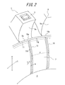
- a plurality of fin-like projections 10 are provided in the tire circumferential direction C with intervals therebetween in an outer surface of the sidewall portion 2 such that the projections 10 each protrude from the outer surface and extend, e.g. linearly in the tire radial direction R, as shown in the partially enlarged perspective view of FIG. 2 , in order to facilitate effective heat dissipation in the sidewall portion 2.
- the fin-like projections 10 generate air turbulences in the vicinity of the outer surface of the sidewall 2 and thus function as means for cooling the sidewall portion 2 with air when the tire runs and is rotated. Specifically, air in the vicinity of the outer surface of the sidewall portion 2 flows over the respective fin-like projections 10 each protruding from the outer surface and extending in the tire radial direction, swirls cold air above the outer surface of the sidewall 2, and flows with the cold air thus swirled therein into outer surface 2 portions between the respective two fin-like projections 10 adjacent to each other in the tire circumferential direction, thereby cooling the outer surface portions and thus facilitating heat dissipation from the outer surface of the sidewall portion 2.
- h represents the maximum protruding height, along a line normal to the outer surface of the sidewall 2, of the fin-like projection 10;
- p represents a pitch at which the fin-like projections 10 are provided in the tire circumferential direction;
- w represents the maximum width in the tire circumferential direction of the fin-like projection 10
- 1 ⁇ p/h ⁇ 20 and 1 ⁇ (p - w)/w ⁇ 50 in terms of more effectively cooling the sidewall portion 2 with air by the fin-like projections 10 to further effectively suppress a rise in internal temperature of the sidewall portion 2.
- the pitch p is to be measured at the center position in the tire radial direction of each fin-like configuration 10.
- the fin-like projections 10 may each have the maximum protruding height h in the range of 1 mm to 3 mm and the width w in the range of 1 mm to 2 mm and the number thereof provided in the tire circumferential direction may be in the range of 40 to 80.
- the protruding height h of each fin-like projection 10 is 2 mm over the entire length thereof
- the number of the fin-like projections 10 is 52
- the width w of each fin-like projection is 1.5 mm over the entire length thereof
- the fin-like projection 10 extends linearly in the tire radial direction, as shown in FIG. 1 and FIG. 2 , in terms of causing the air-cooling effect thereof in a satisfactory manner.
- the fin-like projection 10 may extend to be inclined at an angle of ⁇ 30° with respect to the tire radial direction and/or bend or curve in at least a portion thereof, although not shown in the drawings.
- the fin-like projection 10 extends from the inner end portion in the tire radial direction of the shoulder block 9 to a rim line position, i.e. over the entire length in the tire radial direction of the sidewall portion 2, in the example shown in FIGS. 1 and 2 .
- a length equivalent to at least 30 % of the length along the tire radial direction of the sidewall portion 2 in a state where the tire has been assembled with a prescribed rim and inflated at the normal internal pressure suffices as a length L along the tire radial direction of the fin-like projection 10 in terms of dissipating heat of the sidewall portion 2 in a satisfactorily effective manner.
- a surface, facing the outer side in the tire radial direction, of at least the end portion 10a on the outer side in the tire radial direction is formed to have an arcuate configuration protruding toward the tire inner surface side in a cross section in the tire width direction, as shown in FIG.
- the outer end portion 10a in the tire radial direction thus having an arcuate suface configuration in a cross section in the tire width direction, of each fin-like projection 10, absorbs strains generated in the vicinity of the outer end portion 10a in the tire radial direction of the fin-like projection 10, so that further growth of cracks generated in the vanity of the outer end portion 10a can be prevented by the arcuate surface of the outer end portion 10a.
- the outer end portions in the tire width direction of the shoulder blocks 9 and the outer end portions 10a in the tire radial direction of the fin-like projections 10 densely reside in a borderline region between the tread portion 3 and the sidewall portion 2, thereby facilitating occurrence of cracks in the borderline region.
- the number of potential crack-starting sites due to the aforementioned high density of the end portions i.e. a possibility of crack generation, can be effectively reduced by smoothly connecting the arcuate surface of the end portion 10a on the outer side in the tire radial direction of each fin-like projection 10 to the outer side surface 9a of the corresponding shoulder block 9 in the present embodiment.
- An annularly protruding side portion 11 is provided in a region, adjacent to the shoulder block 9, of the outer surface of the sidewall 2 such that the annularly protruding side portion 11 protrudes from the outer surface and has a protruding height H equal to the aforementioned protruding height h of the fin-like projection 10 in the present embodiment shown in the drawings.
- the respective fin-like projections 10 are integrally connected to the annularly protruding side portion 11 such that the arcuate surface of the end portion 10a on the outer side in the tire radial direction of each fin-like projection 10 constitutes a part of a surface, facing the outer side in the tire radial direction, of the annularly protruding side portion 11.
- the protruding height h of the fin-like projection 10 may differ from the protruding height H of the annularly protruding side portion 11 at a site where the fin-like projection 10 is connected to the annularly protruding side portion 11 (not shown in the drawings).
- Turned-up ends 5e of the carcass plies 5a, 5b turned up around each bead core 4 from the inner side toward the outer side in the tire width direction are preferably positioned on the outer side in the tire radial direction of a corresponding borderline Bp between the arcuate surface of the end portion 10a on the outer side in the tire radial direction of the fin-like projection 10 and a protruding surface 10b (protruding in parallel to the outer surface of the sidewall portion 2 in the example shown in the drawings) of the fin-like projection 10, as shown in FIG. 1 .
- the carcass plies 5a, 5b are turned up to a relatively high position on the outer side in the tire radial direction, whereby it is possible to increase rigidity of the sidewall portions 2 and thus reduce strains affecting the outer surfaces of the sidewall portions 2 and ii) the turned-up ends 5e, subjected to relatively large strains, of the carcass plies 5a, 5b are shifted in the tire radial direction from the corresponding borderline Bp between the arcuate surface of the outer end portion 10a in the tire radial direction and the protruding surface 10b of each fin-like projection 10, whereby it is possible to further effectively prevent crack generation in the outer surfaces of the sidewall portions 2.
- the turned-up ends 5e of the carcass plies 5a, 5b are each positioned on the outer side in the tire radial direction of the corresponding borderline Bp.
- a vulcanization-molding process for manufacturing our motorcycle pneumatic tire may use a vulcanization mold (not shown in the drawings) constituted, for example, of: a tread mold for forming the tread portion 3, which has an inner surface configuration corresponding to the outer surface configuration of the tread portion 3 and includes a plurality of segments which can be divided in the circumferential direction; and upper and lower side molds for forming the sidewall portions 2 and the bead portions 1, which have inner surface configurations corresponding to the outer surface configurations of the sidewall portions 2 and the bead portions 1, respectively.
- a vulcanization mold (not shown in the drawings) constituted, for example, of: a tread mold for forming the tread portion 3, which has an inner surface configuration corresponding to the outer surface configuration of the tread portion 3 and includes a plurality of segments which can be divided in the circumferential direction; and upper and lower side molds for forming the sidewall portions 2 and the bead portions 1, which have inner surface configurations corresponding to the outer surface configurations of the sidewall portions 2
- the borderline position Bm (or the tire outer surface position corresponding to the borderline position Bm) is positioned on the inner side in the tire radial direction than the borderline Bp between the arcuate surface of the outer end portion 10a in the tire radial direction of the fin-like projection 10 and the protruding surface 10b of the fin-like projection 10.
- the borderline position Bm of the molds is positioned at the protruding surface 10b of the fin-like projection 10 as in the present embodiment shown in the cross sectional view of FIG. 1 in terms of effectively preventing stress from concentrating at the arcuate surfaces of the fin-like projections 10.
- a side reinforcing layer (not shown in the drawings) having cords made of organic fiber, steel, or the like is preferably provided on the inner side in the tire width direction of the fin-like projections 10 inside the sidewall portion 2 such that the cords extend to be inclined with respect to the tire radial direction. Provision of the side reinforcing layer enhances rigidity of the sidewall portion 2 and reduces strains affecting the outer surface thereof, thereby effectively preventing crack generation in the outer surface as described above.
- the side reinforcing layer is preferably provided on the outer side in the tire width direction of the carcass plies 5a, 5b.
- test tires of our motorcycle pneumatic tires for travelling over rough terrain were prepared and performances thereof were evaluated as described below.
- the test tires each having a bias structure were prepared for two sizes: 120/80-19 and 110/90-19. More specifically, each test tire had a bias structure including two carcass plies and a layer of breaker made of nylon cords provided on the outer peripheral side of the carcass plies.
- Example 1 tire (for each size) had the structure as shown in FIGS. 1 and 2 .
- Comparative Example 1 tire (for each size) had the same structure as Example 1 tire, except that, although the former somehow had fin-like projections thereon, the outer ends in the tire radial direction of the fin-like projections thereof were not smoothly connected to outer side surfaces of shoulder blocks (i.e. the fin-like projections each terminated by a plane orthogonal to the extending direction thereof).
- Comparative Example 2 tire (for each size) had the same structure as Example 1 tire, except that the former lacked any fin-like projections provided on the outer surfaces of the sidewalls.
- Each of the test tires was made to run on a course specified for motocross competitions by a professional motocross rider.
- Example 2 tire Presence/absence of fin-like projection Present Present Absent Connection state of fin-like projection with outer side surface of shoulder block Smooth Not smooth - Protruding height h (mm) of fin-like projection 2 2 - Number of fin-like projections 52 52 - Width w (mm) of fin-like projection 1.5 1.5 - Evaluation results Controllability and stability performance 8 8 7 Generation of cracks Not observed Observed -
- Example 1 tire in which a surface of the end portion on the outer side in the tire radial direction of each fin-like projection is formed to have an arcuate configuration protruding toward the tire inner surface side in a cross section in the tire width direction; and the arcuate surface of the end portion on the outer side in the tire radial direction is smoothly connected to an outer side surface of shoulder block, with Comparative Example 1 tire where a surface of the end portion on the outer side in the tire radial direction of each fin-like projection is neither formed to have an arcuate configuration nor smoothly connected to an outer side surface of shoulder block, Example 1 tire exhibited no cracks generated in the outer surfaces of the sidewalls but Comparative Example 1 tire exhibited cracks in the outer surfaces of the sidewalls. It is therefore obvious that, our motorcycle pneumatic tire for travelling over
Landscapes
- Engineering & Computer Science (AREA)
- Mechanical Engineering (AREA)
- Tires In General (AREA)
Abstract
Description
- The present invention relates to a motorcycle pneumatic tire for travelling over rough terrain.
- A pneumatic tire for a motorcycle, mainly used in rough terrain including a swampy ground for competitions such as motocross, enduro races and the like, is subjected to relatively large deformation, as compared with tires for a paved road in general, because the former serves for traveling on a rough terrain surface having ruts and irregular projections/dents made by other vehicles.
Further, the tire of this kind is generally used in a state where the tire has been inflated at relatively low internal pressure, as compared with other tires in general, so that the tire can demonstrate good traction and gripping performances with respect to the rough terrain surface. Consequently, deformation of sidewall portions susceptible to low internal pressure of the tire is intensified and internal temperature in the sidewall portions increases, such that the rise in temperature reduces rigidity in the sidewall portion and thus further facilitates deformation of the sidewall portion, which then further raises the internal temperature in the sidewall portions, i.e. creates a vicious circle of more deformation caused by higher temperature. Controllability and stability of the tire tends to deteriorate over time during use thereof, accordingly. - In this connection,
PTL 1, although it does not relate to a pneumatic tire for a motorcycle as described above, discloses a run-flat tire having a crescent-shaped side-reinforcing rubber in a side portion thereof, wherein the tire comprises "recessed and protruded parts for generating air turbulences, constituted of grooves and projections and formed to extend in at least a part of a tire side portion", for decreasing temperature in the tire side portion. - PTL 1:
WO2007/032405 - However, when an outer surface of a sidewall portion of the aforementioned motorcycle tire, which tire is likely to be used in rough terrain, is provided with the "recessed and protruded" configurations according to the technique described in
PTL 1, the recessed and protruded configurations locally provided in the outer surface of the sidewall portion susceptible to deformation in running on rough terrain, of the tire, tend to serve as starting points of cracks which may grow in the outer surface of the sidewall portion. That is, the recessed and protruded configurations according toPTL 1, directly introduced to the aforementioned motorcycle tire for off-road travelling, causes a problem in that the configurations may deteriorate durability of a sidewall of the tire, although they somehow facilitate heat dissipation the sidewall portion. - In view of the problem described above, a motorcycle pneumatic tire of the present disclosure is a tire for travelling over rough terrain, having a pair of bead portions, sidewall portions respectively continuous with the bead portions and extending in the tire radial direction, and a tread portion continuous with the respective sidewall portions, wherein: the tire has a plurality of fin-like projections provided in the tire circumferential direction with intervals therebetween in an outer surface of the sidewall portion such that the fin-like projections each protrude from the outer surface and extend in the tire radial direction; each fin-like projection has an end portion on the inner side in the tire radial direction and an end portion in the outer side in the tire radial direction, and a surface of at least the end portion on the outer side in the tire radial direction is formed to have an arcuate configuration protruding toward the tire inner surface side in a cross section in the width direction of the tire; and the arcuate surface of the end portion on the outer side in the tire radial direction of the fin-like projection is smoothly connected to an outer side surface of a shoulder block provided on the outermost side in the tire width direction of the tread portion.
- The tire can well suppress a rise in internal temperature of a sidewall portion of a tire and thus a decrease in rigidity of the sidewall portion, while maintaining good durability of the sidewall portion, thereby successfully exhibiting good controllability and stability performance over a long period.
- In the accompanying drawings, wherein:
-
FIG. 1 is a cross sectional view in the tire width direction, showing a half portion of a motorcycle pneumatic tire according to an embodiment of our motorcycle pneumatic tire; -
FIG. 2 is a partially enlarged perspective view showing an outer surface of a sidewall portion of the tire ofFIG. 1 . - An embodiment of our motorcycle pneumatic tire will be demonstratively described hereinafter with reference to the drawings.
A pneumatic tire for a motorcycle, shown inFIG. 1 , mainly serves for running on rough terrain including a swampy ground and has a pair ofbead portions 1,sidewall portions 2 respectively continuous with thebead portions 1 and extending in the tire radial direction, and atread portion 3 continuous with therespective sidewall portions 2. - The tire shown in
FIG. 1 further has:bead cores 4 respectively provided in the pair ofbead portions 1; at least one (two in the drawing)carcass ply tread portion 3 via therespective sidewall portions 2 to thebead portions 1 and being turned up around therespective bead cores 4; and abelt 6 constituted of, for example, a single belt layer and provided on the outer peripheral side of a crown region, i.e. on the outer side in the tire radial direction, of thecarcass ply - The
carcass ply - The single belt layer (or each of the belt layers) of the
belt 6 is formed of at least one organic fiber cord or steel cord extending at a predetermined angle with respect to the tire circumferential direction. In a case where the belt is constituted of a plurality of belt layers adjacent to each other in the radial direction, the cords of one belt layer and the cords of another belt layer adjacent to the one belt layer may extend in opposite directions alternately with respect to the tire circumferential direction. - A plurality of
blocks tread portion 3 which is brought into contact with the road surface on the outer peripheral side of thebelt 6. - The
sidewall portions 2 of the motorcycle pneumatic tire for travelling over rough terrain as described above may be subjected to significant bending deformation, depending on a state of a road surface on which the tire travels and how the tire is used. A rise in internal temperature resulted from the bending deformation of thesidewall portion 2 may decrease rigidity of the sidewall portion over time and deteriorate controllability and stability of the tire as the use of the tire continues. In view of this, in our motorcycle pneumatic tire, a plurality of fin-like projections 10 are provided in the tire circumferential direction C with intervals therebetween in an outer surface of thesidewall portion 2 such that theprojections 10 each protrude from the outer surface and extend, e.g. linearly in the tire radial direction R, as shown in the partially enlarged perspective view ofFIG. 2 , in order to facilitate effective heat dissipation in thesidewall portion 2. - The fin-
like projections 10 generate air turbulences in the vicinity of the outer surface of thesidewall 2 and thus function as means for cooling thesidewall portion 2 with air when the tire runs and is rotated.
Specifically, air in the vicinity of the outer surface of thesidewall portion 2 flows over the respective fin-like projections 10 each protruding from the outer surface and extending in the tire radial direction, swirls cold air above the outer surface of thesidewall 2, and flows with the cold air thus swirled therein intoouter surface 2 portions between the respective two fin-like projections 10 adjacent to each other in the tire circumferential direction, thereby cooling the outer surface portions and thus facilitating heat dissipation from the outer surface of thesidewall portion 2. - In this connection, provided that: h represents the maximum protruding height, along a line normal to the outer surface of the
sidewall 2, of the fin-like projection 10; p represents a pitch at which the fin-like projections 10 are provided in the tire circumferential direction; and w represents the maximum width in the tire circumferential direction of the fin-like projection 10, it is preferable that 1 ≤ p/h ≤ 20 and 1 ≤ (p - w)/w ≤ 50 in terms of more effectively cooling thesidewall portion 2 with air by the fin-like projections 10 to further effectively suppress a rise in internal temperature of thesidewall portion 2. The pitch p is to be measured at the center position in the tire radial direction of each fin-like configuration 10. - More specifically, the fin-
like projections 10 may each have the maximum protruding height h in the range of 1 mm to 3 mm and the width w in the range of 1 mm to 2 mm and the number thereof provided in the tire circumferential direction may be in the range of 40 to 80. In the tire exemplarily shown inFIG. 1 , in particular, the protruding height h of each fin-like projection 10 is 2 mm over the entire length thereof, the number of the fin-like projections 10 is 52, and the width w of each fin-like projection is 1.5 mm over the entire length thereof - It is preferable that the fin-
like projection 10 extends linearly in the tire radial direction, as shown inFIG. 1 andFIG. 2 , in terms of causing the air-cooling effect thereof in a satisfactory manner. However, the fin-like projection 10 may extend to be inclined at an angle of ≤ 30° with respect to the tire radial direction and/or bend or curve in at least a portion thereof, although not shown in the drawings. - The fin-
like projection 10 extends from the inner end portion in the tire radial direction of theshoulder block 9 to a rim line position, i.e. over the entire length in the tire radial direction of thesidewall portion 2, in the example shown inFIGS. 1 and2 . However, a length equivalent to at least 30 % of the length along the tire radial direction of thesidewall portion 2 in a state where the tire has been assembled with a prescribed rim and inflated at the normal internal pressure suffices as a length L along the tire radial direction of the fin-like projection 10 in terms of dissipating heat of thesidewall portion 2 in a satisfactorily effective manner. - There is a possibility that cracks are generated in the outer surface of the
sidewall portion 2 as the use of the tire continues, and provision of the fin-like projections 10 as described above in the outer surface of thesidewall portion 2 may facilitate growth of cracks along the fin-like configurations 10 at theouter end portion 10a in the tire radial direction thereof in particular, thereby deteriorating durability of thesidewall portion 2.
In view of this, of an end portion on the inner side in the tire radial direction and an end portion on the outer side in the tire radial direction of each fin-like projection 10, a surface, facing the outer side in the tire radial direction, of at least theend portion 10a on the outer side in the tire radial direction is formed to have an arcuate configuration protruding toward the tire inner surface side in a cross section in the tire width direction, as shown inFIG. 1 ; and the arcuate surface of theend portion 10a on the outer side in the tire radial direction is smoothly connected to anouter side surface 9a, facing the outer side in the tire width direction, of theshoulder block 9 provided on the outermost side in the tire width direction of the tread portion 3 (among the plurality ofblocks 7 to 9 provided in the tread portion 3) in our motorcycle pneumatic tire. - Accordingly, the
outer end portion 10a in the tire radial direction thus having an arcuate suface configuration in a cross section in the tire width direction, of each fin-like projection 10, absorbs strains generated in the vicinity of theouter end portion 10a in the tire radial direction of the fin-like projection 10, so that further growth of cracks generated in the vanity of theouter end portion 10a can be prevented by the arcuate surface of theouter end portion 10a.
The outer end portions in the tire width direction of theshoulder blocks 9 and theouter end portions 10a in the tire radial direction of the fin-like projections 10 densely reside in a borderline region between thetread portion 3 and thesidewall portion 2, thereby facilitating occurrence of cracks in the borderline region. However, the number of potential crack-starting sites due to the aforementioned high density of the end portions, i.e. a possibility of crack generation, can be effectively reduced by smoothly connecting the arcuate surface of theend portion 10a on the outer side in the tire radial direction of each fin-like projection 10 to theouter side surface 9a of thecorresponding shoulder block 9 in the present embodiment. - An annularly
protruding side portion 11 is provided in a region, adjacent to theshoulder block 9, of the outer surface of thesidewall 2 such that the annularly protrudingside portion 11 protrudes from the outer surface and has a protruding height H equal to the aforementioned protruding height h of the fin-like projection 10 in the present embodiment shown in the drawings. The respective fin-like projections 10 are integrally connected to the annularly protrudingside portion 11 such that the arcuate surface of theend portion 10a on the outer side in the tire radial direction of each fin-like projection 10 constitutes a part of a surface, facing the outer side in the tire radial direction, of the annularly protrudingside portion 11. - Linking the
end portions 10a on the outer side in the tire radial direction of the fin-like projections 10 by the annularly protrudingside portion 11 as described above is preferable because stress concentrated on some of theouter ends 10a in the tire radial direction of the fin-like projections 10 can be dispersed in the tire circumferential direction by the annularly protrudingside portion 11 linking theouter ends 10a in the tire radial direction of the fin-like projections 10, whereby crack generation there can be further effectively prevented.
In this connection, the protruding height h of the fin-like projection 10 may differ from the protruding height H of the annularly protrudingside portion 11 at a site where the fin-like projection 10 is connected to the annularly protruding side portion 11 (not shown in the drawings). - Turned-up
ends 5e of thecarcass plies bead core 4 from the inner side toward the outer side in the tire width direction are preferably positioned on the outer side in the tire radial direction of a corresponding borderline Bp between the arcuate surface of theend portion 10a on the outer side in the tire radial direction of the fin-like projection 10 and aprotruding surface 10b (protruding in parallel to the outer surface of thesidewall portion 2 in the example shown in the drawings) of the fin-like projection 10, as shown inFIG. 1 . According to this structure, i) thecarcass plies sidewall portions 2 and thus reduce strains affecting the outer surfaces of thesidewall portions 2 and ii) the turned-up ends 5e, subjected to relatively large strains, of thecarcass plies outer end portion 10a in the tire radial direction and theprotruding surface 10b of each fin-like projection 10, whereby it is possible to further effectively prevent crack generation in the outer surfaces of thesidewall portions 2. In a case where two or more carcass plies 5a, 5b are provided as in the tire shown in the drawings, it is particularly preferable that the turned-up ends 5e of thecarcass plies - A vulcanization-molding process for manufacturing our motorcycle pneumatic tire may use a vulcanization mold (not shown in the drawings) constituted, for example, of: a tread mold for forming the
tread portion 3, which has an inner surface configuration corresponding to the outer surface configuration of thetread portion 3 and includes a plurality of segments which can be divided in the circumferential direction; and upper and lower side molds for forming thesidewall portions 2 and thebead portions 1, which have inner surface configurations corresponding to the outer surface configurations of thesidewall portions 2 and thebead portions 1, respectively. - In a case where a tire is vulcanization-molded by using the vulcanization mold as described above, stress tends to concentrate in the tire thus manufactured, when the tire is used, at a tire outer surface position thereof corresponding to a borderline position Bm (indicated by a phantom line in
FIG. 1 ) between the tread mold and the side molds of the vulcanization mold in a clamped state. In view of this, it is preferable in a cross sectional view in the width direction of the tire that the borderline position Bm (or the tire outer surface position corresponding to the borderline position Bm) is positioned on the inner side in the tire radial direction than the borderline Bp between the arcuate surface of theouter end portion 10a in the tire radial direction of the fin-like projection 10 and theprotruding surface 10b of the fin-like projection 10. According to this arrangement, it is possible to effectively prevent stress from concentrating at the arcuate surfaces of the fin-like projections 10 (stress would concentrate at the arcuate surfaces of the fin-like projections 10 if the borderline position Bm between the tread mold and the side molds were to be positioned at the arcuate surfaces of the fin-like projections 10). It is particularly preferable that the borderline position Bm of the molds is positioned at theprotruding surface 10b of the fin-like projection 10 as in the present embodiment shown in the cross sectional view ofFIG. 1 in terms of effectively preventing stress from concentrating at the arcuate surfaces of the fin-like projections 10. - A side reinforcing layer (not shown in the drawings) having cords made of organic fiber, steel, or the like is preferably provided on the inner side in the tire width direction of the fin-
like projections 10 inside thesidewall portion 2 such that the cords extend to be inclined with respect to the tire radial direction. Provision of the side reinforcing layer enhances rigidity of thesidewall portion 2 and reduces strains affecting the outer surface thereof, thereby effectively preventing crack generation in the outer surface as described above. The side reinforcing layer is preferably provided on the outer side in the tire width direction of thecarcass plies - Test tires of our motorcycle pneumatic tires for travelling over rough terrain were prepared and performances thereof were evaluated as described below.
The test tires each having a bias structure were prepared for two sizes: 120/80-19 and 110/90-19. More specifically, each test tire had a bias structure including two carcass plies and a layer of breaker made of nylon cords provided on the outer peripheral side of the carcass plies. - Example 1 tire (for each size) had the structure as shown in
FIGS. 1 and2 . Comparative Example 1 tire (for each size) had the same structure as Example 1 tire, except that, although the former somehow had fin-like projections thereon, the outer ends in the tire radial direction of the fin-like projections thereof were not smoothly connected to outer side surfaces of shoulder blocks (i.e. the fin-like projections each terminated by a plane orthogonal to the extending direction thereof). Comparative Example 2 tire (for each size) had the same structure as Example 1 tire, except that the former lacked any fin-like projections provided on the outer surfaces of the sidewalls. Each of the test tires was made to run on a course specified for motocross competitions by a professional motocross rider. Controllability and stability performance, as well as how the controllability and stability performance was maintained after running for a predetermined time, was determined for the test tire by sensory evaluation by the motocross rider and the evaluation results were expressed by points (10 was the full marks). Further, presence/absence of crack generation in the outer surfaces of the sidewall portions after the running was examined for the test tire. These evaluation results, as well as the relevant characteristics, of the respective test tires are shown in Table 1 in a summarized manner.Table 1 Example 1 tire Comp. Example 1 tire Comp. Example 2 tire Presence/absence of fin-like projection Present Present Absent Connection state of fin-like projection with outer side surface of shoulder block Smooth Not smooth - Protruding height h (mm) of fin- like projection 2 2 - Number of fin-like projections 52 52 - Width w (mm) of fin-like projection 1.5 1.5 - Evaluation results Controllability and stability performance 8 8 7 Generation of cracks Not observed Observed - - It is understood from the results shown in Table 1 that, because of provision of the fin (rib)-like projections, controllability and stability performance does not deteriorate in Example 1 tire and Comparative Example 1 tire as in Comparative Example 2. Further, comparing Example 1 tire, in which a surface of the end portion on the outer side in the tire radial direction of each fin-like projection is formed to have an arcuate configuration protruding toward the tire inner surface side in a cross section in the tire width direction; and the arcuate surface of the end portion on the outer side in the tire radial direction is smoothly connected to an outer side surface of shoulder block, with Comparative Example 1 tire where a surface of the end portion on the outer side in the tire radial direction of each fin-like projection is neither formed to have an arcuate configuration nor smoothly connected to an outer side surface of shoulder block, Example 1 tire exhibited no cracks generated in the outer surfaces of the sidewalls but Comparative Example 1 tire exhibited cracks in the outer surfaces of the sidewalls. It is therefore obvious that, our motorcycle pneumatic tire for travelling over rough terrain can exhibit good controllability and stability performance over a long period, while maintaining good durability of the sidewall portion.
-
- 1
- Bead portion
- 2
- Sidewall portion
- 3
- Tread portion
- 4
- Bead core
- 5a, 5b
- Carcass ply
- 5e
- Turned-up end of carcass ply
- 6
- Belt
- 7, 8
- Block
- 9
- Shoulder block
- 9a
- Outer side surface of shoulder block
- 10
- Fin-like projection
- 10a
- End portion on the outer side in the tire radial direction of fin-like projection
- 10b
- Protruding surface of fin-like projection
- 11
- Annularly protruding side portion
- Bp
- Borderline between arcuate surface of the outer end portion in the tire radial direction and protruding surface of fin-like projection
- Bm
- Borderline position between tread mold and side molds
- L
- Length along the tire radial direction of fin-like projection
- La
- Length along the tire radial direction of radially outer end of fin-like projection
- P
- Pitch at which fin-like projections are provided in the tire circumferential direction
- h
- Protruding height of fin-like projection
- w
- Width in the tire circumferential direction of fin-like projection
- H
- Protruding height of annularly protruding side portion
Claims (5)
- A motorcycle pneumatic tire for travelling over rough terrain, having a pair of bead portions, sidewall portions respectively continuous with the bead portions and extending in the tire radial direction, and a tread portion continuous with the respective sidewall portions, wherein:the tire has a plurality of fin-like projections provided in the tire circumferential direction with intervals therebetween in an outer surface of the sidewall portion such that the fin-like projections each protrude from the outer surface and extend in the tire radial direction;each fin-like projection has an end portion on the inner side in the tire radial direction and an end portion in the outer side in the tire radial direction, and a surface of at least the end portion on the outer side in the tire radial direction is formed to have an arcuate configuration protruding toward the tire inner surface side in a cross section in the width direction of the tire; andthe arcuate surface of the end portion on the outer side in the tire radial direction of the fin-like projection is smoothly connected to an outer side surface of a shoulder block provided on the outermost side in the tire width direction of the tread portion.
- The motorcycle pneumatic tire of claim 1, wherein:the tire further has bead cores respectively embedded in the pair of bead portions and at least one carcass ply extending from the tread portion via the respective sidewall portions to the bead portions and being turned up around the respective bead cores; anda turned-up end of the carcass ply is positioned, in the cross section of the tire in the width direction thereof, on the outer side in the tire radial direction of a borderline between the arcuate surface of the end portion on the outer side in the tire radial direction of the fin-like projection and a protruding surface of the fin-like projection.
- The motorcycle pneumatic tire of claim 1 or 2, wherein an annularly protruding side portion is provided in a region, adjacent to the shoulder block, of the outer surface of the sidewall such that the annularly protruding side portion protrudes from the outer surface, and the respective end portions on the outer side in the tire radial direction of the fin-like projections are linked by the annularly protruding side portion.
- The motorcycle pneumatic tire of any of claims 1 to 3, wherein, provided that a vulcanization mold for molding the tire is constituted of a tread mold for forming the tread portion and side molds for forming the sidewall portions and that Bm represents a borderline position between the tread mold and the side molds of the vulcanization mold in a clamped state thereof, the borderline position Bm or a tire outer surface position corresponding to the borderline position Bm is located on the inner side in the tire radial direction than the borderline between the arcuate surface of the outer end portion in the tire radial direction of the fin-like projection and the protruding surface of the fin-like projection in the cross section of the tire in the width direction thereof
- The motorcycle pneumatic tire of any of claims 1 to 4, wherein a side reinforcing layer having cords is provided on the inner side in the tire width direction of the fin-like projections inside the sidewall portion such that the cords extend to be inclined with respect to the tire radial direction.
Applications Claiming Priority (2)
| Application Number | Priority Date | Filing Date | Title |
|---|---|---|---|
| JP2013023700A JP5544028B1 (en) | 2013-02-08 | 2013-02-08 | Pneumatic tires for motorcycles |
| PCT/JP2014/000196 WO2014122885A1 (en) | 2013-02-08 | 2014-01-16 | Pneumatic tire for automatic two-wheeled vehicle |
Publications (3)
| Publication Number | Publication Date |
|---|---|
| EP2955038A1 true EP2955038A1 (en) | 2015-12-16 |
| EP2955038A4 EP2955038A4 (en) | 2016-10-19 |
| EP2955038B1 EP2955038B1 (en) | 2019-07-10 |
Family
ID=51299486
Family Applications (1)
| Application Number | Title | Priority Date | Filing Date |
|---|---|---|---|
| EP14749564.2A Active EP2955038B1 (en) | 2013-02-08 | 2014-01-16 | Pneumatic tire for off-road motorcycle |
Country Status (5)
| Country | Link |
|---|---|
| US (1) | US10259269B2 (en) |
| EP (1) | EP2955038B1 (en) |
| JP (1) | JP5544028B1 (en) |
| CN (1) | CN104995042B (en) |
| WO (1) | WO2014122885A1 (en) |
Cited By (1)
| Publication number | Priority date | Publication date | Assignee | Title |
|---|---|---|---|---|
| WO2018065693A1 (en) * | 2016-10-06 | 2018-04-12 | Compagnie Generale Des Etablissements Michelin | Carcass and crown reinforcements for motorbike tyre |
Families Citing this family (8)
| Publication number | Priority date | Publication date | Assignee | Title |
|---|---|---|---|---|
| FR3045480B1 (en) * | 2015-12-16 | 2017-12-22 | Michelin & Cie | PNEUMATIC HAVING IMPROVED WEAR AND ROLL RESISTANCE PROPERTIES |
| JP6584334B2 (en) * | 2016-01-28 | 2019-10-02 | 株式会社ブリヂストン | tire |
| JP6728801B2 (en) * | 2016-03-14 | 2020-07-22 | 住友ゴム工業株式会社 | Pneumatic tire |
| CN106394128A (en) * | 2016-11-02 | 2017-02-15 | 青岛双星轮胎工业有限公司 | All-steel mud-field tire |
| JP6962126B2 (en) * | 2017-10-18 | 2021-11-05 | 住友ゴム工業株式会社 | tire |
| JP7006238B2 (en) * | 2017-12-19 | 2022-01-24 | 住友ゴム工業株式会社 | Tires and tire sets |
| JP7040046B2 (en) * | 2018-01-25 | 2022-03-23 | 住友ゴム工業株式会社 | Motorcycle tires |
| JP6879409B1 (en) * | 2020-05-25 | 2021-06-02 | 住友ゴム工業株式会社 | Motorcycle tires for running on rough terrain |
Family Cites Families (17)
| Publication number | Priority date | Publication date | Assignee | Title |
|---|---|---|---|---|
| JPS6033105A (en) * | 1983-08-01 | 1985-02-20 | Sumitomo Rubber Ind Ltd | Tire for motorcycle |
| JP2571498B2 (en) | 1992-08-18 | 1997-01-16 | 三ツ星ベルト株式会社 | Bicycle tires |
| JPH10907A (en) | 1996-06-18 | 1998-01-06 | Matsushita Electric Ind Co Ltd | Tires, wheels, vehicles and manufacturing methods |
| JP4577053B2 (en) * | 2005-03-15 | 2010-11-10 | 横浜ゴム株式会社 | Pneumatic tire |
| US8522844B2 (en) | 2005-09-13 | 2013-09-03 | Bridgestone Corporation | Pneumatic tire with heat dissipating side portion |
| JP5088774B2 (en) * | 2007-03-30 | 2012-12-05 | 株式会社ブリヂストン | Pneumatic tires for motorcycles |
| JP2009029384A (en) * | 2007-07-30 | 2009-02-12 | Bridgestone Corp | Pneumatic tire |
| JP4235241B1 (en) * | 2007-11-26 | 2009-03-11 | 住友ゴム工業株式会社 | Pneumatic tire for motocross |
| WO2009084634A1 (en) | 2007-12-28 | 2009-07-09 | Bridgestone Corporation | Pneumatic tire |
| US8689847B2 (en) * | 2008-05-20 | 2014-04-08 | Bridgestone Corporation | Pneumatic tire |
| JP5346600B2 (en) * | 2009-01-19 | 2013-11-20 | 株式会社ブリヂストン | Tires for motorcycles |
| JP2010167832A (en) * | 2009-01-20 | 2010-08-05 | Bridgestone Corp | Pneumatic tire |
| JP4886812B2 (en) * | 2009-05-18 | 2012-02-29 | 東洋ゴム工業株式会社 | Pneumatic tire |
| JP4989755B2 (en) * | 2010-07-09 | 2012-08-01 | 住友ゴム工業株式会社 | Pneumatic tire |
| JP5632233B2 (en) * | 2010-08-23 | 2014-11-26 | 株式会社ブリヂストン | Pneumatic tires for motorcycles |
| JP2012206669A (en) * | 2011-03-30 | 2012-10-25 | Bridgestone Corp | Motorcycle tire |
| JP5450515B2 (en) * | 2011-06-10 | 2014-03-26 | 住友ゴム工業株式会社 | Motorcycle tire for rough terrain |
-
2013
- 2013-02-08 JP JP2013023700A patent/JP5544028B1/en not_active Expired - Fee Related
-
2014
- 2014-01-16 US US14/761,478 patent/US10259269B2/en not_active Expired - Fee Related
- 2014-01-16 WO PCT/JP2014/000196 patent/WO2014122885A1/en not_active Ceased
- 2014-01-16 EP EP14749564.2A patent/EP2955038B1/en active Active
- 2014-01-16 CN CN201480007914.9A patent/CN104995042B/en active Active
Cited By (2)
| Publication number | Priority date | Publication date | Assignee | Title |
|---|---|---|---|---|
| WO2018065693A1 (en) * | 2016-10-06 | 2018-04-12 | Compagnie Generale Des Etablissements Michelin | Carcass and crown reinforcements for motorbike tyre |
| FR3057207A1 (en) * | 2016-10-06 | 2018-04-13 | Compagnie Generale Des Etablissements Michelin | CARCASS AND PNEUMATIC TOP FOR MOTORCYCLE FRAME |
Also Published As
| Publication number | Publication date |
|---|---|
| CN104995042A (en) | 2015-10-21 |
| JP5544028B1 (en) | 2014-07-09 |
| EP2955038A4 (en) | 2016-10-19 |
| EP2955038B1 (en) | 2019-07-10 |
| WO2014122885A1 (en) | 2014-08-14 |
| JP2014151792A (en) | 2014-08-25 |
| US20150360520A1 (en) | 2015-12-17 |
| US10259269B2 (en) | 2019-04-16 |
| CN104995042B (en) | 2017-05-31 |
Similar Documents
| Publication | Publication Date | Title |
|---|---|---|
| EP2955038B1 (en) | Pneumatic tire for off-road motorcycle | |
| US11850890B2 (en) | Pneumatic tire | |
| US11654719B2 (en) | Pneumatic tire | |
| US10632792B2 (en) | Pneumatic tire | |
| JP6728801B2 (en) | Pneumatic tire | |
| JP6148740B2 (en) | Motorcycle tires and tire vulcanization molds for rough terrain travel | |
| JP4202168B2 (en) | Pneumatic radial tire | |
| JP2013180637A (en) | Pneumatic tire | |
| US20170174009A1 (en) | Pneumatic Tire | |
| WO2016167122A1 (en) | Run-flat tire | |
| JPWO2012176912A1 (en) | Pneumatic tires for motorcycles | |
| JP4533181B2 (en) | Pneumatic tires for motorcycles | |
| JP2019034727A (en) | Off-road tire | |
| CN107848342B (en) | Pneumatic tire for motorcycle | |
| JP6634710B2 (en) | Pneumatic tire | |
| US20210291593A1 (en) | Heavy duty pneumatic tire and manufacturing method thereof | |
| US11104185B2 (en) | Method of manufacturing motorcycle tire for uneven terrain travel | |
| JP4234468B2 (en) | Pneumatic tire | |
| CN104039567B (en) | tires for motorcycles | |
| US8905098B2 (en) | Pneumatic tire | |
| JP6623766B2 (en) | Manufacturing method of motorcycle tire for rough terrain | |
| US12459302B2 (en) | Pneumatic tire | |
| JP2014159178A (en) | Tire for rough terrain running vehicle | |
| WO2020110474A1 (en) | Pneumatic tire | |
| JP6107343B2 (en) | Manufacturing method of pneumatic bias tire |
Legal Events
| Date | Code | Title | Description |
|---|---|---|---|
| PUAI | Public reference made under article 153(3) epc to a published international application that has entered the european phase |
Free format text: ORIGINAL CODE: 0009012 |
|
| 17P | Request for examination filed |
Effective date: 20150728 |
|
| AK | Designated contracting states |
Kind code of ref document: A1 Designated state(s): AL AT BE BG CH CY CZ DE DK EE ES FI FR GB GR HR HU IE IS IT LI LT LU LV MC MK MT NL NO PL PT RO RS SE SI SK SM TR |
|
| AX | Request for extension of the european patent |
Extension state: BA ME |
|
| DAX | Request for extension of the european patent (deleted) | ||
| A4 | Supplementary search report drawn up and despatched |
Effective date: 20160919 |
|
| RIC1 | Information provided on ipc code assigned before grant |
Ipc: B60C 11/01 20060101AFI20160913BHEP Ipc: B60C 13/02 20060101ALI20160913BHEP Ipc: B60C 11/11 20060101ALI20160913BHEP |
|
| STAA | Information on the status of an ep patent application or granted ep patent |
Free format text: STATUS: EXAMINATION IS IN PROGRESS |
|
| 17Q | First examination report despatched |
Effective date: 20180214 |
|
| REG | Reference to a national code |
Ref country code: DE Ref legal event code: R079 Ref document number: 602014049839 Country of ref document: DE Free format text: PREVIOUS MAIN CLASS: B60C0013000000 Ipc: B60C0013020000 |
|
| RIC1 | Information provided on ipc code assigned before grant |
Ipc: B60C 11/11 20060101ALI20181219BHEP Ipc: B60C 15/00 20060101ALI20181219BHEP Ipc: B29D 30/06 20060101ALI20181219BHEP Ipc: B60C 13/02 20060101AFI20181219BHEP |
|
| GRAP | Despatch of communication of intention to grant a patent |
Free format text: ORIGINAL CODE: EPIDOSNIGR1 |
|
| STAA | Information on the status of an ep patent application or granted ep patent |
Free format text: STATUS: GRANT OF PATENT IS INTENDED |
|
| INTG | Intention to grant announced |
Effective date: 20190129 |
|
| GRAS | Grant fee paid |
Free format text: ORIGINAL CODE: EPIDOSNIGR3 |
|
| GRAA | (expected) grant |
Free format text: ORIGINAL CODE: 0009210 |
|
| STAA | Information on the status of an ep patent application or granted ep patent |
Free format text: STATUS: THE PATENT HAS BEEN GRANTED |
|
| AK | Designated contracting states |
Kind code of ref document: B1 Designated state(s): AL AT BE BG CH CY CZ DE DK EE ES FI FR GB GR HR HU IE IS IT LI LT LU LV MC MK MT NL NO PL PT RO RS SE SI SK SM TR |
|
| REG | Reference to a national code |
Ref country code: GB Ref legal event code: FG4D |
|
| REG | Reference to a national code |
Ref country code: CH Ref legal event code: EP Ref country code: AT Ref legal event code: REF Ref document number: 1153151 Country of ref document: AT Kind code of ref document: T Effective date: 20190715 |
|
| REG | Reference to a national code |
Ref country code: DE Ref legal event code: R096 Ref document number: 602014049839 Country of ref document: DE |
|
| REG | Reference to a national code |
Ref country code: IE Ref legal event code: FG4D |
|
| REG | Reference to a national code |
Ref country code: NL Ref legal event code: MP Effective date: 20190710 |
|
| REG | Reference to a national code |
Ref country code: LT Ref legal event code: MG4D |
|
| REG | Reference to a national code |
Ref country code: AT Ref legal event code: MK05 Ref document number: 1153151 Country of ref document: AT Kind code of ref document: T Effective date: 20190710 |
|
| PG25 | Lapsed in a contracting state [announced via postgrant information from national office to epo] |
Ref country code: FI Free format text: LAPSE BECAUSE OF FAILURE TO SUBMIT A TRANSLATION OF THE DESCRIPTION OR TO PAY THE FEE WITHIN THE PRESCRIBED TIME-LIMIT Effective date: 20190710 Ref country code: HR Free format text: LAPSE BECAUSE OF FAILURE TO SUBMIT A TRANSLATION OF THE DESCRIPTION OR TO PAY THE FEE WITHIN THE PRESCRIBED TIME-LIMIT Effective date: 20190710 Ref country code: BG Free format text: LAPSE BECAUSE OF FAILURE TO SUBMIT A TRANSLATION OF THE DESCRIPTION OR TO PAY THE FEE WITHIN THE PRESCRIBED TIME-LIMIT Effective date: 20191010 Ref country code: AT Free format text: LAPSE BECAUSE OF FAILURE TO SUBMIT A TRANSLATION OF THE DESCRIPTION OR TO PAY THE FEE WITHIN THE PRESCRIBED TIME-LIMIT Effective date: 20190710 Ref country code: SE Free format text: LAPSE BECAUSE OF FAILURE TO SUBMIT A TRANSLATION OF THE DESCRIPTION OR TO PAY THE FEE WITHIN THE PRESCRIBED TIME-LIMIT Effective date: 20190710 Ref country code: PT Free format text: LAPSE BECAUSE OF FAILURE TO SUBMIT A TRANSLATION OF THE DESCRIPTION OR TO PAY THE FEE WITHIN THE PRESCRIBED TIME-LIMIT Effective date: 20191111 Ref country code: NL Free format text: LAPSE BECAUSE OF FAILURE TO SUBMIT A TRANSLATION OF THE DESCRIPTION OR TO PAY THE FEE WITHIN THE PRESCRIBED TIME-LIMIT Effective date: 20190710 Ref country code: LT Free format text: LAPSE BECAUSE OF FAILURE TO SUBMIT A TRANSLATION OF THE DESCRIPTION OR TO PAY THE FEE WITHIN THE PRESCRIBED TIME-LIMIT Effective date: 20190710 Ref country code: NO Free format text: LAPSE BECAUSE OF FAILURE TO SUBMIT A TRANSLATION OF THE DESCRIPTION OR TO PAY THE FEE WITHIN THE PRESCRIBED TIME-LIMIT Effective date: 20191010 |
|
| PG25 | Lapsed in a contracting state [announced via postgrant information from national office to epo] |
Ref country code: ES Free format text: LAPSE BECAUSE OF FAILURE TO SUBMIT A TRANSLATION OF THE DESCRIPTION OR TO PAY THE FEE WITHIN THE PRESCRIBED TIME-LIMIT Effective date: 20190710 Ref country code: LV Free format text: LAPSE BECAUSE OF FAILURE TO SUBMIT A TRANSLATION OF THE DESCRIPTION OR TO PAY THE FEE WITHIN THE PRESCRIBED TIME-LIMIT Effective date: 20190710 Ref country code: GR Free format text: LAPSE BECAUSE OF FAILURE TO SUBMIT A TRANSLATION OF THE DESCRIPTION OR TO PAY THE FEE WITHIN THE PRESCRIBED TIME-LIMIT Effective date: 20191011 Ref country code: AL Free format text: LAPSE BECAUSE OF FAILURE TO SUBMIT A TRANSLATION OF THE DESCRIPTION OR TO PAY THE FEE WITHIN THE PRESCRIBED TIME-LIMIT Effective date: 20190710 Ref country code: RS Free format text: LAPSE BECAUSE OF FAILURE TO SUBMIT A TRANSLATION OF THE DESCRIPTION OR TO PAY THE FEE WITHIN THE PRESCRIBED TIME-LIMIT Effective date: 20190710 Ref country code: IS Free format text: LAPSE BECAUSE OF FAILURE TO SUBMIT A TRANSLATION OF THE DESCRIPTION OR TO PAY THE FEE WITHIN THE PRESCRIBED TIME-LIMIT Effective date: 20191110 |
|
| PG25 | Lapsed in a contracting state [announced via postgrant information from national office to epo] |
Ref country code: TR Free format text: LAPSE BECAUSE OF FAILURE TO SUBMIT A TRANSLATION OF THE DESCRIPTION OR TO PAY THE FEE WITHIN THE PRESCRIBED TIME-LIMIT Effective date: 20190710 |
|
| PG25 | Lapsed in a contracting state [announced via postgrant information from national office to epo] |
Ref country code: IT Free format text: LAPSE BECAUSE OF FAILURE TO SUBMIT A TRANSLATION OF THE DESCRIPTION OR TO PAY THE FEE WITHIN THE PRESCRIBED TIME-LIMIT Effective date: 20190710 Ref country code: EE Free format text: LAPSE BECAUSE OF FAILURE TO SUBMIT A TRANSLATION OF THE DESCRIPTION OR TO PAY THE FEE WITHIN THE PRESCRIBED TIME-LIMIT Effective date: 20190710 Ref country code: PL Free format text: LAPSE BECAUSE OF FAILURE TO SUBMIT A TRANSLATION OF THE DESCRIPTION OR TO PAY THE FEE WITHIN THE PRESCRIBED TIME-LIMIT Effective date: 20190710 Ref country code: RO Free format text: LAPSE BECAUSE OF FAILURE TO SUBMIT A TRANSLATION OF THE DESCRIPTION OR TO PAY THE FEE WITHIN THE PRESCRIBED TIME-LIMIT Effective date: 20190710 Ref country code: DK Free format text: LAPSE BECAUSE OF FAILURE TO SUBMIT A TRANSLATION OF THE DESCRIPTION OR TO PAY THE FEE WITHIN THE PRESCRIBED TIME-LIMIT Effective date: 20190710 |
|
| PG25 | Lapsed in a contracting state [announced via postgrant information from national office to epo] |
Ref country code: CZ Free format text: LAPSE BECAUSE OF FAILURE TO SUBMIT A TRANSLATION OF THE DESCRIPTION OR TO PAY THE FEE WITHIN THE PRESCRIBED TIME-LIMIT Effective date: 20190710 Ref country code: SK Free format text: LAPSE BECAUSE OF FAILURE TO SUBMIT A TRANSLATION OF THE DESCRIPTION OR TO PAY THE FEE WITHIN THE PRESCRIBED TIME-LIMIT Effective date: 20190710 Ref country code: SM Free format text: LAPSE BECAUSE OF FAILURE TO SUBMIT A TRANSLATION OF THE DESCRIPTION OR TO PAY THE FEE WITHIN THE PRESCRIBED TIME-LIMIT Effective date: 20190710 Ref country code: IS Free format text: LAPSE BECAUSE OF FAILURE TO SUBMIT A TRANSLATION OF THE DESCRIPTION OR TO PAY THE FEE WITHIN THE PRESCRIBED TIME-LIMIT Effective date: 20200224 |
|
| REG | Reference to a national code |
Ref country code: DE Ref legal event code: R097 Ref document number: 602014049839 Country of ref document: DE |
|
| PLBE | No opposition filed within time limit |
Free format text: ORIGINAL CODE: 0009261 |
|
| STAA | Information on the status of an ep patent application or granted ep patent |
Free format text: STATUS: NO OPPOSITION FILED WITHIN TIME LIMIT |
|
| PG2D | Information on lapse in contracting state deleted |
Ref country code: IS |
|
| 26N | No opposition filed |
Effective date: 20200603 |
|
| PG25 | Lapsed in a contracting state [announced via postgrant information from national office to epo] |
Ref country code: MC Free format text: LAPSE BECAUSE OF FAILURE TO SUBMIT A TRANSLATION OF THE DESCRIPTION OR TO PAY THE FEE WITHIN THE PRESCRIBED TIME-LIMIT Effective date: 20190710 Ref country code: SI Free format text: LAPSE BECAUSE OF FAILURE TO SUBMIT A TRANSLATION OF THE DESCRIPTION OR TO PAY THE FEE WITHIN THE PRESCRIBED TIME-LIMIT Effective date: 20190710 |
|
| REG | Reference to a national code |
Ref country code: CH Ref legal event code: PL |
|
| GBPC | Gb: european patent ceased through non-payment of renewal fee |
Effective date: 20200116 |
|
| REG | Reference to a national code |
Ref country code: BE Ref legal event code: MM Effective date: 20200131 |
|
| PG25 | Lapsed in a contracting state [announced via postgrant information from national office to epo] |
Ref country code: GB Free format text: LAPSE BECAUSE OF NON-PAYMENT OF DUE FEES Effective date: 20200116 Ref country code: LU Free format text: LAPSE BECAUSE OF NON-PAYMENT OF DUE FEES Effective date: 20200116 |
|
| PG25 | Lapsed in a contracting state [announced via postgrant information from national office to epo] |
Ref country code: CH Free format text: LAPSE BECAUSE OF NON-PAYMENT OF DUE FEES Effective date: 20200131 Ref country code: BE Free format text: LAPSE BECAUSE OF NON-PAYMENT OF DUE FEES Effective date: 20200131 Ref country code: LI Free format text: LAPSE BECAUSE OF NON-PAYMENT OF DUE FEES Effective date: 20200131 |
|
| PG25 | Lapsed in a contracting state [announced via postgrant information from national office to epo] |
Ref country code: IE Free format text: LAPSE BECAUSE OF NON-PAYMENT OF DUE FEES Effective date: 20200116 |
|
| PG25 | Lapsed in a contracting state [announced via postgrant information from national office to epo] |
Ref country code: MT Free format text: LAPSE BECAUSE OF FAILURE TO SUBMIT A TRANSLATION OF THE DESCRIPTION OR TO PAY THE FEE WITHIN THE PRESCRIBED TIME-LIMIT Effective date: 20190710 Ref country code: CY Free format text: LAPSE BECAUSE OF FAILURE TO SUBMIT A TRANSLATION OF THE DESCRIPTION OR TO PAY THE FEE WITHIN THE PRESCRIBED TIME-LIMIT Effective date: 20190710 |
|
| PGFP | Annual fee paid to national office [announced via postgrant information from national office to epo] |
Ref country code: FR Payment date: 20220119 Year of fee payment: 9 |
|
| PG25 | Lapsed in a contracting state [announced via postgrant information from national office to epo] |
Ref country code: MK Free format text: LAPSE BECAUSE OF FAILURE TO SUBMIT A TRANSLATION OF THE DESCRIPTION OR TO PAY THE FEE WITHIN THE PRESCRIBED TIME-LIMIT Effective date: 20190710 |
|
| P01 | Opt-out of the competence of the unified patent court (upc) registered |
Effective date: 20230531 |
|
| PG25 | Lapsed in a contracting state [announced via postgrant information from national office to epo] |
Ref country code: FR Free format text: LAPSE BECAUSE OF NON-PAYMENT OF DUE FEES Effective date: 20230131 |
|
| PGFP | Annual fee paid to national office [announced via postgrant information from national office to epo] |
Ref country code: DE Payment date: 20250121 Year of fee payment: 12 |