EP2954925A1 - Handheld device for repeated puncturing of a human or animal skin and drive module - Google Patents
Handheld device for repeated puncturing of a human or animal skin and drive module Download PDFInfo
- Publication number
- EP2954925A1 EP2954925A1 EP14172119.1A EP14172119A EP2954925A1 EP 2954925 A1 EP2954925 A1 EP 2954925A1 EP 14172119 A EP14172119 A EP 14172119A EP 2954925 A1 EP2954925 A1 EP 2954925A1
- Authority
- EP
- European Patent Office
- Prior art keywords
- connecting rod
- housing
- drive
- vector
- tool according
- Prior art date
- Legal status (The legal status is an assumption and is not a legal conclusion. Google has not performed a legal analysis and makes no representation as to the accuracy of the status listed.)
- Withdrawn
Links
- 241001465754 Metazoa Species 0.000 title claims abstract description 16
- 230000033001 locomotion Effects 0.000 claims abstract description 46
- 230000007246 mechanism Effects 0.000 claims abstract description 46
- 238000006243 chemical reaction Methods 0.000 claims abstract description 28
- 230000008878 coupling Effects 0.000 claims description 13
- 238000010168 coupling process Methods 0.000 claims description 13
- 238000005859 coupling reaction Methods 0.000 claims description 13
- 230000004323 axial length Effects 0.000 claims description 3
- 239000013598 vector Substances 0.000 description 138
- 239000011159 matrix material Substances 0.000 description 5
- 238000006073 displacement reaction Methods 0.000 description 4
- 230000000694 effects Effects 0.000 description 4
- 230000008859 change Effects 0.000 description 3
- 230000001419 dependent effect Effects 0.000 description 3
- 238000013461 design Methods 0.000 description 3
- 230000002349 favourable effect Effects 0.000 description 3
- 238000000034 method Methods 0.000 description 3
- 230000002123 temporal effect Effects 0.000 description 3
- 230000036962 time dependent Effects 0.000 description 3
- 230000008901 benefit Effects 0.000 description 2
- 210000001124 body fluid Anatomy 0.000 description 2
- 239000010839 body fluid Substances 0.000 description 2
- 239000003795 chemical substances by application Substances 0.000 description 2
- 239000002537 cosmetic Substances 0.000 description 2
- 238000011161 development Methods 0.000 description 2
- 230000018109 developmental process Effects 0.000 description 2
- 239000000463 material Substances 0.000 description 2
- 230000009467 reduction Effects 0.000 description 2
- 230000000638 stimulation Effects 0.000 description 2
- 239000000126 substance Substances 0.000 description 2
- 208000002193 Pain Diseases 0.000 description 1
- 238000013459 approach Methods 0.000 description 1
- 150000001875 compounds Chemical class 0.000 description 1
- 239000004020 conductor Substances 0.000 description 1
- 238000005516 engineering process Methods 0.000 description 1
- 230000007717 exclusion Effects 0.000 description 1
- 230000003993 interaction Effects 0.000 description 1
- 238000012423 maintenance Methods 0.000 description 1
- 230000001404 mediated effect Effects 0.000 description 1
- 239000012528 membrane Substances 0.000 description 1
- 239000002184 metal Substances 0.000 description 1
- 230000010355 oscillation Effects 0.000 description 1
- 239000003973 paint Substances 0.000 description 1
- 230000036961 partial effect Effects 0.000 description 1
- 230000008569 process Effects 0.000 description 1
- 230000003252 repetitive effect Effects 0.000 description 1
- 230000002441 reversible effect Effects 0.000 description 1
- 238000005096 rolling process Methods 0.000 description 1
- 238000012549 training Methods 0.000 description 1
Images


Classifications
-
- A—HUMAN NECESSITIES
- A61—MEDICAL OR VETERINARY SCIENCE; HYGIENE
- A61M—DEVICES FOR INTRODUCING MEDIA INTO, OR ONTO, THE BODY; DEVICES FOR TRANSDUCING BODY MEDIA OR FOR TAKING MEDIA FROM THE BODY; DEVICES FOR PRODUCING OR ENDING SLEEP OR STUPOR
- A61M37/00—Other apparatus for introducing media into the body; Percutany, i.e. introducing medicines into the body by diffusion through the skin
- A61M37/0076—Tattooing apparatus
Definitions
- the invention relates to a hand-held device for repeatedly piercing a human or animal skin and to a drive module for such a hand-held device.
- Devices for local piercing of a human or an animal skin are usually carried out as handsets. Operators may use such hand-held devices to apply a tattoo paint and / or permanent make-up around the skin surface. But also the introduction of cosmetic or medical agents through the skin is possible with such devices by the skin is locally pierced. In addition, such devices can be used without introducing any substance, for example for skin stimulation.
- a handset for local piercing a skin is for example from the document DE 299 19 199 U1 known.
- the known hand-held device has a handle, a drive device and a piercing needle, which is moved back and forth relative to a needle nozzle with the aid of the drive means, wherein at least two detachably interconnected modules are provided, and the one of the two modules as reusable Basic module is designed with integrated drive device.
- the other of the two modules is a sterilized disposable module into which the known hand-held device integrates all components that can be infected by the body fluids of a customer.
- the handset is provided in the form of two modules, one of which, the disposable module, can be exchanged after use while the other module comprising the drive means is reused.
- the hygienic conditions when applying a tattoo and / or permanent make-up are improved, since all parts are exchanged that can potentially be contaminated by the customer's body fluid discharged during the treatment. It is thus avoided that the entire handset must be replaced.
- a drive module for a device for local piercing of a human or an animal skin in which a drive device with which a drive movement can be generated, and provided to the drive means conversion mechanism are provided with the drive rotational movement in a local to a skin piercing lancing device einkoppelbare forward / backward movement is converted, so that a repetitive movement of a piercing needle is made possible.
- the conversion mechanism includes a functional member that performs a tumbling or tilting motion during the motion conversion, thereby providing a driving force for moving a needle piercing the skin locally in the forward and reverse directions.
- the functional component is mounted freewheeling in one embodiment by means of a ball bearing.
- the object of the invention is to provide a hand-held device for repeated local piercing of a human or animal skin and a drive module for this, in which the operating comfort of the handset is improved, in particular with regard to disturbing side effects such as noise or vibration of the handset.
- a hand-held device for repeated local piercing of a human or animal skin is provided according to independent claim 1. Furthermore, the independent claim 15 relates to a drive module for such a hand-held device.
- Advantageous embodiments are the subject of dependent subclaims.
- a hand tool for repeated local piercing a human or animal skin created which has a housing with a handle formed thereon.
- the handset which may be referred to as a tattooing device in the case of use for forming tattoos or permanent makeup
- the user grasps the handle to then guide the handset.
- Other applications include local piercing of the skin for the introduction of a cosmetic or medicinal agent. But even for the local piercing of human or animal skin without introducing any substance, the handset can be used, for example for skin stimulation.
- a drive device is received, with which via a drive shaft, a rotating drive force is provided.
- an electric motor can be provided.
- a conversion mechanism disposed in the housing and configured to convert the rotary drive motion (rotary drive force) into an axially aligned drive motion.
- the driving force provided thereby is axially aligned.
- a lancing device which is accommodated in the housing and has one or more piercing needles, which are arranged on a needle holder.
- these may be arranged in groups in which the needles are close to each other. But also the distribution of needles or groups of needles over the surface of a needle plate can be provided.
- the needle holder is formed with a needle plate.
- the needle receptacle is connected to the conversion mechanism and, together with the one or more piercing needles, is repeatedly moved back and forth in the axial direction during operation along a movement path.
- the conversion mechanism has a crank mechanism which couples to the drive shaft. In this way, a crank mechanism can be realized.
- the conversion mechanism further has a plurality of pivotally coupled to each other Pleuelemia arranged in a row arrangement one behind the other. In the series arrangement, a proximal connecting rod element couples to the crank mechanism.
- a distal connecting rod member communicates with the needle receptacle such that during operation, the axially directed driving force is introduced to the needle receptacle.
- the connection between the distal connecting rod member and the needle receptacle may be a direct coupling or one over one or more intermediate ones Coupling elements mediated to be indirect connection.
- the needle holder can be coupled directly or indirectly to a piston element accommodated in an axial guide, which in turn is connected in an articulated manner to the distal connecting rod element.
- the drive device in particular an electric motor, can be accommodated in a housing section which is transverse to the handle on the housing.
- the drive means may be adapted to provide a rotating drive movement of about 1,800 min-1 to about 9,600 min -1 (30 Hz to 160 Hz) during operation.
- the housing may consist of a single material or a combination of different materials, including in particular metal and plastic. Housing sections may be detachably mounted to, for example, release areas of the housing interior for replacement or maintenance. From the housing, a cable connection can be led out, which serves to connect the handset to an external control unit. The cable connection can be used to connect an electric motor to a power source, in particular via the control unit. The cable connection may include data cables through which electronic data is interchangeable between the handset and the controller. Such data exchange between the hand-held device and the control device can alternatively or additionally also be carried out via a wireless data connection, for example using the Bluetooth technology. Control devices for handheld devices for repeated local piercing of a human or animal skin are known as such in various embodiments and are therefore not explained here.
- a drive module for a hand-held device for repeated local piercing of a human or animal skin is provided with a module housing on which a handle is formed.
- a drive device is accommodated, with which a rotary drive movement is provided via a drive shaft.
- a conversion mechanism is coupled to the drive shaft, and configured to convert the rotary drive force into an axially directed drive force.
- a coupling device is formed, which is adapted to releasably couple to a lancing module, be it for example by means of a clip connection or a screw connection. Additionally or alternatively, locking elements may be provided.
- the coupling between the conversion mechanism and the needle receptacle which may be formed with a needle shaft, be designed such that in operation, the needle holder is not only driven forward due to the axially aligned driving force, but is also retracted by means of the coupling component comprehensive conversion mechanism.
- the conversion mechanism itself provides a restoring force.
- the restoring force is at least partially provided by an elastic element, for example a spring or a membrane.
- the training or ancestors of the needle holder with the one or more piercing needles is against a resilient bias, which in turn then contributes to moving back or this alone causes.
- the elastic element automatically contracts again after stretching during extension of the piercing needles and thus effects the return movement of the one or more needles.
- the conversion mechanism can have a housing bearing with which the proximal connecting rod element is mounted on the housing.
- the proximal connecting rod element may be mounted on a housing section projecting from an inner wall toward the interior of the housing.
- a further housing mounting may be provided for another of the connecting elements in the series arrangement, for example the proximal connecting rod element.
- a bearing receiving the proximal Pleuelides can be provided on an inner side of the housing.
- the proximal connecting rod element is mounted pivotably on the housing mounting about a pivot axis.
- the proximal connecting rod element can be displaceably mounted by means of the housing mounting along a guide which is formed on the housing or on the proximal connecting rod element. With the guide can be provided a straight sliding track. Along this, the proximal connecting rod element can then be displaced during operation.
- the leadership can be with one Recess or a breakthrough on the housing or formed on the proximal connecting rod element.
- the statements regarding possible embodiments of the housing mounting apply correspondingly for an optionally provided further housing mounting.
- at least one sliding or sliding bearing can be provided for the connections of the connecting elements of the series arrangement, be it for at least one connection between adjacent connecting rod elements or at least one of the end connections of the series arrangement, via which it couples to other functional elements.
- a sliding or sliding bearing can also be provided separately from the respective end-side connections of the connecting rod.
- a guide formed in the longitudinal direction of the connecting rod element in the form of an opening or a recess may extend on the connecting rod element in a partial area between the outer ends, in which case an associated bearing element formed on the housing engages.
- Such a sliding or sliding bearing can be provided for example on the proximal connecting rod.
- the guide can be done by means of an outer and at least partially surrounding the connecting rod sliding bearing.
- a guide rail project laterally from the connecting rod element and run in a rotatable / pivotable axial sliding bearing of the bearing element.
- the housing bearing can be formed on a side facing away from the needle receiving side of the crank mechanism on the housing.
- the housing mounting can be arranged in this embodiment on a rear side of the crank mechanism.
- An embodiment may provide that a coupling element of the crank device is displaceably mounted in a connecting rod element guide on the proximal connecting rod element.
- the coupling element of the crank mechanism can be displaceably mounted in the connecting rod element guide in the longitudinal direction of the connecting rod element. It can then be a sliding or sliding bearing. Also, a rotatable mounting of the coupling element in the crank device is conceivable, resulting in a rolling bearing in the Pleuelelement outcome.
- the proximal connecting rod element may be pivotably received on the crank device about a pivot axis.
- connecting rod element of the series arrangement is designed to permit axial length compensation.
- An axial length compensation of the connecting rod element can be realized in various ways.
- connecting rod element parts can be arranged to be displaceable relative to one another in the axial direction.
- the Pleuelelementabitese can be arranged interlocking here.
- an elastic member for example a spring, with which the connecting rod portions are biased against extension of the connecting rod member, so that a restoring force can be provided by the elastic member to pull the elongated connecting rod member together again.
- the series arrangement can consist of the proximal connecting rod element and the distal connecting rod element.
- the series arrangement is limited to two connecting elements, which are coupled together, wherein at least one sliding or sliding bearing can be provided.
- a Hubeinstellvorraum is provided, with which a stroke of the axially aligned drive movement is adjustable.
- the stroke is the axially aligned movement between the two reversal points of the forward and backward movement of the needle retainer. It affects how far the needle point of the one or more piercing needles is moved forward, which in one embodiment can affect the piercing depth in the local area of the skin to be pierced.
- the housing storage can be adjusted. It can be provided that with the help of Hubeinstellvorplatz a relative displacement between the housing mounting and the axis of the drive shaft. In this way, the stroke provided on the proximal connecting rod element for coupling to the needle shaft then changes. In addition, the functional relationship between the position of the lancing device and the speed of the same at this position can be influenced. To adjust the Hubeinstellvorplatz a rotary or screw mechanism may be provided.
- the Hubeinstellvorraum has a housing disposed on the outside adjustment.
- An embodiment may provide that axially aligned drive movement extends transversely to the axial direction of the drive shaft.
- the housing may be formed with a plurality of housing modules, wherein in a drive module, the drive means and in a piercing module, the piercing device is arranged.
- the housing modules can be releasably connected to each other.
- the lancing module which may also be referred to as a needle module, be designed as a sterilized disposable module.
- the conversion mechanism is partially formed in the drive module and partially in the lancing module.
- at least the proximal connecting rod module is arranged in the drive module, whereas at least the distal connecting rod element is accommodated in the lancing module. If the drive module and pricking module are detachably connected to one another, a plug connection between the connecting rod elements to be coupled can be provided for forming the row arrangement of the connecting rod elements when the pricking module is attached to the drive module, for example.
- Fig. 1 shows a schematic representation of a handset 1 for repeated local piercing of a human or animal skin.
- a handle 3 is formed outside.
- an electric motor is received as a drive in the housing 2, which can be connected via a plug device 4 to a power supply. It can be provided that also signal or control connections are realized via the plug device 4, for example for connecting the handset with an external control device (not shown) via which, for example, a speed control for the electric motor can be provided.
- the housing 2 comprises a drive module 5 and a lancing or needle module 6, which are releasably connected to each other, such that the lancing module 6 can be replaced.
- a lancing or needle module 6 which are releasably connected to each other, such that the lancing module 6 can be replaced.
- the pricking module 6 one or more needles are accommodated in the usual way, which can be extended during operation by a front housing opening 7 and retracted.
- the one or the several needles in turn are arranged on a needle holder (not shown) in a conventional manner.
- Fig. 2 shows the handset off Fig. 1 from above.
- Fig. 3 and 4 show perspective views of a portion of the handset 1 from Fig. 1 in the elevation.
- functional elements of a drive device are accommodated, which in particular comprise an electric motor, via the drive shaft of which a rotating drive force is provided.
- an electric motor is accommodated in a transverse housing part 8.
- the series arrangement 21 has a proximal connecting rod element 22, which is connected in an articulated manner to a distal connecting rod element 23.
- the proximal connecting rod 22 has a sliding or sliding bearing 24, in which a pin 26 slidably and rotatably supports in a Pleuelelement Insert 25, which is part of the crank device 20.
- the proximal connecting rod element 22 is pivotably received on a housing mounting 27.
- the proximal connecting rod element 22 and the distal connecting rod element 23 are coupled via a pivot connection 29, as is the case with the aid of a further pivot connection 30 between the distal connecting rod element 23 and a piston or guide component 31 which is arranged in an axial housing guide 32.
- the proximal and distal connecting rod 22, 23 are part of the conversion mechanism with which the rotary drive movement is converted into an axially aligned drive movement (driving force) which causes the piston or guide member 31 in the housing guide 32 is moved back and forth.
- the piston member 31 is connected via an intermediate piece 33 with a needle shaft (not shown) in the piercing module, on which the provided for local piercing of the skin piercing needles or only a piercing needle are mounted.
- the housing mounting 27 is arranged at the rear with respect to an imaginary connection between the crank mechanism 20 and the piston member 31.
- the housing mounting 27 is formed on an inner component 34 or connected thereto, which is accommodated displaceable in the housing 2 in the axial direction.
- the axial displacement is effected by turning the externally accessible adjustment member 35. In this way, the distance between the housing mounting 27 and the axis of rotation of the crank mechanism 20 is changed, which eventually changes the stroke movement of the piston member 31.
- Fig. 5 to 13 show various positions for the proximal connecting rod 22, the distal connecting rod 23 and the piston member 31 in the course of a complete rotation of the crank device 20 in a clockwise direction.
- Fig. 14a to 14d show schematic representations of examples 14.1 to 14.8 (variants 1 to 8) for embodiments of the conversion mechanism with the series assembly 21 of connecting rod elements which couple to the crank device 20 and so convert the rotary drive movement in an axially aligned drive movement.
- Fig. 14e shows a schematic representation of another embodiment (Example 14.9 - variant 9) of a conversion mechanism which couples to a crank mechanism.
- Example 14.1 has a pleuelfesten sliding pin which slides in a groove in the housing.
- the adjusting or sliding pin C in the Fig. 14a to 14d is at a distance l 1 away from the lower connecting rod B firmly connected to the connecting rod.
- the pin slides in a groove in the wall of the housing, which runs with respect to the abscissa at an elevation angle ⁇ in the direction AC.
- the angle ⁇ is adjustable, but considered constant over time. It represents the variable for the stroke adjustment.
- the reference coordinate system has its origin in the axis of symmetry of the motor shaft, the point A.
- the vector e represents the connection between the point A and the center of the lower connecting rod B. Its magnitude is e and temporally constant
- the vector d represents the coordinates of the sliding pin C, its magnitude is d and time-varying. It includes the elevation angle ⁇ with the abscissa.
- the vector l connects the lower one Connecting rod eye B with the upper connecting rod eye D over the sliding pin C away.
- the amount of the vector l is l.
- the distance BC is a section of the vector l and is denoted by l 1 .
- the vector p points to the coordinates of the upper connecting rod D.
- the vector s represents the longitudinal axis of the push rod DE, which connects the upper connecting rod eye D with the piston E.
- the length of the push rod was designated l s .
- the piston which is to receive the needle has a fixed x-coordinate, only the y-coordinate is time-variant.
- the vector n points to the coordinates of the piston in the coordinate system (cf. Fig. 14a to 14d ).
- crank angle ⁇ (t) on the time t is assumed to be linear for the sake of simplification and thus the following relationship to the constant angular velocity ⁇ 0 is obtained, the required lancing frequency being denoted by f and the period derived therefrom by T.
- the position vector s of the push rod forms with the vertical through the point E and with the horizontal through the point D a right triangle and can therefore be determined with the Pythagorean theorem using the known length l s and the fixed x position of the point E.
- the point C represents a cylindrical sliding pin which slides in a long groove in the connecting rod BD, which lies in the imaginary Pleuell Kunststoffsachse.
- C is firmly connected to a Gleittroy (GST) rotatable about the motor axis, the rotation angle ⁇ held constant in time and is changed only to adjust the Nadelferausstands.
- GST Gleit
- the reference coordinate system has its origin again in the axis of rotation and symmetry of the motor shaft, the point A.
- the vector e represents the connection between the point A and the center B of the lower connecting rod. Its magnitude is e and time constant.
- the Vector l connects the lower connecting rod eye B with the upper connecting rod eye D. The amount of l is l.
- the vector d represents the coordinates of the sliding pin C, its magnitude is d and time constant. It includes the elevation angle ⁇ with the abscissa. This represents, as already described above, the variable for setting the Nadelausaus- or needle protrusion with respect to the front housing opening.
- the vector p points to the coordinates of the upper connecting rod D.
- the vector s represents the longitudinal axis of the push rod DE, which the upper connecting rod D connects to the piston E.
- the piston E which is to receive the needle, has a fixed x-coordinate, only the y-coordinate is time-variant.
- the vector n points to the coordinates of the piston E with respect to the coordinate system.
- the variation of the elevation angle ⁇ represents a possibility to change the Nadelausausstand and simultaneously the stroke.
- Pile-proof sliding pin is rotatably fixed to the wall, crank slides on the longitudinal axis of the connecting rod.
- the property of a crank with sliding sleeve B can be formed at a small eccentricity e, for example, by a slot connecting rod with parallel sliding surfaces in which a laterally free matching cylinder disc with an eccentricity e to the point A slidably rotates, the load side changes accordingly.
- the reference coordinate system has its origin in the axis of symmetry of the motor shaft, the point A.
- the vector e represents the connection between the point A and the center of the sleeve B on the crank disk. Its magnitude is e and time constant.
- the vector l connects the sliding pin C with the upper connecting rod eye D. The amount of l is calculated as the difference between l and l 1 and constant over time.
- the vector d represents the coordinates of the sliding pin C. It is constant in time, its magnitude is d. It includes the elevation angle ⁇ with the abscissa. The angle ⁇ is adjustable, but also considered to be constant over time. It represents the variable for the stroke adjustment.
- the vector p points to the coordinates of the upper connecting rod D.
- the vector s represents the longitudinal axis of the push rod DE, which connects the upper connecting rod eye D with the piston E.
- the piston which is to receive the needle has a fixed x-coordinate, only the y-coordinate is time-variant.
- the vector n points to the coordinates of the piston with respect to the coordinate system.
- the position vector s of the push rod forms with the vertical through the point E and with the horizontal through the point D a right triangle and can therefore be determined with the Pythagorean theorem using the known length l s and the fixed x position of the point E.
- the position vector e not shown again as well as the velocity vector v of the piston and the angle vector ⁇ can be determined as in Example 14.1, see there.
- the groove in the housing wall is adjustable and run at an angle ⁇ with respect to the negative abscissa.
- the reference coordinate system has its origin in the sliding pin, the point C.
- the vector e represents the connection between the point A and the lower connecting rod eye, point B. Its magnitude is e and temporally constant.
- the vector l represents the schematic reduction of the connecting rod and connects the point B over the sliding pin C away with the point D.
- the amount of l is l
- the distance BC is l 1
- both are temporally constant.
- the vector d represents the inverted coordinates of the motor shaft A and thus has positive components, its magnitude is d and time variable. It includes the elevation angle ⁇ with the abscissa.
- the angle ⁇ is adjustable, but considered constant over time.
- the vector p points to the coordinates of the upper connecting rod D.
- the vector s represents the longitudinal axis of the push rod DE, which connects the upper connecting rod eye D with the piston E.
- the piston which among other things is to receive the needle, has a fixed x-coordinate, only the y-coordinate is time-variant.
- the vector n points to the coordinates of the piston with respect to the coordinate system.
- the position vector s of the push rod forms with the vertical through the point E and with the horizontal through the point D a right triangle and can therefore be determined with the Pythagorean theorem using the known length l s and the fixed x position of the point E.
- the position vectors e, l and d can be determined as in the embodiment 1, see there.
- Example 14.5 the tie of the connecting rod is outside the drive-output connection. In all other points, what has been said about execution 14.3 applies accordingly.
- the position vector s of the push rod forms with the vertical through the point E and with the horizontal through the point D a right triangle and can therefore be determined with the Pythagorean theorem using the known length l s and the fixed x position of the point E.
- the position vector e not shown again as well as the velocity vector v of the piston and the angle vector ⁇ , can be determined as in the embodiment 14.1, see there.
- Example 14.6 the tie of the connecting rod is outside the drive-output connection. In all other points, what has been said about execution 14.1 (cf. Fig. 14a ) Due to the changed shape of the spanned triangle ABC compared to execution 14.1, the angle relationships have to be adjusted.
- the position vector s of the push rod forms with the vertical through the point E and with the horizontal through the point D a right triangle and can therefore be determined with the Pythagorean theorem using the known length l s and the fixed x position of the point E.
- the position vector e not shown again as well as the velocity vector v of the piston and the angle vector ⁇ , can be determined as in the embodiment 1, see there.
- Example 14.7 The principle of Example 14.7 is based on the sliding pin C proportionally combining the characteristics or constraints of the first embodiment with the second one.
- auxiliary connecting rod B 1 C or B which forces the sliding movement of the sliding pin C.
- the sliding pin C slides both in a groove in the wall, which runs in the direction of the zero position at an elevation angle ⁇ longitudinally in the direction AC, as well as on the longitudinal axis of the connecting rod, for example in a groove in the connecting rod.
- the angle ⁇ is adjustable, but considered constant over time. It represents the variable for the stroke adjustment.
- the reference coordinate system has its origin in the axis of symmetry of the motor shaft, the point A.
- the vector e represents the connection between the point A and the center of the lower connecting rod B of Hauptpleuels l and constant over time.
- the vector e 1 represents the connection between the point A and the center of the lower connecting rod B 1 of the auxiliary connecting rod b. Its temporally constant amount is e 1 , a percentage and constructively determined proportion of e.
- the vector d represents the coordinates of the sliding pin C, its magnitude is d and time-varying. It includes the above-mentioned elevation angle ⁇ with the abscissa.
- the vector I represents the schematic reduction of the main conductor and connects the point B over the sliding pin C away with the point D.
- the amount of l is l.
- the vector p points to the coordinates of the upper Hauptpleuelauges D.
- the vector s represents the longitudinal axis of the push rod DE, which connects the upper Hauptpleuelauge D with the piston E, its amount is l s .
- the piston E which is to receive the needle among other things, has a fixed x-coordinate, only the y-coordinate is time-variant.
- the vector n points to the coordinates of the piston E with respect to the coordinate system.
- the modeling was a little more expensive. However, if one imagines the conrod reduced to a rectangle, which rests on a caster C with infinitesimal diameter, so simplifies the vector creation.
- the vectors e, d and thus y as well as their amounts are known at all times, cf. see example 14.8.
- the magnitude q of the vector q is also known, because q represents the structurally desired parallel offset.
- the vectors y, q and z span a right-angled triangle.
- the arcsine function can be used to calculate the angle ⁇ . This occurs because of the parallelism of z and 1 as a change angle also between y and l.
- the vector y in order to obtain the vector l, the vector y must be normalized to the length l, rotated by ⁇ in a positive sense, and scaled by the amount l.
- the vector I thus obtained produces the compound BD in advance as in the embodiments.
- the remaining ratios and vectors are calculated as in the implementation 14.1.
- the position vectors e, p, s and n not shown again as well as the velocity vector v of the piston and the angle vector ⁇ , can be determined as in embodiment 1, see there.
- the sliding pin C would be performed by means of an auxiliary spigot, which is driven by an auxiliary crank e 1 with a fixed phase relationship ⁇ to the main crank e, in a groove in the housing wall and / or in the Pleuelnut.
- the respective groove could have a free form instead of a straight.
- Example 14.9 (cf. Fig. 14b ) combines properties from the execution 14.2 and the execution 14.5 (cf. Fig. 14a ).
- the drive crank rotates about the point A and acts as in the embodiment 14.2 at point B
- the deflection pin C is moved by another, rotating around the point A crank, similar to the drive crank in execution 14.5.
- the pin C slides on the connecting rod longitudinal axis or in a connecting rod groove.
- the gear ratio n of the gear pair z 1 and z 2 need not necessarily be one, but this simplifies the mechanics and the design and is assumed here.
- the crank radius is necessarily smaller than the tip circle diameter of the gears to select to avoid a collision of the points B and C, as seen in the illustration.
- the position vector e not shown again as well as the velocity vector v of the piston and the angle vector ⁇ , can be determined as in the embodiment 1, see there.
- Example 14.9 Fig. 14b provides a good and structurally easy to implement way to build a lancing device with periodically and constantly changing needle speed. Further advantages may arise when the axis of rotation of the Umlenk Wind crank is shifted by the point A away from the abscissa. This can also be realized structurally simple. The complex interaction of the possible changes has not been studied so far.
- Example 14.5 has been selected, since here the stroke adjustment with compensation can be easily implemented.
- the stroke adjustment is realized in this design variant by changing the distance between the connecting rod pivot point C and the motor shaft A, whereby the angle enclosed by the C tangents to the crank circle angle and thus the position of the lower (rear) dead center of the needle piston E change.
- An advantage of the illustrated design variant for the stroke adjustment while moving at a fixed pitch mitbewegter housing tip is that the distance between the pivot point and the top (front) dead center is independent of the set stroke, so that the selected by the user Nadelherausstand (NHS) and thus the theoretically possible Steep depth remain unchanged and no further compensation mechanism is required.
- NAS Nadelherausstand
- Fig. 17 Referenced. This shows the conditions for the front E 'and rear E dead center of the needle.
- the crank e rotates around the point B, the connecting rod rotates about the adjusting pin A.
- Fig. 18 shows schematically and by way of example a summary representation of different embodiments of the conversion mechanism for converting the rotary drive movement in the axially aligned drive movement, wherein the functional elements crank mechanism 20, housing mounting 27, proximal connecting rod member 22, distal connecting rod member 23 and piston member 31 are shown schematically. In the examples shown, a further housing mounting 40 may be provided. The embodiments shown for the respective functional elements can be combined with each other as desired. Thus, three different embodiments are shown for the proximal connecting rod 22, two of which have a sliding or sliding bearings.
Landscapes
- Health & Medical Sciences (AREA)
- Engineering & Computer Science (AREA)
- Biomedical Technology (AREA)
- Dermatology (AREA)
- Medical Informatics (AREA)
- Anesthesiology (AREA)
- Virology (AREA)
- Heart & Thoracic Surgery (AREA)
- Hematology (AREA)
- Life Sciences & Earth Sciences (AREA)
- Animal Behavior & Ethology (AREA)
- General Health & Medical Sciences (AREA)
- Public Health (AREA)
- Veterinary Medicine (AREA)
- Infusion, Injection, And Reservoir Apparatuses (AREA)
Abstract
Die Anmeldung betrifft ein Handgerät zum wiederholten lokalen Aufstechen einer menschlichen oder tierischen Haut, mit einem Gehäuse (2), einer Antriebseinrichtung, einem Wandlungsmechanismus, und einer Stecheinrichtung, die eine oder mehrere Stechnadeln aufweist, wobei der Wandlungsmechanismus eine Kurbeleinrichtung (20) aufweist, die an die Antriebswelle koppelt, und eine Reihenanordnung (21) von mehreren gelenkig miteinander gekoppelten Pleuelelementen aufweist, wobei bei der Reihenanordnung (21) ein proximales Pleuelelement (22) mit der Kurbeleinrichtung (20) und ein distales Pleuelelement (23) mit dem Nadelschaft in Verbindung steht, derart, dass im Betrieb die axiale ausgerichtete Antriebsbewegung auf den Nadelschaft eingeleitet wird.The application relates to a hand-held device for repeated local piercing of a human or animal skin, comprising a housing (2), a drive device, a conversion mechanism, and a lancing device having one or more piercing needles, wherein the conversion mechanism comprises a crank device (20) coupled to the drive shaft, and having a series arrangement (21) of a plurality of pivotally coupled connecting rod elements, wherein in the series arrangement (21) a proximal connecting rod member (22) communicates with the crank mechanism (20) and a distal connecting rod member (23) with the needle shaft is such that during operation, the axially aligned drive movement is introduced to the needle shaft.
Description
Die Erfindung betrifft ein Handgerät zum wiederholten Aufstechen einer menschlichen oder tierischen Haut sowie ein Antriebsmodul für ein solches Handgerät.The invention relates to a hand-held device for repeatedly piercing a human or animal skin and to a drive module for such a hand-held device.
Vorrichtungen zum lokalen Aufstechen einer menschlichen oder einer tierischen Haut werden in der Regel als Handgeräte ausgeführt. Vom Bedienpersonal können derartige Handgeräte zum Aufbringen einer Farbe für eine Tätowierung (Tattoo) und / oder permanentes Make-up im Bereich der Hautoberfläche verwendet werden. Aber auch das Einbringen kosmetischer oder medizinischer Wirkstoffe über die Haut ist mit solchen Geräten möglich, indem die Haut lokal aufgestochen wird. Darüber hinaus können solche Geräte verwendet werden, ohne dass irgendeine Substanz eingebracht wird, zum Beispiel zur Hautstimulierung.Devices for local piercing of a human or an animal skin are usually carried out as handsets. Operators may use such hand-held devices to apply a tattoo paint and / or permanent make-up around the skin surface. But also the introduction of cosmetic or medical agents through the skin is possible with such devices by the skin is locally pierced. In addition, such devices can be used without introducing any substance, for example for skin stimulation.
Ein Handgerät zum lokalen Aufstechen einer Haut ist beispielsweise aus der Druckschrift
Aus dem Dokument
Aufgabe der Erfindung ist es, ein Handgerät zum wiederholten lokalen Aufstechen einer menschlichen oder tierischen Haut sowie ein Antriebsmodul hierfür anzugeben, bei denen im Betrieb des Handgerätes der Bedienkomfort verbessert ist, insbesondere hinsichtlich störender Begleiterscheinungen wie zum Beispiel Geräusche oder Vibrationen des Handgerätes.The object of the invention is to provide a hand-held device for repeated local piercing of a human or animal skin and a drive module for this, in which the operating comfort of the handset is improved, in particular with regard to disturbing side effects such as noise or vibration of the handset.
Zur Lösung der Aufgabe ist ein Handgerät zum wiederholten lokalen Aufstechen einer menschlichen oder tierischen Haut nach dem unabhängigen Anspruch 1 geschaffen. Weiterhin betrifft der unabhängige Anspruch 15 ein Antriebsmodul für ein solches Handgerät. Vorteilhafte Ausgestaltungen sind Gegenstand von abhängigen Unteransprüchen.To solve the problem, a hand-held device for repeated local piercing of a human or animal skin is provided according to
Es ist ein Handgerät zum wiederholten lokalen Aufstechen einer menschlichen oder tierischen Haut geschaffen, welches ein Gehäuse mit einem hieran gebildeten Handgriff aufweist. Im Betrieb des Handgerätes, welches im Fall der Nutzung zum Ausbilden von Tattoos oder permanenten Makeup auch als Tätowiervorrichtung bezeichnet werden kann, greift der Nutzer den Handgriff, um das Handgerät dann zu führen. Andere Anwendungen sehen das lokale Aufstechen der Haut zum Einbringen eines kosmetischen oder medizinischen Wirkstoffes vor. Aber auch für das lokale Aufstechen der menschlichen oder tierischen Haut ohne Einbringen irgendeiner Substanz kann das Handgerät genutzt werden, zum Beispiel zur Hautstimulierung. Im Gehäuse ist eine Antriebseinrichtung aufgenommen, mit der über eine Antriebswelle eine rotierende Antriebskraft bereitgestellt wird. Hierfür kann ein Elektromotor vorgesehen sein.It is a hand tool for repeated local piercing a human or animal skin created, which has a housing with a handle formed thereon. in the Operation of the handset, which may be referred to as a tattooing device in the case of use for forming tattoos or permanent makeup, the user grasps the handle to then guide the handset. Other applications include local piercing of the skin for the introduction of a cosmetic or medicinal agent. But even for the local piercing of human or animal skin without introducing any substance, the handset can be used, for example for skin stimulation. In the housing, a drive device is received, with which via a drive shaft, a rotating drive force is provided. For this purpose, an electric motor can be provided.
An die Antriebswelle koppelt ein Wandlungsmechanismus, der im Gehäuse angeordnet und eingerichtet ist, die rotierende Antriebsbewegung (rotierende Antriebskraft) in eine axial ausgerichtete Antriebsbewegung zu wandeln. Die hierdurch bereitgestellte Antriebskraft ist axial ausgerichtet.To the drive shaft, a conversion mechanism disposed in the housing and configured to convert the rotary drive motion (rotary drive force) into an axially aligned drive motion. The driving force provided thereby is axially aligned.
Es ist weiterhin eine Stecheinrichtung vorgesehen, die im Gehäuse aufgenommen ist und eine oder mehrere Stechnadeln aufweist, die an einer Nadelaufnahme angeordnet sind. Im Fall von mehreren Stechnadeln können diese in Gruppen angeordnet sein, in denen die Nadeln einander nahestehen. Aber auch die Verteilung von Nadeln oder Nadelgruppen über die Fläche einer Nadelplatte kann vorgesehen sein. In diesem Fall ist die Nadelaufnahme mit einer Nadelplatte gebildet. Die Nadelaufnahme ist verbunden mit dem Wandlungsmechanismus und wird zusammen mit der einen oder den mehreren Stechnadeln im Betrieb entlang einer Bewegungsbahn wiederholt vor und zurück bewegt in axialer Richtung.There is further provided a lancing device, which is accommodated in the housing and has one or more piercing needles, which are arranged on a needle holder. In the case of multiple piercing needles, these may be arranged in groups in which the needles are close to each other. But also the distribution of needles or groups of needles over the surface of a needle plate can be provided. In this case, the needle holder is formed with a needle plate. The needle receptacle is connected to the conversion mechanism and, together with the one or more piercing needles, is repeatedly moved back and forth in the axial direction during operation along a movement path.
Der Wandlungsmechanismus weist eine Kurbeleinrichtung auf, die an die Antriebswelle koppelt. Auf diese Weise kann ein Kurbeltrieb realisiert werden. Der Wandlungsmechanismus verfügt weiterhin über mehrere gelenkig miteinander gekoppelte Pleuelelemente, die in einer Reihenanordnung hintereinander angeordnet sind. Bei der Reihenanordnung koppelt ein proximales Pleuelelement an die Kurbeleinrichtung. Ein distales Pleuelelement steht mit der Nadelaufnahme in Verbindung, derart, dass im Betrieb die axial ausgerichtete Antriebskraft auf die Nadelaufnahme eingeleitet wird. Die Verbindung zwischen dem distalen Pleuelelement und der Nadelaufnahme kann eine direkte Kopplung oder eine über ein oder mehrere zwischenliegende Koppelelemente vermittelte, indirekte Verbindung sein. Beispielsweise kann die Nadelaufnahme an ein in einer axialen Führung aufgenommenes Kolbenelement direkt oder vermittelt koppeln, welches seinerseits gelenkig mit dem distalen Pleuelelement verbunden ist.The conversion mechanism has a crank mechanism which couples to the drive shaft. In this way, a crank mechanism can be realized. The conversion mechanism further has a plurality of pivotally coupled to each other Pleuelelemente arranged in a row arrangement one behind the other. In the series arrangement, a proximal connecting rod element couples to the crank mechanism. A distal connecting rod member communicates with the needle receptacle such that during operation, the axially directed driving force is introduced to the needle receptacle. The connection between the distal connecting rod member and the needle receptacle may be a direct coupling or one over one or more intermediate ones Coupling elements mediated to be indirect connection. For example, the needle holder can be coupled directly or indirectly to a piston element accommodated in an axial guide, which in turn is connected in an articulated manner to the distal connecting rod element.
Bei dem Handgerät kann die Antriebseinrichtung, insbesondere ein Elektromotor, in einem zum Handgriff am Gehäuse querstehenden Gehäuseabschnitt aufgenommen sein. Die Antriebseinrichtung kann eingerichtet sein, im Betrieb eine drehende Antriebsbewegung von etwa 1.800 min-1 bis etwa 9.600 min-1 (30 Hz bis 160 Hz) bereitzustellen.In the hand-held device, the drive device, in particular an electric motor, can be accommodated in a housing section which is transverse to the handle on the housing. The drive means may be adapted to provide a rotating drive movement of about 1,800 min-1 to about 9,600 min -1 (30 Hz to 160 Hz) during operation.
Das Gehäuse kann aus einem einzigen Material oder einer Kombination verschiedener Materialien bestehen, wozu insbesondere Metall und Kunststoff gehören. Gehäuseabschnitte können lösbar montiert sein, um zum Beispiel Bereiche des Gehäuseinneren zu Austausch- oder Wartungszwecken freizugeben. Aus dem Gehäuse kann eine Kabelverbindung herausgeführt sein, die zum Anschluss des Handgerätes an ein externes Steuergerät dient. Die Kabelverbindung kann dem Anschließen eines Elektromotors an eine Energiequelle dienen, insbesondere über das Steuergerät. Die Kabelverbindung kann Datenkabel aufweisen, über die zwischen dem Handgerät und dem Steuergerät elektronische Daten austauschbar sind. Ein solcher Datenaustausch zwischen Handgerät und Steuergerät kann alternativ oder ergänzend auch über eine drahtlose Datenverbindung ausgeführt werden, zum Beispiel unter Verwendung der Bluetooth-Technologie. Steuergeräte für Handgeräte zum wiederholten lokalen Aufstechen einer menschlichen oder tierischen Haut sind als solche in verschiedenen Ausführungsformen bekannt und werden hier daher nicht näher erläutert.The housing may consist of a single material or a combination of different materials, including in particular metal and plastic. Housing sections may be detachably mounted to, for example, release areas of the housing interior for replacement or maintenance. From the housing, a cable connection can be led out, which serves to connect the handset to an external control unit. The cable connection can be used to connect an electric motor to a power source, in particular via the control unit. The cable connection may include data cables through which electronic data is interchangeable between the handset and the controller. Such data exchange between the hand-held device and the control device can alternatively or additionally also be carried out via a wireless data connection, for example using the Bluetooth technology. Control devices for handheld devices for repeated local piercing of a human or animal skin are known as such in various embodiments and are therefore not explained here.
Weiterhin ist ein Antriebsmodul für ein Handgerät zum wiederholten lokalen Aufstechen einer menschlichen oder tierischen Haut mit einem Modulgehäuse geschaffen, an dem ein Handgriff gebildet ist. In dem Modulgehäuse ist eine Antriebseinrichtung aufgenommen, mit der über eine Antriebswelle eine rotierende Antriebsbewegung bereitgestellt wird. An die Antriebswelle koppelt ein Wandlungsmechanismus, der zumindest teilweise in dem Modulgehäuse angeordnet und eingerichtet ist, die rotierende Antriebskraft in eine axial ausgerichtete Antriebskraft zu wandeln. An und / oder in dem Modulgehäuse ist eine Kopplungseinrichtung gebildet, die eingerichtet ist, an ein Stechmodul lösbar zu koppeln, sei es zum Beispiel mittels einer Clip-Verbindung oder einer Schraubverbindung. Ergänzend oder alternativ können Rastelemente vorgesehen sein.Furthermore, a drive module for a hand-held device for repeated local piercing of a human or animal skin is provided with a module housing on which a handle is formed. In the module housing, a drive device is accommodated, with which a rotary drive movement is provided via a drive shaft. Coupled to the drive shaft is a conversion mechanism at least partially disposed within the module housing and configured to convert the rotary drive force into an axially directed drive force. At and / or in the module housing a coupling device is formed, which is adapted to releasably couple to a lancing module, be it for example by means of a clip connection or a screw connection. Additionally or alternatively, locking elements may be provided.
In den verschiedenen Ausführungsformen kann die Kopplung zwischen Wandlungsmechanismus und Nadelaufnahme, die mit einem Nadelschaft gebildet sein kann, derart ausgeführt sein, dass im Betrieb die Nadelaufnahme aufgrund der axial ausgerichteten Antriebskraft nicht nur vorgefahren wird, sondern auch mittels des das Kopplungsbauteil umfassenden Wandlungsmechanismus zurückgezogen wird. Bei dieser Ausführungsform stellt der Wandlungsmechanismus selbst eine Rückstellkraft bereit. Alternativ oder ergänzend kann vorgesehen sein, dass die Rückstellkraft wenigstens teilweise von einem elastischen Element bereitgestellt wird, beispielsweise einer Feder oder einer Membran. Bei dieser Ausführung erfolgt das Aus- oder Vorfahren der Nadelaufnahme mit der einen oder den mehreren Stechnadeln gegen eine elastische Vorspannung, die ihrerseits dann zum Zurückbewegen beiträgt oder dieses allein bewirkt. Das elastische Element zieht sich nach dem Strecken beim Ausfahren der Stechnadeln selbsttätig wieder zusammen und bewirkt so die Rückbewegung der einen oder der mehreren Nadeln.In the various embodiments, the coupling between the conversion mechanism and the needle receptacle, which may be formed with a needle shaft, be designed such that in operation, the needle holder is not only driven forward due to the axially aligned driving force, but is also retracted by means of the coupling component comprehensive conversion mechanism. In this embodiment, the conversion mechanism itself provides a restoring force. Alternatively or additionally, it may be provided that the restoring force is at least partially provided by an elastic element, for example a spring or a membrane. In this embodiment, the training or ancestors of the needle holder with the one or more piercing needles is against a resilient bias, which in turn then contributes to moving back or this alone causes. The elastic element automatically contracts again after stretching during extension of the piercing needles and thus effects the return movement of the one or more needles.
Der Wandlungsmechanismus kann eine Gehäuselagerung aufweisen, mit der das proximale Pleuelelement am Gehäuse gelagert ist. Zum Beispiel kann das proximale Pleuelelement an einem von einer Innenwand zum Gehäuseinnenraum hin vorstehenden Gehäuseabschnitt gelagert sein. Ergänzend zu der Gehäuselagerung kann eine weitere Gehäuselagerung für ein anderes der Pleuelelemente in der Reihenanordnung vorgesehen sein, zum Beispiel das proximale Pleuelelement. Auch hier kann dann eine lagernde Aufnahme des proximalen Pleuelelementes auf einer Innenseite des Gehäuses vorgesehen sein.The conversion mechanism can have a housing bearing with which the proximal connecting rod element is mounted on the housing. For example, the proximal connecting rod element may be mounted on a housing section projecting from an inner wall toward the interior of the housing. In addition to the housing mounting, a further housing mounting may be provided for another of the connecting elements in the series arrangement, for example the proximal connecting rod element. Here, too, a bearing receiving the proximal Pleuelelementes can be provided on an inner side of the housing.
Bei einer Ausgestaltung kann vorgesehen sein, dass das proximale Pleuelelement an der Gehäuselagerung um eine Schwenkachse schwenkbar gelagert ist.In one embodiment, it may be provided that the proximal connecting rod element is mounted pivotably on the housing mounting about a pivot axis.
Das proximale Pleuelelement kann mittels der Gehäuselagerung entlang einer Führung, die am Gehäuse oder an dem proximalen Pleuelelement gebildet ist, verschiebbar gelagert sein. Mit der Führung kann eine gerade Verschiebebahn bereitgestellt sein. Entlang dieser kann im Betrieb dann das proximale Pleuelelement verlagert werden. Die Führung kann mit einer Ausnehmung oder einem Durchbruch am Gehäuse oder an dem proximalen Pleuelelement gebildet sein. Die Ausführungen hinsichtlich möglicher Ausgestaltungen der Gehäuselagerung gelten entsprechend für eine wahlweise vorgesehene weitere Gehäuselagerung. Mit Hilfe der verschiebbaren Gehäuselagerung kann wenigstens eine Verschiebe- oder Gleitlagerung für die Verbindungen der Pleuelelemente der Reihenanordnung bereitgestellt sein, sei es für wenigstens eine Verbindung zwischen benachbarten Pleuelelementen oder wenigstens eine der endseitigen Verbindungen der Reihenanordnung, über welche diese an andere Funktionselemente koppelt. Eine Verschiebe- oder Gleitlagerung kann aber auch getrennt von den jeweiligen endseitigen Verbindungen des Pleuelelementes vorgesehen sein. Zum Beispiel kann sich an dem Pleuelelement in einem Teilbereich zwischen den äußeren Enden eine in Längsrichtung des Pleuelelementes ausgebildete Führung in Form eines Durchbruches oder einer Ausnehmung erstrecken, in welche dann ein zugeordnetes Lagerelement eingreift, das am Gehäuse gebildet ist. Eine solche Verschiebe- oder Gleitlagerung kann zum Beispiel an dem proximalen Pleuelelement vorgesehen sein. Die Führung kann mittels einer äußeren und zumindest teilweise das Pleuelelement umgreifenden Gleitlagerung erfolgen. Hierzu kann seitlich vom Pleuelelement eine Führungsschiene auskragen und in einem dreh- / schwenkbaren Axialgleitlager des Lagerelements geführt laufen.The proximal connecting rod element can be displaceably mounted by means of the housing mounting along a guide which is formed on the housing or on the proximal connecting rod element. With the guide can be provided a straight sliding track. Along this, the proximal connecting rod element can then be displaced during operation. The leadership can be with one Recess or a breakthrough on the housing or formed on the proximal connecting rod element. The statements regarding possible embodiments of the housing mounting apply correspondingly for an optionally provided further housing mounting. With the aid of the displaceable housing mounting, at least one sliding or sliding bearing can be provided for the connections of the connecting elements of the series arrangement, be it for at least one connection between adjacent connecting rod elements or at least one of the end connections of the series arrangement, via which it couples to other functional elements. But a sliding or sliding bearing can also be provided separately from the respective end-side connections of the connecting rod. For example, a guide formed in the longitudinal direction of the connecting rod element in the form of an opening or a recess may extend on the connecting rod element in a partial area between the outer ends, in which case an associated bearing element formed on the housing engages. Such a sliding or sliding bearing can be provided for example on the proximal connecting rod. The guide can be done by means of an outer and at least partially surrounding the connecting rod sliding bearing. For this purpose, a guide rail project laterally from the connecting rod element and run in a rotatable / pivotable axial sliding bearing of the bearing element.
Die Gehäuselagerung kann auf einer von der Nadelaufnahme abgewandten Seite der Kurbeleinrichtung am Gehäuse gebildet sein. In Relation zu einer gedachten Verbindungslinie zwischen Kurbeleinrichtung und Nadelaufnahme kann die Gehäuselagerung bei dieser Ausführung auf einer Rückseite der Kurbeleinrichtung angeordnet sein.The housing bearing can be formed on a side facing away from the needle receiving side of the crank mechanism on the housing. In relation to an imaginary connecting line between crank mechanism and needle holder, the housing mounting can be arranged in this embodiment on a rear side of the crank mechanism.
Eine Ausgestaltung kann vorsehen, dass ein Koppelelement der Kurbeleinrichtung in einer Pleuelelementführung an dem proximalen Pleuelelement verschiebbar lagert. Das Koppelelement der Kurbeleinrichtung kann in der Pleuelelementführung in Längsrichtung des Pleuelelementes verschiebbar gelagert sein. Es kann sich dann um eine Verschiebe- oder Gleitlagerung handeln. Auch eine drehbare Lagerung des Koppelelements in der Kurbeleinrichtung ist denkbar, wodurch sich eine Rolllagerung in der Pleuelelementführung ergibt. Alternativ kann das proximale Pleuelelement an der Kurbeleinrichtung um eine Schwenkachse schwenkbar aufgenommen sein.An embodiment may provide that a coupling element of the crank device is displaceably mounted in a connecting rod element guide on the proximal connecting rod element. The coupling element of the crank mechanism can be displaceably mounted in the connecting rod element guide in the longitudinal direction of the connecting rod element. It can then be a sliding or sliding bearing. Also, a rotatable mounting of the coupling element in the crank device is conceivable, resulting in a rolling bearing in the Pleuelelementführung. Alternatively, the proximal connecting rod element may be pivotably received on the crank device about a pivot axis.
Eine Weiterbildung kann vorsehen, dass zumindest ein Pleuelelement der Reihenanordnung einen axialen Längenausgleich zulassend ausgeführt ist. Ein axialer Längenausgleich des Pleuelelementes kann auf verschiedene Art und Weise realisiert werden. Beispielsweise können Pleuelelementteile in axialer Richtung relativ zueinander verschiebbar angeordnet sein. Die Pleuelelementabschnitte können hierbei ineinandergreifend angeordnet sein. Es kann ein elastisches Element vorgesehen sein, zum Beispiel eine Feder, mit dem die Pleuelelementabschnitte gegen eine Streckung des Pleuelelementes vorgespannt sind, so dass von dem elastischen Element eine Rückstellkraft bereitgestellt werden kann, um das gestreckte Pleuelelement wieder zusammen zu ziehen.A further development may provide that at least one connecting rod element of the series arrangement is designed to permit axial length compensation. An axial length compensation of the connecting rod element can be realized in various ways. For example, connecting rod element parts can be arranged to be displaceable relative to one another in the axial direction. The Pleuelelementabschnitte can be arranged interlocking here. There may be provided an elastic member, for example a spring, with which the connecting rod portions are biased against extension of the connecting rod member, so that a restoring force can be provided by the elastic member to pull the elongated connecting rod member together again.
Die Reihenanordnung kann aus dem proximalen Pleuelelement und dem distalen Pleuelelement bestehen. Bei dieser Ausführungsform beschränkt sich die Reihenanordnung auf zwei Pleuelelemente, die miteinander gekoppelt sind, wobei wenigstens ein Verschiebe- oder Gleitlager vorgesehen sein kann.The series arrangement can consist of the proximal connecting rod element and the distal connecting rod element. In this embodiment, the series arrangement is limited to two connecting elements, which are coupled together, wherein at least one sliding or sliding bearing can be provided.
Bei einer Ausgestaltung kann vorgesehen sein, dass eine Hubeinstellvorrichtung vorgesehen ist, mit der ein Hub der axial ausgerichteten Antriebsbewegung einstellbar ist. Der Hub ist die axial ausgerichtete Bewegung zwischen den beiden Umkehrpunkten der Vor- und Zurückbewegung der Nadelaufnahme. Er beeinflusst, wie weit die Nadelspitze der einen oder der mehreren Stechnadeln vorwärts bewegt wird, wodurch in einer Ausgestaltung die Einstechtiefe im lokalen Bereich der aufzustechenden Haut beeinflusst werden kann. Mit Hilfe der Verstellbarkeit des Hubes der axial ausgerichteten Antriebsbewegung kann das Handgerät für unterschiedliche Anwendungszwecke eingestellt werden.In one embodiment it can be provided that a Hubeinstellvorrichtung is provided, with which a stroke of the axially aligned drive movement is adjustable. The stroke is the axially aligned movement between the two reversal points of the forward and backward movement of the needle retainer. It affects how far the needle point of the one or more piercing needles is moved forward, which in one embodiment can affect the piercing depth in the local area of the skin to be pierced. With the help of the adjustability of the stroke of the axially aligned drive movement, the handset can be adjusted for different applications.
Mit Hilfe der Hubeinstellvorrichtung kann die Gehäuselagerung verstellbar sein. Hierbei kann vorgesehen sein, dass mit Hilfe der Hubeinstellvorrichtung eine Relativverlagerung zwischen Gehäuselagerung und der Achse der Antriebswelle erfolgt. Auf diese Weise verändert sich dann der am proximalen Pleuelelement zur Einkopplung auf den Nadelschaft bereitgestellte Hub. Zusätzlich kann darüber der funktionelle Zusammenhang zwischen der Position der Stecheinrichtung und der an dieser Position vorliegenden Geschwindigkeit derselben beeinflusst werden. Zum Verstellen der Hubeinstellvorrichtung kann ein Dreh- oder Schraubmechanismus vorgesehen sein.With the help of Hubeinstellvorrichtung the housing storage can be adjusted. It can be provided that with the help of Hubeinstellvorrichtung a relative displacement between the housing mounting and the axis of the drive shaft. In this way, the stroke provided on the proximal connecting rod element for coupling to the needle shaft then changes. In addition, the functional relationship between the position of the lancing device and the speed of the same at this position can be influenced. To adjust the Hubeinstellvorrichtung a rotary or screw mechanism may be provided.
Es kann vorgesehen sein, dass die Hubeinstellvorrichtung eine am Gehäuse außenliegend angeordnete Einstelleinrichtung aufweist.It can be provided that the Hubeinstellvorrichtung has a housing disposed on the outside adjustment.
Eine Ausgestaltung kann vorsehen, dass axial ausgerichtete Antriebsbewegung quer zur axialen Richtung der Antriebswelle verläuft.An embodiment may provide that axially aligned drive movement extends transversely to the axial direction of the drive shaft.
Das Gehäuse kann mit mehreren Gehäusemodulen gebildet sein, wobei in einem Antriebsmodul die Antriebseinrichtung und in einem Stechmodul die Stecheinrichtung angeordnet ist. Die Gehäusemodule können lösbar miteinander verbunden sein. In einer Ausgestaltung von lösbar miteinander verbundenen Gehäusemodulen kann das Stechmodul, welches auch als Nadelmodul bezeichnet werden kann, als sterilisiertes Einwegmodul ausgeführt sein.The housing may be formed with a plurality of housing modules, wherein in a drive module, the drive means and in a piercing module, the piercing device is arranged. The housing modules can be releasably connected to each other. In an embodiment of detachably interconnected housing modules, the lancing module, which may also be referred to as a needle module, be designed as a sterilized disposable module.
Bei einer Ausgestaltung kann vorgesehen sein, dass der Wandlungsmechanismus teilweise in dem Antriebsmodul und teilweise in dem Stechmodul gebildet ist. Hierbei kann vorgesehen sein, dass wenigstens das proximale Pleuelmodul in dem Antriebsmodul angeordnet ist, wohingegen wenigstens das distale Pleuelelement in dem Stechmodul aufgenommen ist. Sind Antriebsmodul und Stechmodul lösbar miteinander verbunden, kann zum Ausbilden der Reihenanordnung der Pleuelelemente beim Anbringen des Stechmoduls an dem Antriebsmodul zum Beispiel eine Steckverbindung zwischen den zu koppelnden Pleuelelementen vorgesehen sein.In one embodiment, it can be provided that the conversion mechanism is partially formed in the drive module and partially in the lancing module. In this case it can be provided that at least the proximal connecting rod module is arranged in the drive module, whereas at least the distal connecting rod element is accommodated in the lancing module. If the drive module and pricking module are detachably connected to one another, a plug connection between the connecting rod elements to be coupled can be provided for forming the row arrangement of the connecting rod elements when the pricking module is attached to the drive module, for example.
In Verbindung mit dem Antriebsmodul für ein Handgerät zum wiederholten lokalen Aufstechen einer menschlichen oder tierischen Haut gelten die vorangehend im Zusammenhang mit Ausführungen des Handgerätes gemachten Erläuterungen entsprechend.In connection with the drive module for a hand-held device for repeated local piercing of a human or animal skin, the explanations given above in connection with embodiments of the hand-held device apply correspondingly.
Im Folgenden werden weitere Ausführungsbeispiele unter Bezugnahme auf Figuren einer Zeichnung näher erläutert. Hierbei zeigen:
- Fig. 1
- eine schematische Darstellung eines Handgeräts zum wiederholten lokalen Aufstechen einer menschlichen oder tierischen Haut von der Seite,
- Fig. 2
- eine schematische Darstellung des Handgeräts aus
Fig. 1 von oben, - Fig. 3
- eine perspektivische Darstellung eines Abschnitts des Handgeräts aus
Fig. 1 im Aufriss, wobei Pleuelelemente in Längsrichtung ausgerichtet sind, - Fig. 4
- eine perspektivische Darstellung eines Abschnitts des Handgeräts aus
Fig. 1 im Aufriss, wobei die Pleuelelemente schräg zueinander gestellt sind, - Fig. 5 bis 13
- Darstellungen des Handgeräts aus
Fig. 1 im Aufriss von oben mit einer Pleuelstellung, die sich hinsichtlich eines zunehmenden Drehwinkels im Uhrzeigersinn unterscheiden, beginnend bei einer Stellung gemäßFig. 3 , - Fig. 14a bis d
- schematische Darstellungen für Ausführungsformen eines Wandlungsmechanismus, welcher an eine Kurbeleinrichtung koppelt,
- Fig. 14e
- schematische Darstellungen einer weiteren Ausführungsform eines Wandlungsmechanismus, welcher an eine Kurbeleinrichtung koppelt,
- Fig. 15
- eine schematische Darstellung einer geänderten Variante nach dem Beispiel 14.5,
- Fig. 16
- eine schematische Darstellung zur Erläuterung einer Hubeinstellung,
- Fig. 17
- eine schematische Darstellung zur Erläuterung der Hubeinstellung und
- Fig. 18
- eine weitere schematische Darstellung zur Erläuterung der Variationen des Wandlungsmechanismus gemäß
Fig. 14a .
- Fig. 1
- a schematic representation of a hand-held device for repeated local piercing of a human or animal skin from the side,
- Fig. 2
- a schematic representation of the handset
Fig. 1 from above, - Fig. 3
- a perspective view of a portion of the handset
Fig. 1 in elevation, wherein connecting elements are aligned in the longitudinal direction, - Fig. 4
- a perspective view of a portion of the handset
Fig. 1 in elevation, wherein the connecting rod elements are inclined to each other, - Fig. 5 to 13
- Representations of the handset
Fig. 1 in elevation from above with a connecting rod, which differ with respect to an increasing angle of rotation in a clockwise direction, starting at a position according toFig. 3 . - Fig. 14a to d
- schematic representations for embodiments of a conversion mechanism which couples to a crank mechanism,
- Fig. 14e
- schematic representations of another embodiment of a conversion mechanism which couples to a crank mechanism,
- Fig. 15
- a schematic representation of a modified variant of Example 14.5,
- Fig. 16
- a schematic representation for explaining a stroke adjustment,
- Fig. 17
- a schematic representation for explaining the stroke adjustment and
- Fig. 18
- a further schematic illustration for explaining the variations of the conversion mechanism according to
Fig. 14a ,
Das Gehäuse 2 umfasst ein Antriebsmodul 5 sowie ein Stech- oder Nadelmodul 6, die lösbar miteinander verbunden sind, derart, dass das Stechmodul 6 ausgetauscht werden kann. Im Stechmodul 6 sind in üblicher Weise ein oder mehrere Nadeln aufgenommen, die im Betrieb durch eine vordere Gehäuseöffnung 7 aus- und eingefahren werden können. Die eine oder die mehreren Nadeln ihrerseits sind an einer Nadelaufnahme (nicht dargestellt) in üblicher Weise angeordnet.The
Die
An die Antriebswelle koppelt eine Kurbeleinrichtung 20, die ihrerseits funktionell mit einer Reihenanordnung 21 von Pleuelelementen verbunden ist. Die Reihenanordnung 21 weist ein proximales Pleuelelement 22 auf, welches gelenkig mit einem distalen Pleuelelement 23 verbunden ist. Das proximale Pleuelelement 22 weist eine Verschiebe- oder Gleitlagerung 24 auf, bei der in einer Pleuelelementführung 25 ein Stift 26 verschiebbar und drehbar lagert, welcher Teil der Kurbeleinrichtung 20 ist. Das proximale Pleuelelement 22 ist an einer Gehäuselagerung 27 schwenkbar aufgenommen. Beim Drehen der Kurbeleinrichtung 20 auf-grund der von der Antriebseinrichtung bereitgestellten rotierenden Antriebsbewegung schwenkt das proximale Pleuelelement 22 um die von der Gehäuselagerung 27 bereitgestellte Schwenkachse, wobei sich hierbei der Stift 26 in der Pleuelelementführung 25 bewegt. Dieses ergibt sich insbesondere auch aus den verschiedenen Betriebsstellungen, die in den
Das proximale Pleuelelement 22 und das distale Pleuelelement 23 sind über eine Schwenkverbindung 29 gekoppelt, wie dieses auch mit Hilfe einer weiteren Schwenkverbindung 30 zwischen dem distalen Pleuelelement 23 und einem Kolben- oder Führungsbauteil 31 der Fall ist, welches in einer axialen Gehäuseführung 32 angeordnet ist. Das proximale und das distale Pleuelelement 22, 23 sind Bestandteil des Wandlungsmechanismus, mit dem die rotierende Antriebsbewegung in eine axial ausgerichtete Antriebsbewegung (Antriebskraft) umgewandelt wird, die dazu führt, dass das Kolben- oder Führungselement 31 in der Gehäuseführung 32 vor und zurück bewegt wird.The proximal connecting
Das Kolbenelement 31 ist über ein Zwischenstück 33 mit einem Nadelschaft (nicht dargestellt) im Stechmodul verbunden, an dem die zum lokalen Aufstechen der Haut vorgesehenen Stechnadeln oder nur eine Stechnadel gelagert sind.The
Bei der dargestellten Ausführungsform in den
Die
Nachfolgend werden die Ausgestaltungen 14.1 bis 14.8 (Varianten 1 bis 8) aus den
- Beispiel 14.1:
- Ein Gleitstift C, der mittels einer Gehäuselagerung gebildet ist, ist fest mit dem proximalen Pleuel verbunden und gleitet in einer Längsnut hierin, die unter einem Winkel δ zur x-Achse verläuft.
- Beispiel 14.2:
- Der Gleitstift C ist ortsfest und gleitet in einer Nut in der Pleuellängsachse.
- Beispiel 14.3:
- Der Gleitstift C ist ortsfest und drehbar mit dem proximalen Pleuel verbunden, eine Antriebskurbel B gleitet auf einer rückwärtigen Verlängerung der Pleuellängsachse in einer Nut.
- Beispiel 14.4:
- Der Gleitstift C ist ortsfest und drehbar mit dem proximalen Pleuel verbunden, die Motorwelle der Antriebskurbel A gleitet in eine Nut, die unter einem Winkel δ zur x-Achse verläuft.
- Beispiel 14.5:
- Ähnlich Beispiel 14.3 - die Antriebskurbel gleitet jedoch zwischen den beiden Pleuelaugen C und D.
- Beispiel 14.6:
- Ähnlich Beispiel 14.1 - der Gleitstift C befindet sich jedoch außerhalb der Verbindungslinie beider Pleuelaugen B und D.
- Beispiel 14.7:
- Kombination aus den Beispielen 14.1 und 14.2, wobei der Abstand des Gleitstifts C durch eine zusätzliche Kurbel ohne oder mit festem oder zeitveränderlichem Phasenwinkel λ bestimmt wird.
- Beispiel 14.8:
- Ähnlich zu Beispiel 14.2 - es existiert jedoch eine gewisse Schränkung q (Parallelversatz) zwischen der Pleuelaugenverbindungslinie B und D und der Gleitstift-Gleitnut C im Pleuel.
- Example 14.1:
- A sliding pin C, which is formed by means of a housing bearing, is fixedly connected to the proximal connecting rod and slides in a longitudinal groove therein, which extends at an angle δ to the x-axis.
- Example 14.2:
- The sliding pin C is stationary and slides in a groove in the Pleuellängsachse.
- Example 14.3:
- The sliding pin C is stationary and rotatably connected to the proximal connecting rod, a drive crank B slides on a rear extension of the Pleuellängsachse in a groove.
- Example 14.4:
- The sliding pin C is stationary and rotatably connected to the proximal connecting rod, the motor shaft of the drive crank A slides in a groove which extends at an angle δ to the x-axis.
- Example 14.5:
- Similar to Example 14.3 - but the drive crank slides between the two connecting rods C and D.
- Example 14.6:
- Similar to example 14.1 - the sliding pin C is located outside the connecting line of both connecting rods B and D.
- Example 14.7:
- Combination of Examples 14.1 and 14.2, wherein the distance of the sliding pin C by an additional crank with no or fixed or time-variable phase angle λ is determined.
- Example 14.8:
- Similar to Example 14.2, however, there is some skewing q (parallel offset) between the connecting rod connection line B and D and the slide pin sliding groove C in the connecting rod.
Das Beispiel 14.1 weist einen pleuelfesten Gleitstift auf, der in einer Nut im Gehäusegleitet. Der Stell- oder Gleitstift C in den
Der Winkel δ sei einstellbar, aber als zeitlich konstant anzusehen. Er stellt die Variable für die Hubeinstellung dar. Das Bezugskoordinatensystem hat seinen Ursprung in der Symmetrieachse der Motorwelle, dem Punkt A. Der Vektor e stellt die Verbindung zwischen dem Punkt A und dem Mittelpunkt des unteren Pleuelauges B dar. Sein Betrag sei e und zeitlich konstant. Der Vektor d stellt die Koordinaten des Gleitstifts C dar, sein Betrag sei d und zeitlich veränderlich. Er schließt den Höhenwinkel δ mit der Abszisse ein. Der Vektor l verbindet das untere Pleuelauge B mit dem oberen Pleuelauge D über den Gleitstift C hinweg. Der Betrag des Vektors l sei l. Der Abstand BC ist dabei ein Teilstück des Vektors l und wird mit l1 bezeichnet. Der Vektor p zeigt auf die Koordinaten des oberen Pleuelauges D. Der Vektor s stellt die Längsachse der Schubstange DE dar, welche das obere Pleuelauge D mit dem Kolben E verbindet. Die Länge der Schubstange wurde mit ls bezeichnet. Der Kolben, welcher die Nadel aufnehmen soll, besitzt eine feste x-Koordinate, lediglich die y-Koordinate ist zeitvariant. Der Vektor n zeigt dabei auf die Koordinaten des Kolbens im Koordinatensystem (vgl.
Die Abhängigkeit des Kurbelwinkels ϕ(t) von der Zeit t wird vereinfachend als linear angenommen und damit folgende Beziehung zur konstanten Winkelgeschwindigkeit ω0 erhalten, wobei die geforderte Stechfrequenz mit f, die daraus abgeleitete Periodendauer mit T bezeichnet wird. 
Es lässt sich der zeitabhängige Kurbelvektor e schreiben als 
Der in seinem Betrag zeitveränderliche Vektor d, welcher vom Koordinatenursprung A zum Gleitstift C zeigt, ergibt sich unter Anwendung des Sinussatzes für beliebige Dreiecke und der Beziehung für die Innenwinkelsumme zu: 
mit 
With
Somit lässt sich der Vektor l unter Verwendung seines Betrags l und des mit l1 bekannten festen Abstands BC errechnen: 
Es ergibt sich der Ortsvektor p des oberen Pleuelauges D im Koordinatensystem: 
Der Lagevektor s der Schubstange bildet mit der Vertikalen durch den Punkt E und mit der Horizontalen durch den Punkt D ein rechtwinkliges Dreieck und kann deshalb mit dem Satz des Pythagoras unter Verwendung der bekannten Länge ls und der festen x-Position des Punkts E ermittelt werden, wobei im Folgenden px(t) und py(t) die zeitveränderlichen Komponenten des Pleuelvektors p und x einen frei wählbaren Wert für den horizontalen Versatz des Kolbens von der x-Bezugslage e + l darstellen: 
Als Summe der Vektoren p und s ergibt sich schließlich der Vektor n des Kolbens im Koordinatensystem: ![]()

![]()
Für die Geschwindigkeit des Kolbens gilt: 

Bei hoher zeitlicher Auflösung und damit sehr kleinem Δt kann für die Ermittlung der Geschwindigkeit mit ausreichender Genauigkeit mit dem Differenzenquotienten gerechnet werden.At high temporal resolution and thus very small Δt can be expected with sufficient accuracy with the difference quotient for the determination of the speed.
Es kann günstig sein, die Forderung nach einer linearen Gleitnut in Richtung AC sowie einer konstanten Winkelgeschwindigkeit ω0 aufzugeben. Dies wurde jedoch nicht untersucht.It may be favorable to abandon the requirement for a linear sliding groove in the direction AC and a constant angular velocity ω 0 . However, this has not been investigated.
Bei dem Beispiel 14.2 ist Folgendes vorgesehen: Pleuellängsachse gleitet in drehbar gelagerter, wandfester Hülse.In example 14.2, the following is provided: Pleifelängsachse slides in rotatably mounted, wall-resistant sleeve.
Für die Entwicklung eines Handgerätes mit möglichst hoher Einstechgeschwindigkeit und genügend langer Dosierphase sowie einer Einstellmöglichkeit für den hubabhängigen Nadelherausstand wurde ein Handgerät gemäß der Ausführung 14.2 aufgebaut, bei dem das untere Pleuelauge durch einen rotierenden Exzenter bewegt wird und zwischen unterem und oberem Pleuelauge ein zum Gehäuse feststehender Umlenkpunkt in einer Längsnut im Pleuel gleitet. Vom oberen Pleuelauge wird die Bewegung schließlich über eine Schubstange auf den Abtriebskolben oder -stößel übertragen. Zusätzlich fällt die Stechgeschwindigkeit beim Einstechvorgang bezüglich des Wegs erst spät ab, was günstig für das Erreichen geringer Stechtiefen ist.For the development of a hand-held device with the highest possible piercing speed and a sufficiently long dosing phase as well as adjustment for the stroke-dependent needle deflection was a handset constructed according to the embodiment 14.2, in which the lower connecting rod eye is moved by a rotating eccentric and slides between the lower and upper connecting rod to a housing fixed deflection point in a longitudinal groove in the connecting rod. From the upper connecting rod eye, the movement is finally transmitted via a push rod on the output piston or ram. In addition, the piercing speed during the piercing process with respect to the path drops only late, which is favorable for the achievement of low piercing depths.
Um die formale Abhängigkeit der Kolbenbewegung vom zeitveränderlichen Antriebsdrehwinkel ϕ(t) und vom zeitinvarianten, einstellbaren Höhenwinkel δ herstellen zu können, wurde zunächst die Kolbenbewegung vektoriell beschrieben. Für den Winkel ϕ(t) kann jede Zeitabhängigkeit angenommen werden, in der Beziehung (0-9) wird beispielhaft ein linearer zeitlicher Zusammenhang, resultierend aus einer konstanten Motordrehzahl, dargestellt. 
Es lässt sich der Kurbelvektor e als Funktion des zeitabhängigen Drehwinkels ϕ(t) und der konstanten Kurbellänge e schreiben: 
In
Das Bezugskoordinatensystem hat seinen Ursprung wieder in der Dreh- und Symmetrieachse der Motorwelle, dem Punkt A. Der Vektor e stellt die Verbindung zwischen dem Punkt A und dem Mittelpunkt B des unteren Pleuelauges dar. Sein Betrag sei e und zeitlich konstant. Der Vektor l verbindet das untere Pleuelauge B mit dem oberen Pleuelauge D. Der Betrag von l sei l. Der Vektor d stellt die Koordinaten des Gleitstifts C dar, sein Betrag sei d und zeitlich konstant. Er schließt den Höhenwinkel δ mit der Abszisse ein. Dieser stellt, wie bereits oben beschrieben, die Variable für die Einstellung des Nadelheraus- oder Nadelüberstands in Bezug auf die vorderer Gehäuseöffnung dar. Der Vektor p zeigt auf die Koordinaten des oberen Pleuelauges D. Der Vektor s stellt die Längsachse der Schubstange DE dar, welche das obere Pleuelauge D mit dem Kolben E verbindet. Der Kolben E, welcher die Nadel aufnehmen soll, besitzt eine feste x-Koordinate, lediglich die y-Koordinate ist zeitvariant. Der Vektor n zeigt dabei auf die Koordinaten des Kolbens E bezüglich des Koordinatensystems.The reference coordinate system has its origin again in the axis of rotation and symmetry of the motor shaft, the point A. The vector e represents the connection between the point A and the center B of the lower connecting rod. Its magnitude is e and time constant. The Vector l connects the lower connecting rod eye B with the upper connecting rod eye D. The amount of l is l. The vector d represents the coordinates of the sliding pin C, its magnitude is d and time constant. It includes the elevation angle δ with the abscissa. This represents, as already described above, the variable for setting the Nadelausaus- or needle protrusion with respect to the front housing opening. The vector p points to the coordinates of the upper connecting rod D. The vector s represents the longitudinal axis of the push rod DE, which the upper connecting rod D connects to the piston E. The piston E, which is to receive the needle, has a fixed x-coordinate, only the y-coordinate is time-variant. The vector n points to the coordinates of the piston E with respect to the coordinate system.
Der hier zeitlich konstante Vektor d, welcher vom Koordinatenursprung A zum Gleitstift C zeigt, ergibt sich zu: 
Der zeitabhängige Vektor l wird nachfolgend unter Verwendung seines Betrages l errechnen: 
Es ergibt sich der Ortsvektor p des oberen Pleuelauges D im Koordinatensystem: 
Der Lagevektor s der Schubstange DE bildet mit der Vertikalen durch den Punkt E und mit der Horizontalen durch den Punkt D ein rechtwinkliges Dreieck und kann deshalb mittels Satz des Pythagoras unter Verwendung der vorgegebenen Länge der Schubstange ls und der bekannten x-Position des Punkts E ermittelt werden, wobei im Folgenden px(t) und py(t) die zeitveränderlichen Komponenten des Pleuelvektors p, und x einen frei wählbaren Wert für den horizontalen Versatz des Kolbens E von der x0-Bezugslage e + l darstellen: 
Als Summe der Vektoren p und s ergibt sich schließlich der auf den Kolben E zeigende Vektor n im Koordinatensystem: 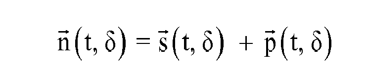

Um die Geschwindigkeit des Kolbens E zu erhalten, wird die Zeitableitung des Nadelvektors gebildet: 
Bei hoher zeitlicher Auflösung und damit sehr kleinem Δt kann für die Ermittlung der Geschwindigkeit mit ausreichender Genauigkeit mit dem Differenzenquotienten gerechnet werden. 
Die Variation des Höhenwinkels δ stellt eine Möglichkeit dar, den Nadelherausstand und gleichzeitig den Hub zu ändern.The variation of the elevation angle δ represents a possibility to change the Nadelausausstand and simultaneously the stroke.
Bei dem Beispiel 14.3 ist Folgendes vorgesehen: Pleuelfester Gleitstift ist drehbar wandfest gelagert, Kurbel gleitet auf Pleuellängsachse. Die Eigenschaft einer Kurbel mit Gleithülse B kann bei kleiner Exzentrizität e beispielsweise auch durch ein Langloch-Pleuelauge mit parallelen Gleitflächen gebildet werden, in welchem eine seitlich spielfrei passende Zylinderscheibe mit einer Exzentrizität e um den Punkt A gleitend rotiert, wobei die Lastseite entsprechend wechselt.In example 14.3, the following is provided: Pile-proof sliding pin is rotatably fixed to the wall, crank slides on the longitudinal axis of the connecting rod. The property of a crank with sliding sleeve B can be formed at a small eccentricity e, for example, by a slot connecting rod with parallel sliding surfaces in which a laterally free matching cylinder disc with an eccentricity e to the point A slidably rotates, the load side changes accordingly.
Das Bezugskoordinatensystem hat seinen Ursprung in der Symmetrieachse der Motorwelle, dem Punkt A. Der Vektor e stellt die Verbindung zwischen dem Punkt A und dem Mittelpunkt der Hülse B auf der Kurbelscheibe dar. Sein Betrag sei e und zeitlich konstant. Der Vektor l verbindet den Gleitstift C mit dem oberen Pleuelauge D. Der Betrag von l sei berechnet als die Differenz aus l und l1 und zeitlich konstant. Der Vektor d stellt die Koordinaten des Gleitstifts C dar. Er ist zeitlich konstant, sein Betrag sei d. Er schließt den Höhenwinkel δ mit der Abszisse ein. Der Winkel δ sei einstellbar, aber ebenfalls als zeitlich konstant anzusehen. Er stellt die Variable für die Hubverstellung dar. Der Vektor p zeigt auf die Koordinaten des oberen Pleuelauges D. Der Vektor s stellt die Längsachse der Schubstange DE dar, welche das obere Pleuelauge D mit dem Kolben E verbindet. Der Kolben, welcher die Nadel aufnehmen soll, besitzt eine feste x-Koordinate, lediglich die y-Koordinate ist zeitvariant. Der Vektor n zeigt dabei auf die Koordinaten des Kolbens bezüglich des Koordinatensystems.The reference coordinate system has its origin in the axis of symmetry of the motor shaft, the point A. The vector e represents the connection between the point A and the center of the sleeve B on the crank disk. Its magnitude is e and time constant. The vector l connects the sliding pin C with the upper connecting rod eye D. The amount of l is calculated as the difference between l and l 1 and constant over time. The vector d represents the coordinates of the sliding pin C. It is constant in time, its magnitude is d. It includes the elevation angle δ with the abscissa. The angle δ is adjustable, but also considered to be constant over time. It represents the variable for the stroke adjustment. The vector p points to the coordinates of the upper connecting rod D. The vector s represents the longitudinal axis of the push rod DE, which connects the upper connecting rod eye D with the piston E. The piston which is to receive the needle has a fixed x-coordinate, only the y-coordinate is time-variant. The vector n points to the coordinates of the piston with respect to the coordinate system.
Somit lässt sich der Vektor l unter Verwendung der bekannten Werte l und ll errechnen: 
Es ergibt sich der Ortsvektor p des oberen Pleuelauges D im Koordinatensystem: 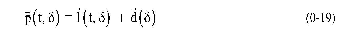
Der Lagevektor s der Schubstange bildet mit der Vertikalen durch den Punkt E und mit der Horizontalen durch den Punkt D ein rechtwinkliges Dreieck und kann deshalb mit dem Satz des Pythagoras unter Verwendung der bekannten Länge ls und der festen x-Position des Punkts E ermittelt werden, wobei im Folgenden px(t) und py(t) die zeitveränderlichen Komponenten des Pleuelvektors p und x einen frei wählbaren Wert für den horizontalen Versatz des Kolbens von der (x = 0)-Bezugslage d + (l - l1) darstellen: 
Als Summe der Vektoren p und s ergibt sich schließlich der Vektor n des Kolbens im Koordinatensystem: 

Der nicht erneut dargestellte Ortsvektor e sowie der Geschwindigkeitsvektor v des Kolbens und der Winkelvektor ϕ lassen sich wie bei dem Beispiel 14.1 ermitteln, siehe dort.The position vector e not shown again as well as the velocity vector v of the piston and the angle vector φ can be determined as in Example 14.1, see there.
Bei dem Beispiel 14.4 ist Folgendes vorgesehen: Pleuelfester Gleitstift ortsfest drehbar in Gehäusewand, Motorwelle gleitet in Gehäusenut.In example 14.4 the following is provided: Pile-proof sliding pin stationary rotatable in housing wall, motor shaft slides in housing groove.
Die Nut in der Gehäusewand sei verstellbar und verlaufe unter einem Winkel δ bezüglich der negativen Abszisse. Das Bezugskoordinatensystem hat seinen Ursprung im Gleitstift, dem Punkt C. Der Vektor e stellt die Verbindung zwischen dem Punkt A und dem unteren Pleuelauge, Punkt B, dar. Sein Betrag sei e und zeitlich konstant. Der Vektor l stellt die schematische Reduktion des Pleuels dar und verbindet den Punkt B über den Gleitstift C hinweg mit dem Punkt D. Der Betrag von l sei l, der vom Abstand BC sei l1, beide seien zeitlich konstant. Der Vektor d stellt die invertierten Koordinaten der Motorwelle A dar und besitzt somit positive Komponenten, sein Betrag sei d und zeitlich veränderlich. Er schließt den Höhenwinkel δ mit der Abszisse ein. Der Winkel δ sei einstellbar, aber als zeitlich konstant anzusehen. Er stellt die Variable für die Hubverstellung dar. Der Vektor p zeigt auf die Koordinaten des oberen Pleuelauges D. Der Vektor s stellt die Längsachse der Schubstange DE dar, welche das obere Pleuelauge D mit dem Kolben E verbindet. Der Kolben, welcher unter anderem die Nadel aufnehmen soll, besitzt eine feste x-Koordinate, lediglich die y-Koordinate ist zeitvariant. Der Vektor n zeigt dabei auf die Koordinaten des Kolbens bezüglich des Koordinatensystems.The groove in the housing wall is adjustable and run at an angle δ with respect to the negative abscissa. The reference coordinate system has its origin in the sliding pin, the point C. The vector e represents the connection between the point A and the lower connecting rod eye, point B. Its magnitude is e and temporally constant. The vector l represents the schematic reduction of the connecting rod and connects the point B over the sliding pin C away with the point D. The amount of l is l, the distance BC is l 1 , both are temporally constant. The vector d represents the inverted coordinates of the motor shaft A and thus has positive components, its magnitude is d and time variable. It includes the elevation angle δ with the abscissa. The angle δ is adjustable, but considered constant over time. It represents the variable for the stroke adjustment. The vector p points to the coordinates of the upper connecting rod D. The vector s represents the longitudinal axis of the push rod DE, which connects the upper connecting rod eye D with the piston E. The piston, which among other things is to receive the needle, has a fixed x-coordinate, only the y-coordinate is time-variant. The vector n points to the coordinates of the piston with respect to the coordinate system.
Wegen der Ähnlichkeit zur Ausführung 14.1 werden hier lediglich die abweichenden Vektoren dargestellt. Die Verhältnisse am Dreieck ABC sind unverändert geblieben. Jedoch unterscheidet sich der Vektor p: 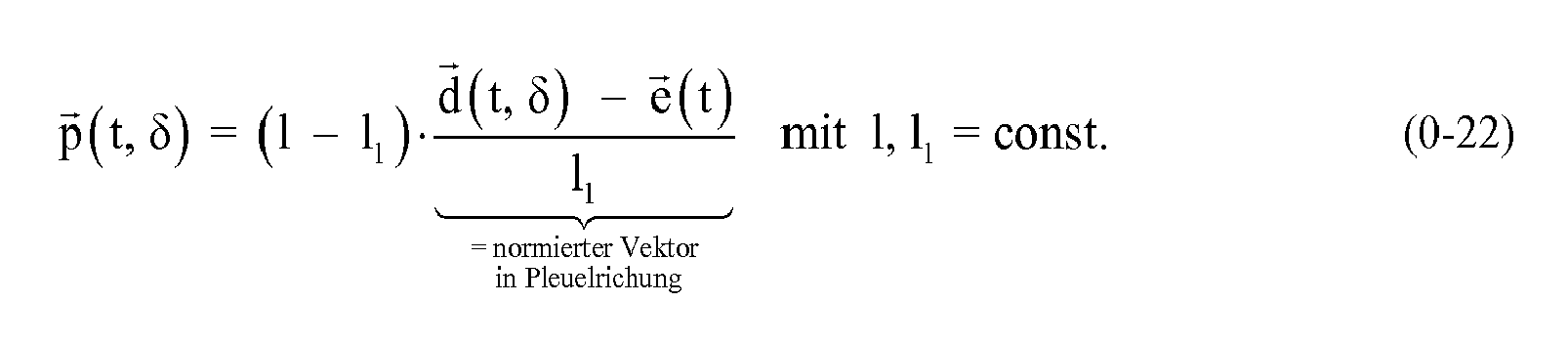
Damit ergeben sich auch Änderungen an den von p abhängigen Vektoren. Der Lagevektor s der Schubstange bildet mit der Vertikalen durch den Punkt E und mit der Horizontalen durch den Punkt D ein rechtwinkliges Dreieck und kann deshalb mit dem Satz des Pythagoras unter Verwendung der bekannten Länge ls und der festen x-Position des Punktes E ermittelt werden, wobei im Folgenden px(t) und py(t) die zeitveränderlichen Komponenten des Pleuelvektors p und x einen frei wählbaren Wert für den horizontalen Versatz des Kolbens von der x-Bezugslage l - l1 darstellen: 
Als Summe der Vektoren p und s ergibt sich schließlich der Vektor n des Kolbens im Koordinatensystem: 

Die nicht erneut dargestellten Ortsvektoren e, l und d sowie der Geschwindigkeitsvektor v des Kolbens und der Winkelvektor ϕ, lassen sich wie bei der Ausführung 1 ermitteln, siehe dort.The position vectors e, l and d not shown again as well as the velocity vector v of the piston and the angle vector φ, can be determined as in the
Bei dem Beispiel 14.5 liegt die Fesselung des Pleuels außerhalb der Antriebs-Abtriebs-Verbindung. In allen anderen Punkten gilt das zu Ausführung 14.3 Gesagte entsprechend.In Example 14.5, the tie of the connecting rod is outside the drive-output connection. In all other points, what has been said about execution 14.3 applies accordingly.
Der hier zeitlich konstante Vektor d, welcher vom Koordinatenursprung A zum Gleitstift C zeigt, ergibt sich zu: 
Somit lässt sich der Vektor l unter Verwendung seines Betrags l errechnen: 
Es ergibt sich der Ortsvektor p des oberen Pleuelauges D im Koordinatensystem: 
Der Lagevektor s der Schubstange bildet mit der Vertikalen durch den Punkt E und mit der Horizontalen durch den Punkt D ein rechtwinkliges Dreieck und kann deshalb mit dem Satz des Pythagoras unter Verwendung der bekannten Länge ls und der festen x-Position des Punkts E ermittelt werden, wobei im Folgenden px(t) und py(t) die zeitveränderlichen Komponenten des Pleuelvektors p und x einen frei wählbaren Wert für den horizontalen Versatz des Kolbens von der x-Bezugslage l - d darstellen: 
Als Summe der Vektoren p und s ergibt sich schließlich der Vektor n des Kolbens im Koordinatensystem: 

Der nicht erneut dargestellte Ortsvektor e sowie der Geschwindigkeitsvektor v des Kolbens und der Winkelvektor ϕ, lassen sich wie bei der Ausführung 14.1 ermitteln, siehe dort.The position vector e not shown again as well as the velocity vector v of the piston and the angle vector φ, can be determined as in the embodiment 14.1, see there.
Bei dem Beispiel 14.6 liegt die Fesselung des Pleuels außerhalb der Antriebs-Abtriebs-Verbindung. In allen anderen Punkten gilt das zur Ausführung 14.1 Gesagte (vgl.
Der in seinem Betrag zeitveränderliche Vektor d, welcher vom Koordinatenursprung A zum Gleitstift C zeigt, ergibt sich unter Anwendung des Sinussatzes für beliebige Dreiecke und der Beziehung für die Innenwinkelsumme zu: 

Somit lässt sich der Vektor l unter Verwendung seines Betrags l und des mit l1 bekannten festen Abstands BC errechnen: 
Es ergibt sich der Ortsvektor p des oberen Pleuelauges D im Koordinatensystem: 
Der Lagevektor s der Schubstange bildet mit der Vertikalen durch den Punkt E und mit der Horizontalen durch den Punkt D ein rechtwinkliges Dreieck und kann deshalb mit dem Satz des Pythagoras unter Verwendung der bekannten Länge ls und der festen x-Position des Punkts E ermittelt werden, wobei im Folgenden px(t) und py(t) die zeitveränderlichen Komponenten des Pleuelvektors p und x einen frei wählbaren Wert für den horizontalen Versatz des Kolbens von der x-Bezugslage e + l darstellen: 
Als Summe der Vektoren p und s ergibt sich schließlich der Vektor n des Kolbens im Koordinatensystem: 

Der nicht erneut dargestellte Ortsvektor e sowie der Geschwindigkeitsvektor v des Kolbens und der Winkelvektor ϕ, lassen sich wie bei der Ausführung 1 ermitteln, siehe dort.The position vector e not shown again as well as the velocity vector v of the piston and the angle vector φ, can be determined as in the
Das Prinzip des Beispiels 14.7 beruht darauf, dass der Gleitstift C die Eigenschaften bzw. Zwangsbedingungen der ersten Ausführung anteilig mit der zweiten kombiniert.The principle of Example 14.7 is based on the sliding pin C proportionally combining the characteristics or constraints of the first embodiment with the second one.
Um dies zu bewirken, existiert ein Hilfspleuel B1C bzw. b, welches die Gleitbewegung des Gleitstifts C erzwingt. Der Gleitstift C gleitet sowohl in einer Nut in der Wand, die bezüglich der Nulllage unter einem Höhenwinkel δ längs in Richtung AC verläuft, als auch auf der Längsachse des Pleuels, zum Beispiel in einer Nut im Pleuel. Der Winkel δ sei einstellbar, aber als zeitlich konstant anzusehen. Er stellt die Variable für die Hubverstellung dar. Das Bezugskoordinatensystem hat seinen Ursprung in der Symmetrieachse der Motorwelle, dem Punkt A. Der Vektor e stellt die Verbindung zwischen dem Punkt A und dem Mittelpunkt des unteren Pleuelauges B des Hauptpleuels l dar. Sein Betrag sei e und zeitlich konstant. Der Vektor e1 stellt die Verbindung zwischen dem Punkt A und dem Mittelpunkt des unteren Pleuelauges B1 des Hilfspleuels b dar. Sein zeitlich konstanter Betrag sei e1, ein prozentualer und konstruktiv festzulegender Anteil von e. Der Vektor b stellt schematisch ein Hilfspleuel dar, sein Betrag sei b und errechnet sich zu b = e + l1 - e1. Der Vektor d stellt die Koordinaten des Gleitstifts C dar, sein Betrag sei d und zeitlich veränderlich. Er schließt den oben genannten Höhenwinkel δ mit der Abszisse ein. Der Vektor l stellt die schematische Reduktion des Hauptpleuels dar und verbindet den Punkt B über den Gleitstift C hinweg mit dem Punkt D. Der Betrag von l sei l. Der Vektor p zeigt auf die Koordinaten des oberen Hauptpleuelauges D. Der Vektor s stellt die Längsachse der Schubstange DE dar, welche das obere Hauptpleuelauge D mit dem Kolben E verbindet, sein Betrag sei ls. Der Kolben E, welcher unter anderem die Nadel aufnehmen soll, besitzt eine feste x-Koordinate, lediglich die y-Koordinate ist zeitvariant. Der Vektor n zeigt dabei auf die Koordinaten des Kolbens E bezüglich des Koordinatensystems.To effect this, there exists an auxiliary connecting rod B 1 C or B, which forces the sliding movement of the sliding pin C. The sliding pin C slides both in a groove in the wall, which runs in the direction of the zero position at an elevation angle δ longitudinally in the direction AC, as well as on the longitudinal axis of the connecting rod, for example in a groove in the connecting rod. The angle δ is adjustable, but considered constant over time. It represents the variable for the stroke adjustment. The reference coordinate system has its origin in the axis of symmetry of the motor shaft, the point A. The vector e represents the connection between the point A and the center of the lower connecting rod B of Hauptpleuels l and constant over time. The vector e 1 represents the connection between the point A and the center of the lower connecting rod B 1 of the auxiliary connecting rod b. Its temporally constant amount is e 1 , a percentage and constructively determined proportion of e. The vector b schematically represents an auxiliary connecting rod, its magnitude is b and is calculated as b = e + l 1 -e 1 . The vector d represents the coordinates of the sliding pin C, its magnitude is d and time-varying. It includes the above-mentioned elevation angle δ with the abscissa. The vector I represents the schematic reduction of the main conductor and connects the point B over the sliding pin C away with the point D. The amount of l is l. The vector p points to the coordinates of the upper Hauptpleuelauges D. The vector s represents the longitudinal axis of the push rod DE, which connects the upper Hauptpleuelauge D with the piston E, its amount is l s . The piston E, which is to receive the needle among other things, has a fixed x-coordinate, only the y-coordinate is time-variant. The vector n points to the coordinates of the piston E with respect to the coordinate system.
Wegen des größeren baulichen Aufwands - es sind mehr bewegliche Teile und damit Fehlerquellen im System - kann die Realisierbarkeit im Einzelfall schwieriger als bei den Beispielen 14.1 bis 14.4 sein.Because of the greater structural complexity - there are more moving parts and thus sources of error in the system - the feasibility in individual cases can be more difficult than in Examples 14.1 to 14.4.
Die Auswirkung einer zeitlich konstanten, nicht verschwindenden Phasenbeziehung λ zwischen den Vektoren e und e1 wurde hier nicht untersucht, könnte sich jedoch als vorteilhaft erweisen. Ebenso eine andere Länge b für das Hilfspleuel. Der erstgenannte Ansatz ist in Beispiel 14.7 veranschaulicht. Hierbei sind für λ sowohl positive als auch negative Werte denkbar.The effect of a temporally constant, non-vanishing phase relationship λ between the vectors e and e 1 was not investigated here, but could prove to be advantageous. Likewise another length b for the auxiliary connecting rod. The former approach is illustrated in Example 14.7. Both positive and negative values are conceivable for λ.
Der in seinem Betrag zeitveränderliche Vektor d, welcher vom Koordinatenursprung A zum Gleitstift C zeigt, ergibt sich in Anlehnung an die Ausführung 1 unter Anwendung des Sinussatzes für beliebige Dreiecke, der Beziehung für die Innenwinkelsumme sowie der Einbeziehung einer nicht verschwindenden Phasenbeziehung λ zu: 
mit e1, b, δ = const. 
with e 1 , b, δ = const.
Somit lässt sich der Vektor l ähnlich zur Ausführung 2 unter Verwendung seines Betrags l errechnen: 
Die nicht erneut dargestellten Ortsvektoren e, p, s und n sowie der Geschwindigkeitsvektor v des Kolbens und der Winkelvektor ϕ.The position vectors e, p, s and n, not shown again, as well as the speed vector v of the piston and the angle vector φ.
Im Unterschied zu Ausführung 14.2 gleitet bei dem Beispiel 14.8 eine um den Betrag q parallel zur Pleuellängsachse versetzte Hilfsachse in einer drehbar gelagerten, wandfesten Hülse. Damit gehen beide Ausführungen bei q = 0 ineinander über. Die schematischen Vektorbeziehungen sind in Beispiel 14.8 dargestellt.In contrast to embodiment 14.2 slides in the example 14.8 a by the amount q parallel to the connecting rod longitudinal axis offset auxiliary axis in a rotatably mounted, wall-mounted sleeve. Thus, both versions go into each other at q = 0. The schematic vector relationships are shown in Example 14.8.
Bei dieser Ausführung war die Modellbildung ein wenig aufwendiger. Stellt man sich jedoch den Pleuel reduziert auf ein Rechteck vor, welches auf einer Gleitrolle C mit infinitesimalem Durchmesser aufliegt, so vereinfacht sich die Vektorerstellung.In this embodiment, the modeling was a little more expensive. However, if one imagines the conrod reduced to a rectangle, which rests on a caster C with infinitesimal diameter, so simplifies the vector creation.
Es wird angenommen, dass die Vektoren e, d und damit y sowie deren Beträge jederzeit bekannt seien, vgl. hierzu Beispiel 14.8. Der Betrag q des Vektors q sei ebenfalls bekannt, denn q stellt den konstruktiv gewünschten Parallelversatz dar. Die Vektoren y, q und z spannen ein rechtwinkliges Dreieck auf. Somit kann die Arcussinusfunktion verwendet werden, um den Winkel ζ zu berechnen. Dieser tritt wegen der Parallelität von z und 1 als Wechselwinkel ebenfalls zwischen y und l auf. Damit muss, um den Vektors l zu erhalten, abschließend der Vektor y auf die Länge l normiert, um ζ im positiven Sinn gedreht und mit dem Betrag l skaliert werden. Der so erhaltene Vektor l stellt wie bei den Ausführungn zuvor die Verbindung BD her. Die übrigen Verhältnisse und Vektoren berechnet man wie bereits in der Ausführung 14.1.It is assumed that the vectors e, d and thus y as well as their amounts are known at all times, cf. see example 14.8. The magnitude q of the vector q is also known, because q represents the structurally desired parallel offset. The vectors y, q and z span a right-angled triangle. Thus, the arcsine function can be used to calculate the angle ζ. This occurs because of the parallelism of z and 1 as a change angle also between y and l. Thus, in order to obtain the vector l, the vector y must be normalized to the length l, rotated by ζ in a positive sense, and scaled by the amount l. The vector I thus obtained produces the compound BD in advance as in the embodiments. The remaining ratios and vectors are calculated as in the implementation 14.1.
Für den Vektor d gilt, dass bei δ = 0 der Vektor mit der positiven Abszisse einen Winkel δ0 einschließt. Seine Koordinaten sind in diesem Fall (d, -q), wobei q aus der konstruktiven Vorgabe und d aus der Berechnung d = e + l1 erhalten werden. Für einen Höhenwinkel δ, der für eine superponierte Hubverstellung anzupassen ist auf eine günstige Arbeitslage, muss der so erhaltene Vektor d0(δ0) mithilfe der 2D-Drehmatrix in der Ebene gedreht werden, man erhält den Vektor d(δ0+δ). Die Koordinaten nach einer Drehung seien (d*, -q*), was in 
Man erhält den Vektor y zu: 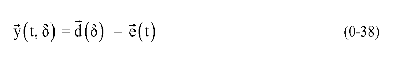
Damit lässt sich der Vektor l ermitteln: 
mit 
With
Die nicht erneut dargestellten Ortsvektoren e, p, s und n sowie der Geschwindigkeitsvektor v des Kolbens und der Winkelvektor ϕ, lassen sich wie bei Ausführung 1 ermitteln, siehe dort.The position vectors e, p, s and n not shown again as well as the velocity vector v of the piston and the angle vector φ, can be determined as in
Zudem kann die Forderung nach einem konstanten Parallelversatz q aufgegeben werden. Dieser wäre dann eine Funktion q(|z(t)|). Denkbar ist eine zur Pleuellängsachse schräg-lineare oder auch eine frei geformte Gleitnut im Pleuel. Die analytische Lösung ist zum Beispiel mit folgendem Vorgehen möglich: Der Betrag von y sei für jedes t bekannt bzw. berechenbar. Man nehme den Betrag von z und damit q(z) zunächst als bekannt an, dann lässt sich über den Satz des Pythagoras y2 = q2(|z|) + |z|2 formulieren. Für die Ermittlung von z müssen folgende Bedingungen Beachtung finden, da eventuell mehrere Lösungen erhalten werden, zum Beispiel als Nullstellen eines Polynoms. 
Falls diese Beziehung nach |z| aufgelöst oder numerisch gelöst werden kann, ist die Ermittlung des Winkels ζ über die arccos-Funktion möglich. Das weitere Vorgehen entspricht dem in der Gleichung (0-39).If this relationship follows | z | resolved or solved numerically, the determination of the angle ζ is possible via the arccos function. The further procedure corresponds to that in the equation (0-39).
Eine Erweiterung dessen um das Konzept aus der Ausführung 7 ist zusätzlich denkbar, wurde hier jedoch nicht untersucht. Dabei würde der Gleitstift C mittels eines Hilfspleuels, welches durch eine Hilfskurbel e1 mit fester Phasenbeziehung λ zur Hauptkurbel e getrieben wird, in einer Nut in der Gehäusewand und / oder in der Pleuelnut geführt werden. Die jeweilige Nut könnte statt einer geraden eine freie Form aufweisen.An extension of this to the concept of the
Das Beispiel 14.9 (vgl.
Hier wird angenommen, dass beide Antriebskurbeln über eine Verzahnung miteinander verbunden sind und eine beliebige, aber zeitlich konstante Phase λ (= Drehversatz) vorliegt. Das Übersetzungsverhältnis n der Zahnradpaarung z1 und z2 muss nicht zwingend Eins betragen, dies vereinfacht jedoch die Mechanik und die Konstruktion und wird hier angenommen. Bei einer Unter- oder Übersetzung der Antriebsdrehzahl erhält man eine mit entsprechender Periodik wechselnde Dynamik des Kolbens, was vorteilhaft bezüglich der Schwingungsdynamik der Haut sein kann. Zusätzlich ist für den Fall n ≠ 1 der Kurbelradius unbedingt kleiner als der Kopfkreisdurchmesser der Zahnräder zu wählen, um eine Kollision der Punkte B und C zu vermeiden, wie man in der Darstellung erkennt.Here it is assumed that both drive cranks are connected to each other via a toothing and an arbitrary, but temporally constant phase λ (= rotational offset) is present. The gear ratio n of the gear pair z 1 and z 2 need not necessarily be one, but this simplifies the mechanics and the design and is assumed here. When the drive speed is under or translated, the dynamics of the piston changing with corresponding periodicity are obtained, which can be advantageous with respect to the vibration dynamics of the skin. In addition, for the case n ≠ 1, the crank radius is necessarily smaller than the tip circle diameter of the gears to select to avoid a collision of the points B and C, as seen in the illustration.
Für die Kurbeldrehwinkel ϕ und δ und die Zähnezahl z1 und z2 gilt ohne Ausschluss der Allgemeinheit: 
Der hier zeitlich veränderliche Gleitstiftvektor d, welcher vom Koordinatenursprung A zum Umlenkstift C zeigt, ergibt sich als Summe aus dem Umlenkstift-Kurbelvektor r und dem konstanten Abstandsvektor der Kurbelachse a unter Einbeziehung der Phase λ zu: 
Somit lässt sich der Vektor l unter Verwendung seines Betrags l errechnen: 
Es ergibt sich der Ortsvektor p des oberen Pleuelauges D im Koordinatensystem: 
Der Lagevektor s der Schubstange bildet mit einer Vertikalen durch den Punkt D und mit der Abszisse durch den Punkt E ein rechtwinkliges Dreieck und kann deshalb mit dem Satz des Pythagoras unter Verwendung der bekannten Länge ls ermittelt werden, wobei im Folgenden px(t) und py(t) die zeitveränderlichen Komponenten des Pleuelvektors p darstellen: 
Als Summe der Vektoren p und s ergibt sich schließlich der Vektor n des Kolbens E im Koordinatensystem: 

Der nicht erneut dargestellte Ortsvektor e sowie der Geschwindigkeitsvektor v des Kolbens und der Winkelvektor ϕ, lassen sich wie bei der Ausführung 1 ermitteln, siehe dort.The position vector e not shown again as well as the velocity vector v of the piston and the angle vector φ, can be determined as in the
Das Beispiel 14.9 aus
Nachfolgend werden weitere Aspekte der Hubeinstellung mit kompensiertem und einstellbarem Nadelherausstand bei hoher Stechgeschwindigkeit näher erläutert. Es wurde das Beispiel 14.5 ausgewählt, da hier die Hubeinstellung mit Kompensation gut umsetzbar ist.In the following, further aspects of the stroke adjustment with compensated and adjustable needle deflection at high puncturing speed are explained in more detail. Example 14.5 has been selected, since here the stroke adjustment with compensation can be easily implemented.
Bei dem Beispiel werden im Vergleich zum Beispiel 14.2 die Rolle des Gleitstifts C und der Kurbel B vertauscht. Zusätzlich wurde zugunsten einer alternierenden Stechfrequenz (siehe weiter unten) ein Höhenwinkel δ = 90° gewählt und auf den seitlichen Versatz l - d + x (Variante 5) verzichtet, was die schematische Darstellung in
Die Hubeinstellung wird bei dieser Gestaltungsvariante durch eine Veränderung des Abstands zwischen dem Pleueldrehpunkt C und der Motorwelle A realisiert, wodurch sich der von den durch C laufenden Tangenten an den Kurbelkreis eingeschlossene Winkel und damit die Lage des unteren (hinteren) Totpunkts des Nadelkolbens E ändern.The stroke adjustment is realized in this design variant by changing the distance between the connecting rod pivot point C and the motor shaft A, whereby the angle enclosed by the C tangents to the crank circle angle and thus the position of the lower (rear) dead center of the needle piston E change.
Anhand der schematischen Darstellung in
Für die analytische Ermittlung des Hubs in Abhängigkeit vom Pleuelstiftabstand (PSA) wird auf
Dabei kann für das System im hinteren Totpunkt E über den Strecken AB und AC ein rechtwinkliges Dreieck mit einem gemeinsamen Innenwinkel α aufgespannt werden, sodass gilt: 
Daraus ergibt sich h zu 
Des Weiteren erhält man für die Summe der Strecken a (= AC) und b (=CE) unter Anwendung des Satzes des Pythagoras folgende Beziehung: 
Dabei ist lP die Länge des Pleuels, h die Höhe und lS die Länge der Schubstange. Wird (0-48) in (0-49) eingesetzt, so kann für die konstruktiv festgelegten Größen e, lP und lS eine Abhängigkeit des Hubs von der veränderlichen Größe PSA angegeben werden. 

In einer Ausführung wurden zum Beispiel ein Kurbelkreisradius e = 2 mm, eine Pleuellänge lP = 15 mm und für die Schubstange eine Länge lS = 11 mm gewählt.In one embodiment, for example, a crank circle radius e = 2 mm, a connecting rod length l P = 15 mm and for the push rod a length l S = 11 mm were selected.
Die in der vorstehenden Beschreibung, den Ansprüchen sowie der Zeichnung offenbarten Merkmale können sowohl einzeln als auch in beliebiger Kombination für die Verwirklichung der verschiedenen Ausführungen von Bedeutung sein.The features disclosed in the above description, the claims and the drawings may be important both individually and in any combination for the realization of the various embodiments.
Claims (15)
Priority Applications (1)
| Application Number | Priority Date | Filing Date | Title |
|---|---|---|---|
| EP14172119.1A EP2954925A1 (en) | 2014-06-12 | 2014-06-12 | Handheld device for repeated puncturing of a human or animal skin and drive module |
Applications Claiming Priority (1)
| Application Number | Priority Date | Filing Date | Title |
|---|---|---|---|
| EP14172119.1A EP2954925A1 (en) | 2014-06-12 | 2014-06-12 | Handheld device for repeated puncturing of a human or animal skin and drive module |
Publications (1)
| Publication Number | Publication Date |
|---|---|
| EP2954925A1 true EP2954925A1 (en) | 2015-12-16 |
Family
ID=50942115
Family Applications (1)
| Application Number | Title | Priority Date | Filing Date |
|---|---|---|---|
| EP14172119.1A Withdrawn EP2954925A1 (en) | 2014-06-12 | 2014-06-12 | Handheld device for repeated puncturing of a human or animal skin and drive module |
Country Status (1)
| Country | Link |
|---|---|
| EP (1) | EP2954925A1 (en) |
Cited By (7)
| Publication number | Priority date | Publication date | Assignee | Title |
|---|---|---|---|---|
| US9629991B1 (en) | 2016-06-08 | 2017-04-25 | Eclipse Aesthetics, LLC | Disposable radio frequency needle cartridges having absorbing containment barriers |
| US9636491B1 (en) | 2016-06-08 | 2017-05-02 | Eclipse Aesthetics, LLC | Disposable needle cartridges having absorbing contaminant barriers |
| EP3228349A1 (en) | 2016-04-05 | 2017-10-11 | Werner Arnold | Stroke adjustment device for l-shaped microneedle device |
| US10220195B2 (en) | 2016-06-08 | 2019-03-05 | Eclipse Medcorp, Llc | Radio frequency needling device for use with disposable needle cartridges |
| DE102018113210A1 (en) | 2018-06-04 | 2019-12-05 | PROMEDIA Gesundheitspartner GmbH | Drive for microneedle device and microneedle device |
| EP4260897A1 (en) * | 2022-04-14 | 2023-10-18 | MT.DERM GmbH | Driving device for a hand tool for the local piercing of a skin and hand-held device |
| EP4260896A1 (en) * | 2022-04-14 | 2023-10-18 | MT.DERM GmbH | Handheld device for the local puncturing of human or animal skin |
Citations (8)
| Publication number | Priority date | Publication date | Assignee | Title |
|---|---|---|---|---|
| GB1587519A (en) * | 1977-12-16 | 1981-04-08 | Langley K | Tattooing instrument |
| DE4331442A1 (en) * | 1993-09-16 | 1995-03-23 | Stefan Schuh | Tattooing apparatus |
| DE29919199U1 (en) | 1999-10-22 | 2000-01-20 | MediUm-TECH GmbH, 12681 Berlin | Tattoo and / or permanent make-up paint hand tool |
| EP1495782A1 (en) | 2003-07-08 | 2005-01-12 | MediUm-TECH Medizingeräte GmbH | Tattooing and permanent make-up device |
| DE202004016876U1 (en) * | 2004-11-02 | 2005-07-21 | Grube, Andreas | Needle drive for a tattooing machine has a cam with an eccentric part connected to the motor shaft and a connection rod connected to the rear side of the cam |
| CN202236855U (en) | 2011-06-29 | 2012-05-30 | 广州梓煊美容器材有限公司 | Adjustable needle pitch eyebrow tattooing pen |
| US8522647B1 (en) * | 2011-08-05 | 2013-09-03 | Alan B. Dixon | Eccentric gear for tattoo machine for adjusting the needle throw |
| WO2014065726A1 (en) * | 2012-10-25 | 2014-05-01 | Ink Machines Sweden Ab | Tattoo machine and method of operating a tattoo machine |
-
2014
- 2014-06-12 EP EP14172119.1A patent/EP2954925A1/en not_active Withdrawn
Patent Citations (8)
| Publication number | Priority date | Publication date | Assignee | Title |
|---|---|---|---|---|
| GB1587519A (en) * | 1977-12-16 | 1981-04-08 | Langley K | Tattooing instrument |
| DE4331442A1 (en) * | 1993-09-16 | 1995-03-23 | Stefan Schuh | Tattooing apparatus |
| DE29919199U1 (en) | 1999-10-22 | 2000-01-20 | MediUm-TECH GmbH, 12681 Berlin | Tattoo and / or permanent make-up paint hand tool |
| EP1495782A1 (en) | 2003-07-08 | 2005-01-12 | MediUm-TECH Medizingeräte GmbH | Tattooing and permanent make-up device |
| DE202004016876U1 (en) * | 2004-11-02 | 2005-07-21 | Grube, Andreas | Needle drive for a tattooing machine has a cam with an eccentric part connected to the motor shaft and a connection rod connected to the rear side of the cam |
| CN202236855U (en) | 2011-06-29 | 2012-05-30 | 广州梓煊美容器材有限公司 | Adjustable needle pitch eyebrow tattooing pen |
| US8522647B1 (en) * | 2011-08-05 | 2013-09-03 | Alan B. Dixon | Eccentric gear for tattoo machine for adjusting the needle throw |
| WO2014065726A1 (en) * | 2012-10-25 | 2014-05-01 | Ink Machines Sweden Ab | Tattoo machine and method of operating a tattoo machine |
Cited By (9)
| Publication number | Priority date | Publication date | Assignee | Title |
|---|---|---|---|---|
| EP3228349A1 (en) | 2016-04-05 | 2017-10-11 | Werner Arnold | Stroke adjustment device for l-shaped microneedle device |
| US9629991B1 (en) | 2016-06-08 | 2017-04-25 | Eclipse Aesthetics, LLC | Disposable radio frequency needle cartridges having absorbing containment barriers |
| US9636491B1 (en) | 2016-06-08 | 2017-05-02 | Eclipse Aesthetics, LLC | Disposable needle cartridges having absorbing contaminant barriers |
| US10220195B2 (en) | 2016-06-08 | 2019-03-05 | Eclipse Medcorp, Llc | Radio frequency needling device for use with disposable needle cartridges |
| US12048823B2 (en) | 2016-06-08 | 2024-07-30 | Crown Laboratories, Inc. | Needling device for use with disposable needle cartridges |
| DE102018113210A1 (en) | 2018-06-04 | 2019-12-05 | PROMEDIA Gesundheitspartner GmbH | Drive for microneedle device and microneedle device |
| EP3578225A1 (en) | 2018-06-04 | 2019-12-11 | Promedia Gesundheitspartner GmbH | Microneedle device and drive for microneedle device |
| EP4260897A1 (en) * | 2022-04-14 | 2023-10-18 | MT.DERM GmbH | Driving device for a hand tool for the local piercing of a skin and hand-held device |
| EP4260896A1 (en) * | 2022-04-14 | 2023-10-18 | MT.DERM GmbH | Handheld device for the local puncturing of human or animal skin |
Similar Documents
| Publication | Publication Date | Title |
|---|---|---|
| EP2954925A1 (en) | Handheld device for repeated puncturing of a human or animal skin and drive module | |
| DE60317997T2 (en) | lancet | |
| EP2682146B1 (en) | Handheld device for applying tattoo ink or permanent make-up and needle module with adjustable needle penetration depth | |
| EP2954926B1 (en) | Handheld device for the repeated puncturing of human or animal skin | |
| EP1884191B1 (en) | Lancet system | |
| DE2849760C2 (en) | Oscillating surgical saw | |
| EP2954927A1 (en) | Drive module for a handheld device for repeated puncturing of human or animal skin, hand-held device and method | |
| DE4223958A1 (en) | INJECTOR | |
| AT518780B1 (en) | Hand tool for tattooing | |
| EP3363492B1 (en) | Needle module for a drive-managed device for repeated puncturing of human or animal skin and hand-held device | |
| EP3372716B1 (en) | Needling machine | |
| DE10215037B4 (en) | Device for needling a fleece | |
| EP3064251B1 (en) | Skin puncturing tool for local puncturing of human or animal skin and hand-held device | |
| EP2671609B1 (en) | Precise depth capillary needle for repeated introduction of fluids into the skin | |
| EP3725358B1 (en) | Hand-held device and drive system and drive module for a hand-held device for local piercing of human or animal skin | |
| DE102017223714A1 (en) | Device and method for guiding movements of a medical device, in particular a probe | |
| EP3238653A1 (en) | Medical or dental angled handpiece | |
| EP2944348A1 (en) | Capillary injection needle | |
| EP3453309A1 (en) | Endoscopic instrument | |
| DE102005006621B3 (en) | Device to convert rotating or oscillating motion into inversional motion, including in backwards/reverse direction, of articulated joints and articulated chains at typical angles | |
| EP3064250A1 (en) | Skin puncturing tool and puncturing tool for local puncturing of human or animal skin and puncturing tool assembly | |
| DE915049C (en) | Thread cutting machine | |
| AT520572B1 (en) | Electric handheld device | |
| DE102016106042A1 (en) | Drive means for microneedle device in pen form | |
| EP4260897A1 (en) | Driving device for a hand tool for the local piercing of a skin and hand-held device |
Legal Events
| Date | Code | Title | Description |
|---|---|---|---|
| PUAI | Public reference made under article 153(3) epc to a published international application that has entered the european phase |
Free format text: ORIGINAL CODE: 0009012 |
|
| 17P | Request for examination filed |
Effective date: 20150202 |
|
| AK | Designated contracting states |
Kind code of ref document: A1 Designated state(s): AL AT BE BG CH CY CZ DE DK EE ES FI FR GB GR HR HU IE IS IT LI LT LU LV MC MK MT NL NO PL PT RO RS SE SI SK SM TR |
|
| AX | Request for extension of the european patent |
Extension state: BA ME |
|
| RIN1 | Information on inventor provided before grant (corrected) |
Inventor name: SCHERKOWSKI, DIRK |
|
| 17Q | First examination report despatched |
Effective date: 20170828 |
|
| TPAC | Observations filed by third parties |
Free format text: ORIGINAL CODE: EPIDOSNTIPA |
|
| GRAP | Despatch of communication of intention to grant a patent |
Free format text: ORIGINAL CODE: EPIDOSNIGR1 |
|
| INTG | Intention to grant announced |
Effective date: 20180416 |
|
| STAA | Information on the status of an ep patent application or granted ep patent |
Free format text: STATUS: THE APPLICATION HAS BEEN WITHDRAWN |
|
| 18W | Application withdrawn |
Effective date: 20180821 |