EP2954927A1 - Drive module for a handheld device for repeated puncturing of human or animal skin, hand-held device and method - Google Patents
Drive module for a handheld device for repeated puncturing of human or animal skin, hand-held device and method Download PDFInfo
- Publication number
- EP2954927A1 EP2954927A1 EP15171698.2A EP15171698A EP2954927A1 EP 2954927 A1 EP2954927 A1 EP 2954927A1 EP 15171698 A EP15171698 A EP 15171698A EP 2954927 A1 EP2954927 A1 EP 2954927A1
- Authority
- EP
- European Patent Office
- Prior art keywords
- drive
- drive shaft
- movement
- crank pin
- axial direction
- Prior art date
- Legal status (The legal status is an assumption and is not a legal conclusion. Google has not performed a legal analysis and makes no representation as to the accuracy of the status listed.)
- Withdrawn
Links
- 241001465754 Metazoa Species 0.000 title claims abstract description 19
- 238000000034 method Methods 0.000 title claims abstract description 8
- 230000008878 coupling Effects 0.000 claims abstract description 60
- 238000010168 coupling process Methods 0.000 claims abstract description 60
- 238000005859 coupling reaction Methods 0.000 claims abstract description 60
- 230000007246 mechanism Effects 0.000 claims abstract description 22
- 238000006243 chemical reaction Methods 0.000 claims abstract description 21
- 238000013016 damping Methods 0.000 claims description 3
- 238000004891 communication Methods 0.000 claims 1
- 239000002245 particle Substances 0.000 description 7
- 230000008859 change Effects 0.000 description 5
- 238000006073 displacement reaction Methods 0.000 description 5
- 238000013461 design Methods 0.000 description 3
- 239000000463 material Substances 0.000 description 3
- 210000001124 body fluid Anatomy 0.000 description 2
- 239000010839 body fluid Substances 0.000 description 2
- 239000003795 chemical substances by application Substances 0.000 description 2
- 239000002537 cosmetic Substances 0.000 description 2
- 230000000694 effects Effects 0.000 description 2
- 238000010079 rubber tapping Methods 0.000 description 2
- 230000000638 stimulation Effects 0.000 description 2
- 239000000126 substance Substances 0.000 description 2
- WFKWXMTUELFFGS-UHFFFAOYSA-N tungsten Chemical compound [W] WFKWXMTUELFFGS-UHFFFAOYSA-N 0.000 description 2
- 229910052721 tungsten Inorganic materials 0.000 description 2
- 239000010937 tungsten Substances 0.000 description 2
- 241000237942 Conidae Species 0.000 description 1
- 229910000760 Hardened steel Inorganic materials 0.000 description 1
- 238000010521 absorption reaction Methods 0.000 description 1
- 230000001419 dependent effect Effects 0.000 description 1
- 238000005516 engineering process Methods 0.000 description 1
- 210000004709 eyebrow Anatomy 0.000 description 1
- 230000009969 flowable effect Effects 0.000 description 1
- 238000002347 injection Methods 0.000 description 1
- 239000007924 injection Substances 0.000 description 1
- 239000007788 liquid Substances 0.000 description 1
- 238000012423 maintenance Methods 0.000 description 1
- 239000012528 membrane Substances 0.000 description 1
- 229910052751 metal Inorganic materials 0.000 description 1
- 239000002184 metal Substances 0.000 description 1
- 239000003973 paint Substances 0.000 description 1
- 230000008569 process Effects 0.000 description 1
- 230000001681 protective effect Effects 0.000 description 1
- 230000003252 repetitive effect Effects 0.000 description 1
- 230000035939 shock Effects 0.000 description 1
- 239000011343 solid material Substances 0.000 description 1
- 239000012798 spherical particle Substances 0.000 description 1
- 238000009987 spinning Methods 0.000 description 1
- 238000012549 training Methods 0.000 description 1
- 238000012546 transfer Methods 0.000 description 1
Images


Classifications
-
- A—HUMAN NECESSITIES
- A61—MEDICAL OR VETERINARY SCIENCE; HYGIENE
- A61M—DEVICES FOR INTRODUCING MEDIA INTO, OR ONTO, THE BODY; DEVICES FOR TRANSDUCING BODY MEDIA OR FOR TAKING MEDIA FROM THE BODY; DEVICES FOR PRODUCING OR ENDING SLEEP OR STUPOR
- A61M37/00—Other apparatus for introducing media into the body; Percutany, i.e. introducing medicines into the body by diffusion through the skin
- A61M37/0076—Tattooing apparatus
Definitions
- the invention relates to a drive module for a hand-held device for repeatedly piercing a human or animal skin, a hand-held device and methods.
- Devices for local piercing of a human or an animal skin are usually carried out as handsets. Operators may use such hand-held devices to apply a tattoo paint and / or permanent make-up around the skin surface. But also the introduction of cosmetic or medical agents through the skin is possible with such devices by the skin is locally pierced. In addition, such devices can be used without introducing any substance, for example for skin stimulation.
- a handset for local piercing a skin is for example from the document DE 299 19 199 U1 known.
- the known hand-held device has a handle, a drive device and a piercing needle, which is moved with the aid of the drive means in operation relative to a needle nozzle back and forth, wherein at least two detachably interconnected modules are provided, and one of the two modules as a reusable base module is formed with integrated drive device.
- the other of the two modules is a sterilized disposable module into which all components contaminatable by the body fluids of a customer are integrated in the known hand-held device.
- the handset is provided in the form of two modules, one of which, the disposable module, can be exchanged after use while the other module comprising the drive means is reused.
- the hygienic conditions when applying a tattoo and / or permanent make-up are improved, since all parts are exchanged that can potentially be contaminated by the customer's body fluid discharged during the treatment. It is thus avoided that the entire handset must be replaced.
- a drive module for a device for local piercing of a human or an animal skin in which a drive device with which a drive movement can be generated, and provided to the drive means conversion mechanism are provided with the drive rotational movement in a local to a skin piercing lancing device einkoppelbare forward / backward movement is converted, so that a repetitive movement of a piercing needle is made possible.
- the conversion mechanism includes a functional member that performs a tumbling or tilting motion during the motion conversion, thereby providing a driving force for moving a needle piercing the skin locally in the forward and reverse directions.
- the functional component is mounted freewheeling in one embodiment by means of a ball bearing.
- the document CN 201 759 989 U discloses a tattoo machine with a drive device.
- the drive device is formed with an eccentric shaft, which provides a drive movement for a needle.
- the document US 2012/0279330 A1 refers to a transfer mechanism of an eyebrow tattoo machine.
- the device is formed with an eccentric rotary shaft which is coupled to a drive shaft of an engine.
- Another tattooing device is in the document KR 2013/0058843 A disclosed.
- the object of the invention is to provide a drive module for a hand-held device for repeated local piercing of a human or animal skin and a handheld device in which the ease of use is improved during operation of the handset, in particular with regard to disturbing side effects, such as noise or vibration of the handset.
- independent claim 12 relates to a handset. Furthermore, a method for operating a hand-held device for repeated local piercing of a human or animal skin according to independent claim 14 is provided.
- Advantageous embodiments are the subject of dependent subclaims.
- a hand-held device for repeated local piercing of a human or animal skin has a housing with a handle formed thereon.
- the hand-held device which in the case of use for forming tattoos or permanent make-up can also be referred to as tattooing device
- the user grips the handle to guide the hand-held device.
- Other applications include local piercing of the skin for the introduction of a cosmetic or a medicinal agent. But even for the local piercing of human or animal skin without introducing any substance, the handset can be used, for example for skin stimulation.
- a drive device is received, with which via a drive shaft, a rotating drive force is provided.
- an electric motor can be provided.
- a conversion mechanism which is arranged in the housing and adapted to convert the rotary drive movement in a non-rotating drive movement.
- the driving force provided thereby can, for example, be axially aligned, for example parallel to the axis of the drive shaft.
- a lancing device which is accommodated in the housing and has one or more piercing needles, which are arranged on a needle holder.
- the needle holder is formed with a needle plate.
- the needle receptacle is connected to the conversion mechanism and, together with the one or more piercing needles, is repeatedly moved back and forth along a movement path, for example in the axial direction.
- the trajectory may consist of differently shaped sections.
- the conversion mechanism has a crank pin inclined to the axial direction of the drive shaft.
- the crank pin is operatively connected to the drive shaft so as to be displaced in a movement about the axial direction of the drive shaft due to the rotary drive movement.
- the crank pin coupled in the region of a tap to a transversely displaceable transversely to the axial direction of the drive shaft and with the needle-receiving coupling member, such that the movement of the crank pin in a back and forth movement of the coupling member and thus the needle holder transverse to the axial Direction of the drive shaft is converted.
- the forward and backward movement of the coupling member may be performed, for example, as a linear movement.
- this causes the needle holder with the one or more piercing needles to move back and forth transversely to the axial direction of the drive shaft, wherein tips of the piercing needle may be located outside the housing at least in the end position of forward movement.
- a Hubeinstellvorraum with which a stroke of the forward and backward movement of the needle holder is adjustable transversely to the axial direction of the drive shaft.
- the stroke is the axially aligned movement between the reversal points of the linear back and forth movement of the needle receiver or the coupling component coupling thereto. It affects how far the needle tip of the one or more piercing needles is moved forward during operation, whereby in one embodiment the piercing depth in the local area of the skin to be convincedstechenden can be influenced.
- the drive module and the handset can be set for different applications.
- the drive device in particular an electric motor, can be accommodated in a housing section which is transverse to the handle on the housing.
- the drive means may be arranged to provide a rotational driving movement of at least about 1,800 min -1 (30 Hz) during operation.
- the housing may consist of a single material or a combination of different materials, including in particular metal and plastic. Housing sections may be detachably mounted to, for example, release areas of the housing interior for replacement or maintenance.
- a cable connection can be led out, which serves to connect the handset or the drive module to an external control unit.
- the cable connection can serve to connect an electric motor to an energy source.
- the cable connection can have data cables, via which electronic data can be exchanged between the handheld device or the drive module and the control unit. Such data exchange can alternatively or additionally also be carried out via a wireless data connection, for example using the Bluetooth technology.
- Control devices for hand tools for repeated local piercing of a human or animal skin or drive modules are known as such in various embodiments and will therefore not be explained in detail here.
- the coupling between the conversion mechanism and the needle receptacle which may be formed with a needle shank, be designed so that the needle holder is not only driven forward due to the axially oriented driving force, but also by means of the coupling component comprising the conversion mechanism is retracted.
- the conversion mechanism itself provides a restoring force.
- the restoring force is at least partially provided by an elastic element, for example a spring or a membrane.
- the training or ancestor of the needle holder takes place with the one or more needles against a resilient bias, which in turn then contributes to moving back or this alone causes.
- the elastic element automatically contracts again after stretching during extension of the piercing needles and thus effects the return movement of the one or more needles.
- the crankpin may be made of a hardened material, for example a hardened steel.
- the crank pin may be received on a driver component which couples to the drive shaft.
- the driver component may be designed as a cylindrical component which is detachably or non-detachably mounted on the drive shaft.
- the crankpin may be inclined to a surface of the cam member on which the crankpin is disposed.
- the surface of the Mit supportivebauteils may be arranged at an angle of about 90 ° to the drive axle.
- the Mint choirbauteil can be designed as a solid material or hollow body component.
- the crank pin for example in the embodiment as a pin, can be received in an associated recess, be it detachable or not detachable.
- the driver component may be at least partially surrounded by an associated inner housing in the housing of the handset.
- the inner housing can be releasably connected in one embodiment to the drive device, for example by means of a screw connection.
- the inner housing may form a protective cover for the rotating during operation Mitêtbauteil.
- the crank pin can, in particular in the region of the tap, couple via a ball joint to the coupling component.
- the ball joint allows on the one hand the circumferential movement of the crank pin in operation. On the other hand, it causes due to the movement, the coupling member is moved back and forth in a linear direction.
- the crank pin can store in an opening on the coupling component free-running, in particular in the region of the tap.
- the breakthrough on the coupling member into which the crank pin engages may be formed with a slot guide into which the crankpin is free to operate and which is preferably transverse to the axial direction of the drive shaft and the direction of movement of the coupling member.
- the coupling member may be arranged in a direction aligned transversely to the axial direction of the drive shaft guide.
- the coupling member may be added in sections or in its entirety in the guide.
- the overlap between the coupling member and associated guide may depend on the operating position of the crankpin and the coupling member depend, wherein the coupling member is arranged in a first operating position completely and in a second operating position only partially within the guide.
- the guide for the coupling component can be designed as a slot guide.
- the tap along the crank pin can be displaced.
- the location or location of the coupling (tap) between the crankpin and the coupling member associated with the needle receiver may be changed. It thereby changes in the direction transverse to the axial direction of the drive shaft, the distance of the coupling to the drive shaft changes.
- the location of the coupling is displaced towards or away from the drive shaft, thereby adjusting the executed stroke.
- the stroke can be infinitely adjustable by means of Hubeinstellvoroplasty.
- the stroke during operation is adjustable.
- the Hubeinstellvoriques on the housing have a Hubeinstellmechanismus, with which it is possible, during the ongoing operation of the handset, optionally in addition, even if the drive device is not in operation to change the stroke.
- a rotary sleeve may be formed on the housing. By turning the rotary sleeve stroke adjustment is possible.
- a displacement component and / or an adjusting lever can be provided for adjusting the stroke on the housing.
- a distance of a foot-side mounting of the crank pin can be adjusted to the coupling element.
- the distance between the foot-side mounting of the crank pin, for example on the driver component, and the coupling element changes the amplitude of the movement introduced onto the coupling element, whereby the stroke changes.
- crank pin is changeable to the axial direction of the drive shaft.
- it may be provided to use crank pins of different inclination.
- an inclined crank pin may be provided, which is adjustable on the component receiving the crank pin by turning in different inclinations, wherein the crank pin can engage in the various rotational positions.
- the crank pin can be detachably mounted. In this way, in one embodiment, an interchangeability of the crank pin can be achieved. For example, so the crank pin can be replaced in the event of wear or tear, optionally together with the driver component, the latter is also possible if the crank pin and driver component are not detachably connected to each other.
- the crank pin arranged in the housing is accessible via a housing opening which is closed by a removable housing cover.
- the housing opening may be formed on the housing, for example, on an end face opposite to the drive device.
- the housing cover may be made in several parts, wherein an inner lid of the removable housing cover may have a receptacle for a portion of the crank pin. Even with a one-piece design of the housing cover, such a receptacle may be provided on the inside of the housing cover.
- the housing is formed with a plurality of housing modules, wherein the drive device is arranged in a drive module and the lancing device is arranged in a lancing module.
- the housing modules can be detachably or non-detachably connected to each other.
- the lancing module which may also be referred to as a needle module, be designed as a sterilized disposable module.
- the conversion mechanism may be partially formed in the drive module and partially in the lancing module. It can be provided that the coupling component in the Lancing module is arranged, whereas at least the crank pin is received in the needle module. If the drive module and the needle module are releasably connected to one another, the crank pin can be plugged into the associated guide on the coupling component for attaching the needle module to the drive module, for example, to form the conversion mechanism.
- a vibration damping device On the housing, a vibration damping device may be formed.
- shock-absorbing particles for example spherical particles
- the particles can be arranged in a space on the housing.
- the particles can be made of tungsten.
- the particles can be rigidly or flexibly connected to each other.
- a flowable viscous medium or a viscoelastic medium may surround the particles.
- a solitary body can also be provided.
- the room can be provided with a closable opening.
- It can be provided at least partially rotating with the drive means which brings about its own adjustable mass imbalance vibration compensation in the overall physical system. It can be provided to influence the mass imbalance of the device depending on and / or independently of the setting of the stroke, so that the extent of the vibration compensation to the physical system requirements at different stroke settings can be adjusted.
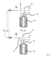
- Fig. 1 shows a schematic representation of a handset 1 for repeated local piercing of a human or animal skin.
- a handle 3 is formed outside.
- an electric motor is received as a drive in the housing 2, which can be connected via a plug device 4 to a power supply. It can be provided that also signal or control connections are realized via the plug device 4, for example for connecting the handset with an external control device (not shown) via which, for example, a speed control for the electric motor can be provided.
- the lancing module 6 can be replaced.
- the pricking module 6 one or more needles are accommodated in the usual way, which can be extended during operation by a front housing opening 7 and retracted.
- the one or more needles for their part are arranged on a needle holder (not shown) in the usual way.
- Fig. 2 shows the handset off Fig. 1 from above.
- Fig. 3 shows a perspective cross-sectional view of a portion of the handset 1.
- An electric motor 20 opposite is arranged on a drive shaft 21 designed as a driver connection or bearing member 22.
- a drive shaft 21 designed as a driver connection or bearing member 22.
- On an end face 23 of the connecting member 22 is a executed in the illustrated embodiment as a pin and obliquely Asked crank pin 24 is arranged, which in turn engages a displaceably mounted coupling member 25 in a recess 26 and this passes through in the operating position shown.
- a rotary drive movement of the drive shaft 21 is provided by means of the electric motor 20, whereby the connecting member 22 rotates, resulting in a movement of the crank pin 24 about the axial direction of the drive shaft 21.
- the connecting member 22 and the crank pin 24 as well as the coupling member 25 are part of a conversion mechanism with which the provided by the electric motor 20 via the drive shaft 21 rotational movement is converted into a linear back and forth movement of the coupling member 25.
- the crank pin 24 (not shown) via a ball joint to the coupling member 25 may be connected.
- Such a connection also causes the forward and backward movement of the coupling member 25 in the guide 27, when the crank pin 24 moves in operation about the axial direction of the drive shaft 21 due to the rotary drive movement.
- a distal end 28 of the coupling component 25 couples directly or indirectly to the needle receptacle (not shown) which carries one or more needles so that it can be repeatedly moved back and forth during operation, in particular along a straight trajectory.
- a housing cover 29 is removably disposed on the housing 2, which has an open receiving space 31 for a distal end 32 of the crank pin on an inner side 30. In the receiving space 31, the distal end 32 moves in operation. It may be provided that the crank pin 24 is detachably received on the connecting member 22, for example, inserted or screwed. This makes it possible in particular to replace the crank pin 24, either because of wear or for inserting a crank pin with a different design, for example, to provide a changed inclination of the crank pin 24 to the axial direction of the drive shaft.
- damping means may be arranged, for example, particles with spherical shape, in particular tungsten particles, with which vibrations occurring in operation are damped (shock absorption).
- the housing cover 29 may be made in one piece or, as shown, in several pieces.
- a sleeve 34 is rotatably received on the housing 2.
- the sleeve 34 By rotating the sleeve 34, which is coupled to a thread (not shown), for example, to the component 35, the sleeve 34 is displaced in the axial direction of the drive shaft 21, in particular continuously, so that by means of relative displacement in the axial direction of the drive shaft 21 of Distance of the sleeve 34 to the recess 26 changed.
- the electric motor 20 and the connection or bearing component 22 coupling thereto are entrained, which finally changes the position of the recess 26 along the oblique crank pin 24. In the exemplary embodiment shown, this means that the distance of the foot-side mounting of the crank pin 24 to the recess 26 is changed.
- the setting of the stroke can be performed in this or other versions during operation of the drive device, so if the drive shaft 21 rotates.
- the described stroke adjustment by means of displacement of the coupling location (tapping or tapping point for drive movement) along the oblique crank pin 24 can also be used in hand-held devices which differ with respect to other constructive features of the embodiment shown.
- the connecting component 22 can be displaced in the axial direction on the drive shaft 21, whereby the relative position of the crank pin 24 to the recess 26 can be changed for stroke adjustment.
- a provided on the housing 2 component (not shown) allow actuation of the displacement from the outside, as explained above for the sleeve 34.
- crank pin 24 comparable to a cone shell, performs a rotational movement about the drive shaft 21.
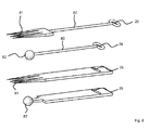
- Fig. 4 a schematic representation of a drive device with crank pin 24 in different rotational positions with a stroke h 1 , wherein in the region of a tap (40) a ball joint decoupling 41 (ball joint bearing unit) is provided
- the representations A and B show different rotational positions for the ball pin 24.
- a change of Distance d of the coupling between crank pin 24 and coupling member 25 changes the stroke h, which in Fig. 5 for a reduced stroke h 2 - at an increased distance d 2 > d 1 - is shown (h 2 ⁇ h 1 ).
- Fig. 5 show the two representations C and D again different rotational positions for the ball pin 24 (end points of the lifting movement).
- Fig. 6 and 7 show comparable to the Fig. 4 and 5 different rotational positions for the ball pin 24, which couples to the running as a flat connecting rod coupling member 25.
- Fig. 8 shows various representations of coupling components for coupling to the crank pin 24.
- the recess 26 is formed in a wire bracket 80, whereas in the lower embodiments in Fig. 8 a slot is provided as a recess 26.
- Two of the designs in Fig. 8 see a lancing device 81, whereas in the other two embodiments, a coupling element 82 is formed.
Abstract
Die Anmeldung betrifft ein Antriebsmodul für ein Handgerät zum wiederholten lokalen Aufstechen einer menschlichen oder tierischen Haut mit einem Modulgehäuse, einer Antriebseinrichtung, einem Wandlungsmechanismus, und einer Kopplungseinrichtung, wobei der Wandlungsmechanismus einen mit der Antriebswelle (21) funktionell verbundenes und zur axialen Richtung der Antriebswelle (21) schräg gestellten Kurbelzapfen (24) aufweist, welcher infolge der rotierenden Antriebsbewegung in eine Bewegung um eine zur axialen Richtung der Antriebswelle (21) parallele Achse versetzt wird, und wobei der Kurbelzapfen (24) an ein quer zur axialen Richtung der Antriebswelle (21) hin und her verlagerbares und an ein mit der Nadelaufnahme des Stechmoduls koppelbares Kopplungsbauteil (25) koppelt, derart, dass im Betrieb die Bewegung des Kurbelzapfens (24) im Bereich eines Abgriffs in eine Vor- und Zurückbewegung des Kopplungsbauteils (25) quer zur axialen Richtung der Antriebswelle (21) gewandelt wird. Es ist eine Hubeinstellvorrichtung vorgesehen, mit der ein Hub der Vor- und Zurückbewegung der Nadelaufnahme quer zur axialen Richtung der Antriebswelle (21) einstellbar ist. Weiterhin betrifft die Anmeldung ein Handgerät sowie ein Verfahren zum Betreiben eines Handgeräts.The application relates to a drive module for a handheld device for repeated local piercing of a human or animal skin with a module housing, a drive device, a conversion mechanism, and a coupling device, wherein the conversion mechanism operatively connected to the drive shaft (21) and to the axial direction of the drive shaft ( 21) inclined crank pin (24), which is due to the rotational drive movement in a movement about an axial direction of the drive shaft (21) parallel axis offset, and wherein the crank pin (24) to a transverse to the axial direction of the drive shaft (21 ) and displaceable to a coupled with the needle receiving the lancing module coupling member (25) coupled such that in operation, the movement of the crank pin (24) in the region of a tap in a forward and backward movement of the coupling member (25) transversely to the axial Direction of the drive shaft (21) is converted. There is provided a Hubeinstellvorrichtung, with which a stroke of the forward and backward movement of the needle receiving transversely to the axial direction of the drive shaft (21) is adjustable. Furthermore, the application relates to a hand-held device and a method for operating a hand-held device.
Description
Die Erfindung betrifft ein Antriebsmodul für ein Handgerät zum wiederholten Aufstechen einer menschlichen oder tierischen Haut, ein Handgerät sowie Verfahren.The invention relates to a drive module for a hand-held device for repeatedly piercing a human or animal skin, a hand-held device and methods.
Vorrichtungen zum lokalen Aufstechen einer menschlichen oder einer tierischen Haut werden in der Regel als Handgeräte ausgeführt. Vom Bedienpersonal können derartige Handgeräte zum Aufbringen einer Farbe für eine Tätowierung (Tattoo) und / oder permanentes Make-up im Bereich der Hautoberfläche verwendet werden. Aber auch das Einbringen kosmetischer oder medizinischer Wirkstoffe über die Haut ist mit solchen Geräten möglich, indem die haut lokal aufgestochen wird. Darüber hinaus können solche Geräte verwendet werden, ohne dass irgendeine Substanz eingebracht wird, zum Beispiel zur Hautstimulierung.Devices for local piercing of a human or an animal skin are usually carried out as handsets. Operators may use such hand-held devices to apply a tattoo paint and / or permanent make-up around the skin surface. But also the introduction of cosmetic or medical agents through the skin is possible with such devices by the skin is locally pierced. In addition, such devices can be used without introducing any substance, for example for skin stimulation.
Ein Handgerät zum lokalen Aufstechen einer Haut ist beispielsweise aus der Druckschrift
Aus dem Dokument
Das Dokument
Das Dokument
Das Dokument
Eine weitere Tätowiervorrichtung ist in dem Dokument
Aufgabe der Erfindung ist es, ein Antriebsmodul für ein Handgerät zum wiederholten lokalen Aufstechen einer menschlichen oder tierischen Haut sowie ein Handgerät anzugeben, bei denen im Betrieb des Handgerätes der Bedienkomfort verbessert ist, insbesondere hinsichtlich störender Begleiterscheinungen, wie zum Beispiel Geräusche oder Vibrationen des Handgeräts.The object of the invention is to provide a drive module for a hand-held device for repeated local piercing of a human or animal skin and a handheld device in which the ease of use is improved during operation of the handset, in particular with regard to disturbing side effects, such as noise or vibration of the handset.
Zur Lösung der Aufgabe ist ein Antriebsmodul für ein Handgerät zum wiederholten lokalen Aufstechen einer menschlichen oder tierischen Haut nach dem unabhängigen Anspruch 1 geschaffen. Weiter betrifft der unabhängige Anspruch 12 ein Handgerät. Weiterhin ist ein Verfahren zum Betreiben eines Handgeräts zum wiederholten lokalen Aufstechen einer menschlichen oder tierischen Haut nach dem unabhängigen Anspruch 14 geschaffen. Vorteilhafte Ausgestaltungen sind Gegenstand von abhängigen Unteransprüchen.To solve the problem, a drive module for a hand-held device for repeated local piercing of a human or animal skin is provided according to
Ein Handgerät zum wiederholten lokalen Aufstechen einer menschlichen oder tierischen Haut weist ein Gehäuse mit einem hieran gebildeten Handgriff auf. Im Betrieb des Handgerätes, welches im Fall der Nutzung zum Ausbilden Tattoos oder permanentem Make-up auch als Tätowiervorrichtung bezeichnet werden kann, greift der Nutzer den Handgriff, um das Handgerät zu führen. Andere Anwendungen sehen das lokale Aufstechen der Haut zum Einbringen eines kosmetischen oder eines medizinischen Wirkstoffes vor. Aber auch für das lokale Aufstechen der menschlichen oder tierischen Haut ohne Einbringen irgendeiner Substanz kann das Handgerät genutzt werden, zum Beispiel zur Hautstimulierung. Im Gehäuse ist eine Antriebseinrichtung aufgenommen, mit der über eine Antriebswelle eine rotierende Antriebskraft bereitgestellt wird. Hierfür kann ein Elektromotor vorgesehen sein.A hand-held device for repeated local piercing of a human or animal skin has a housing with a handle formed thereon. During operation of the hand-held device, which in the case of use for forming tattoos or permanent make-up can also be referred to as tattooing device, the user grips the handle to guide the hand-held device. Other applications include local piercing of the skin for the introduction of a cosmetic or a medicinal agent. But even for the local piercing of human or animal skin without introducing any substance, the handset can be used, for example for skin stimulation. In the housing, a drive device is received, with which via a drive shaft, a rotating drive force is provided. For this purpose, an electric motor can be provided.
An die Antriebswelle koppelt ein Wandlungsmechanismus, der im Gehäuse angeordnet und eingerichtet ist, die rotierende Antriebsbewegung in eine nicht rotierende Antriebsbewegung zu wandeln. Die hierdurch bereitgestellte Antriebskraft kann zum Beispiel axial ausgerichtet sein, beispielsweise parallel zur Achse der Antriebswelle. Es ist weiterhin eine Stecheinrichtung vorgesehen, die im Gehäuse aufgenommen ist und eine oder mehrere Stechnadeln aufweist, die an einer Nadelaufnahme angeordnet sind. Im Fall von mehreren Nadeln können diese in Gruppen angeordnet sein, in denen die Nadeln einander nahestehen. Aber auch die Verteilung von Nadeln oder Nadelgruppen über die Fläche einer Nadelplatte kann vorgesehen sein. In diesem Fall ist die Nadelaufnahme mit einer Nadelplatte gebildet. Die Nadelaufnahme ist verbunden mit dem Wandlungsmechanismus und wird zusammen mit der einen oder den mehreren Stechnadeln im Betrieb entlang einer Bewegungsbahn wiederholt vor und zurück bewegt, beispielweise in axialer Richtung. Die Bewegungsbahn kann aus verschieden ausgebildeten Teilabschnitten bestehen.To the drive shaft couples a conversion mechanism which is arranged in the housing and adapted to convert the rotary drive movement in a non-rotating drive movement. The driving force provided thereby can, for example, be axially aligned, for example parallel to the axis of the drive shaft. There is further provided a lancing device, which is accommodated in the housing and has one or more piercing needles, which are arranged on a needle holder. In the case of multiple needles can these may be arranged in groups in which the needles are close to each other. But also the distribution of needles or groups of needles over the surface of a needle plate can be provided. In this case, the needle holder is formed with a needle plate. The needle receptacle is connected to the conversion mechanism and, together with the one or more piercing needles, is repeatedly moved back and forth along a movement path, for example in the axial direction. The trajectory may consist of differently shaped sections.
Der Wandlungsmechanismus weist einen zur axialen Richtung der Antriebswelle schräg gestellten Kurbelzapfen auf. Der Kurbelzapfen steht mit der Antriebswelle funktionell in Verbindung, so dass er infolge der rotierenden Antriebsbewegung in eine Bewegung um die axiale Richtung der Antriebswelle versetzt wird. Der Kurbelzapfen koppelt im Bereich eines Abgriffs an ein quer zur axialen Richtung der Antriebswelle hin und her verlagerbares und mit der Nadelaufnahme in Verbindung stehendes Kopplungsbauteil, derart, dass die Bewegung des Kurbelzapfens in eine Vor- und Zurückbewegung des Kopplungsbauteils und somit der Nadelaufnahme quer zur axialen Richtung der Antriebswelle gewandelt wird. Die Vor- und Zurückbewegung des Kopplungsbauteils kann beispielsweise als eine lineare Bewegung ausgeführt werden. Im Betrieb bewegt sich hierdurch die Nadelaufnahme mit der einen oder den mehreren Stechnadeln quer zur axialen Richtung der Antriebswelle vor und zurück (repetierend), wobei Spitzen der Stechnadel wenigstens in der Endstellung der Vorwärtsbewegung außerhalb des Gehäuses angeordnet sein können.The conversion mechanism has a crank pin inclined to the axial direction of the drive shaft. The crank pin is operatively connected to the drive shaft so as to be displaced in a movement about the axial direction of the drive shaft due to the rotary drive movement. The crank pin coupled in the region of a tap to a transversely displaceable transversely to the axial direction of the drive shaft and with the needle-receiving coupling member, such that the movement of the crank pin in a back and forth movement of the coupling member and thus the needle holder transverse to the axial Direction of the drive shaft is converted. The forward and backward movement of the coupling member may be performed, for example, as a linear movement. In operation, this causes the needle holder with the one or more piercing needles to move back and forth transversely to the axial direction of the drive shaft, wherein tips of the piercing needle may be located outside the housing at least in the end position of forward movement.
Es ist eine Hubeinstellvorrichtung vorgesehen, mit der ein Hub der Vor- und Zurückbewegung der Nadelaufnahme quer zur axialen Richtung der Antriebswelle einstellbar ist. Der Hub ist die axial ausgerichtete Bewegung zwischen den Umkehrpunkten der linearen Vor- und Zurückbewegung der Nadelaufnahme oder des hieran koppelnden Kopplungsbauteils. Er beeinflusst, wie weit die Nadelspitze der einen oder der mehreren Stechnadeln im Betrieb vorwärts bewegt wird, wodurch in einer Ausgestaltung die Einstechtiefe im lokalen Bereich der aufzustechenden Haut beeinflusst werden kann. Mit Hilfe der Verstellbarkeit des Hubes der axial ausgerichteten Antriebsbewegung können das Antriebsmodul und das Handgerät für unterschiedliche Anwendungszwecke eingestellt werden.There is provided a Hubeinstellvorrichtung, with which a stroke of the forward and backward movement of the needle holder is adjustable transversely to the axial direction of the drive shaft. The stroke is the axially aligned movement between the reversal points of the linear back and forth movement of the needle receiver or the coupling component coupling thereto. It affects how far the needle tip of the one or more piercing needles is moved forward during operation, whereby in one embodiment the piercing depth in the local area of the skin to be aufzustechenden can be influenced. With the help of the adjustability of the stroke of the axially aligned drive movement, the drive module and the handset can be set for different applications.
Die Antriebseinrichtung, insbesondere ein Elektromotor, kann in einem zum Handgriff am Gehäuse querstehenden Gehäuseabschnitt aufgenommen sein. Die Antriebseinrichtung kann eingerichtet sein, im Betrieb eine drehende Antriebsbewegung von wenigstens etwa 1.800 min-1 (30 Hz) bereitzustellen.The drive device, in particular an electric motor, can be accommodated in a housing section which is transverse to the handle on the housing. The drive means may be arranged to provide a rotational driving movement of at least about 1,800 min -1 (30 Hz) during operation.
Das Gehäuse kann aus einem einzigen Material oder einer Kombination verschiedenen Materialien bestehen, wozu insbesondere Metall und Kunststoff gehören. Gehäuseabschnitte können lösbar montiert sein, um zum Beispiel Bereiche des Gehäuseinneren zu Austausch- oder Wartungszwecken freizugeben. Aus dem Gehäuse kann eine Kabelverbindung herausgeführt sein, die zum Anschluss des Handgerätes oder des Antriebsmoduls an ein externes Steuergerät dient. Die Kabelverbindung kann einerseits dem Anschließen eines Elektromotors an eine Energiequelle dienen. Andererseits kann die Kabelverbindung Datenkabel aufweisen, über die zwischen dem Handgerät oder dem Antriebsmodul und dem Steuergerät elektronische Daten austauschbar sind. Ein solcher Datenaustausch kann alternativ oder ergänzend auch über eine drahtlose Datenverbindung ausgeführt werden, zum Beispiel unter Verwendung der Bluetooth-Technologie. Steuergeräte für Handgeräte zum wiederholten lokalen Aufstechen einer menschlichen oder tierischen Haut oder Antriebsmodule sind als solche in verschiedenen Ausführungsformen bekannt und werden hier daher nicht näher erläutert.The housing may consist of a single material or a combination of different materials, including in particular metal and plastic. Housing sections may be detachably mounted to, for example, release areas of the housing interior for replacement or maintenance. From the housing, a cable connection can be led out, which serves to connect the handset or the drive module to an external control unit. On the one hand, the cable connection can serve to connect an electric motor to an energy source. On the other hand, the cable connection can have data cables, via which electronic data can be exchanged between the handheld device or the drive module and the control unit. Such data exchange can alternatively or additionally also be carried out via a wireless data connection, for example using the Bluetooth technology. Control devices for hand tools for repeated local piercing of a human or animal skin or drive modules are known as such in various embodiments and will therefore not be explained in detail here.
In den verschiedenen Ausführungsformen kann die Kopplung zwischen Wandlungsmechanismus und Nadelaufnahme, die mit einem Nadelschaft gebildet sein kann, derart ausgeführt sein, dass die Nadelaufnahme aufgrund der axial ausgerichteten Antriebskraft nicht nur vorgefahren wird, sondern auch mittels des das Kopplungsbauteil umfassenden Wandlungsmechanismus zurückgezogen wird. Bei dieser Ausführungsform stellt der Wandlungsmechanismus selbst eine Rückstellkraft bereit. Alternativ oder ergänzend kann vorgesehen sein, dass die Rückstellkraft wenigstens teilweise von einem elastischen Element bereitgestellt wird, beispielsweise einer Feder oder einer Membran. Bei dieser Ausführung erfolgt das Aus- oder Vorfahren der Nadelaufnahme mit der einen oder den mehreren Nadeln gegen eine elastische Vorspannung, die ihrerseits dann zum Zurückbewegen beiträgt oder dieses allein bewirkt. Das elastische Element zieht sich nach dem Strecken beim Ausfahren der Stechnadeln selbsttätig wieder zusammen und bewirkt so die Rückbewegung der einen oder der mehreren Nadeln. Der Kurbelzapfen kann aus einem gehärteten Material bestehen, zum Beispiel einem gehärteten Stahl.In the various embodiments, the coupling between the conversion mechanism and the needle receptacle, which may be formed with a needle shank, be designed so that the needle holder is not only driven forward due to the axially oriented driving force, but also by means of the coupling component comprising the conversion mechanism is retracted. In this embodiment, the conversion mechanism itself provides a restoring force. Alternatively or additionally, it may be provided that the restoring force is at least partially provided by an elastic element, for example a spring or a membrane. In this embodiment, the training or ancestor of the needle holder takes place with the one or more needles against a resilient bias, which in turn then contributes to moving back or this alone causes. The elastic element automatically contracts again after stretching during extension of the piercing needles and thus effects the return movement of the one or more needles. The crankpin may be made of a hardened material, for example a hardened steel.
Der Kurbelzapfen kann an einem Mitnehmerbauteil aufgenommen sein, welches an die Antriebswelle koppelt. Das Mitnehmerbauteil kann als zylindrisches Bauteil ausgeführt sein, welches lösbar oder nicht lösbar auf der Antriebswelle montiert ist. Der Kurbelzapfen kann geneigt sein zu einer Oberfläche des Mitnehmerbauteils, auf welcher der Kurbelzapfen angeordnet ist. Die Oberfläche des Mitnehmerbauteils kann im Winkel von etwa 90° zur Antriebsachse angeordnet sein. Das Mintnehmerbauteil kann als Vollmaterial- oder Hohlkörper-Bauteil ausgeführt sein. Auf einer von der Antriebseinrichtung abgewandten Stirnseite kann der Kurbelzapfen, zum Beispiel in der Ausführung als Stift, in einer zugeordneten Ausnehmung aufgenommen sein, sei es lösbar oder nicht lösbar. Das Mitnehmerbauteil kann im Gehäuse des Handgerätes von einem zugeordneten Innengehäuse wenigstens teilweise umgeben sein. Das Innengehäuse kann in einer Ausführung lösbar mit der Antriebseinrichtung verbunden sein, beispielsweise mittels einer Schraubverbindung. Das Innengehäuse kann eine Schutzhülle für das im Betrieb rotierende Mitnehmerbauteil mitbilden.The crank pin may be received on a driver component which couples to the drive shaft. The driver component may be designed as a cylindrical component which is detachably or non-detachably mounted on the drive shaft. The crankpin may be inclined to a surface of the cam member on which the crankpin is disposed. The surface of the Mitnehmerbauteils may be arranged at an angle of about 90 ° to the drive axle. The Mintnehmerbauteil can be designed as a solid material or hollow body component. On a front side remote from the drive device, the crank pin, for example in the embodiment as a pin, can be received in an associated recess, be it detachable or not detachable. The driver component may be at least partially surrounded by an associated inner housing in the housing of the handset. The inner housing can be releasably connected in one embodiment to the drive device, for example by means of a screw connection. The inner housing may form a protective cover for the rotating during operation Mitnehmerbauteil.
Der Kurbelzapfen kann, insbesondere im Bereich des Abgriffs, über ein Kugelgelenk an das Kopplungsbauteil koppeln. Das Kugelgelenk lässt einerseits die umlaufende Bewegung des Kurbelzapfens im Betrieb zu. Andererseits bewirkt es, dass aufgrund der Bewegung das Kopplungsbauteil in linearer Richtung vor- und zurückbewegt wird.The crank pin can, in particular in the region of the tap, couple via a ball joint to the coupling component. The ball joint allows on the one hand the circumferential movement of the crank pin in operation. On the other hand, it causes due to the movement, the coupling member is moved back and forth in a linear direction.
Der Kurbelzapfen kann in einem Durchbruch an dem Kopplungsbauteil freilaufend lagern, insbesondere im Bereich des Abgriffs. Der Durchbruch an dem Kopplungsbauteil, in welches der Kurbelzapfen eingreift, kann mit einer Schlitzführung gebildet sein, in welche der Kurbelzapfen frei läuft im Betrieb und die vorzugsweise quer zur axialen Richtung der Antriebswelle und zur Bewegungsrichtung des Kopplungsbauteils ausgebildet ist.The crank pin can store in an opening on the coupling component free-running, in particular in the region of the tap. The breakthrough on the coupling member into which the crank pin engages may be formed with a slot guide into which the crankpin is free to operate and which is preferably transverse to the axial direction of the drive shaft and the direction of movement of the coupling member.
Das Kopplungsbauteil kann in einer quer zur axialen Richtung der Antriebswelle ausgerichteten Führung angeordnet sein. Das Kopplungsbauteil kann abschnittsweise oder in seiner Gesamtheit in der Führung aufgenommen sein. Die Überlappung zwischen Kopplungsbauteil und zugeordneter Führung kann von der Betriebsstellung des Kurbelzapfens und des Kopplungsbauteils abhängen, wobei das Kopplungsbauteil in einer ersten Betriebsstellung vollständig und in einer zweiten Betriebsstellung nur teilweise innerhalb der Führung angeordnet ist. Die Führung für das Kopplungsbauteil kann als Schlitzführung ausgeführt sein.The coupling member may be arranged in a direction aligned transversely to the axial direction of the drive shaft guide. The coupling member may be added in sections or in its entirety in the guide. The overlap between the coupling member and associated guide may depend on the operating position of the crankpin and the coupling member depend, wherein the coupling member is arranged in a first operating position completely and in a second operating position only partially within the guide. The guide for the coupling component can be designed as a slot guide.
Mittels der Hubeinstellvorrichtung kann der Abgriff entlang des Kurbelzapfens verlagerbar sein. Allgemein kann entlang des schräggestellten Kurbelzapfens die Lage oder der Ort der Kopplung (Abgriff) zwischen dem Kurbelzapfen und dem mit der Nadelaufnahme in Verbindung stehenden Kopplungsbauteil verändert. Es ändert sich hierdurch in Richtung quer zur axialen Richtung der Antriebswelle der Abstand der der Kopplung zur Antriebswelle ändert. Der Ort der Kopplung wird zur Antriebswelle hin oder von dieser weg verlagert, wodurch der ausgeführte Hub eingestellt wird.By means of the Hubeinstellvorrichtung the tap along the crank pin can be displaced. Generally, along the tilted crankpin, the location or location of the coupling (tap) between the crankpin and the coupling member associated with the needle receiver may be changed. It thereby changes in the direction transverse to the axial direction of the drive shaft, the distance of the coupling to the drive shaft changes. The location of the coupling is displaced towards or away from the drive shaft, thereby adjusting the executed stroke.
Der Hub kann mit Hilfe der Hubeinstellvorrichtung stufenlos einstellbar sein.The stroke can be infinitely adjustable by means of Hubeinstellvorrichtung.
Es kann vorgesehen sein, dass der Hub während des laufenden Betriebs (laufende Antriebseinrichtung) verstellbar ist. Hierfür kann die Hubeinstellvorrichtung am Gehäuse einen Hubeinstellmechanismus aufweisen, mit dem es ermöglicht ist, während des laufenden Betriebs des Handgeräts, wahlweise ergänzend auch, wenn die Antriebseinrichtung nicht in Betrieb ist, den Hub zu verändern. Beispielweise kann eine Drehhülse am Gehäuse gebildet sein. Mittels Drehen der Drehhülse ist eine Hubeinstellung ermöglicht. Alternativ können zur Hubeinstellung am Gehäuse ein Verschiebebauteil und / oder ein Verstellhebel vorgesehen sein.It can be provided that the stroke during operation (current drive means) is adjustable. For this purpose, the Hubeinstellvorrichtung on the housing have a Hubeinstellmechanismus, with which it is possible, during the ongoing operation of the handset, optionally in addition, even if the drive device is not in operation to change the stroke. For example, a rotary sleeve may be formed on the housing. By turning the rotary sleeve stroke adjustment is possible. Alternatively, a displacement component and / or an adjusting lever can be provided for adjusting the stroke on the housing.
Es kann ein Verfahren zum Betreiben des Handgeräts zum wiederholten lokalen Aufstechen einer menschlichen oder tierischen Haut vorgesehen sein, bei dem mittels der Hubeinstellvorrichtung im laufenden Betrieb, also bei laufender Antriebseinrichtung (Rotation der Antriebswelle), der Hub der Vor- und Zurückbewegung der Nadelaufnahme quer zur axialen Richtung der Antriebswelle eingestellt wird.It can be provided a method for operating the handset for repeated local piercing of a human or animal skin, in which by means of Hubeinstellvorrichtung during operation, ie when the drive means (rotation of the drive shaft), the stroke of the forward and backward movement of the needle holder transversely to axial direction of the drive shaft is adjusted.
Mit Hilfe der Hubeinstellvorrichtung kann ein Abstand einer fußseitigen Lagerung des Kurbelzapfens zu dem Kopplungselement verstellbar sein. Mittels Verändern des Abstands zwischen der fußseitigen Lagerung des Kurbelzapfens, zum Beispiel an dem Mitnehmerbauteil, und dem Kopplungselement wird die Amplitude der auf das Koppelungselement eingeleiteten Bewegung verändert, wodurch sich der Hub ändert.With the help of Hubeinstellvorrichtung a distance of a foot-side mounting of the crank pin can be adjusted to the coupling element. By changing the distance between the foot-side mounting of the crank pin, for example on the driver component, and the coupling element changes the amplitude of the movement introduced onto the coupling element, whereby the stroke changes.
Alternativ oder ergänzend kann vorgesehen sein, dass der Winkel der Schrägstellung des Kurbelzapfens zur axialen Richtung der Antriebswelle veränderbar ist. Hierfür kann vorgesehen sein, Kurbelzapfen unterschiedlicher Schrägstellung zu verwenden. Alternativ kann ein schräggestellter Kurbelzapfen vorgesehen sein, welcher an dem den Kurbelzapfen aufnehmenden Bauteil mittels Drehen in unterschiedlichen Schrägstellungen verstellbar ist, wobei der Kurbelzapfen in den verschiedenen Drehstellungen einrasten kann.Alternatively or additionally, it can be provided that the angle of inclination of the crank pin is changeable to the axial direction of the drive shaft. For this purpose, it may be provided to use crank pins of different inclination. Alternatively, an inclined crank pin may be provided, which is adjustable on the component receiving the crank pin by turning in different inclinations, wherein the crank pin can engage in the various rotational positions.
Der Kurbelzapfen kann lösbar gelagert sein. Auf diese Weise kann in einer Ausgestaltung eine Austauschbarkeit des Kurbelzapfens erreicht werden. Beispielsweise kann so der Kurbelzapfen im Fall von Verschleiß oder Abnutzung ausgetauscht werden, wahlweise auch zusammen mit dem Mitnehmerbauteil, wobei letztere auch möglich ist, wenn Kurbelzapfen und Mitnehmerbauteil nicht lösbar miteinander verbunden sind. Es kann vorgesehen sein, dass der in dem Gehäuse angeordnete Kurbelzapfen über eine Gehäuseöffnung zugänglich ist, die mit einem abnehmbaren Gehäusedeckel verschlossen ist. Die Gehäuseöffnung kann zum Beispiel an einer Stirnseite, der Antriebseinrichtung gegenüberliegend, am Gehäuse gebildet sein. Der Gehäusedeckel kann mehrteilig ausgeführt sein, wobei ein Innendeckel des abnehmbaren Gehäusedeckels eine Aufnahme für einen Abschnitt des Kurbelzapfens aufweisen kann. Auch bei einer einteiligen Ausführung des Gehäusedeckels kann eine solche Aufnahme auf der Innenseite des Gehäusedeckels vorgesehen sein.The crank pin can be detachably mounted. In this way, in one embodiment, an interchangeability of the crank pin can be achieved. For example, so the crank pin can be replaced in the event of wear or tear, optionally together with the driver component, the latter is also possible if the crank pin and driver component are not detachably connected to each other. It can be provided that the crank pin arranged in the housing is accessible via a housing opening which is closed by a removable housing cover. The housing opening may be formed on the housing, for example, on an end face opposite to the drive device. The housing cover may be made in several parts, wherein an inner lid of the removable housing cover may have a receptacle for a portion of the crank pin. Even with a one-piece design of the housing cover, such a receptacle may be provided on the inside of the housing cover.
Eine Ausführungsform sieht vor, dass das Gehäuse mit mehreren Gehäusemodulen gebildet ist, wobei in einem Antriebsmodul die Antriebseinrichtung und in einem Stechmodul die Stecheinrichtung angeordnet ist. Die Gehäusemodule können lösbar oder nicht lösbar miteinander verbunden sein. In einer Ausgestaltung von lösbar miteinander verbundenen Gehäusemodulen kann das Stechmodul, welches auch als Nadelmodul bezeichnet werden kann, als sterilisiertes Einwegmodul ausgeführt sein.One embodiment provides that the housing is formed with a plurality of housing modules, wherein the drive device is arranged in a drive module and the lancing device is arranged in a lancing module. The housing modules can be detachably or non-detachably connected to each other. In an embodiment of detachably interconnected housing modules, the lancing module, which may also be referred to as a needle module, be designed as a sterilized disposable module.
Der Wandlungsmechanismus kann teilweise in dem Antriebsmodul und teilweise in dem Stechmodul gebildet sein. Hierbei kann vorgesehen sein, dass das Kopplungsbauteil in dem Stechmodul angeordnet ist, wohingegen wenigstens der Kurbelzapfen in dem Nadelmodul aufgenommen ist. Sind Antriebsmodul und Nadelmodul lösbar miteinander verbunden, kann zum Ausbilden des Wandlungsmechanismus der Kurbelzapfen beim Anbringen des Nadelmoduls an dem Antriebsmodul zum Beispiel in die zugeordnete Führung an dem Kopplungsbauteil eingesteckt werden.The conversion mechanism may be partially formed in the drive module and partially in the lancing module. It can be provided that the coupling component in the Lancing module is arranged, whereas at least the crank pin is received in the needle module. If the drive module and the needle module are releasably connected to one another, the crank pin can be plugged into the associated guide on the coupling component for attaching the needle module to the drive module, for example, to form the conversion mechanism.
An dem Gehäuse kann eine Schwingungsdämpfungseinrichtung gebildet sein. Hierzu können in einem Raum am Gehäuse stoßdämpfend wirkende Partikel angeordnet sein, zum Beispiel Kugelpartikel. Die Partikel können aus Wolfram bestehen. Die Partikel können miteinander starr oder flexibel verbunden sein. Es kann ein strömungsfähiges viskoses Medium oder ein viskoelastisches Medium die Partikel umgeben. Statt einzelner oder aller Partikel kann auch ein solitärer Körper vorgesehen sein. Der Raum kann mit einer verschließbaren Öffnung versehen sein.On the housing, a vibration damping device may be formed. For this purpose, shock-absorbing particles, for example spherical particles, can be arranged in a space on the housing. The particles can be made of tungsten. The particles can be rigidly or flexibly connected to each other. A flowable viscous medium or a viscoelastic medium may surround the particles. Instead of individual or all particles, a solitary body can also be provided. The room can be provided with a closable opening.
Es kann eine zumindest in Teilen mit dem Antrieb rotierende Einrichtung vorgesehen sein, die durch eine eigene einstellbare Massenunwucht einen Schwingungsausgleich im physikalischen Gesamtsystem herbeiführt. Es kann vorgesehen sein, die Massenunwucht der Einrichtung abhängig und / oder unabhängig von der Einstellung des Hubs zu beeinflussen, so dass das Ausmaß des Schwingungsausgleichs an die physikalischen Systemforderungen bei unterschiedlicher Hubeinstellungen anpassbar ist.It can be provided at least partially rotating with the drive means which brings about its own adjustable mass imbalance vibration compensation in the overall physical system. It can be provided to influence the mass imbalance of the device depending on and / or independently of the setting of the stroke, so that the extent of the vibration compensation to the physical system requirements at different stroke settings can be adjusted.
In Verbindung mit dem Antriebsmodul für ein Handgerät zum wiederholten lokalen Aufstechen einer menschlichen oder tierischen Haut gelten die im Zusammenhang mit Ausführungen des Handgerätes gemachten Erläuterungen entsprechend und umgekehrt. Die in Verbindung mit dem Antriebsmodul und / oder dem Handgerät zum wiederholten lokalen Aufstechen einer menschlichen oder tierischen Haut erläuterten Ausführungen gelten entsprechend für das Verfahren zum Betreiben des Antriebsmoduls oder des Handgeräts.In conjunction with the drive module for a hand-held device for repeated local piercing of a human or animal skin, the explanations given in connection with embodiments of the hand-held device apply correspondingly and vice versa. The explanations given in connection with the drive module and / or the hand-held device for repeated local piercing of a human or animal skin apply correspondingly to the method for operating the drive module or the hand-held device.
Im Folgenden werden weitere Ausführungsbeispiele unter Bezugnahme auf Figuren einer Zeichnung näher erläutert. Hierbei zeigen:
- Fig. 1
- eine schematische Darstellung eines Handgerätes zum wiederholten lokalen Aufstechen einer menschlichen oder tierischen Haut von der Seite,
- Fig. 2
- eine schematische Darstellung des Handgerätes aus
Fig. 1 von oben, - Fig. 3
- eine perspektivische Querschnittsdarstellung eines Abschnittes des Handgerätes aus
Fig. 1 , - Fig. 4
- eine schematische Darstellung einer Antriebseinrichtung mit Kurbelzapfen in verschiedenen Drehstellungen mit einem Hub h1, wobei eine Kugelgelenkentkopplung vorgesehen ist,
- Fig. 5
- eine schematische Darstellung der Antriebseinrichtung mit Kurbelzapfen aus
Fig. 4 in verschiedenen Drehstellungen mit einem Hub h2 < h1, - Fig. 6
- eine schematische Darstellung einer Antriebseinrichtung mit Kurbelzapfen in verschiedenen Drehstellungen mit einem Hub h1, wobei keine Kugelgelenkentkopplung vorgesehen ist,
- Fig. 7
- eine schematische Darstellung der Antriebseinrichtung mit Kurbelzapfen aus
Fig. 6 in verschiedenen Drehstellungen mit einem Hub h2 < h1, und - Fig. 8
- schematische Darstellungen von Kopplungsbauteilen zum Koppeln an einen schräg stehenden Kurbelzapfen.
- Fig. 1
- a schematic representation of a hand-held device for repeated local piercing of a human or animal skin from the side,
- Fig. 2
- a schematic representation of the handset
Fig. 1 from above, - Fig. 3
- a perspective cross-sectional view of a portion of the handset
Fig. 1 . - Fig. 4
- a schematic representation of a drive device with crank pin in different rotational positions with a stroke h 1 , wherein a ball joint decoupling is provided,
- Fig. 5
- a schematic representation of the drive device with crank pin
Fig. 4 in different rotational positions with a stroke h 2 <h 1 , - Fig. 6
- a schematic representation of a drive device with crank pin in different rotational positions with a stroke h 1 , wherein no ball joint decoupling is provided,
- Fig. 7
- a schematic representation of the drive device with crank pin
Fig. 6 in different rotational positions with a stroke h 2 <h 1 , and - Fig. 8
- schematic representations of coupling components for coupling to an inclined crank pin.
Es sind ein Antriebsmodul 5 sowie ein Stech- oder Nadelmodul 6 vorgesehen. Das Stechmodul 6 kann ausgetauscht werden. Im Stechmodul 6 sind in üblicher Weise ein oder mehrere Nadeln aufgenommen, die im Betrieb durch eine vordere Gehäuseöffnung 7 aus- und eingefahren werden können. Die eine oder die mehreren Nadeln ihrerseits sind an einer Nadelaufnahme (nicht dargestellt) in üblicher Weise angeordnet.There are a
Im Betrieb wird mit Hilfe des Elektromotors 20 eine rotierende Antriebsbewegung der Antriebswelle 21 bereitgestellt, wodurch sich das Verbindungsbauteil 22 dreht, was eine Bewegung des Kurbelzapfens 24 um die axiale Richtung der Antriebswelle 21 zur Folge hat.In operation, a rotary drive movement of the
Das Verbindungsbauteil 22 und der Kurbelzapfen 24 wie auch das Kopplungsbauteil 25 sind Bestandteil eines Wandlungsmechanismus, mit dem die von dem Elektromotor 20 über die Antriebswelle 21 bereitgestellte Drehbewegung in eine lineare Vor- und Zurückbewegung des Kopplungsbauteils 25 gewandelt wird. Das Kopplungsbauteil 25, bei dem die Ausnehmung 26 im proximalen Bereich angeordnet ist, bewegt sich im Betrieb in einer Führung 27, die hier flach und schlitzförmig ausgeführt ist. Alternativ zur Aufnahme des Kurbelzapfens 24 in der Ausnehmung 26 kann der Kurbelzapfen 24 über ein Kugelgelenk (nicht dargestellt) mit dem Kopplungsbauteil 25 verbunden sein. Eine solche Verbindung bewirkt ebenfalls das Vorund Zurückbewegen des Kopplungsbauteils 25 in der Führung 27, wenn sich der Kurbelzapfen 24 infolge der drehenden Antriebsbewegung im Betrieb um die axiale Richtung der Antriebswelle 21 bewegt. Es kann eine Kugelgelenk-Lagereinheit vorgesehen sein, die mehrere Funktionen wie Drehung, Gleiten, Taumeln bzw. Kreiseln an dieser Stelle realisiert.The connecting
Ein distales Ende 28 des Kopplungsbauteils 25 koppelt direkt oder indirekt an die eine oder mehrere Nadeln tragende Nadelaufnahme (nicht dargestellt), so dass diese im Betrieb repetierend vor- und zurückbewegt werden kann, insbesondere entlang einer geraden Bewegungsbahn.A
Bei der dargestellten Ausführungsform in
In einem Raum 33 im Gehäusedeckel 29 können Dämpfungsmittel angeordnet sein, zum Beispiel Partikel mit Kugelform, insbesondere Wolframpartikel, mit denen im Betrieb auftretende Schwingungen gedämpft werden (Stoßabsorption). Der Gehäusedeckel 29 kann einstückig oder, wie gezeigt, mehrstückig ausgeführt sein.In a space 33 in the housing cover 29 damping means may be arranged, for example, particles with spherical shape, in particular tungsten particles, with which vibrations occurring in operation are damped (shock absorption). The housing cover 29 may be made in one piece or, as shown, in several pieces.
Eine Hülse 34 ist drehbar am Gehäuse 2 aufgenommen. Mittels Drehen der Hülse 34, die an ein Gewinde (nicht dargestellt) koppelt, zum Beispiel zum Bauteil 35 hin, wird die Hülse 34 in axialer Richtung der Antriebswelle 21 verlagert, insbesondere stufenlos, so dass sich mittels Relativverlagerung in axialer Richtung der Antriebswelle 21 der Abstand der Hülse 34 zur Ausnehmung 26 verändert. Hierbei werden der Elektromotor 20 sowie das hieran koppelnde Verbindungs- oder Lagerbauteil 22 mitgenommen, was schließlich die Lage der Ausnehmung 26 entlang des schrägen Kurbelzapfens 24 ändert. Im gezeigten Ausführungsbeispiel bedeutet dies, dass sich der Abstand der fußseitigen Lagerung des Kurbelzapfens 24 zur Ausnehmung 26 verändert wird. Auf diese Weise wird die Relativposition der Ausnehmung 26, wo der Abgriff der Antriebsbewegung erfolgt, entlang des schräg gestellten Kurbelzapfens 24 geändert, was quer zur axialen Richtung der Antriebswelle 21 den Abstand der Ausnehmung 26 (Abgriff) zur Antriebswelle 21 ändert und so zur Hubverstellung führt.A
Das Einstellen des Hubs kann bei dieser oder anderen Ausführungen auch im laufenden Betrieb der Antriebseinrichtung ausgeführt werden, wenn sich also die Antriebswelle 21 dreht. Die beschriebene Hubeinstellung mittels Verlagern des Kopplungsorts (Abgriff oder Abgreifpunkt für Antriebsbewegung) entlang des schrägen Kurbelzapfens 24 kann auch bei Handgeräten zum Einsatz kommen, die sich hinsichtlich anderer konstruktiver Merkmale von dem gezeigten Ausführungsbeispiel unterscheiden.The setting of the stroke can be performed in this or other versions during operation of the drive device, so if the
So kann zum Beispiel alternativ oder ergänzend vorgesehen sein, dass das Verbindungsbauteil 22 in axialer Richtung auf der Antriebswelle 21 verlagerbar ist, wodurch zur Hubeinstellung die Relativlage des Kurbelzapfens 24 zur Ausnehmung 26 veränderbar ist. In diesem Zusammenhang kann ein am Gehäuse 2 vorgesehenes Bauteil (nicht dargestellt) eine Betätigung der Verlagerung von außen ermöglichen, wie dies oben auch für die Hülse 34 erläutert ist.Thus, for example, alternatively or additionally, it can be provided that the connecting
Anders ausgedrückt führt der Kurbelzapfen 24, vergleichbar einer Kegelschale, eine Rotationsbewegung um die Antriebswelle 21 aus. Eine Veränderung des Abstands zwischen Rotations- und Abtriebsebene, welche weitestgehend parallel zur Rotationsebene liegt, bewirkt einen mehr oder weniger großen Kreis vom schräg gestellten Kurbelzapfen in der Abtriebsebene um die Antriebswelle 21. Mittels besonderer Abgreifmöglichkeiten (Kopplung), zum Beispiel einem Ausgleich a) des Schrägungs- oder Anstellwinkels und b) der Kurbelzapfenrotation je Umlauf und / oder c) Realisierung der Gleitfähigkeit des Abgriffs auf dem schrägen Kurbelzapfen 24 weitestgehend senkrecht zur Rotationsebene, wird eine Hubeinstellung realisiert, die im laufenden Betrieb und auch unabhängig von der Drehzahl vorgenommen werden kann.In other words, the
Es besteht hierbei die Möglichkeit, die sich auf den Nadelherausstand auswirkende verfahrensbedingte Verlagerung beider Totpunkte (Endpunkte) der abgegriffenen Linearbewegung bei der Veränderung des Hubs derart auszugleichen, dass der vordere Totpunkt (= größter Nadelherausstand) sich nicht ändert, was für den Anwender des Handgeräts sehr vorteilhaft ist.There is the possibility here of compensating the process-related displacement of both dead centers (end points) of the tapped linear motion during the change of the stroke in such a way that the front dead center (= largest needle escape) does not change, which is very important for the user of the handheld device is advantageous.
Die
Die in der vorstehenden Beschreibung, den Ansprüchen sowie der Zeichnung offenbarten Merkmale können sowohl einzeln als auch in beliebiger Kombination für die Verwirklichung der verschiedenen Ausführungen von Bedeutung sein.The features disclosed in the above description, the claims and the drawings may be important both individually and in any combination for the realization of the various embodiments.
Claims (14)
wobei der Wandlungsmechanismus einen mit der Antriebswelle (21) funktionell verbundenes und zur axialen Richtung der Antriebswelle (21) schräg gestellten Kurbelzapfen (24) aufweist, welcher infolge der rotierenden Antriebsbewegung in eine Bewegung um eine zur axialen Richtung der Antriebswelle (21) parallele Achse versetzt wird, und wobei der Kurbelzapfen (24) im Bereich eines Abgriffs (40) an ein quer zur axialen Richtung der Antriebswelle (21) hin und her verlagerbares und mit der Nadelaufnahme des Stechmoduls koppelbares Kopplungsbauteil (25) koppelt, derart, dass im Betrieb die Bewegung des Kurbelzapfens (24) in eine Vor- und Zurückbewegung des Kopplungsbauteils (25) quer zur axialen Richtung der Antriebswelle (21) gewandelt wird, gekennzeichnet durch eine Hubeinstellvorrichtung, mit der ein Hub der Vor- und Zurückbewegung der Nadelaufnahme quer zur axialen Richtung der Antriebswelle (21) einstellbar ist.
wherein the conversion mechanism comprises a crank pin (24) operatively connected to the drive shaft (21) and inclined to the axial direction of the drive shaft (21), which causes movement about an axis parallel to the axial direction of the drive shaft (21) due to the rotary drive motion is coupled, and wherein the crank pin (24) in the region of a tap (40) to a transverse to the axial direction of the drive shaft (21) back and forth and coupled to the needle receiving the lancing coupling member (25) coupled such that in operation Movement of the crank pin (24) in a back and forth movement of the coupling member (25) transversely to the axial direction of the drive shaft (21) is converted, characterized by a Hubeinstellvorrichtung, with a stroke of the forward and backward movement of the needle holder transversely to the axial direction of Drive shaft (21) is adjustable.
gekennzeichnet durch eine Hubeinstellvorrichtung, mit der ein Hub der Vor- und Zurückbewegung der Nadelaufnahme quer zur axialen Richtung der Antriebswelle (21) einstellbar ist.
characterized by a Hubeinstellvorrichtung, with which a stroke of the forward and backward movement of the needle receiving transversely to the axial direction of the drive shaft (21) is adjustable.
Priority Applications (1)
| Application Number | Priority Date | Filing Date | Title |
|---|---|---|---|
| EP15171698.2A EP2954927A1 (en) | 2014-06-12 | 2015-06-11 | Drive module for a handheld device for repeated puncturing of human or animal skin, hand-held device and method |
Applications Claiming Priority (2)
| Application Number | Priority Date | Filing Date | Title |
|---|---|---|---|
| EP14172106 | 2014-06-12 | ||
| EP15171698.2A EP2954927A1 (en) | 2014-06-12 | 2015-06-11 | Drive module for a handheld device for repeated puncturing of human or animal skin, hand-held device and method |
Publications (1)
| Publication Number | Publication Date |
|---|---|
| EP2954927A1 true EP2954927A1 (en) | 2015-12-16 |
Family
ID=50942114
Family Applications (1)
| Application Number | Title | Priority Date | Filing Date |
|---|---|---|---|
| EP15171698.2A Withdrawn EP2954927A1 (en) | 2014-06-12 | 2015-06-11 | Drive module for a handheld device for repeated puncturing of human or animal skin, hand-held device and method |
Country Status (2)
| Country | Link |
|---|---|
| US (1) | US20150367118A1 (en) |
| EP (1) | EP2954927A1 (en) |
Cited By (3)
| Publication number | Priority date | Publication date | Assignee | Title |
|---|---|---|---|---|
| EP3228349A1 (en) | 2016-04-05 | 2017-10-11 | Werner Arnold | Stroke adjustment device for l-shaped microneedle device |
| USD960085S1 (en) | 2020-03-03 | 2022-08-09 | Fk Irons Inc. | Tattoo machine battery power supply |
| US11957861B2 (en) | 2020-01-28 | 2024-04-16 | Fk Irons Inc. | Pen style wireless tattoo machine, system, and kits |
Families Citing this family (8)
| Publication number | Priority date | Publication date | Assignee | Title |
|---|---|---|---|---|
| EP2954926B1 (en) * | 2014-06-12 | 2019-08-07 | MT Derm GmbH | Handheld device for the repeated puncturing of human or animal skin |
| US10449346B2 (en) | 2015-06-05 | 2019-10-22 | Painful Pleasures, Inc. | Tattooing needle assembly |
| USD842468S1 (en) * | 2015-10-26 | 2019-03-05 | Painful Pleasures, Inc. | Tattoo needle assembly |
| US11260209B2 (en) | 2016-08-24 | 2022-03-01 | Fk Irons Inc. | Pen style microneedling machine apparatus |
| US11400268B2 (en) | 2018-10-11 | 2022-08-02 | Fk Irons Inc. | Electromagnetically driven tattoo machine and system |
| USD912818S1 (en) * | 2019-03-18 | 2021-03-09 | Hawink Inc | Tattoo machine pen |
| USD901685S1 (en) * | 2019-03-18 | 2020-11-10 | Hawink Inc | Tattoo machine pen |
| USD951439S1 (en) * | 2021-01-29 | 2022-05-10 | SIRE Industries, LLC | Multi-lumen spike |
Citations (6)
| Publication number | Priority date | Publication date | Assignee | Title |
|---|---|---|---|---|
| US5279552A (en) | 1993-01-11 | 1994-01-18 | Anton Magnet | Intradermal injection device |
| DE29919199U1 (en) | 1999-10-22 | 2000-01-20 | Medium Tech Gmbh | Tattoo and / or permanent make-up paint hand tool |
| EP1495782A1 (en) | 2003-07-08 | 2005-01-12 | MediUm-TECH Medizingeräte GmbH | Tattooing and permanent make-up device |
| CN201759989U (en) | 2010-04-27 | 2011-03-16 | 刘昌鑫 | Transmission mechanism for eyebrow tattoo machine |
| US20120279330A1 (en) | 2011-05-06 | 2012-11-08 | Mei-Chi-Na Hsinyen Co., Ltd. | Transmission mechanism of eyebrow tattoo machine |
| KR20130058843A (en) | 2011-11-28 | 2013-06-05 | 이상현 | Tattooing device |
Family Cites Families (7)
| Publication number | Priority date | Publication date | Assignee | Title |
|---|---|---|---|---|
| US2567856A (en) * | 1948-09-08 | 1951-09-11 | Helen R Polk | Attachment for the spindle housings of drill presses |
| US4508106A (en) * | 1983-02-14 | 1985-04-02 | Angres Clinic, Ltd. | Microsurgical method for applying permanent eyelid liner |
| US5471102A (en) * | 1994-05-09 | 1995-11-28 | Becker; Gregory R. | Reciprocating shaft device |
| US7695486B2 (en) * | 2002-10-02 | 2010-04-13 | Linda Dixon | Intradermal color introducing needle device, and apparatus and method involving the same |
| TW580872U (en) * | 2003-01-20 | 2004-03-21 | Jen-Kuen Chen | Improved structure of transmission mechanism for eyebrow tattooing machine |
| DE502007001393D1 (en) * | 2007-02-14 | 2009-10-08 | Mt Derm Gmbh | Drive module for a device for local piercing of a human or an animal skin and hand device |
| EP2682146B1 (en) * | 2012-07-05 | 2016-08-17 | MT Derm GmbH | Handheld device for applying tattoo ink or permanent make-up and needle module with adjustable needle penetration depth |
-
2015
- 2015-06-11 EP EP15171698.2A patent/EP2954927A1/en not_active Withdrawn
- 2015-06-11 US US14/736,531 patent/US20150367118A1/en not_active Abandoned
Patent Citations (6)
| Publication number | Priority date | Publication date | Assignee | Title |
|---|---|---|---|---|
| US5279552A (en) | 1993-01-11 | 1994-01-18 | Anton Magnet | Intradermal injection device |
| DE29919199U1 (en) | 1999-10-22 | 2000-01-20 | Medium Tech Gmbh | Tattoo and / or permanent make-up paint hand tool |
| EP1495782A1 (en) | 2003-07-08 | 2005-01-12 | MediUm-TECH Medizingeräte GmbH | Tattooing and permanent make-up device |
| CN201759989U (en) | 2010-04-27 | 2011-03-16 | 刘昌鑫 | Transmission mechanism for eyebrow tattoo machine |
| US20120279330A1 (en) | 2011-05-06 | 2012-11-08 | Mei-Chi-Na Hsinyen Co., Ltd. | Transmission mechanism of eyebrow tattoo machine |
| KR20130058843A (en) | 2011-11-28 | 2013-06-05 | 이상현 | Tattooing device |
Cited By (3)
| Publication number | Priority date | Publication date | Assignee | Title |
|---|---|---|---|---|
| EP3228349A1 (en) | 2016-04-05 | 2017-10-11 | Werner Arnold | Stroke adjustment device for l-shaped microneedle device |
| US11957861B2 (en) | 2020-01-28 | 2024-04-16 | Fk Irons Inc. | Pen style wireless tattoo machine, system, and kits |
| USD960085S1 (en) | 2020-03-03 | 2022-08-09 | Fk Irons Inc. | Tattoo machine battery power supply |
Also Published As
| Publication number | Publication date |
|---|---|
| US20150367118A1 (en) | 2015-12-24 |
Similar Documents
| Publication | Publication Date | Title |
|---|---|---|
| EP2954927A1 (en) | Drive module for a handheld device for repeated puncturing of human or animal skin, hand-held device and method | |
| EP2954926B1 (en) | Handheld device for the repeated puncturing of human or animal skin | |
| EP1958659B1 (en) | Drive module for a device for local puncturing of human or animal skin and hand-held device | |
| EP1495782B1 (en) | Tattooing and permanent make-up device | |
| EP0305357B1 (en) | Dental hand piece | |
| EP2682146B1 (en) | Handheld device for applying tattoo ink or permanent make-up and needle module with adjustable needle penetration depth | |
| DE2852040C2 (en) | Device for the optional actuation of at least two tools, in particular for purposes of dentistry | |
| EP2594312B1 (en) | Device for punctuation of an organic tissue and drive module | |
| EP2462979B1 (en) | Device for repeated punctuation of skin and punctuation module | |
| DE2944391A1 (en) | ELECTRICALLY DRIVED HAND DEVICE FOR BODY CARE, ESPECIALLY TOOTHBRUSH OR MASSAGE MACHINE | |
| EP2438867B1 (en) | Medical instrument | |
| EP3363492B1 (en) | Needle module for a drive-managed device for repeated puncturing of human or animal skin and hand-held device | |
| EP2965779A1 (en) | Application module for a handheld device for repeated application of an application element to a human or an animal skin and hand-held device | |
| EP2954925A1 (en) | Handheld device for repeated puncturing of a human or animal skin and drive module | |
| EP3254584B1 (en) | Hand-held device for skin care | |
| EP4230250A1 (en) | Hand-held microneedling device for local piercing of skin and article | |
| EP3725358B1 (en) | Hand-held device and drive system and drive module for a hand-held device for local piercing of human or animal skin | |
| DE19836376A1 (en) | Pigmenting device to apply permanent make-up or similar with pigmenting color or similar to skin has housing as hand piece with electric motor, needle and mechanism converting rotary motion into back and forth needle movement | |
| DE3200711C2 (en) | ||
| EP3093041B1 (en) | Method for the automatic control of a skin puncturing device, skin puncturing device and control device | |
| EP2671610B1 (en) | Nail module with automatic frequency and amplitude matching | |
| DE102010018391A1 (en) | Hand-held massaging apparatus for sexual stimulation of human, has rod-shaped massage head whose axis is parallelly displaced along movement path during rotation of excenter around axis of rotation, where path is deviated from straight line | |
| DE10306459B4 (en) | tattoo | |
| EP3646918A1 (en) | Device for punctuation of an organic tissue and drive module | |
| DE19945334C2 (en) | Needle stick device for tattooing a skin area |
Legal Events
| Date | Code | Title | Description |
|---|---|---|---|
| PUAI | Public reference made under article 153(3) epc to a published international application that has entered the european phase |
Free format text: ORIGINAL CODE: 0009012 |
|
| AK | Designated contracting states |
Kind code of ref document: A1 Designated state(s): AL AT BE BG CH CY CZ DE DK EE ES FI FR GB GR HR HU IE IS IT LI LT LU LV MC MK MT NL NO PL PT RO RS SE SI SK SM TR |
|
| AX | Request for extension of the european patent |
Extension state: BA ME |
|
| 17P | Request for examination filed |
Effective date: 20160609 |
|
| RBV | Designated contracting states (corrected) |
Designated state(s): AL AT BE BG CH CY CZ DE DK EE ES FI FR GB GR HR HU IE IS IT LI LT LU LV MC MK MT NL NO PL PT RO RS SE SI SK SM TR |
|
| STAA | Information on the status of an ep patent application or granted ep patent |
Free format text: STATUS: THE APPLICATION HAS BEEN WITHDRAWN |
|
| 18W | Application withdrawn |
Effective date: 20180516 |