EP2954879B1 - Kniegelenkbandage - Google Patents
Kniegelenkbandage Download PDFInfo
- Publication number
- EP2954879B1 EP2954879B1 EP15166639.3A EP15166639A EP2954879B1 EP 2954879 B1 EP2954879 B1 EP 2954879B1 EP 15166639 A EP15166639 A EP 15166639A EP 2954879 B1 EP2954879 B1 EP 2954879B1
- Authority
- EP
- European Patent Office
- Prior art keywords
- knee
- joint bandage
- bandage according
- tensioning strap
- knitwear
- Prior art date
- Legal status (The legal status is an assumption and is not a legal conclusion. Google has not performed a legal analysis and makes no representation as to the accuracy of the status listed.)
- Active
Links
Images


Classifications
-
- A—HUMAN NECESSITIES
- A61—MEDICAL OR VETERINARY SCIENCE; HYGIENE
- A61F—FILTERS IMPLANTABLE INTO BLOOD VESSELS; PROSTHESES; DEVICES PROVIDING PATENCY TO, OR PREVENTING COLLAPSING OF, TUBULAR STRUCTURES OF THE BODY, e.g. STENTS; ORTHOPAEDIC, NURSING OR CONTRACEPTIVE DEVICES; FOMENTATION; TREATMENT OR PROTECTION OF EYES OR EARS; BANDAGES, DRESSINGS OR ABSORBENT PADS; FIRST-AID KITS
- A61F13/00—Bandages or dressings; Absorbent pads
- A61F13/06—Bandages or dressings; Absorbent pads specially adapted for feet or legs; Corn-pads; Corn-rings
- A61F13/061—Bandages or dressings; Absorbent pads specially adapted for feet or legs; Corn-pads; Corn-rings for knees
- A61F13/062—Openable readjustable
-
- A—HUMAN NECESSITIES
- A61—MEDICAL OR VETERINARY SCIENCE; HYGIENE
- A61F—FILTERS IMPLANTABLE INTO BLOOD VESSELS; PROSTHESES; DEVICES PROVIDING PATENCY TO, OR PREVENTING COLLAPSING OF, TUBULAR STRUCTURES OF THE BODY, e.g. STENTS; ORTHOPAEDIC, NURSING OR CONTRACEPTIVE DEVICES; FOMENTATION; TREATMENT OR PROTECTION OF EYES OR EARS; BANDAGES, DRESSINGS OR ABSORBENT PADS; FIRST-AID KITS
- A61F5/00—Orthopaedic methods or devices for non-surgical treatment of bones or joints; Nursing devices; Anti-rape devices
- A61F5/01—Orthopaedic devices, e.g. splints, casts or braces
- A61F5/0102—Orthopaedic devices, e.g. splints, casts or braces specially adapted for correcting deformities of the limbs or for supporting them; Ortheses, e.g. with articulations
- A61F5/0104—Orthopaedic devices, e.g. splints, casts or braces specially adapted for correcting deformities of the limbs or for supporting them; Ortheses, e.g. with articulations without articulation
- A61F5/0106—Orthopaedic devices, e.g. splints, casts or braces specially adapted for correcting deformities of the limbs or for supporting them; Ortheses, e.g. with articulations without articulation for the knees
- A61F5/0109—Sleeve-like structures
-
- A—HUMAN NECESSITIES
- A61—MEDICAL OR VETERINARY SCIENCE; HYGIENE
- A61F—FILTERS IMPLANTABLE INTO BLOOD VESSELS; PROSTHESES; DEVICES PROVIDING PATENCY TO, OR PREVENTING COLLAPSING OF, TUBULAR STRUCTURES OF THE BODY, e.g. STENTS; ORTHOPAEDIC, NURSING OR CONTRACEPTIVE DEVICES; FOMENTATION; TREATMENT OR PROTECTION OF EYES OR EARS; BANDAGES, DRESSINGS OR ABSORBENT PADS; FIRST-AID KITS
- A61F5/00—Orthopaedic methods or devices for non-surgical treatment of bones or joints; Nursing devices; Anti-rape devices
- A61F5/01—Orthopaedic devices, e.g. splints, casts or braces
- A61F5/30—Pressure-pads
-
- A—HUMAN NECESSITIES
- A61—MEDICAL OR VETERINARY SCIENCE; HYGIENE
- A61F—FILTERS IMPLANTABLE INTO BLOOD VESSELS; PROSTHESES; DEVICES PROVIDING PATENCY TO, OR PREVENTING COLLAPSING OF, TUBULAR STRUCTURES OF THE BODY, e.g. STENTS; ORTHOPAEDIC, NURSING OR CONTRACEPTIVE DEVICES; FOMENTATION; TREATMENT OR PROTECTION OF EYES OR EARS; BANDAGES, DRESSINGS OR ABSORBENT PADS; FIRST-AID KITS
- A61F5/00—Orthopaedic methods or devices for non-surgical treatment of bones or joints; Nursing devices; Anti-rape devices
- A61F5/01—Orthopaedic devices, e.g. splints, casts or braces
- A61F5/0102—Orthopaedic devices, e.g. splints, casts or braces specially adapted for correcting deformities of the limbs or for supporting them; Ortheses, e.g. with articulations
- A61F2005/0132—Additional features of the articulation
- A61F2005/0146—Additional features of the articulation combining rotational and sliding movements, e.g. simulating movements of a natural joint
-
- A—HUMAN NECESSITIES
- A61—MEDICAL OR VETERINARY SCIENCE; HYGIENE
- A61F—FILTERS IMPLANTABLE INTO BLOOD VESSELS; PROSTHESES; DEVICES PROVIDING PATENCY TO, OR PREVENTING COLLAPSING OF, TUBULAR STRUCTURES OF THE BODY, e.g. STENTS; ORTHOPAEDIC, NURSING OR CONTRACEPTIVE DEVICES; FOMENTATION; TREATMENT OR PROTECTION OF EYES OR EARS; BANDAGES, DRESSINGS OR ABSORBENT PADS; FIRST-AID KITS
- A61F5/00—Orthopaedic methods or devices for non-surgical treatment of bones or joints; Nursing devices; Anti-rape devices
- A61F5/01—Orthopaedic devices, e.g. splints, casts or braces
- A61F5/0102—Orthopaedic devices, e.g. splints, casts or braces specially adapted for correcting deformities of the limbs or for supporting them; Ortheses, e.g. with articulations
- A61F2005/0132—Additional features of the articulation
- A61F2005/0172—Additional features of the articulation with cushions
- A61F2005/0176—Additional features of the articulation with cushions supporting the patella
-
- A—HUMAN NECESSITIES
- A61—MEDICAL OR VETERINARY SCIENCE; HYGIENE
- A61F—FILTERS IMPLANTABLE INTO BLOOD VESSELS; PROSTHESES; DEVICES PROVIDING PATENCY TO, OR PREVENTING COLLAPSING OF, TUBULAR STRUCTURES OF THE BODY, e.g. STENTS; ORTHOPAEDIC, NURSING OR CONTRACEPTIVE DEVICES; FOMENTATION; TREATMENT OR PROTECTION OF EYES OR EARS; BANDAGES, DRESSINGS OR ABSORBENT PADS; FIRST-AID KITS
- A61F5/00—Orthopaedic methods or devices for non-surgical treatment of bones or joints; Nursing devices; Anti-rape devices
- A61F5/01—Orthopaedic devices, e.g. splints, casts or braces
- A61F5/0102—Orthopaedic devices, e.g. splints, casts or braces specially adapted for correcting deformities of the limbs or for supporting them; Ortheses, e.g. with articulations
- A61F5/0123—Orthopaedic devices, e.g. splints, casts or braces specially adapted for correcting deformities of the limbs or for supporting them; Ortheses, e.g. with articulations for the knees
Definitions
- the invention relates to a knee joint bandage, comprising a tubular, elastic knitted body with at least one pad arranged thereon and running in the support position over the patellar tendon.
- patellar tendon syndrome An often-recognized syndrome is the so-called patellar tendon syndrome.
- the patellar tendon is an essential part of the knee-joint musculoskeletal system.
- the kneecap is located between the thigh and the lower leg on the front of the knee joint. It is part of the knee joint and has an approximately triangular shape with the apex of the triangle facing the lower leg.
- the extensor muscles of the thigh are connected by a tendon at the top of the kneecap, so the triangle basis.
- the patellar tendon runs from the tip of the triangle of the kneecap to the lower leg front. Via the patellar tendon, the force of the thigh fright muscles is transmitted to the lower leg.
- the patellar tendon is a very narrow tendon that has to absorb and transmit the entire force development. Especially at higher loads, such as those given during fast running or jumping and the like, it comes to strong and sometimes slightly jerky tensile stresses of the patellar tendon. This can lead to an overload of the tendon, which manifests itself in a tendinitis.
- a tensioning belt ie a rein
- the side of the band which possibly extends over the pad, in each case to the back of the joint, that is to say into the hollow of the knee. So he either runs completely 360 ° around, or at least extends from the one patella side over the popliteal fossa to the other kneecap side.
- the tension belt is very important to produce a desired pressure, it is on the other hand hindrance, as it impedes angling of the knee, as the tension belt constrict something.
- a higher pressure arises on the knee-knee side, which is sometimes perceived as painful, so that the advantages given on the patellar tendon are in turn nullified.
- the document DE 102008029825 A1 which is regarded as the closest prior art discloses a knee joint bandage with a knitted body and arranged thereon, extending over the patellar tendon pad, wherein the front side of the knit body, a first and second tensioning strap is provided, which in each case only partially surrounds the knitted body.
- the invention is therefore based on the problem to provide a knee joint bandage, which is improved in contrast.
- the knee joint bandage according to the invention is characterized by two separate tension straps, which are arranged on mutually opposite sides of the bandage and extend only in sections around the knitted body. Both are important for adjusting pressure on the pad.
- the first strap extends directly over the pad. Depending on how firmly the tension belt is tightened, a lower or higher pressure can be exerted on the pad. However, since this first tension belt extends only in sections and on the bandage front side, when the first tension belt is tightened, the elastic fabric reacts to stretch so as to follow the pressure resulting from the tensioning of the belt on the front side.
- the second strap runs on the back of the bandage. He is arranged vertically offset to the first strap, which - as he overlaps the pad, which in turn is above the Patellasehne diametrically opposite the squat runs.
- the second tension belt is now offset in height downwards so that it preferably extends over the upper area of the calf. Now, if this second strap is also tightened, a return to the first strap is obtained.
- the elastic knit which follows the tightening of the first tensioning belt, is retracted again via the second tensioning belt.
- the knee joint area is free of a tension belt, since the second tension belt is offset in height from the first as described and is preferably located in the upper calf area.
- the second tension belt is offset in height from the first as described and is preferably located in the upper calf area.
- the first strap should preferably rotate around a maximum of 180 °. This is readily sufficient, as it should be exercised primarily by him local pressure on the pad.
- the second tension belt can likewise rotate through a maximum of 180 °, but it can also extend, depending on the configuration of the bandage, by a slightly larger or smaller angle region around the knitted body. His job is to create sufficient back pressure to set the bandage back.
- the distance between the two straps should be - at least 4 cm, preferably at least 5 cm - based on the respective longitudinal center of the respective tensioning belt. A distance of about 6 cm has been found to be particularly useful. Regardless of how concrete the distance is, the second tension belt runs below the first tensioning belt in any case, as seen in the support position.
- Each tensioning belt is preferably guided on two eyelets, wherein the respective tensioning belt is fastened with one end to an eyelet and looped with the other end through the eyelet and fastening means, in particular Spanngurt season provided clamping elements, in the desired clamping position can be fixed. Belt guided by these eyelets, the strap can easily tightened and thus the bandage are tightened.
- the eyelets are attached to corresponding, provided on the fabric body textile or plastic retaining tabs. These retaining tabs may be part of laterally applied to the knitted body applications that form longitudinal pockets, are inserted into the stabilizing rods, be, as will be discussed below.
- the patellar tendon-side pad has according to an expedient development of the invention on its side facing the inside of the knitted body on both sides bulges, between which a plurality of projections which are directed in the support position to the patellar tendon, are provided.
- the two bulges provided on the left and right serve to hold in the depressions on the tibial bone. Over this the pad can be fixed in its page orientation something.
- the central, preferably knob-like projections exert the pressure on the patellar tendon.
- a second pad arranged on the knitted body is furthermore provided, which is arranged offset in height from the first pad and positioned in its carrying position above the kneecap.
- the first and optionally the second pad, as provided, are suitably accommodated in pockets provided on the knitted body, wherein the pockets can either be partially open so that the pads are optionally removed and, if necessary, against pads which are somewhat harder or softer than the material can be exchanged. Alternatively, the pockets can be closed on all sides, so that a removal or replacement of the pads is not possible.
- the or each pocket is preferably formed by means of a surface portion attached to the knitted body, in particular in the form of a knit section.
- This surface portion is provided on the inside of the knitted body and consequently to be made of a soft material as possible, optionally from a plush knit, so that the wearing comfort is improved.
- a surface portion it is expedient to stick this, which is very easy.
- At least one, preferably two, stabilizing elements extending from the upper to the lower edge of the knitted body, in particular in the form of elongate bars, on the knitted body.
- These slightly resilient webs stabilize the elongated respectively tubular shape of the knitted body or the bandage, so that it always remains stretched in the longitudinal direction.
- These rod-shaped stabilizing elements are preferably accommodated in pockets provided on the knitted body, wherein, as already described, corresponding surface sections or planar application pieces can be applied to the knitted body on the outside. Again, these can be glued or sewn on, the pockets are preferably closed. If the pockets are open, an exchange of the stabilizing elements or a removal is possible. At these application pieces already described tabs on which the eyelets are arranged may be provided.
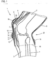
- Fig. 1 Shown is the femur 2 and the tibia 3 and the fibula 4.
- the four-headed thigh muscle 5 is connected via a tendon 6 at the patella 7, which in turn via the patellar tendon 8 with the tibia 3 is connected.
- Crossing the knee joint the knee joint bandage according to the invention is arranged.
- This knee joint bandage consists of a tubular, elastic knit body 9, on the front side of a first pocket 10 is formed, in which a pad 11 is arranged, which in the Carrying position, as in Fig. 1 shown, transversely across the patellar tendon 8 extends.
- the bag 10 is by means of an applied on the fabric inner side 12 surface portion 13, for example, also made of a knit or fabric, for. As terry. This surface portion 13 may be glued, for example.
- Above the pad 11 runs on the fabric outside a tension belt 14 which can be pulled to adjust the pressure with which the pad 11 presses on the Patellasehne 8, which will
- a second pocket 15 is further formed, in which a second pad 16 is received, which, as will be discussed below, is substantially horseshoe-shaped and the kneecap 7 engages in the support position. Also, this pocket 15 is formed by means of the surface portion 13, which extends correspondingly far up. The pad 16 serves to prevent pushing up of the kneecap 7 as a result of the pressure of the pad 11 on the patellar tendon 8.
- a second tension belt 18 is provided, the height of which is seen in the longitudinal direction of the tubular knitted body 9 below the first tensioning belt 14, that is further offset to the lower edge 19 of the knitted body 9 is positioned. It obviously runs outside the region of the popliteal fossa 20 and overlaps the calf muscle in the upper region.
- the distance between the straps - based on the respective belt center - should be z. B. be about 6 cm.
- Fig. 1 shows a sectional view
- Fig. 2 Shown is the knitted body 9 and the frontally extending tension belt 14 and the rear extending tension belt 18.
- Dashed lines show the first pad 11, which extends above the Patellasehne 8, and the second, horseshoe-shaped pad 16, the above and around the edge of the kneecap 7 is associated.
- Shown is also seen in the longitudinal direction distance d of the two straps 14 and 18. This distance d refers to the distance between the belt centers to each other.
- He should be at least 4 cm, preferably he is in Range of about 5 - 7 cm, in particular about 6 cm, each based on the geometry of the non-applied knee joint bandage. 1
- a patch surface portion 21 is further shown, which forms a running along the knitted body 9 pocket in which a dashed line shown here stabilizing element 22, preferably a spring bar, is added.
- stabilizing element 22 preferably a spring bar
- Such a pocket is also formed on the opposite side of the knitted body 9 over a corresponding surface portion, d. h., That is also provided on this page, such a stabilizing rod.
- the two rod-shaped stabilizing elements 22 serve to keep the knitted body 9 stretched in its elongated tubular shape.
- the 3 and 4 Shown is the closed first strap 14.
- the strap 14 is disposed on two eyelets 23, 24, wherein it is fixed to the strap end 25 fixed to the eyelet 23, while he 26 with his other end of the strap through the eyelet 24 is looped.
- a Velcro portion 27 is applied, while on the upper side of the tension belt 14 in the region between the eyelets 23, 24 a Velcro portion 28 is applied.
- This allows the strap end 26, starting from the open position according to FIG Fig. 4 to flip over and fix on the Velcro and Velcro sections 27, 28 in the desired, tensioned position.
- By appropriately pulling the tension belt through the eyelet 24 and turning respectively fixing in the desired length of the knitted body 9 is seen to be contracted something. Since the tensioning belt 14 extends above the first pad 11, the pressure which is exerted on the pad 11 or which is exerted via the pad 11 on the patellar tendon 8 is accordingly set by appropriate vigorous tightening.
- FIGS. 5 and 6 show the back of the knee joint bandage 1 and arranged on this side second tension belt 18.
- This tension belt 18 is guided by two eyelets 29, 30, wherein he firmly with his tensioning belt 31 at the eyelet 29 is fastened while it is looped with the other clamping strap end 32 through the eyelet 30. He also has at Spanngurtende 32 a Velcro section 33 and in the adjacent Spanngurt Scheme between the eyelets 29, 30 a Velcro section 34.
- the operation is the same as described with respect to the first tension belt 14.
- both tension straps 14 and 18 only run in the area of the respective front and rear sides of the knee joint bandage, ie they both extend by less than 180 °. If only one tension belt is present, if it is tensioned, the elastic knitted body would only be tensioned on one side, on the opposite side it would be stretched so that only insufficient pressure build-up is possible.
- a corresponding back pressure or counter-pull can consequently be produced, ie the elastic knitted body is stabilized by this and can only be stretched to a limited extent. Both straps 14 and 18 thus interact, that is, complement each other with their respective local tension effects.
- the respective eyelets 23 and 24 respectively 29 and 30 are arranged on corresponding flexible tabs 35, 36 respectively 37, 38, which in turn are fixed to the knitted body 9, but may also be part of the surface portion 21, which is to form the longitudinally running Bags serves.
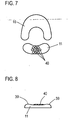
- Fig. 7 shows a plan view of the two pads 11 and 16.
- the pad 11 is slightly kidney-shaped in its basic form. She points, see Fig. 8 , two lateral bulges 39, which are directed in the support position for Patellasehne 8 and laterally next to this, so that a certain lateral stabilization respectively fixation is given against slipping sideways.
- knob-like projections 40 formed as the FIGS. 7 and 8 clearly show. These knob-like projections lie in the supporting position directly above the pad, so that on the one hand by clamping a global pressure on the pad is exercised, on the other hand on the individual, spaced-apart projections 40 and a punctual pressure.
- the second pad 16 has a horseshoe shape. It is therefore able to encompass the kneecap 7 on the top and side, ie, that the patella can be stabilized against this pad 16 against pushing away upwards.
- the two pads 11 and 16 are made of a suitable plastic material which has a certain flexibility or elasticity, for example a silicone.
Description
- Die Erfindung betrifft eine Kniegelenkbandage, umfassend einen schlauchförmigen, elastischen Gestrickkörper mit wenigstens einer daran angeordneten, in der Tragstellung über die Patellasehne verlaufenden Pelotte.
- Viele Menschen, insbesondere Sportler, klagen häufig über Knieschmerzen. Ein hierbei oft erkanntes Syndrom ist das sogenannte Patellasehnenspitzensyndrom. Die Patellasehne ist ein wesentliches Teil des knieseitigen Bewegungsapparats. Die Kniescheibe befindet sich zwischen dem Oberschenkel und dem Unterschenkel auf der Vorderseite des Kniegelenks. Sie ist Teil des Kniegelenks und weist eine in etwa dreieckige Form auf, wobei die Spitze des Dreiecks zum Unterschenkel weist. Die Streckmuskulatur des Oberschenkels ist über eine Sehne an der Oberseite der Kniescheibe, also der Dreiecksbasis angebunden. Von der Dreieckspitze der Kniescheibe läuft die Patellasehne zur Unterschenkelvorderseite. Über die Patellasehne wird die Krafteinwirkung der Oberschenkelschreckmuskulatur auf den Unterschenkel übertragen. Die Patellasehne ist eine sehr schmale Sehne, die die gesamte Kraftentwicklung aufnehmen und übertragen muss. Insbesondere bei höheren Belastungen, wie sie beim schnellen Laufen oder Springen und dergleichen gegeben sind, kommt es zu starken und mitunter leicht ruckartigen Zugbeanspruchungen der Patellasehne. Dies kann zu einer Überlastung der Sehne führen, die sich in einer Sehnenentzündung äußert.
- Zur konservativen Behandlung dieses Syndroms respektive des Schmerzes sind Kniegelenkbandagen bekannt, die aus einem schlauchförmigen, elastischen, also kompressiv wirkenden Gestrickkörper bestehen. Am Gestrickkörper ist eine Pelotte, also ein Druckkörper, angeordnet, über den gezielt Druck auf die Patellasehne ausgeübt wird. Durch diesen Druck soll der Schmerz verringert werden. Um hinreichenden Druck über die Pelotte auf die Patellasehne ausüben zu können ist bandagenseitig ein Spanngurt, also ein Zügel, vorgesehen, der, gegebenenfalls über die Pelotte verlaufend, in jedem Fall an die Rückseite des Gelenks, also in die Kniekehle geführt ist. Er läuft also entweder vollständig um 360° um, oder erstreckt sich zumindest von der einen Kniescheibenseite über die Kniekehle zur anderen Kniescheibenseite. Wenngleich der Spanngurt sehr wichtig ist, einen gewünschten Druck zu erzeugen, so ist er auf der anderen Seite hinderlich, als er ein Anwinkeln des Knies erschwert, da der Spanngurt etwas einschnürt. Durch den Spanngurt entsteht kniekehlenseitig wiederum ein höherer Druck, der mitunter als schmerzhaft empfunden wird, so dass die an der Patellasehne gegebenen Vorteile wiederum zunichte gemacht werden.
- Das Dokument
DE 102008029825 A1 , welches als nächstliegender Stand der Technik angesehen wird, offenbart eine Kniegelenkbandage mit einem Gestrickkörper und mit einer daran angeordneten, über die Patellasehne verlaufenden Pelotte, wobei am Gestrickkörper vorderseitig ein erster und zweiter Spanngurt vorgesehen ist, der jeweils nur abschnittsweise um den Gestrickkörper umläuft. - Der Erfindung liegt damit das Problem zugrunde, eine Kniegelenkbandage anzugeben, die demgegenüber verbessert ist.
- Zur Lösung dieses Problems ist eine Kniegelenkbandage gemäß Anspruch 1 vorgesehen. Weiterbildungen sind in den abhängigen Ansprüchen angegeben.
- Die erfindungsgemäße Kniegelenkbandage zeichnet sich durch zwei separate Spanngurte aus, die aneinander gegenüberliegenden Bandagenseiten angeordnet sind und sich nur abschnittsweise um den Gestrickkörper erstrecken. Beide sind zur Einstellung eines Drucks auf die Pelotte wichtig. Der erste Spanngurt erstreckt sich direkt über die Pelotte. Je nachdem, wie fest der Spanngurt angezogen wird, kann ein niedrigerer oder höherer Druck auf die Pelotte ausgeübt werden. Da sich dieser erste Spanngurt jedoch nur abschnittsweise und an der Bandagenvorderseite erstreckt, reagiert das elastische Gestrick, wenn der erste Spanngurt gestrafft wird, damit, dass es sich dehnt, um dem vorderseitig aus dem Spannen des Gurtes resultierenden Druck zu folgen.
- Der zweite Spanngurt verläuft an der Bandagenrückseite. Er ist höhenmäßigen versetzt zum ersten Spanngurt angeordnet, der - da er die Pelotte übergreift, die wiederum oberhalb der Patellasehne liegt diametral gegenüber der Kniebeuge verläuft. Der zweite Spanngurt ist nun höhenmäßig nach unten versetzt, so dass er sich bevorzugt über den oberen Bereich der Wade erstreckt. Wird nun dieser zweite Spanngurt ebenfalls gestrafft, so wird ein Gegenzug zum ersten Spanngurt erwirkt. Das elastische Gestrick, das dem Anziehen des ersten Spanngurts folgt, wird über den zweiten Spanngurt wieder zurückgezogen. Durch diese beiden Spanngurte kann folglich ein optimaler Druckaufbau erreicht werden, d. h., dass die Pelotte mit einem gewünschten Druck auf die Patellasehne gespannt werden kann. Gleichzeitig ist der Kniegelenksbereich frei von einem Spanngurt, da der zweite Spanngurt wie beschrieben höhenmäßig versetzt zum ersten verläuft und sich bevorzugt im oberen Wadenbereich befindet. Über ihn wird folglich ein Abwinkeln des Knies nicht beeinflusst, auch kommt es zu einer Druckausübung im Kniekehlenbereich, der als äußerst unangenehm empfunden werden würde.
- Der erste Spanngurt sollte bevorzugt um maximal 180° umlaufen. Dies ist ohne weiteres ausreichend, als über ihn primär lokaler Druck auf die Pelotte ausgeübt werden soll. Der zweite Spanngurt kann ebenfalls um maximal 180° umlaufen, er kann sich jedoch je nach Ausgestaltung der Bandage auch um einen etwas größeren oder kleineren Winkelbereich um den Gestrickkörper erstrecken. Seine Aufgabe ist die Erzeugung des hinreichenden Gegendrucks, um die Bandage rückseitig festzulegen.
- Der Abstand der beiden Spanngurte voneinander sollte - bezogen auf die jeweilige Längsmitte des jeweiligen Spanngurts - wenigstens 4 cm, vorzugsweise wenigstens 5 cm betragen. Ein Abstand von ca. 6 cm hat sich als besonders zweckmäßig herausgestellt. Der zweite Spanngurt verläuft, unabhängig davon, wie nun konkret der Abstand ist, in jedem Fall, gesehen in der Tragstellung, unterhalb des ersten Spanngurts.
- Jeder Spanngurt ist bevorzugt an zwei Ösen geführt, wobei der jeweilige Spanngurt mit einem Ende an einer Öse befestigt und mit dem anderen Ende durch die Öse geschlauft und über Befestigungsmittel, insbesondere spanngurtseitig vorgesehene Klemmelemente, in der gewünschten Spannposition fixierbar ist. Über diese Ösen geführte Gurt kann der Spanngurt ohne Weiteres gestrafft und damit die Bandage angezogen werden. Die Ösen sind an entsprechenden, am Gestrickkörper vorgesehenen textilen oder aus Kunststoff bestehenden Haltelaschen befestigt. Diese Haltelaschen können Teil von seitlich am Gestrickkörper aufgebrachten Applikationen, die längs laufende Taschen ausbilden, in die Stabilisierungsstäbe eingesteckt sind, sein, worauf nachfolgend noch eingegangen wird.
- Die patellasehnenseitige Pelotte weist gemäß einer zweckmäßigen Weiterbildung der Erfindung an ihrer zur Innenseite des Gestrickkörpers weisenden Seite beidseits Auswölbungen auf, zwischen denen mehrere Vorsprünge, die in der Tragstellung zur Patellasehne gerichtet sind, vorgesehen sind. Die beiden links und rechts vorgesehenen Auswölbungen dienen zum Halt in den Vertiefungen am Schienbeinkopf. Hierüber kann die Pelotte in ihrer Seitenausrichtung etwas festgelegt werden. Die mittigen, vorzugsweise noppenartigen Vorsprünge üben den Druck auf die Patellasehne aus.
- Gemäß einer besonders zweckmäßigen Weiterbildung der Erfindung ist ferner eine am Gestrickkörper angeordnete zweite Pelotte vorgesehen, die höhenmäßig versetzt zur ersten Pelotte angeordnet und in ihrer Tragstellung oberhalb der Kniescheibe positioniert ist. Wenn über die erste, der Patellasehne zugeordnete Pelotte Druck auf die Patellasehne ausgeübt wird, wird einerseits die Schmerzunterdrückung erreicht, andererseits aber wird bei höherem Druck die Kniescheibe etwas nach oben weggedrückt. Da dies mitunter als unangenehm empfunden wird respektive die Patellasehne hierüber wiederum etwas gedehnt wird, ist mit besonderem Vorteil die zweite Pelotte vorgesehen, die in der Tragstellung oberhalb der Kniescheibe positioniert ist und verhindern soll, dass die Kniescheibe nach oben weggedrückt wird. Die zweite Pelotte ist folglich der Gegenspieler zur ersten Pelotte. Bevorzugt ist die zweite Pelotte hufeisenförmig ausgeführt, so dass sie die Kniescheibe im oberen Bereich und seitlich umgreift und die Kniescheibe folglich sehr stabil in der hufeisenförmigen Pelotte aufgenommen ist.
- Die erste und gegebenenfalls die zweite Pelotte, so sie vorgesehen ist, sind zweckmäßigerweise in am Gestrickkörper vorgesehenen Taschen aufgenommen, wobei die Taschen entweder partiell offen sein können, so dass die Pelotten gegebenenfalls entnommen und bei Bedarf gegen vom Material her etwas härter oder weicher ausgelegte Pelotten ausgetauscht werden können. Alternativ können die Taschen auch allseits geschlossen sein, so dass eine Entnahme oder ein Austausch der Pelotten nicht möglich ist.
- Die oder jede Tasche ist bevorzugt mittels eines am Gestrickkörper aufgesetzten Flächenabschnitts, insbesondere in Form eines Gestrickabschnitts, gebildet. Dieser Flächenabschnitt ist an der Innenseite des Gestrickkörpers vorgesehen und folglich aus einem möglichst weichen Material zu fertigen, gegebenenfalls aus einem Plüschgestrick, damit der Tragekomfort verbessert wird. Wenngleich es möglich ist, einen Flächenabschnitt aufzunähen, ist es zweckmäßig, diesen aufzukleben, was sehr einfach möglich ist.
- Wie bereits beschrieben ist es denkbar, am Gestrickkörper wenigstens ein, vorzugsweise zwei vom oberen zum unteren Rand des Gestrickkörpers verlaufende Stabilisierungselemente, insbesondere in Form von länglichen Stäben, anzuordnen. Diese leicht federnden Stege stabilisieren die längliche respektive schlauchförmige Form des Gestrickkörpers respektive der Bandage, so dass diese stets in Längsrichtung aufgespannt bleibt. Diese stabförmigen Stabilisierungselemente sind bevorzugt in am Gestrickkörper vorgesehenen Taschen aufgenommen, wobei wie bereits beschrieben hierzu entsprechende Flächenabschnitte respektive flächige Applikationsstücke auf den Gestrickkörper außenseitig aufgebracht sein können. Wiederum können diese aufgeklebt oder aufgenäht sein, wobei die Taschen bevorzugt geschlossen sind. Sind die Taschen offen, so ist ein Austausch der Stabilisierungselemente respektive eine Entnahme möglich. An diesen Applikationsstücken können die schon beschriebenen Laschen, an denen die Ösen angeordnet sind, vorgesehen sein.
- Weitere Merkmale, Vorteile und Einzelheiten der Erfindung ergeben sich aus dem im Folgenden beschriebenen Ausführungsbeispiel sowie anhand der Zeichnungen. Dabei zeigen:
- Fig. 1
- eine Ansicht eines Kniegelenks mit daran angeordneter, im Schnitt gezeigter erfindungsgemäßer Kniegelenkbandage,
- Fig. 2
- eine Seitenansicht des erfindungsgemäßen Kniegelenkbandage,
- Fig. 3
- eine Vorderseitenansicht der erfindungsgemäßen Kniegelenkbandage mit geschlossenem Spanngurt,
- Fig. 4
- die Kniegelenkbandage aus
Fig. 3 mit geöffnetem Spanngurt, - Fig. 5
- eine Rückseitenansicht der Kniegelenkbandage aus
Fig. 3 mit geschlossenem Spanngurt, - Fig. 6
- eine Ansicht der Kniegelenkbandage aus
Fig. 5 mit geöffnetem Spanngurt, - Fig. 7
- eine Aufsicht auf die beiden Pelotten 11 und 16, und
- Fig. 8
- eine Seitenansicht der Pelotte 11.
-
Fig. 1 zeigt eine Prinzipdarstellung des menschlichen Kniegelenks mit einer daran angeordneten erfindungsgemäßen Kniegelenksbandage 1. Gezeigt ist der Oberschenkelknochen 2 sowie das Schienbein 3 und das Wadenbein 4. Der vierköpfige Oberschenkelmuskel 5 ist über eine Sehne 6 an der Kniescheibe 7 angebunden, die ihrerseits über die Patellasehne 8 mit dem Schienbein 3 verbunden ist. Das Kniegelenk übergreifend ist die erfindungsgemäße Kniegelenkbandage angeordnet. Diese Kniegelenkbandage besteht aus einem schlauchförmigen, elastischen Gestrickkörper 9, an dem vorderseitig eine erste Tasche 10 ausgebildet ist, in der eine Pelotte 11 angeordnet ist, die in der Tragstellung, wie inFig. 1 gezeigt, quer oberhalb der Patellasehne 8 verläuft. Die Tasche 10 ist mittels eines auf der Gestrickinnenseite 12 aufgebrachten Flächenabschnitts 13, beispielsweise ebenfalls aus einem Gestrick oder Gewebe, z. B. Frottee, gebildet. Dieser Flächenabschnitt 13 kann beispielsweise aufgeklebt sein. Oberhalb der Pelotte 11 verläuft an der Gestrickaußenseite ein Spanngurt 14, der gezogen werden kann, um den Druck, mit dem die Pelotte 11 auf die Patellasehne 8 drückt, einzustellen, worauf nachfolgend noch eingegangen wird. - Am Gestrickkörper 9 ist ferner eine zweite Tasche 15 ausgebildet, in der eine zweite Pelotte 16 aufgenommen ist, die, worauf nachfolgend noch eingegangen wird, im Wesentlichen hufeisenförmig ist und die Kniescheibe 7 in der Tragstellung umgreift. Auch diese Tasche 15 ist mittels des Flächenabschnitts 13, der sich entsprechend weit nach oben erstreckt, gebildet. Die Pelotte 16 dient dazu, ein Hochschieben der Kniescheibe 7 resultierend aus dem Druck der Pelotte 11 auf die Patellasehne 8 zu verhindern.
- An der Rückseite des Gestrickkörpers 9 ist ein zweiter Spanngurt 18 vorgesehen, der höhenmäßig respektive gesehen in Längsrichtung des schlauchförmigen Gestrickkörpers 9 unterhalb des ersten Spanngurts 14 verläuft, also weiter zum unteren Rand 19 des Gestrickkörpers 9 versetzt positioniert ist. Es läuft ersichtlich außerhalb des Bereichs der Kniekehle 20 und übergreift den Wadenmuskel im oberen Bereich. Der Abstand der Spanngurte - bezogen auf die jeweilige Gurtmitte - sollte z. B. ca. 6 cm betragen.
- Während
Fig. 1 quasi eine Schnittansicht zeigt, zeigtFig. 2 eine Seitenansicht der angelegten erfindungsgemäßen Kniegelenkbandage 1. Gezeigt ist der Gestrickkörper 9 sowie der vorderseitig verlaufende Spanngurt 14 und der rückseitig verlaufende Spanngurt 18. Gestrichelt gezeigt ist die erste Pelotte 11, die oberhalb der Patellasehne 8 verläuft, sowie die zweite, hufeisenförmige Pelotte 16, die oberhalb und randseitig umgreifend der Kniescheibe 7 zugeordnet ist. Dargestellt ist ferner der in Längsrichtung gesehene Abstand d der beiden Spanngurte 14 und 18. Dieser Abstand d bezieht sich auf den Abstand der Gurtmitten zueinander. Er sollte wenigstens 4 cm betragen, bevorzugt liegt er im Bereich von ca. 5 - 7 cm, insbesondere bei ca. 6 cm, jeweils bezogen auf die Geometrie der nicht angelegten Kniegelenkbandage 1. - An der Außenseite des Gestrickkörpers 9 ist ferner ein aufgesetzter Flächenabschnitt 21 gezeigt, der eine längs des Gestrickkörpers 9 verlaufende Tasche ausbildet, in der ein hier gestrichelt gezeigtes stabförmiges Stabilisierungselement 22, vorzugsweise ein Federstab, aufgenommen ist. Eine solche Tasche ist auch auf der gegenüberliegenden Seite des Gestrickkörpers 9 über einen entsprechenden Flächenabschnitt ausgebildet, d. h., dass auch auf dieser Seite ein solcher Stabilisierungsstab vorgesehen ist. Die beiden stabförmigen Stabilisierungselemente 22 dienen dazu, den Gestrickkörper 9 in seiner länglichen Schlauchform aufgespannt zu halten.
- Die
Fig. 3 und 4 zeigen die Vorderansicht der erfindungsgemäßen Kniegelenkbandage 1. Gezeigt ist der geschlossene erste Spanngurt 14. Der Spanngurt 14 ist an zwei Ösen 23, 24 angeordnet, wobei er mit dem Gurtende 25 fest an der Öse 23 befestigt ist, während er mit seinem anderen Gurtende 26 durch die Öse 24 geschlauft ist. Im Bereich des Gurtendes 26 ist ein Klettabschnitt 27 aufgebracht, während auf der Oberseite des Spanngurtes 14 im Bereich zwischen den Ösen 23, 24 ein Flauschabschnitt 28 aufgebracht ist. Dies ermöglicht es, das Gurtende 26, ausgehend von der offenen Position gemäßFig. 4 , umzuschlagen und über die Klett- und Flauschabschnitte 27, 28 in der gewünschten, gespannten Position zu fixieren. Durch entsprechendes Ziehen des Spanngurtes durch die Öse 24 und Umschlagen respektive Fixieren in der gewünschten Länge wird ersichtlich der Gestrickkörper 9 etwas zusammengezogen. Da der Spanngurt 14 oberhalb der ersten Pelotte 11 verläuft, wird folglich durch entsprechendes kräftiges Anziehen der Druck, der auf die Pelotte 11 ausgeübt wird respektive der über die Pelotte 11 auf die Patellasehne 8 ausgeübt wird, entsprechend eingestellt. - Die
Fig. 5 und 6 zeigen die Rückseite der Kniegelenkbandage 1 und den auf dieser Seite angeordneten zweiten Spanngurt 18. Auch dieser Spanngurt 18 ist durch zwei Ösen 29, 30 geführt, wobei er mit seinem Spanngurtende 31 fest an der Öse 29 befestigt ist, während er mit dem anderen Spanngurtende 32 durch die Öse 30 geschlauft ist. Auch er weist am Spanngurtende 32 einen Klettabschnitt 33 und im benachbarten Spanngurtbereich zwischen den Ösen 29, 30 einen Flauschabschnitt 34 auf. Die Funktionsweise ist die gleiche wie in Bezug auf den ersten Spanngurt 14 beschreiben. D. h., dass durch entsprechend weites Durchziehen und Umschlagen des Spanngurts durch die Öse 30 und nachfolgende Fixierung der durchgezogenen Position über die Klettabschnitte 33, 34 die gewünschte Spannstellung eingestellt und fixiert werden kann. Über diesen zweiten Spanngurt 18 kann ein Gegendruck respektive Gegenzug erwirkt werden, der quasi auf der anderen Bandagenseite erzeugt wird. Denn ersichtlich laufen beide Spanngurte 14 und 18 nur im Bereich der jeweiligen Vorder- respektive Rückseite der Kniegelenkbandage ein, d. h., sie erstrecken sich beide um weniger als 180°. Ist nur ein Spanngurt vorhanden, so würde, wenn er gespannt wird, der elastische Gestrickkörper nur an einer Seite gespannt, an der gegenüberliegenden Seite würde er gedehnt werden, so dass nur ein unzureichender Druckaufbau möglich ist. Über den erfindungsgemäß an der gegenüberliegenden Seite vorgesehenen zweiten Spanngurt kann folglich ein entsprechender Gegendruck oder Gegenzug erzeugt werden, d. h., dass der elastische Gestrickkörper hierüber stabilisiert wird und nur bedingt gedehnt werden kann. Beide Spanngurte 14 und 18 interagieren folglich, d. h., das sich ihre jeweiligen, lokalen Spannwirkungen ergänzen. - Die jeweiligen Ösen 23 und 24 respektive 29 und 30 sind an entsprechenden flexiblen Laschen 35, 36 respektive 37, 38 angeordnet, die ihrerseits wiederum an dem Gestrickkörper 9 fixiert sind, gegebenenfalls aber auch Teil des Flächenabschnitts 21 sein können, der zur Bildung der längs laufenden Taschen dient.
-
Fig. 7 zeigt eine Aufsicht auf die beiden Pelotten 11 und 16. Die Pelotte 11 ist in ihrer Grundform leicht nierenförmig. Sie weist, sieheFig. 8 , zwei seitliche Aufwölbungen 39 auf, die in der Tragstellung zur Patellasehne 8 gerichtet sind und seitlich neben dieser liegen, so dass eine gewisse Seitenstabilisierung respektive Fixierung gegen ein seitliches Wegrutschen gegeben ist. Im Bereich zwischen den beiden Aufwölbungen 39 sind noppenartige Vorsprünge 40 ausgebildet, wie dieFig. 7 und 8 deutlich zeigen. Diese noppenartigen Vorsprünge liegen in der Tragstellung direkt oberhalb der Pelotte, so dass einerseits durch das Spannen ein globaler Druck auf die Pelotte ausgeübt wird, andererseits über die einzelnen, voneinander beabstandeten Vorsprünge 40 auch ein punktueller Druck. - Wie
Fig. 7 ferner zeigt, weist die zweite Pelotte 16 eine Hufeisenform auf. Sie ist deshalb in der Lage, die Kniescheibe 7 oberseitig und seitlich zu umgreifen, d. h., dass die Kniescheibe über diese Pelotte 16 gegen ein Wegdrücken nach oben stabilisiert werden kann. Die beiden Pelotten 11 und 16 sind aus einem geeigneten Kunststoffmaterial, das eine gewisse Flexibilität respektive Elastizität aufweist, beispielsweise einem Silikon.
Claims (15)
- Kniegelenkbandage, umfassend einen schlauchförmigen, elastischen Gestrickkörper (9) mit wenigstens einer daran angeordneten, in der Tragstellung über die Patellasehne verlaufende Pelotte (11), wobei am Gestrickkörper (9) vorderseitig ein erster Spanngurt (14) vorgesehen ist, der nur abschnittsweise um den Gestrickkörper (9) umläuft und sich über die Pelotte (11) erstreckt, und wobei am Gestrickkörper (9) rückseitig und höhenmäßig versetzt zum ersten Spanngurt (14) verlaufend ein zweiter Spanngurt (18) vorgesehen ist, der nur abschnittsweise um den Gestrickkörper (9) umläuft.
- Kniegelenkbandage nach Anspruch 1, dadurch gekennzeichnet, dass der unterhalb des ersten Spanngurts (14) verlaufende zweite Spanngurt (18) vom ersten Spanngurt (14) - bezogen auf die jeweilige Gurtmitte - um wenigstens 4 cm, insbesondere um wenigstens 5 cm, und vorzugsweise um 6 cm beanstandet ist.
- Kniegelenkbandage nach Anspruch 1 oder 2, dadurch gekennzeichnet, dass der erste Spanngurt (14) um maximal 180° umläuft.
- Kniegelenkbandage nach einem der vorangehenden Ansprüche, dadurch gekennzeichnet, dass jeder Spanngurt (14, 18) an zwei Ösen (23, 24, 29, 30) geführt ist, wobei der jeweilige Spanngurt (14, 18) mit einem Ende an einer Öse (23, 29) befestigt und mit dem anderen Ende durch die andere Öse (24, 30) geschlauft und über Befestigungsmittel in der Spannposition fixierbar ist.
- Kniegelenkbandage nach Anspruch 4, dadurch gekennzeichnet, dass die Befestigungsmittel spanngurtseitig vorgesehene Klettelemente (27, 28, 33, 34) sind.
- Kniegelenkbandage nach einem der vorangehenden Ansprüche, dadurch gekennzeichnet, dass die Pelotte (11) an ihrer zur Innenseite des Gestrickkörpers (9) weisenden Seite beidseits Auswölbungen (39) aufweist, zwischen denen mehrere Vorsprünge (40), die in der Tragstellung zur Patellasehne gerichtet sind, vorgesehen sind.
- Kniegelenkbandage nach Anspruch 6, dadurch gekennzeichnet, dass die Vorsprünge (40) noppenartig sind.
- Kniegelenkbandage nach einem der vorangehenden Ansprüche, dadurch gekennzeichnet, dass eine am Gestrickkörper (9) angeordnete zweite Pelotte (16) vorgesehen ist, die höhenmäßig versetzt zur ersten Pelotte (11) angeordnet und in der Tragstellung,oberhalb der Kniescheibe positioniert ist.
- Kniegelenkbandage nach Anspruch 8, dadurch gekennzeichnet, dass die zweite Pelotte (16) hufeisenförmig ausgeführt ist.
- Kniegelenkbandage nach einem der vorangehenden Ansprüche, dadurch gekennzeichnet, dass die erste und/oder die zweite Pelotte (11, 16) in am Gestrickkörper (9) vorgesehenen Taschen (10, 15) aufgenommen sind.
- Kniegelenkbandage nach Anspruch 10, dadurch gekennzeichnet, dass die Taschen (10, 15) allseits oder nur partiell geschlossen sind.
- Kniegelenkbandage nach Anspruch 10 oder 11, dadurch gekennzeichnet, dass die oder jede Taschen (10, 15) mittels eines am Gestrickkörper (9) aufgesetzten Flächenabschnitts (13), insbesondere einem Gestrickabschnitt, gebildet ist.
- Kniegelenkbandage nach Anspruch 12, dadurch gekennzeichnet, dass der Flächenabschnitt (13) aufgeklebt ist.
- Kniegelenkbandage nach einem der vorangehenden Ansprüche, dadurch gekennzeichnet, dass am Gestrickkörper (9) wenigstens ein, vorzugsweise zwei vom oberen zum unteren Rand des Gestrickkörpers (9) verlaufende Stabilisierungselemente (22) angeordnet sind.
- Kniegelenkbandage nach Anspruch 14, dadurch gekennzeichnet, dass die stabförmigen Stabilisierungselemente (22) in am Gestrickkörper (9) vorgesehenen Taschen aufgenommen sind.
Priority Applications (1)
| Application Number | Priority Date | Filing Date | Title |
|---|---|---|---|
| PL15166639T PL2954879T3 (pl) | 2014-05-22 | 2015-05-06 | Bandaż do stawu kolanowego |
Applications Claiming Priority (1)
| Application Number | Priority Date | Filing Date | Title |
|---|---|---|---|
| DE102014107239.1A DE102014107239A1 (de) | 2014-05-22 | 2014-05-22 | Kniegelenkbandage |
Publications (2)
| Publication Number | Publication Date |
|---|---|
| EP2954879A1 EP2954879A1 (de) | 2015-12-16 |
| EP2954879B1 true EP2954879B1 (de) | 2017-07-05 |
Family
ID=53054916
Family Applications (1)
| Application Number | Title | Priority Date | Filing Date |
|---|---|---|---|
| EP15166639.3A Active EP2954879B1 (de) | 2014-05-22 | 2015-05-06 | Kniegelenkbandage |
Country Status (6)
| Country | Link |
|---|---|
| US (1) | US10159589B2 (de) |
| EP (1) | EP2954879B1 (de) |
| DE (2) | DE102014107239A1 (de) |
| ES (1) | ES2637215T3 (de) |
| PL (1) | PL2954879T3 (de) |
| RU (1) | RU2621123C2 (de) |
Cited By (2)
| Publication number | Priority date | Publication date | Assignee | Title |
|---|---|---|---|---|
| DE202022001632U1 (de) | 2022-07-20 | 2022-08-10 | Medi Gmbh & Co. Kg | Patellarsehnenbandage |
| EP3854357B1 (de) * | 2020-01-24 | 2023-05-03 | Julius Zorn GmbH | Kniegelenkbandage |
Families Citing this family (8)
| Publication number | Priority date | Publication date | Assignee | Title |
|---|---|---|---|---|
| CA2919429A1 (fr) * | 2016-01-28 | 2017-07-28 | Emmanuelle Tessier | Orthese multifonctions |
| ES2954997T3 (es) | 2017-10-26 | 2023-11-28 | Medi Gmbh & Co Kg | Ayuda médica, en particular ortopédica |
| EP3811909A1 (de) * | 2019-10-24 | 2021-04-28 | medi GmbH & Co. KG | Textilteil |
| DE102020101744A1 (de) | 2020-01-24 | 2021-07-29 | Julius Zorn Gmbh | Kniegelenkbandage |
| USD970736S1 (en) * | 2020-11-04 | 2022-11-22 | Vision Quest Industries Incorporated | Orthopedic device |
| USD955590S1 (en) * | 2020-12-04 | 2022-06-21 | Vision Quest Industries Incorporated | Orthopedic device having wrap and single strap |
| USD983382S1 (en) * | 2020-12-04 | 2023-04-11 | Vision Quest Industries Incorporated | Orthopedic device having wrap and single strap |
| USD962451S1 (en) * | 2020-12-05 | 2022-08-30 | Vision Quest Industries Incorporated | Orthopedic device with multiple Q-angle adjusters |
Citations (1)
| Publication number | Priority date | Publication date | Assignee | Title |
|---|---|---|---|---|
| DE102008029825A1 (de) * | 2008-06-25 | 2009-12-31 | Medi Gmbh & Co. Kg | Kniebandage |
Family Cites Families (11)
| Publication number | Priority date | Publication date | Assignee | Title |
|---|---|---|---|---|
| DE8115670U1 (de) * | 1981-05-26 | 1981-08-13 | Hane, Günter, Dr.med., 6229 Schlangenbad | Kniebandage |
| US4986263A (en) * | 1990-04-23 | 1991-01-22 | Biomet, Inc. | Musculoskeletal knee support |
| RU2007980C1 (ru) * | 1992-04-16 | 1994-02-28 | Акционерное общество ЭЛОРГ | Наколенник |
| US5865776A (en) * | 1997-04-09 | 1999-02-02 | Ortho-Care, Inc. | Knee brace having differential flexibility posterior and anterior panels |
| DE29803103U1 (de) * | 1998-02-21 | 1998-05-07 | Hauber Ferd Gmbh | Kniebandage |
| US6080124A (en) * | 1998-02-24 | 2000-06-27 | Fla Orthopedics, Inc. | Patella strap method |
| DE20005661U1 (de) * | 2000-03-27 | 2001-08-02 | Bauerfeind Holding Gmbh | Elastische Kniegelenkbandage |
| US6551264B1 (en) * | 2000-09-22 | 2003-04-22 | Breg, Inc. | Orthosis for dynamically stabilizing the patello-femoral joint |
| US8926539B2 (en) * | 2004-03-10 | 2015-01-06 | Dean E. Cropper | Knee orthosis and orthotic method |
| DE102004040800A1 (de) * | 2004-08-23 | 2006-03-02 | Bauerfeind Ag | Mit einem Polster versehene Gelenkbandage |
| DE102011010827B4 (de) * | 2011-01-31 | 2016-09-08 | Bauerfeind Ag | Verbesserte patellapelotte und diese enthaltende kniegelenksorthese |
-
2014
- 2014-05-22 DE DE102014107239.1A patent/DE102014107239A1/de not_active Withdrawn
- 2014-05-22 DE DE202014011197.9U patent/DE202014011197U1/de active Active
-
2015
- 2015-05-06 ES ES15166639.3T patent/ES2637215T3/es active Active
- 2015-05-06 EP EP15166639.3A patent/EP2954879B1/de active Active
- 2015-05-06 PL PL15166639T patent/PL2954879T3/pl unknown
- 2015-05-18 RU RU2015118314A patent/RU2621123C2/ru active
- 2015-05-20 US US14/717,102 patent/US10159589B2/en active Active
Patent Citations (1)
| Publication number | Priority date | Publication date | Assignee | Title |
|---|---|---|---|---|
| DE102008029825A1 (de) * | 2008-06-25 | 2009-12-31 | Medi Gmbh & Co. Kg | Kniebandage |
Cited By (2)
| Publication number | Priority date | Publication date | Assignee | Title |
|---|---|---|---|---|
| EP3854357B1 (de) * | 2020-01-24 | 2023-05-03 | Julius Zorn GmbH | Kniegelenkbandage |
| DE202022001632U1 (de) | 2022-07-20 | 2022-08-10 | Medi Gmbh & Co. Kg | Patellarsehnenbandage |
Also Published As
| Publication number | Publication date |
|---|---|
| RU2621123C2 (ru) | 2017-05-31 |
| DE102014107239A1 (de) | 2015-11-26 |
| RU2015118314A (ru) | 2016-12-10 |
| PL2954879T3 (pl) | 2017-10-31 |
| EP2954879A1 (de) | 2015-12-16 |
| ES2637215T3 (es) | 2017-10-11 |
| US10159589B2 (en) | 2018-12-25 |
| US20150335457A1 (en) | 2015-11-26 |
| DE202014011197U1 (de) | 2018-07-23 |
Similar Documents
| Publication | Publication Date | Title |
|---|---|---|
| EP2954879B1 (de) | Kniegelenkbandage | |
| EP2329800B1 (de) | Kniegelenkorthese | |
| EP2303209B1 (de) | Kniebandage | |
| EP1906890B1 (de) | Sprunggelenkbandage | |
| EP2480180B1 (de) | Aus elastischem material bestehende kniegelenkbandage mit anziehhilfe | |
| EP3086746B1 (de) | Patellarsehnenbandage | |
| EP3621562B1 (de) | Fussbewegungsdämpfungsvorrichtung und schuh zum dämpfen einer fussbewegung über das sprunggelenk | |
| EP3538038B1 (de) | Spannband | |
| EP2090273B1 (de) | Bandage | |
| EP2268245B1 (de) | Orthopädisches hilfsmittel mit einbringbarem funktionselement | |
| DE102013114839A1 (de) | Stützeinrichtung zur Anhebung eines Fußes | |
| DE102012009241B4 (de) | Fußheberorthese | |
| EP3854357B1 (de) | Kniegelenkbandage | |
| DE202012103399U1 (de) | Elastische Stützbandage | |
| DE102012209814A1 (de) | Überzieher für ein Bein, Fuß und/oder Sprunggelenk nebst Herstellungsverfahren | |
| DE202020100383U1 (de) | Kniegelenkbandage | |
| DE102016110355A1 (de) | Gliedabschnitte überbrückendes elastisches Hilfsmittel | |
| EP3854358A1 (de) | Kniegelenkbandage | |
| DE202013105928U1 (de) | Stützeinrichtung zur Anhebung eines Fußes | |
| DE102015005012B3 (de) | Orthopädiemittel mit einem federnden Stabilisierungselement | |
| EP4366669A1 (de) | Bandage für das handgelenk oder das sprunggelenk | |
| DE2625514A1 (de) | Einrichtung zur verbringung wenigstens eines der beiden an den oberschenkeln befindlichen oberen gelenkkoepfe des hueftgelenkes in die natuerliche lage | |
| DE202015002296U1 (de) | Stützelement zur Unterstützung eines Kniegelenkes eines Säugetieres | |
| DE102016102642A1 (de) | Patellabandage | |
| DE202004001936U1 (de) | Orthopädische Hilfsmittel wie Kniebandagen |
Legal Events
| Date | Code | Title | Description |
|---|---|---|---|
| PUAI | Public reference made under article 153(3) epc to a published international application that has entered the european phase |
Free format text: ORIGINAL CODE: 0009012 |
|
| AK | Designated contracting states |
Kind code of ref document: A1 Designated state(s): AL AT BE BG CH CY CZ DE DK EE ES FI FR GB GR HR HU IE IS IT LI LT LU LV MC MK MT NL NO PL PT RO RS SE SI SK SM TR |
|
| AX | Request for extension of the european patent |
Extension state: BA ME |
|
| 17P | Request for examination filed |
Effective date: 20160609 |
|
| RBV | Designated contracting states (corrected) |
Designated state(s): AL AT BE BG CH CY CZ DE DK EE ES FI FR GB GR HR HU IE IS IT LI LT LU LV MC MK MT NL NO PL PT RO RS SE SI SK SM TR |
|
| GRAP | Despatch of communication of intention to grant a patent |
Free format text: ORIGINAL CODE: EPIDOSNIGR1 |
|
| INTG | Intention to grant announced |
Effective date: 20161221 |
|
| GRAS | Grant fee paid |
Free format text: ORIGINAL CODE: EPIDOSNIGR3 |
|
| GRAA | (expected) grant |
Free format text: ORIGINAL CODE: 0009210 |
|
| AK | Designated contracting states |
Kind code of ref document: B1 Designated state(s): AL AT BE BG CH CY CZ DE DK EE ES FI FR GB GR HR HU IE IS IT LI LT LU LV MC MK MT NL NO PL PT RO RS SE SI SK SM TR |
|
| REG | Reference to a national code |
Ref country code: GB Ref legal event code: FG4D Free format text: NOT ENGLISH |
|
| REG | Reference to a national code |
Ref country code: CH Ref legal event code: EP |
|
| REG | Reference to a national code |
Ref country code: AT Ref legal event code: REF Ref document number: 906059 Country of ref document: AT Kind code of ref document: T Effective date: 20170715 |
|
| REG | Reference to a national code |
Ref country code: IE Ref legal event code: FG4D Free format text: LANGUAGE OF EP DOCUMENT: GERMAN |
|
| REG | Reference to a national code |
Ref country code: DE Ref legal event code: R096 Ref document number: 502015001369 Country of ref document: DE |
|
| REG | Reference to a national code |
Ref country code: ES Ref legal event code: FG2A Ref document number: 2637215 Country of ref document: ES Kind code of ref document: T3 Effective date: 20171011 |
|
| REG | Reference to a national code |
Ref country code: NL Ref legal event code: MP Effective date: 20170705 |
|
| REG | Reference to a national code |
Ref country code: LT Ref legal event code: MG4D |
|
| PG25 | Lapsed in a contracting state [announced via postgrant information from national office to epo] |
Ref country code: SE Free format text: LAPSE BECAUSE OF FAILURE TO SUBMIT A TRANSLATION OF THE DESCRIPTION OR TO PAY THE FEE WITHIN THE PRESCRIBED TIME-LIMIT Effective date: 20170705 Ref country code: LT Free format text: LAPSE BECAUSE OF FAILURE TO SUBMIT A TRANSLATION OF THE DESCRIPTION OR TO PAY THE FEE WITHIN THE PRESCRIBED TIME-LIMIT Effective date: 20170705 Ref country code: FI Free format text: LAPSE BECAUSE OF FAILURE TO SUBMIT A TRANSLATION OF THE DESCRIPTION OR TO PAY THE FEE WITHIN THE PRESCRIBED TIME-LIMIT Effective date: 20170705 Ref country code: NL Free format text: LAPSE BECAUSE OF FAILURE TO SUBMIT A TRANSLATION OF THE DESCRIPTION OR TO PAY THE FEE WITHIN THE PRESCRIBED TIME-LIMIT Effective date: 20170705 Ref country code: HR Free format text: LAPSE BECAUSE OF FAILURE TO SUBMIT A TRANSLATION OF THE DESCRIPTION OR TO PAY THE FEE WITHIN THE PRESCRIBED TIME-LIMIT Effective date: 20170705 Ref country code: NO Free format text: LAPSE BECAUSE OF FAILURE TO SUBMIT A TRANSLATION OF THE DESCRIPTION OR TO PAY THE FEE WITHIN THE PRESCRIBED TIME-LIMIT Effective date: 20171005 |
|
| PG25 | Lapsed in a contracting state [announced via postgrant information from national office to epo] |
Ref country code: BG Free format text: LAPSE BECAUSE OF FAILURE TO SUBMIT A TRANSLATION OF THE DESCRIPTION OR TO PAY THE FEE WITHIN THE PRESCRIBED TIME-LIMIT Effective date: 20171005 Ref country code: LV Free format text: LAPSE BECAUSE OF FAILURE TO SUBMIT A TRANSLATION OF THE DESCRIPTION OR TO PAY THE FEE WITHIN THE PRESCRIBED TIME-LIMIT Effective date: 20170705 Ref country code: IS Free format text: LAPSE BECAUSE OF FAILURE TO SUBMIT A TRANSLATION OF THE DESCRIPTION OR TO PAY THE FEE WITHIN THE PRESCRIBED TIME-LIMIT Effective date: 20171105 Ref country code: GR Free format text: LAPSE BECAUSE OF FAILURE TO SUBMIT A TRANSLATION OF THE DESCRIPTION OR TO PAY THE FEE WITHIN THE PRESCRIBED TIME-LIMIT Effective date: 20171006 Ref country code: RS Free format text: LAPSE BECAUSE OF FAILURE TO SUBMIT A TRANSLATION OF THE DESCRIPTION OR TO PAY THE FEE WITHIN THE PRESCRIBED TIME-LIMIT Effective date: 20170705 |
|
| REG | Reference to a national code |
Ref country code: DE Ref legal event code: R097 Ref document number: 502015001369 Country of ref document: DE |
|
| PG25 | Lapsed in a contracting state [announced via postgrant information from national office to epo] |
Ref country code: RO Free format text: LAPSE BECAUSE OF FAILURE TO SUBMIT A TRANSLATION OF THE DESCRIPTION OR TO PAY THE FEE WITHIN THE PRESCRIBED TIME-LIMIT Effective date: 20170705 Ref country code: DK Free format text: LAPSE BECAUSE OF FAILURE TO SUBMIT A TRANSLATION OF THE DESCRIPTION OR TO PAY THE FEE WITHIN THE PRESCRIBED TIME-LIMIT Effective date: 20170705 |
|
| PLBE | No opposition filed within time limit |
Free format text: ORIGINAL CODE: 0009261 |
|
| STAA | Information on the status of an ep patent application or granted ep patent |
Free format text: STATUS: NO OPPOSITION FILED WITHIN TIME LIMIT |
|
| REG | Reference to a national code |
Ref country code: FR Ref legal event code: PLFP Year of fee payment: 4 |
|
| PG25 | Lapsed in a contracting state [announced via postgrant information from national office to epo] |
Ref country code: SK Free format text: LAPSE BECAUSE OF FAILURE TO SUBMIT A TRANSLATION OF THE DESCRIPTION OR TO PAY THE FEE WITHIN THE PRESCRIBED TIME-LIMIT Effective date: 20170705 Ref country code: EE Free format text: LAPSE BECAUSE OF FAILURE TO SUBMIT A TRANSLATION OF THE DESCRIPTION OR TO PAY THE FEE WITHIN THE PRESCRIBED TIME-LIMIT Effective date: 20170705 Ref country code: IT Free format text: LAPSE BECAUSE OF FAILURE TO SUBMIT A TRANSLATION OF THE DESCRIPTION OR TO PAY THE FEE WITHIN THE PRESCRIBED TIME-LIMIT Effective date: 20170705 Ref country code: SM Free format text: LAPSE BECAUSE OF FAILURE TO SUBMIT A TRANSLATION OF THE DESCRIPTION OR TO PAY THE FEE WITHIN THE PRESCRIBED TIME-LIMIT Effective date: 20170705 |
|
| 26N | No opposition filed |
Effective date: 20180406 |
|
| PG25 | Lapsed in a contracting state [announced via postgrant information from national office to epo] |
Ref country code: SI Free format text: LAPSE BECAUSE OF FAILURE TO SUBMIT A TRANSLATION OF THE DESCRIPTION OR TO PAY THE FEE WITHIN THE PRESCRIBED TIME-LIMIT Effective date: 20170705 |
|
| PG25 | Lapsed in a contracting state [announced via postgrant information from national office to epo] |
Ref country code: MT Free format text: LAPSE BECAUSE OF FAILURE TO SUBMIT A TRANSLATION OF THE DESCRIPTION OR TO PAY THE FEE WITHIN THE PRESCRIBED TIME-LIMIT Effective date: 20170705 |
|
| REG | Reference to a national code |
Ref country code: CH Ref legal event code: PL |
|
| REG | Reference to a national code |
Ref country code: BE Ref legal event code: MM Effective date: 20180531 |
|
| PG25 | Lapsed in a contracting state [announced via postgrant information from national office to epo] |
Ref country code: MC Free format text: LAPSE BECAUSE OF FAILURE TO SUBMIT A TRANSLATION OF THE DESCRIPTION OR TO PAY THE FEE WITHIN THE PRESCRIBED TIME-LIMIT Effective date: 20170705 |
|
| REG | Reference to a national code |
Ref country code: IE Ref legal event code: MM4A |
|
| PG25 | Lapsed in a contracting state [announced via postgrant information from national office to epo] |
Ref country code: CH Free format text: LAPSE BECAUSE OF NON-PAYMENT OF DUE FEES Effective date: 20180531 Ref country code: LI Free format text: LAPSE BECAUSE OF NON-PAYMENT OF DUE FEES Effective date: 20180531 |
|
| PG25 | Lapsed in a contracting state [announced via postgrant information from national office to epo] |
Ref country code: LU Free format text: LAPSE BECAUSE OF NON-PAYMENT OF DUE FEES Effective date: 20180506 |
|
| PG25 | Lapsed in a contracting state [announced via postgrant information from national office to epo] |
Ref country code: IE Free format text: LAPSE BECAUSE OF NON-PAYMENT OF DUE FEES Effective date: 20180506 |
|
| PG25 | Lapsed in a contracting state [announced via postgrant information from national office to epo] |
Ref country code: BE Free format text: LAPSE BECAUSE OF NON-PAYMENT OF DUE FEES Effective date: 20180531 |
|
| GBPC | Gb: european patent ceased through non-payment of renewal fee |
Effective date: 20190506 |
|
| PG25 | Lapsed in a contracting state [announced via postgrant information from national office to epo] |
Ref country code: TR Free format text: LAPSE BECAUSE OF FAILURE TO SUBMIT A TRANSLATION OF THE DESCRIPTION OR TO PAY THE FEE WITHIN THE PRESCRIBED TIME-LIMIT Effective date: 20170705 |
|
| PG25 | Lapsed in a contracting state [announced via postgrant information from national office to epo] |
Ref country code: GB Free format text: LAPSE BECAUSE OF NON-PAYMENT OF DUE FEES Effective date: 20190506 |
|
| PG25 | Lapsed in a contracting state [announced via postgrant information from national office to epo] |
Ref country code: PT Free format text: LAPSE BECAUSE OF FAILURE TO SUBMIT A TRANSLATION OF THE DESCRIPTION OR TO PAY THE FEE WITHIN THE PRESCRIBED TIME-LIMIT Effective date: 20170705 |
|
| PG25 | Lapsed in a contracting state [announced via postgrant information from national office to epo] |
Ref country code: HU Free format text: LAPSE BECAUSE OF FAILURE TO SUBMIT A TRANSLATION OF THE DESCRIPTION OR TO PAY THE FEE WITHIN THE PRESCRIBED TIME-LIMIT; INVALID AB INITIO Effective date: 20150506 Ref country code: CY Free format text: LAPSE BECAUSE OF FAILURE TO SUBMIT A TRANSLATION OF THE DESCRIPTION OR TO PAY THE FEE WITHIN THE PRESCRIBED TIME-LIMIT Effective date: 20170705 Ref country code: MK Free format text: LAPSE BECAUSE OF NON-PAYMENT OF DUE FEES Effective date: 20170705 |
|
| PG25 | Lapsed in a contracting state [announced via postgrant information from national office to epo] |
Ref country code: AL Free format text: LAPSE BECAUSE OF FAILURE TO SUBMIT A TRANSLATION OF THE DESCRIPTION OR TO PAY THE FEE WITHIN THE PRESCRIBED TIME-LIMIT Effective date: 20170705 |
|
| PGFP | Annual fee paid to national office [announced via postgrant information from national office to epo] |
Ref country code: CZ Payment date: 20200505 Year of fee payment: 6 |
|
| REG | Reference to a national code |
Ref country code: AT Ref legal event code: MM01 Ref document number: 906059 Country of ref document: AT Kind code of ref document: T Effective date: 20200506 |
|
| PG25 | Lapsed in a contracting state [announced via postgrant information from national office to epo] |
Ref country code: AT Free format text: LAPSE BECAUSE OF NON-PAYMENT OF DUE FEES Effective date: 20200506 |
|
| PG25 | Lapsed in a contracting state [announced via postgrant information from national office to epo] |
Ref country code: CZ Free format text: LAPSE BECAUSE OF NON-PAYMENT OF DUE FEES Effective date: 20210506 |
|
| P01 | Opt-out of the competence of the unified patent court (upc) registered |
Effective date: 20230427 |
|
| PGFP | Annual fee paid to national office [announced via postgrant information from national office to epo] |
Ref country code: FR Payment date: 20230526 Year of fee payment: 9 Ref country code: DE Payment date: 20230519 Year of fee payment: 9 |
|
| PGFP | Annual fee paid to national office [announced via postgrant information from national office to epo] |
Ref country code: PL Payment date: 20230502 Year of fee payment: 9 |
|
| PGFP | Annual fee paid to national office [announced via postgrant information from national office to epo] |
Ref country code: ES Payment date: 20230725 Year of fee payment: 9 |