EP2954542B1 - Bistabiler elektromagnetischer aktuator und chirurgisches instrument - Google Patents
Bistabiler elektromagnetischer aktuator und chirurgisches instrument Download PDFInfo
- Publication number
- EP2954542B1 EP2954542B1 EP14700432.9A EP14700432A EP2954542B1 EP 2954542 B1 EP2954542 B1 EP 2954542B1 EP 14700432 A EP14700432 A EP 14700432A EP 2954542 B1 EP2954542 B1 EP 2954542B1
- Authority
- EP
- European Patent Office
- Prior art keywords
- rotor
- stator
- electromagnetic actuator
- pole shoes
- actuator
- Prior art date
- Legal status (The legal status is an assumption and is not a legal conclusion. Google has not performed a legal analysis and makes no representation as to the accuracy of the status listed.)
- Active
Links
- 230000005291 magnetic effect Effects 0.000 claims description 19
- 230000005672 electromagnetic field Effects 0.000 claims description 8
- 239000003302 ferromagnetic material Substances 0.000 claims description 3
- 230000005298 paramagnetic effect Effects 0.000 claims description 3
- 239000002907 paramagnetic material Substances 0.000 claims description 3
- 230000003287 optical effect Effects 0.000 description 4
- 238000010586 diagram Methods 0.000 description 3
- 238000006073 displacement reaction Methods 0.000 description 3
- 239000000696 magnetic material Substances 0.000 description 3
- 238000000034 method Methods 0.000 description 3
- XEEYBQQBJWHFJM-UHFFFAOYSA-N Iron Chemical compound [Fe] XEEYBQQBJWHFJM-UHFFFAOYSA-N 0.000 description 2
- 230000004323 axial length Effects 0.000 description 2
- 230000004907 flux Effects 0.000 description 2
- 230000033001 locomotion Effects 0.000 description 2
- 238000010276 construction Methods 0.000 description 1
- 230000001419 dependent effect Effects 0.000 description 1
- 230000018109 developmental process Effects 0.000 description 1
- 230000002349 favourable effect Effects 0.000 description 1
- 229910052742 iron Inorganic materials 0.000 description 1
- 239000007787 solid Substances 0.000 description 1
- 230000001360 synchronised effect Effects 0.000 description 1
Images
Classifications
-
- H—ELECTRICITY
- H01—ELECTRIC ELEMENTS
- H01F—MAGNETS; INDUCTANCES; TRANSFORMERS; SELECTION OF MATERIALS FOR THEIR MAGNETIC PROPERTIES
- H01F7/00—Magnets
- H01F7/06—Electromagnets; Actuators including electromagnets
- H01F7/08—Electromagnets; Actuators including electromagnets with armatures
- H01F7/16—Rectilinearly-movable armatures
- H01F7/1607—Armatures entering the winding
- H01F7/1615—Armatures or stationary parts of magnetic circuit having permanent magnet
-
- H—ELECTRICITY
- H02—GENERATION; CONVERSION OR DISTRIBUTION OF ELECTRIC POWER
- H02K—DYNAMO-ELECTRIC MACHINES
- H02K33/00—Motors with reciprocating, oscillating or vibrating magnet, armature or coil system
- H02K33/16—Motors with reciprocating, oscillating or vibrating magnet, armature or coil system with polarised armatures moving in alternate directions by reversal or energisation of a single coil system
-
- H—ELECTRICITY
- H02—GENERATION; CONVERSION OR DISTRIBUTION OF ELECTRIC POWER
- H02K—DYNAMO-ELECTRIC MACHINES
- H02K1/00—Details of the magnetic circuit
- H02K1/06—Details of the magnetic circuit characterised by the shape, form or construction
- H02K1/12—Stationary parts of the magnetic circuit
- H02K1/17—Stator cores with permanent magnets
-
- H—ELECTRICITY
- H01—ELECTRIC ELEMENTS
- H01F—MAGNETS; INDUCTANCES; TRANSFORMERS; SELECTION OF MATERIALS FOR THEIR MAGNETIC PROPERTIES
- H01F7/00—Magnets
- H01F7/06—Electromagnets; Actuators including electromagnets
- H01F7/08—Electromagnets; Actuators including electromagnets with armatures
- H01F7/081—Magnetic constructions
- H01F2007/083—External yoke surrounding the coil bobbin, e.g. made of bent magnetic sheet
-
- H—ELECTRICITY
- H01—ELECTRIC ELEMENTS
- H01F—MAGNETS; INDUCTANCES; TRANSFORMERS; SELECTION OF MATERIALS FOR THEIR MAGNETIC PROPERTIES
- H01F7/00—Magnets
- H01F7/06—Electromagnets; Actuators including electromagnets
- H01F7/08—Electromagnets; Actuators including electromagnets with armatures
- H01F7/081—Magnetic constructions
- H01F2007/086—Structural details of the armature
-
- H—ELECTRICITY
- H01—ELECTRIC ELEMENTS
- H01F—MAGNETS; INDUCTANCES; TRANSFORMERS; SELECTION OF MATERIALS FOR THEIR MAGNETIC PROPERTIES
- H01F7/00—Magnets
- H01F7/06—Electromagnets; Actuators including electromagnets
- H01F7/08—Electromagnets; Actuators including electromagnets with armatures
- H01F7/16—Rectilinearly-movable armatures
- H01F2007/1669—Armatures actuated by current pulse, e.g. bistable actuators
Definitions
- the invention relates to a bistable electromagnetic actuator, in particular for a surgical instrument, comprising a stator arranged outside a tube and a rotor mounted longitudinally slidably in the tube, which at least partially comprises a paramagnetic and / or ferromagnetic material and reversibly between by applying an electromagnetic field a first position and a second position is displaceable, wherein the rotor in the first and / or second position abuts a stop, wherein the stator has two oppositely axially poled annular permanent magnet, a coil for generating the electromagnetic field and a yoke element with two Statorpol mortn and the rotor protrudes neither in the first position nor in the second position in the axial direction over the annular permanent magnets, as well as a surgical instrument.
- Bistable electromagnetic actuators have a rotor that can be held in a permanent magnetic field in one of two extreme positions and can be transferred by switching an electromagnetic field from one stable position to the other stable position.
- switches can be actuated.
- these small-sized actuators can be used, for example, to change a focus or a magnification of an optical system or to change a viewing direction. This is done by an optical component is moved by the actuator, wherein the optical component is in or on the rotor of the actuator.
- A1 is a linear motor for optical systems, such as endoscopes known.
- the motor has a stator with two permanent magnets, which are magnetically interconnected in the same direction poled with a return element.
- a coil is placed between the magnets.
- On the side next to each magnet is still a pole piece magnetically connected to the return element.
- the rotor of the motor comprises a yoke of soft magnetic material, which is in magnetic engagement with the permanent magnet of the stator. By energizing the coil, the rotor can be displaced out of a rest position in the longitudinal direction.
- the runner according to DE 10 2008 042 701 A1 consists of a tubular soft magnetic element, so that due to the resulting friction of the tubular rotor on the tube, a high force must be applied to move the rotor from one position to the other position. Furthermore, the linear motor is according to DE 10 2008 042 701 A1 comparatively large-scale construction.
- a generic electromagnetic actuator for a surgical or medical instrument comprising a stator and a displaceable member slidable from a first position to a second position and held in the first position by a permanent magnetic field and in the second position also by a permanent magnetic field is or is, is in DE 10 2011 006 814 A1 disclosed.
- the present invention has for its object to provide a small-sized bistable electromagnetic actuator and a surgical instrument with a corresponding bistable electromagnetic actuator available, with smaller size larger displacement forces are exerted on the rotor.
- a bistable electromagnetic actuator in particular for a surgical instrument, comprising a stator arranged outside a tube and a rotor mounted longitudinally displaceably in the tube, which at least partially has a paramagnetic and / or ferromagnetic material and is reversibly displaceable by applying an electromagnetic field between a first position and a second position, wherein the rotor in the first and / or second position abuts against a stop, wherein the stator two oppositely axially poled Annular permanent magnet, a coil for generating the electromagnetic field and a yoke element with two Statorpol decaden and the rotor extends neither in the first position in the second position in the axial direction beyond the annular permanent magnet, wherein the return element with the Statorpol marn enclosing the coil and the Statorpol fiction on Both sides of the coil between the coil and the annular permanent magnets are arranged, wherein the rotor has two rotor pole pieces, solved by an axial width of the stator arranged outside
- the object underlying the invention is achieved in that the coil current and the power loss in the coil can be kept low by the efficiency of the coil is increased.
- This is achieved by the geometry of the actuator elements.
- the geometry of the invention is based on the fact that the return element with the stator pole no longer, as in DE 10 2008 042 701 A1 shown, enclosing both the coil and the ring magnets, but only the coil, while the ring magnets are arranged outside the Statorpol note.
- axially magnetized magnetic rings are used, as no radially arranged soft iron of the return element is necessary over them.
- stator can be realized in a smaller radial space. Since the Statorpol note are arranged between the permanent magnet and the coil, there is a higher coil efficiency, since the pole pieces are directly connected to the conclusion. As a result, the axial length of the stator and thus also the axial length of the rotor can be reduced.
- the rotor itself has rotor pole pieces, it has a central radial taper, so that at its ends in each case a pole piece is formed.
- the runner touches the pipe only in the places of the pole shoes and not over the entire surface.
- the friction between the rotor and the tube in which the rotor is arranged is reduced. This increases the efficiency of the shifting, since less frictional resistance has to be overcome.
- this reduces the negative influence of, for example, dimensional errors or deflections due to the reduced fit on two small contact surfaces or support lines.
- stator pole shoes When the axial width of the stator pole shoes is smaller than an axial stroke of the actuator between the first position and the second position, large differences between the holding force and the switching force can be realized.
- the rotor with the rotor pole pieces on an overall length in the axial direction which is greater than the outer distance of the Statorpol mon in the axial direction.
- a distance of the axial center planes of the rotor pole pieces greater than a distance of the axial center planes of the stator pole pieces.
- stator pole shoes preferably have an identical axial width with one another and / or the rotor pole shoes have an equal axial width and / or the stator and / or the rotor are symmetrical about a plane of symmetry
- a symmetrical structure of the actuator according to the invention is in the axial direction Implemented so that prevail in the two end positions or in the first position and the second position, the same holding forces and the same switching forces are used to change the position of the rotor in the actuator. It is also possible for only individual ones of the geometric dimensions mentioned to be symmetrical in each case. For example, if the actuator is permanently loaded in use from one side, it may be advantageous to break the full symmetry of the actuator in the axial direction and to realize a higher holding force and / or switching force in one position than in another position.
- the rotor abuts against a stop in the first and / or second position.
- the stop is preferably arranged in each case so that the force generated by the permanent magnets on the rotor in this position pushes or pulls the rotor further in the direction of the stop against which the rotor bears.
- the rotor pole shoe arranged at the end position covers the one opposite to it Statorpolschuh in the axial direction at least partially, wherein a center plane of the arranged at the end position Läuferpolschuhs is arranged in the axial direction to the end position over a center plane of the stator pole opposite him.
- This relates to those rotor pole piece or stator pole piece, which is arranged closer to the current end position in the axial direction.
- these may be the distal pole pieces of the stator and rotor in the distal end position. These are opposite each other.
- In the proximal end position these are the proximal pole pieces of the stator and rotor. These are also opposite.
- stator pole in the axial direction wherein a center plane of the not arranged at the end position Läuferpolschuhs is arranged in the axial direction to the end position over a center plane of the stator pole opposite him.
- the endoscope for example, in the distal end position of the runner, these are the proximal pole shoes of the rotor and stator, and vice versa.
- the invention is achieved by a surgical instrument, in particular an endoscope, with a bistable electromagnetic actuator according to the invention described above. Since the Actuator can be built very small, this can also be implemented in an endoscope with a narrow endoscope shaft.
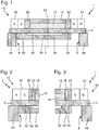
- Fig. 1 an inventive bistable electromagnetic actuator 1 is shown in cross section.
- the actuator 1 is substantially rotationally symmetrical about the central axis 4 and only one half of the actuator 1 is shown. Reflection on the central axis 4 results in the complete cut through the actuator 1.
- the actuator 1 will be described as being in a surgical instrument, namely in an endoscope having a distal end and a proximal end.
- the direction to distal is in the Fig. 1 to 3 to the left, the direction to proximal to the right, shown.
- a stator 10 Radially outside a tube 2, a stator 10 is arranged, which has two ring magnets 12, 14 which are magnetized axially in opposite directions, so that in Fig. 1 the south poles of the magnets face each other.
- the ring magnet 12 when integrated into an endoscope, the ring magnet 12 is a distal ring magnet and the ring magnet 14 is a proximal ring magnet.
- a cylindrical coil 16 is arranged symmetrically, wherein radially outside the coil 16, a likewise cylindrical return element 18 is arranged made of a soft magnetic material, which closes flush radially outward with the ring magnets 12, 14.
- the return element 18 opens distally into a distal stator pole piece 20 and proximally into a proximal stator pole piece 22.
- the return element 18 and stator pole pieces 20, 22 may be formed in one piece or from different parts, which are all magnetically soft.
- the distal ones and proximal pole pieces 20, 22 are disposed between the coil 16 and the distal and proximal ring magnets 12, 14. Overall, results in a flush radial outer end surface.
- the stator 10 according to Fig. 1 is symmetrical about a plane of symmetry 24 in the axial direction.
- the actuator 1 according to Fig. 1 has radially inside the tube 2 to a rotor 30 which, in particular, in its entirety, consists of a soft magnetic material.
- This rotor 30 is tapered in the middle and opens into a distal rotor pole piece 32 and into a proximal rotor pole piece 34, the distal rotor pole piece 32 substantially opposite the distal stator pole piece 20 and the proximal rotor pole piece 34 substantially opposite the proximal stator pole piece 22.
- the rotor 30 is tapered in the middle so that it leaves a gap 36 to the tube 2.
- the rotor 30 touches the tube 2 only with the inner surfaces of the pole shoes 32, 34, on the one hand the friction is reduced and on the other hand ensures a tilt-safe arrangement of the rotor 30 in the tube 2.
- the rotor 30 is symmetrical in the axial direction about a plane of symmetry 38.
- a distal stop 44 and a proximal stop 46 Distally and proximally of the rotor 30, its movement is limited by a distal stop 44 and a proximal stop 46.
- the stops 44, 46 are fixed in the axial direction.
- Fig. 1 a situation is shown in which the rotor 30 is held in a first position 6 by the permanent magnets 12, 14, in which the rotor 30 abuts the distal stop 45.
- the second position 8 would be that in which the rotor 30 bears against the proximal stop 46.
- FIGS. 2 and 3 are more details of the geometry of the actuator 1 off Fig. 1 shown.
- Fig. 2 It is shown that the axial width of the distal rotor pole piece 32 is greater than the axial width of the distal Statorpolschuhs 20. Also shown that in the first position 6, in which the rotor 30 abuts the distal stop 45, still a partial overlap between the distal Rotor pole piece 32 and the distal stator pole piece 20 is present. To a large extent, the distal rotor pole piece 32 in this position 6 overlaps the distal ring magnet 12.
- Fig. 2 In addition, the axial center planes 26 of the distal stator pole piece 20 and 40 of the distal rotor pole piece 32 are shown. In the first position 6 shown, the axial center plane 40 of the distal rotor pole piece 32 is arranged distally of the axial center plane 26 of the distal stator pole piece 20. Thus, since the rotor 30 with its distal rotor pole piece 32 is located closer to the distal ring magnet 12, the distal ring magnet 12 exerts a greater attractive force on the rotor pole piece 32 than the proximal ring magnet 14 does on the proximal rotor pole piece 34 of the rotor 30. Thus, the rotor 30 is held in the first position 6.
- Fig. 3 is also in the event that the rotor 30 rests in the first position 6 on the distal stop 44, a cutout in the proximal region of the actuator 1 is shown.
- the proximal rotor pole piece 34 overlaps the proximal stator pole piece 22 in its entire width.
- the middle plane 42 of the proximal rotor pole piece 34 is arranged distally of the midplane 28 of the proximal stator pole shoe 22. There is little or no overlap between the rotor 30 and the proximal ring magnet 14.
- the coil 16 is energized and the electromagnetic field generated by the coil 16 penetrates through the return element 18 and the stator pole shoes 20, 22 and through the tube 2 in the pole pieces 32, 34 of the rotor 30, in addition to the permanent magnetic fields of the ring permanent magnets 12, 14.
- This magnetic field generated by the coil 16 is in this case oriented so that it supports the magnetic field generated by the ring magnet 14 and counteracts the magnetic field generated by the ring magnet 12.
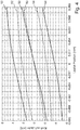
- Fig. 4 is in a force-displacement diagram, the dependence of holding forces or switching forces of the rotor position in the actuator for an actuator 1 according to the invention according to the Fig. 1 to 3 on the one hand and for a conventional actuator on the other hand, having comparable dimensions. It can be seen that the holding force 50 of the arrangement according to the invention exceeds the holding force 60 of the known arrangement by about 15%, which is clear from the fact that the slope of the curve 50 is greater than the slope of the curve 60 by about 15%.
- the solid and dashed curves 52, 54, 62 and 64 respectively show the positive and negative switching forces, ie the rotor depending on its position acting forces under positive or negative energization of the respective coil. These curves are all symmetrical with respect to a rotation through 180 ° about the origin of the coordinate system, since the underlying actuators are symmetrical.
- the curves 52 and 62 on the one hand and the curves 54 and 64 on the other hand denote the switching forces on the runners in the case of a positive switching signal or a negative switching signal.
- a significant increase in the switching forces Using the example of the curves 52 and 62 it is clear that at the rotor position -0.085 mm the jump from holding force to switching force in the actuator according to the invention over the conventional actuator, ie the difference between curves 62 and 60 on the one hand with respect to the difference between the curves
- the jump relatively means an increase of about 270%.
Landscapes
- Engineering & Computer Science (AREA)
- Power Engineering (AREA)
- Physics & Mathematics (AREA)
- Electromagnetism (AREA)
- Reciprocating, Oscillating Or Vibrating Motors (AREA)
- Instruments For Viewing The Inside Of Hollow Bodies (AREA)
- Lens Barrels (AREA)
- Endoscopes (AREA)
- Electromagnets (AREA)
Applications Claiming Priority (2)
| Application Number | Priority Date | Filing Date | Title |
|---|---|---|---|
| DE102013202019.8A DE102013202019A1 (de) | 2013-02-07 | 2013-02-07 | Bistabiler elektromagnetischer Aktuator und chirurgisches Instrument |
| PCT/EP2014/000061 WO2014121881A1 (de) | 2013-02-07 | 2014-01-14 | Bistabiler elektromagnetischer aktuator und chirurgisches instrument |
Publications (2)
| Publication Number | Publication Date |
|---|---|
| EP2954542A1 EP2954542A1 (de) | 2015-12-16 |
| EP2954542B1 true EP2954542B1 (de) | 2019-10-02 |
Family
ID=49958437
Family Applications (1)
| Application Number | Title | Priority Date | Filing Date |
|---|---|---|---|
| EP14700432.9A Active EP2954542B1 (de) | 2013-02-07 | 2014-01-14 | Bistabiler elektromagnetischer aktuator und chirurgisches instrument |
Country Status (6)
Families Citing this family (7)
| Publication number | Priority date | Publication date | Assignee | Title |
|---|---|---|---|---|
| DE102014204736A1 (de) | 2014-03-14 | 2015-09-17 | Olympus Winter & Ibe Gmbh | Bistabiler elektromagnetischer Aktuator und chirurgisches Instrument |
| JP6444765B2 (ja) * | 2015-02-24 | 2018-12-26 | オリンパス株式会社 | 撮像装置および内視鏡 |
| JP6852433B2 (ja) * | 2017-02-09 | 2021-03-31 | Tdk株式会社 | レンズ駆動装置及び電磁駆動ユニット |
| DE102017107414A1 (de) * | 2017-04-06 | 2018-10-11 | Olympus Winter & Ibe Gmbh | Stereoskopisches optisches System eines chirurgischen Instruments und Verfahren zum Herstellen desselben |
| JPWO2019026445A1 (ja) * | 2017-08-04 | 2020-04-16 | オリンパス株式会社 | 内視鏡用リニアアクチュエータ、内視鏡用光学ユニットおよび内視鏡 |
| US11344297B2 (en) * | 2019-02-28 | 2022-05-31 | Covidien Lp | Surgical stapling device with independently movable jaws |
| CN112117879B (zh) * | 2020-11-23 | 2021-02-26 | 中国科学院宁波材料技术与工程研究所 | 一种基于柔性导向的直线振动音圈电机 |
Family Cites Families (14)
| Publication number | Priority date | Publication date | Assignee | Title |
|---|---|---|---|---|
| US3103603A (en) * | 1960-11-02 | 1963-09-10 | Reutter Jean Leon | Alternating current synchronous reciprocating motor unit |
| US3119940A (en) * | 1961-05-16 | 1964-01-28 | Sperry Rand Corp | Magnetomotive actuators of the rectilinear output type |
| US4127835A (en) * | 1977-07-06 | 1978-11-28 | Dynex/Rivett Inc. | Electromechanical force motor |
| US4315197A (en) * | 1980-02-07 | 1982-02-09 | The United States Of America As Represented By The Administrator Of The National Aeronautics And Space Administration | Linear magnetic motor/generator |
| DE3538017A1 (de) * | 1985-10-25 | 1987-04-30 | Triumph Adler Ag | Elektrischer antrieb |
| DE19958888A1 (de) * | 1999-12-07 | 2001-06-13 | Sheng Chih Sheng | Magnetvorrichtung mit wechselbarem Magnetkreis und mit beiden Befestigungsstellen |
| JP2001178103A (ja) * | 1999-12-08 | 2001-06-29 | Shisei Chin | 磁石装置 |
| JP2002176758A (ja) * | 2000-09-29 | 2002-06-21 | Matsushita Electric Works Ltd | リニアオシレータ及び電動歯ブラシ |
| JP2004153907A (ja) * | 2002-10-30 | 2004-05-27 | Matsushita Electric Works Ltd | アクチュエータ |
| EP1609233B1 (de) * | 2003-03-24 | 2017-12-20 | Technische Universität Berlin | Wanderfeld-linearmotor |
| JP4027918B2 (ja) * | 2004-06-18 | 2007-12-26 | オリンパス株式会社 | 医療機器 |
| FR2929753B1 (fr) * | 2008-04-03 | 2013-09-27 | Cedrat Technologies | Actionneur magnetique controlable a fer mobile. |
| DE102008042701A1 (de) | 2008-10-09 | 2010-04-15 | How To Organize Gmbh | Linearmotor für optische Systeme |
| EP2591480B1 (de) * | 2010-07-05 | 2018-08-01 | Olympus Winter&Ibe GmbH | Elektromagnetischer aktuator für ein chirurgisches instrument |
-
2013
- 2013-02-07 DE DE102013202019.8A patent/DE102013202019A1/de not_active Ceased
-
2014
- 2014-01-14 EP EP14700432.9A patent/EP2954542B1/de active Active
- 2014-01-14 WO PCT/EP2014/000061 patent/WO2014121881A1/de active Application Filing
- 2014-01-14 JP JP2015556410A patent/JP2016509829A/ja active Pending
- 2014-01-14 CN CN201480007543.4A patent/CN104995697A/zh active Pending
-
2015
- 2015-07-31 US US14/814,733 patent/US20150340937A1/en not_active Abandoned
Non-Patent Citations (1)
| Title |
|---|
| None * |
Also Published As
| Publication number | Publication date |
|---|---|
| CN104995697A (zh) | 2015-10-21 |
| JP2016509829A (ja) | 2016-03-31 |
| DE102013202019A1 (de) | 2014-08-07 |
| US20150340937A1 (en) | 2015-11-26 |
| WO2014121881A1 (de) | 2014-08-14 |
| EP2954542A1 (de) | 2015-12-16 |
Similar Documents
| Publication | Publication Date | Title |
|---|---|---|
| EP2954542B1 (de) | Bistabiler elektromagnetischer aktuator und chirurgisches instrument | |
| EP2591480B1 (de) | Elektromagnetischer aktuator für ein chirurgisches instrument | |
| EP2362530B1 (de) | Linearmotor mit permanentmagnetischer Selbsthaltung | |
| DE102014204736A1 (de) | Bistabiler elektromagnetischer Aktuator und chirurgisches Instrument | |
| EP2178581B1 (de) | Linearantrieb und pumpsystem, insbesondere kunstherz | |
| DE102012224179A1 (de) | Elektromagnetischer Aktuator für ein chirurgisches Instrument | |
| DE102015120867A1 (de) | Elektromagnetischer Aktuator | |
| DE102009053727A1 (de) | Zykloidgetriebe | |
| DE10296891T5 (de) | Selbst-zentrierender Linear-Motor | |
| DE102015120019A1 (de) | Greifer umfassend koordiniert bewegliche Greifelemente | |
| EP3606396B1 (de) | Elektromagnetischer aktuator für ein chirurgisches instrument und verfahren zum herstellen desselben | |
| DE102012224177A1 (de) | Elektromagnetischer Aktuator für ein chirurgisches Instrument und Verfahren zum Einstellen eines Hubwegs | |
| EP1402546B1 (de) | Elektrodynamischer linearantrieb | |
| DE10247228B4 (de) | Verfahren und Vorrichtung zum Magnetisieren eines dauermagnetischen Ringmagneten mit gerader Polzahl | |
| DE10313144B3 (de) | Magnetischer Linearantrieb | |
| EP3606397B1 (de) | Stereoskopisches optisches system eines chirurgischen instruments und verfahren zum herstellen desselben | |
| DE102014206284A1 (de) | Magnetische Kupplung, Kupplungsanordnung und Verfahren | |
| EP1696541A1 (de) | Nicht rotierender Linearaktuator | |
| DE102010019318B4 (de) | Permanentmagnetretarder | |
| DE102009038324A1 (de) | Magnetische Schaltvorrichtung | |
| DE102012211513B4 (de) | Doppeltwirkender Hubmagnet mit drei stabilen Schaltstellungen | |
| DE102019101778B4 (de) | Motor, Rotor-Stator-Anordnung und Verwendung zum Betreiben eines Motors | |
| DE102018216223B3 (de) | Aktor und Verfahren zur Betätigung eines Hochspannungsschalters | |
| EP3804107A1 (de) | System und anlage mit auf einem schienenteil bewegbar angeordnetem schienenfahrzeug | |
| DE102022126607A1 (de) | Aktuator zur Erzeugung insbesondere oszillierender Antriebsbewegungen |
Legal Events
| Date | Code | Title | Description |
|---|---|---|---|
| PUAI | Public reference made under article 153(3) epc to a published international application that has entered the european phase |
Free format text: ORIGINAL CODE: 0009012 |
|
| 17P | Request for examination filed |
Effective date: 20150720 |
|
| AK | Designated contracting states |
Kind code of ref document: A1 Designated state(s): AL AT BE BG CH CY CZ DE DK EE ES FI FR GB GR HR HU IE IS IT LI LT LU LV MC MK MT NL NO PL PT RO RS SE SI SK SM TR |
|
| AX | Request for extension of the european patent |
Extension state: BA ME |
|
| DAX | Request for extension of the european patent (deleted) | ||
| GRAP | Despatch of communication of intention to grant a patent |
Free format text: ORIGINAL CODE: EPIDOSNIGR1 |
|
| STAA | Information on the status of an ep patent application or granted ep patent |
Free format text: STATUS: GRANT OF PATENT IS INTENDED |
|
| INTG | Intention to grant announced |
Effective date: 20190606 |
|
| GRAS | Grant fee paid |
Free format text: ORIGINAL CODE: EPIDOSNIGR3 |
|
| GRAA | (expected) grant |
Free format text: ORIGINAL CODE: 0009210 |
|
| STAA | Information on the status of an ep patent application or granted ep patent |
Free format text: STATUS: THE PATENT HAS BEEN GRANTED |
|
| AK | Designated contracting states |
Kind code of ref document: B1 Designated state(s): AL AT BE BG CH CY CZ DE DK EE ES FI FR GB GR HR HU IE IS IT LI LT LU LV MC MK MT NL NO PL PT RO RS SE SI SK SM TR |
|
| REG | Reference to a national code |
Ref country code: GB Ref legal event code: FG4D Free format text: NOT ENGLISH |
|
| REG | Reference to a national code |
Ref country code: AT Ref legal event code: REF Ref document number: 1187082 Country of ref document: AT Kind code of ref document: T Effective date: 20191015 Ref country code: CH Ref legal event code: EP |
|
| REG | Reference to a national code |
Ref country code: DE Ref legal event code: R096 Ref document number: 502014012757 Country of ref document: DE |
|
| REG | Reference to a national code |
Ref country code: IE Ref legal event code: FG4D Free format text: LANGUAGE OF EP DOCUMENT: GERMAN |
|
| REG | Reference to a national code |
Ref country code: NL Ref legal event code: MP Effective date: 20191002 |
|
| REG | Reference to a national code |
Ref country code: LT Ref legal event code: MG4D |
|
| PG25 | Lapsed in a contracting state [announced via postgrant information from national office to epo] |
Ref country code: LV Free format text: LAPSE BECAUSE OF FAILURE TO SUBMIT A TRANSLATION OF THE DESCRIPTION OR TO PAY THE FEE WITHIN THE PRESCRIBED TIME-LIMIT Effective date: 20191002 Ref country code: SE Free format text: LAPSE BECAUSE OF FAILURE TO SUBMIT A TRANSLATION OF THE DESCRIPTION OR TO PAY THE FEE WITHIN THE PRESCRIBED TIME-LIMIT Effective date: 20191002 Ref country code: ES Free format text: LAPSE BECAUSE OF FAILURE TO SUBMIT A TRANSLATION OF THE DESCRIPTION OR TO PAY THE FEE WITHIN THE PRESCRIBED TIME-LIMIT Effective date: 20191002 Ref country code: GR Free format text: LAPSE BECAUSE OF FAILURE TO SUBMIT A TRANSLATION OF THE DESCRIPTION OR TO PAY THE FEE WITHIN THE PRESCRIBED TIME-LIMIT Effective date: 20200103 Ref country code: NL Free format text: LAPSE BECAUSE OF FAILURE TO SUBMIT A TRANSLATION OF THE DESCRIPTION OR TO PAY THE FEE WITHIN THE PRESCRIBED TIME-LIMIT Effective date: 20191002 Ref country code: LT Free format text: LAPSE BECAUSE OF FAILURE TO SUBMIT A TRANSLATION OF THE DESCRIPTION OR TO PAY THE FEE WITHIN THE PRESCRIBED TIME-LIMIT Effective date: 20191002 Ref country code: PL Free format text: LAPSE BECAUSE OF FAILURE TO SUBMIT A TRANSLATION OF THE DESCRIPTION OR TO PAY THE FEE WITHIN THE PRESCRIBED TIME-LIMIT Effective date: 20191002 Ref country code: NO Free format text: LAPSE BECAUSE OF FAILURE TO SUBMIT A TRANSLATION OF THE DESCRIPTION OR TO PAY THE FEE WITHIN THE PRESCRIBED TIME-LIMIT Effective date: 20200102 Ref country code: BG Free format text: LAPSE BECAUSE OF FAILURE TO SUBMIT A TRANSLATION OF THE DESCRIPTION OR TO PAY THE FEE WITHIN THE PRESCRIBED TIME-LIMIT Effective date: 20200102 Ref country code: PT Free format text: LAPSE BECAUSE OF FAILURE TO SUBMIT A TRANSLATION OF THE DESCRIPTION OR TO PAY THE FEE WITHIN THE PRESCRIBED TIME-LIMIT Effective date: 20200203 Ref country code: FI Free format text: LAPSE BECAUSE OF FAILURE TO SUBMIT A TRANSLATION OF THE DESCRIPTION OR TO PAY THE FEE WITHIN THE PRESCRIBED TIME-LIMIT Effective date: 20191002 |
|
| PG25 | Lapsed in a contracting state [announced via postgrant information from national office to epo] |
Ref country code: HR Free format text: LAPSE BECAUSE OF FAILURE TO SUBMIT A TRANSLATION OF THE DESCRIPTION OR TO PAY THE FEE WITHIN THE PRESCRIBED TIME-LIMIT Effective date: 20191002 Ref country code: RS Free format text: LAPSE BECAUSE OF FAILURE TO SUBMIT A TRANSLATION OF THE DESCRIPTION OR TO PAY THE FEE WITHIN THE PRESCRIBED TIME-LIMIT Effective date: 20191002 Ref country code: IS Free format text: LAPSE BECAUSE OF FAILURE TO SUBMIT A TRANSLATION OF THE DESCRIPTION OR TO PAY THE FEE WITHIN THE PRESCRIBED TIME-LIMIT Effective date: 20200224 Ref country code: CZ Free format text: LAPSE BECAUSE OF FAILURE TO SUBMIT A TRANSLATION OF THE DESCRIPTION OR TO PAY THE FEE WITHIN THE PRESCRIBED TIME-LIMIT Effective date: 20191002 |
|
| PG25 | Lapsed in a contracting state [announced via postgrant information from national office to epo] |
Ref country code: AL Free format text: LAPSE BECAUSE OF FAILURE TO SUBMIT A TRANSLATION OF THE DESCRIPTION OR TO PAY THE FEE WITHIN THE PRESCRIBED TIME-LIMIT Effective date: 20191002 |
|
| REG | Reference to a national code |
Ref country code: DE Ref legal event code: R097 Ref document number: 502014012757 Country of ref document: DE |
|
| PG2D | Information on lapse in contracting state deleted |
Ref country code: IS |
|
| PG25 | Lapsed in a contracting state [announced via postgrant information from national office to epo] |
Ref country code: IS Free format text: LAPSE BECAUSE OF FAILURE TO SUBMIT A TRANSLATION OF THE DESCRIPTION OR TO PAY THE FEE WITHIN THE PRESCRIBED TIME-LIMIT Effective date: 20200202 Ref country code: RO Free format text: LAPSE BECAUSE OF FAILURE TO SUBMIT A TRANSLATION OF THE DESCRIPTION OR TO PAY THE FEE WITHIN THE PRESCRIBED TIME-LIMIT Effective date: 20191002 Ref country code: EE Free format text: LAPSE BECAUSE OF FAILURE TO SUBMIT A TRANSLATION OF THE DESCRIPTION OR TO PAY THE FEE WITHIN THE PRESCRIBED TIME-LIMIT Effective date: 20191002 Ref country code: DK Free format text: LAPSE BECAUSE OF FAILURE TO SUBMIT A TRANSLATION OF THE DESCRIPTION OR TO PAY THE FEE WITHIN THE PRESCRIBED TIME-LIMIT Effective date: 20191002 |
|
| PLBE | No opposition filed within time limit |
Free format text: ORIGINAL CODE: 0009261 |
|
| STAA | Information on the status of an ep patent application or granted ep patent |
Free format text: STATUS: NO OPPOSITION FILED WITHIN TIME LIMIT |
|
| PG25 | Lapsed in a contracting state [announced via postgrant information from national office to epo] |
Ref country code: IT Free format text: LAPSE BECAUSE OF FAILURE TO SUBMIT A TRANSLATION OF THE DESCRIPTION OR TO PAY THE FEE WITHIN THE PRESCRIBED TIME-LIMIT Effective date: 20191002 Ref country code: SM Free format text: LAPSE BECAUSE OF FAILURE TO SUBMIT A TRANSLATION OF THE DESCRIPTION OR TO PAY THE FEE WITHIN THE PRESCRIBED TIME-LIMIT Effective date: 20191002 Ref country code: SK Free format text: LAPSE BECAUSE OF FAILURE TO SUBMIT A TRANSLATION OF THE DESCRIPTION OR TO PAY THE FEE WITHIN THE PRESCRIBED TIME-LIMIT Effective date: 20191002 Ref country code: MC Free format text: LAPSE BECAUSE OF FAILURE TO SUBMIT A TRANSLATION OF THE DESCRIPTION OR TO PAY THE FEE WITHIN THE PRESCRIBED TIME-LIMIT Effective date: 20191002 |
|
| REG | Reference to a national code |
Ref country code: CH Ref legal event code: PL |
|
| 26N | No opposition filed |
Effective date: 20200703 |
|
| REG | Reference to a national code |
Ref country code: BE Ref legal event code: MM Effective date: 20200131 |
|
| PG25 | Lapsed in a contracting state [announced via postgrant information from national office to epo] |
Ref country code: LU Free format text: LAPSE BECAUSE OF NON-PAYMENT OF DUE FEES Effective date: 20200114 |
|
| PG25 | Lapsed in a contracting state [announced via postgrant information from national office to epo] |
Ref country code: CH Free format text: LAPSE BECAUSE OF NON-PAYMENT OF DUE FEES Effective date: 20200131 Ref country code: SI Free format text: LAPSE BECAUSE OF FAILURE TO SUBMIT A TRANSLATION OF THE DESCRIPTION OR TO PAY THE FEE WITHIN THE PRESCRIBED TIME-LIMIT Effective date: 20191002 Ref country code: BE Free format text: LAPSE BECAUSE OF NON-PAYMENT OF DUE FEES Effective date: 20200131 Ref country code: LI Free format text: LAPSE BECAUSE OF NON-PAYMENT OF DUE FEES Effective date: 20200131 |
|
| PG25 | Lapsed in a contracting state [announced via postgrant information from national office to epo] |
Ref country code: IE Free format text: LAPSE BECAUSE OF NON-PAYMENT OF DUE FEES Effective date: 20200114 |
|
| REG | Reference to a national code |
Ref country code: AT Ref legal event code: MM01 Ref document number: 1187082 Country of ref document: AT Kind code of ref document: T Effective date: 20200114 |
|
| PG25 | Lapsed in a contracting state [announced via postgrant information from national office to epo] |
Ref country code: AT Free format text: LAPSE BECAUSE OF NON-PAYMENT OF DUE FEES Effective date: 20200114 |
|
| PGFP | Annual fee paid to national office [announced via postgrant information from national office to epo] |
Ref country code: GB Payment date: 20220119 Year of fee payment: 9 Ref country code: DE Payment date: 20220119 Year of fee payment: 9 |
|
| PG25 | Lapsed in a contracting state [announced via postgrant information from national office to epo] |
Ref country code: TR Free format text: LAPSE BECAUSE OF FAILURE TO SUBMIT A TRANSLATION OF THE DESCRIPTION OR TO PAY THE FEE WITHIN THE PRESCRIBED TIME-LIMIT Effective date: 20191002 Ref country code: MT Free format text: LAPSE BECAUSE OF FAILURE TO SUBMIT A TRANSLATION OF THE DESCRIPTION OR TO PAY THE FEE WITHIN THE PRESCRIBED TIME-LIMIT Effective date: 20191002 Ref country code: CY Free format text: LAPSE BECAUSE OF FAILURE TO SUBMIT A TRANSLATION OF THE DESCRIPTION OR TO PAY THE FEE WITHIN THE PRESCRIBED TIME-LIMIT Effective date: 20191002 |
|
| PGFP | Annual fee paid to national office [announced via postgrant information from national office to epo] |
Ref country code: FR Payment date: 20220119 Year of fee payment: 9 |
|
| PG25 | Lapsed in a contracting state [announced via postgrant information from national office to epo] |
Ref country code: MK Free format text: LAPSE BECAUSE OF FAILURE TO SUBMIT A TRANSLATION OF THE DESCRIPTION OR TO PAY THE FEE WITHIN THE PRESCRIBED TIME-LIMIT Effective date: 20191002 |
|
| REG | Reference to a national code |
Ref country code: DE Ref legal event code: R119 Ref document number: 502014012757 Country of ref document: DE |
|
| GBPC | Gb: european patent ceased through non-payment of renewal fee |
Effective date: 20230114 |
|
| PG25 | Lapsed in a contracting state [announced via postgrant information from national office to epo] |
Ref country code: GB Free format text: LAPSE BECAUSE OF NON-PAYMENT OF DUE FEES Effective date: 20230114 Ref country code: DE Free format text: LAPSE BECAUSE OF NON-PAYMENT OF DUE FEES Effective date: 20230801 |
|
| PG25 | Lapsed in a contracting state [announced via postgrant information from national office to epo] |
Ref country code: FR Free format text: LAPSE BECAUSE OF NON-PAYMENT OF DUE FEES Effective date: 20230131 |