EP2953579B1 - Einführvorrichtuing für eine klappenprothese - Google Patents
Einführvorrichtuing für eine klappenprothese Download PDFInfo
- Publication number
- EP2953579B1 EP2953579B1 EP14702869.0A EP14702869A EP2953579B1 EP 2953579 B1 EP2953579 B1 EP 2953579B1 EP 14702869 A EP14702869 A EP 14702869A EP 2953579 B1 EP2953579 B1 EP 2953579B1
- Authority
- EP
- European Patent Office
- Prior art keywords
- holder
- valve
- delivery catheter
- sheath
- elements
- Prior art date
- Legal status (The legal status is an assumption and is not a legal conclusion. Google has not performed a legal analysis and makes no representation as to the accuracy of the status listed.)
- Active
Links
- 238000002513 implantation Methods 0.000 claims description 16
- 210000003709 heart valve Anatomy 0.000 claims description 11
- 230000006835 compression Effects 0.000 claims description 10
- 238000007906 compression Methods 0.000 claims description 10
- 230000007704 transition Effects 0.000 claims description 8
- 230000000452 restraining effect Effects 0.000 claims description 6
- 238000006073 displacement reaction Methods 0.000 claims description 5
- 230000013011 mating Effects 0.000 claims description 2
- 230000001419 dependent effect Effects 0.000 claims 4
- 239000013013 elastic material Substances 0.000 description 20
- 210000003484 anatomy Anatomy 0.000 description 14
- 239000012781 shape memory material Substances 0.000 description 12
- 210000000709 aorta Anatomy 0.000 description 11
- 229910001285 shape-memory alloy Inorganic materials 0.000 description 11
- 230000004308 accommodation Effects 0.000 description 10
- 238000004873 anchoring Methods 0.000 description 10
- 230000000694 effects Effects 0.000 description 10
- 239000012858 resilient material Substances 0.000 description 10
- 238000000034 method Methods 0.000 description 9
- 239000000463 material Substances 0.000 description 8
- 210000002376 aorta thoracic Anatomy 0.000 description 5
- 230000008901 benefit Effects 0.000 description 4
- 239000008280 blood Substances 0.000 description 4
- 210000004369 blood Anatomy 0.000 description 4
- 230000006870 function Effects 0.000 description 4
- 229910001000 nickel titanium Inorganic materials 0.000 description 4
- HLXZNVUGXRDIFK-UHFFFAOYSA-N nickel titanium Chemical group [Ti].[Ti].[Ti].[Ti].[Ti].[Ti].[Ti].[Ti].[Ti].[Ti].[Ti].[Ni].[Ni].[Ni].[Ni].[Ni].[Ni].[Ni].[Ni].[Ni].[Ni].[Ni].[Ni].[Ni].[Ni] HLXZNVUGXRDIFK-UHFFFAOYSA-N 0.000 description 4
- 238000013519 translation Methods 0.000 description 4
- 230000014616 translation Effects 0.000 description 4
- 229920002614 Polyether block amide Polymers 0.000 description 3
- 210000001765 aortic valve Anatomy 0.000 description 3
- 238000013459 approach Methods 0.000 description 3
- 238000010009 beating Methods 0.000 description 3
- 238000010276 construction Methods 0.000 description 3
- 210000005240 left ventricle Anatomy 0.000 description 3
- 230000036961 partial effect Effects 0.000 description 3
- 210000003516 pericardium Anatomy 0.000 description 3
- 230000004044 response Effects 0.000 description 3
- 230000000717 retained effect Effects 0.000 description 3
- 239000010935 stainless steel Substances 0.000 description 3
- 229910001220 stainless steel Inorganic materials 0.000 description 3
- WAIPAZQMEIHHTJ-UHFFFAOYSA-N [Cr].[Co] Chemical class [Cr].[Co] WAIPAZQMEIHHTJ-UHFFFAOYSA-N 0.000 description 2
- 229910045601 alloy Inorganic materials 0.000 description 2
- 239000000956 alloy Substances 0.000 description 2
- 238000003780 insertion Methods 0.000 description 2
- 230000037431 insertion Effects 0.000 description 2
- 230000002452 interceptive effect Effects 0.000 description 2
- 238000002955 isolation Methods 0.000 description 2
- 230000009191 jumping Effects 0.000 description 2
- 230000000670 limiting effect Effects 0.000 description 2
- 229910052751 metal Inorganic materials 0.000 description 2
- 239000002184 metal Substances 0.000 description 2
- 239000004033 plastic Substances 0.000 description 2
- 229920003023 plastic Polymers 0.000 description 2
- 230000002787 reinforcement Effects 0.000 description 2
- 230000006641 stabilisation Effects 0.000 description 2
- 238000011105 stabilization Methods 0.000 description 2
- 210000001519 tissue Anatomy 0.000 description 2
- 241000283690 Bos taurus Species 0.000 description 1
- XWHUWBKDQWJWRX-UHFFFAOYSA-N CC1C(CC2)CC2CCCCC1 Chemical compound CC1C(CC2)CC2CCCCC1 XWHUWBKDQWJWRX-UHFFFAOYSA-N 0.000 description 1
- 241000308582 Gonostoma elongatum Species 0.000 description 1
- MWCLLHOVUTZFKS-UHFFFAOYSA-N Methyl cyanoacrylate Chemical compound COC(=O)C(=C)C#N MWCLLHOVUTZFKS-UHFFFAOYSA-N 0.000 description 1
- 230000009471 action Effects 0.000 description 1
- 230000017531 blood circulation Effects 0.000 description 1
- 230000000747 cardiac effect Effects 0.000 description 1
- 230000002612 cardiopulmonary effect Effects 0.000 description 1
- 230000001413 cellular effect Effects 0.000 description 1
- 230000008859 change Effects 0.000 description 1
- 230000000295 complement effect Effects 0.000 description 1
- 238000013461 design Methods 0.000 description 1
- 230000010339 dilation Effects 0.000 description 1
- 230000009977 dual effect Effects 0.000 description 1
- 230000002526 effect on cardiovascular system Effects 0.000 description 1
- 210000001105 femoral artery Anatomy 0.000 description 1
- -1 for example Substances 0.000 description 1
- 208000014674 injury Diseases 0.000 description 1
- 229910001092 metal group alloy Inorganic materials 0.000 description 1
- 238000002324 minimally invasive surgery Methods 0.000 description 1
- 238000012986 modification Methods 0.000 description 1
- 230000004048 modification Effects 0.000 description 1
- 230000002093 peripheral effect Effects 0.000 description 1
- 230000002028 premature Effects 0.000 description 1
- 230000001681 protective effect Effects 0.000 description 1
- 238000004513 sizing Methods 0.000 description 1
- 210000001562 sternum Anatomy 0.000 description 1
- 210000003270 subclavian artery Anatomy 0.000 description 1
- 230000008961 swelling Effects 0.000 description 1
- 229920002994 synthetic fiber Polymers 0.000 description 1
- 210000000115 thoracic cavity Anatomy 0.000 description 1
- 230000008733 trauma Effects 0.000 description 1
- 230000002792 vascular Effects 0.000 description 1
- 210000005166 vasculature Anatomy 0.000 description 1
Images


Classifications
-
- A—HUMAN NECESSITIES
- A61—MEDICAL OR VETERINARY SCIENCE; HYGIENE
- A61F—FILTERS IMPLANTABLE INTO BLOOD VESSELS; PROSTHESES; DEVICES PROVIDING PATENCY TO, OR PREVENTING COLLAPSING OF, TUBULAR STRUCTURES OF THE BODY, e.g. STENTS; ORTHOPAEDIC, NURSING OR CONTRACEPTIVE DEVICES; FOMENTATION; TREATMENT OR PROTECTION OF EYES OR EARS; BANDAGES, DRESSINGS OR ABSORBENT PADS; FIRST-AID KITS
- A61F2/00—Filters implantable into blood vessels; Prostheses, i.e. artificial substitutes or replacements for parts of the body; Appliances for connecting them with the body; Devices providing patency to, or preventing collapsing of, tubular structures of the body, e.g. stents
- A61F2/02—Prostheses implantable into the body
- A61F2/24—Heart valves ; Vascular valves, e.g. venous valves; Heart implants, e.g. passive devices for improving the function of the native valve or the heart muscle; Transmyocardial revascularisation [TMR] devices; Valves implantable in the body
- A61F2/2427—Devices for manipulating or deploying heart valves during implantation
- A61F2/2436—Deployment by retracting a sheath
-
- A—HUMAN NECESSITIES
- A61—MEDICAL OR VETERINARY SCIENCE; HYGIENE
- A61F—FILTERS IMPLANTABLE INTO BLOOD VESSELS; PROSTHESES; DEVICES PROVIDING PATENCY TO, OR PREVENTING COLLAPSING OF, TUBULAR STRUCTURES OF THE BODY, e.g. STENTS; ORTHOPAEDIC, NURSING OR CONTRACEPTIVE DEVICES; FOMENTATION; TREATMENT OR PROTECTION OF EYES OR EARS; BANDAGES, DRESSINGS OR ABSORBENT PADS; FIRST-AID KITS
- A61F2/00—Filters implantable into blood vessels; Prostheses, i.e. artificial substitutes or replacements for parts of the body; Appliances for connecting them with the body; Devices providing patency to, or preventing collapsing of, tubular structures of the body, e.g. stents
- A61F2/02—Prostheses implantable into the body
- A61F2/24—Heart valves ; Vascular valves, e.g. venous valves; Heart implants, e.g. passive devices for improving the function of the native valve or the heart muscle; Transmyocardial revascularisation [TMR] devices; Valves implantable in the body
- A61F2/2412—Heart valves ; Vascular valves, e.g. venous valves; Heart implants, e.g. passive devices for improving the function of the native valve or the heart muscle; Transmyocardial revascularisation [TMR] devices; Valves implantable in the body with soft flexible valve members, e.g. tissue valves shaped like natural valves
- A61F2/2418—Scaffolds therefor, e.g. support stents
-
- A—HUMAN NECESSITIES
- A61—MEDICAL OR VETERINARY SCIENCE; HYGIENE
- A61F—FILTERS IMPLANTABLE INTO BLOOD VESSELS; PROSTHESES; DEVICES PROVIDING PATENCY TO, OR PREVENTING COLLAPSING OF, TUBULAR STRUCTURES OF THE BODY, e.g. STENTS; ORTHOPAEDIC, NURSING OR CONTRACEPTIVE DEVICES; FOMENTATION; TREATMENT OR PROTECTION OF EYES OR EARS; BANDAGES, DRESSINGS OR ABSORBENT PADS; FIRST-AID KITS
- A61F2/00—Filters implantable into blood vessels; Prostheses, i.e. artificial substitutes or replacements for parts of the body; Appliances for connecting them with the body; Devices providing patency to, or preventing collapsing of, tubular structures of the body, e.g. stents
- A61F2/95—Instruments specially adapted for placement or removal of stents or stent-grafts
- A61F2/962—Instruments specially adapted for placement or removal of stents or stent-grafts having an outer sleeve
- A61F2/97—Instruments specially adapted for placement or removal of stents or stent-grafts having an outer sleeve the outer sleeve being splittable
Definitions
- the present disclosure is directed to a device for valve replacement, especially of a cardiac valve, for example, the aortic valve. Further the present disclosure is directed to a delivery device and to a method of operation of a delivery device.
- a valve replacement device may also be referred to as a stent-valve or a valved stent.
- sternotomy sternotomy
- thoracotomy thoracic cavity
- cardiopulmonary bypass i.e., use of a heart-lung bypass machine to oxygenate and circulate the patient's blood.
- transcatheter procedure namely by delivering and implanting a valve replacement device via a catheter inserted through a smaller skin incision, using either a transvascular access or a transapical access to the valve implantation site.
- valve replacement devices and delivery systems for placing a replacement valve via a catheter are known in the art, and are disclosed, for example, in WO 2007/071436 , WO 2009/053497 , WO 2011/153210 , WO 2012/032187 and WO 2012/038550 ,
- risk of dislodgement may include: heart motion with respect to the delivery catheter to which the valve is attached during implantation; blood flow acting on the prosthesis; malpositioning of the prosthesis (for example, too high or too low); incorrect sizing of the prosthesis with respect to the native valve being replaced; pulling on the delivery catheter when the stent frame has remained attached to the delivery catheter; sticking of the catheter against the prosthetic framework while in the left ventricle outflow tract.
- WO 2011/025945 A1 discloses delivery devices and methods for percutaneously delivering a prosthetic valve to the heart of a patient.
- a delivery catheter for an expandable prosthetic heart valve, the valve expandable from a collapsed condition for delivery to an expanded condition for implantation.
- the delivery catheter may further comprise any one or more of the following features, which are all optional:
- the fender may be movable and/or deformable when transitioning from the non-deployed state to the deployed state.
- the fender may be transitioned reversibly between the two states.
- the fender in the non-deployed state permits engagement between the engagement region and the collapsed valve, and/or in the deployed state the fender urges at least the engagement region of the holder away from engagement with the expanded valve.
- the fender may be biased to the deployed state, and may be transitioned (e.g. be collapsible) to the non-deployed state against the effect of the bias.
- the fender may be of or comprise one or more of: resilient material; elastic material; pseudo-elastic material; shape-memory material (for example shape-memory alloy).
- the fender is carried by the holder and/or is part of the holder.
- the separator transitions from a non-deployed state (e.g. allowing engagement between the valve and the engagement region), to a deployed state (e.g. urging the engagement region to separate from the valve).
- the separator may bear against the valve in at least one of the states (e.g. the deployed state), and optionally in both states.
- the separator may be movable and/or deformable when transitioning from the non-deployed state to the deployed state.
- the separator may be transitioned reversibly between the two states.
- the separator may be biased to the deployed state, and may be transitioned (e.g. be collapsible) to the non-deployed state against the effect of the bias.
- the separator may be of or comprise one or more of: resilient material; elastic material; pseudo-elastic material; shape-memory material (for example shape-memory alloy).
- the separator is carried by the holder and/or is part of the holder.
- the same elements may optionally represent both the separator, and the aforementioned fender (if implemented).
- the disengagement device may be or comprise an ejector for ejecting the valve with respect to the engagement region.
- the ejector may be configured to eject the valve clear of the engagement region.
- the disengagement device transitions from a non-deployed state (e.g. allowing engagement between the valve and the engagement region), to a deployed state (e.g. ejecting the valve from the engagement region).
- the disengagement device e.g. ejector
- the disengagement device (e.g. ejector) may be movable and/or deformable when transitioning from the non-deployed state to the deployed state.
- the disengagement device (e.g. ejector) may be transitioned reversibly between the two states.
- the disengagement device (e.g. ejector) may be biased to the deployed state, and be transitioned (e.g. be collapsible) to the non-deployed state against the effect of the bias.
- the disengagement device (e.g. ejector) may be of or comprise one or more of: resilient material; elastic material; pseudo-elastic material; shape-memory material (for example shape-memory alloy).
- the disengagement device e.g. ejector
- the holder is carried by the holder and/or is part of the holder.
- the same elements may optionally represent the disengagement device (e.g. ejector) and/or the aforementioned separator (if implemented) and/or the aforementioned fender (if implemented).
- the cage may be defined by a single member, or by two or more members in combination.
- the cage may be movable and/or deformable when transitioning from the non-deployed state to the deployed state.
- the cage may be transitioned reversibly between the two states.
- the cage may be biased to the deployed state, and be transitioned (e.g. be collapsible) to the non-deployed state against the effect of the bias.
- the cage may be of or comprise one or more of: resilient material; elastic material; pseudo-elastic material; shape-memory material (for example shape-memory alloy).
- the cage is carried by the holder and/or is part of the holder.
- the same elements may optionally represent the cage, and/or the disengagement device (e.g. ejector) if implemented, and/or the aforementioned separator (if implemented) and/or the aforementioned fender (if implemented).
- the disengagement device e.g. ejector
- the portion of the holder may be the engagement region.
- the at least one element may exert a bias force for separating the respective portion of the holder from the valve upon valve expansion.
- the at least one element may be movable and/or deformable when transitioning from the non-deployed state to the deployed state.
- the at least one element may be transitioned reversibly between the two states
- the at least one element may be biased to the deployed state, and be transitioned (e.g. be collapsible) to the non-deployed state against the effect of the bias.
- the at least one element may be of or comprise one or more of: resilient material; elastic material; pseudo-elastic material; shape-memory material (for example shape-memory alloy).
- the same elements may optionally represent the at least one element, and/or the aforementioned cage (if implemented) and/or the aforementioned disengagement device (e.g. ejector) and/or the aforementioned separator (if implemented) and/or the aforementioned fender (if implemented).
- the engagement region may be generally fixed, and the element defining the stop surface may be movable.
- the engagement region may comprise a male engagement region in the form of a projection
- the element defining the stop surface may have an aperture through which the projection protrudes.
- the projection and element may be relatively movable between a stowed condition in which a majority of the height of the projection protrudes proud of the stop surface, and a deployed condition in which a majority of the height of the projection does not protrude proud of the stop surface.
- the engagement region and the element defining the stop surface may be biased relative to each other towards the deployed condition.
- the element defining the stop surface may be of or comprise one or more of: resilient material; elastic material; pseudo-elastic material; shape-memory material (for example shape-memory alloy).
- the element defining the stop surface is carried by the holder and/or is part of the holder.
- the same elements may optionally represent the element defining the stop surface, and/or the aforementioned cage (if implemented), and/or the aforementioned at least one element (if implemented), and/or the disengagement device (e.g. ejector) if implemented and/or the aforementioned separator (if implemented) and/or the aforementioned fender (if implemented).
- the disengagement device e.g. ejector
- the second shape may be configured to permitting axial sliding of the holder with respect to the valve (e.g. not substantially restraining said axial displacement of the prosthetic valve and/or not presenting the exposed engagement region of the first shape).
- the holder may comprise at least one element biased to define at least partly the second shape of the holder (e.g. corresponding to a deployed state of the at least one element).
- the at least one element may be transitioned (e.g. be collapsible) against the effect of the bias, to define at least partly the first shape (e.g. corresponding to a non-deployed state of the at least one element).
- the at least one member may define a cage-like profile on and/or around a holder hub carrying the engagement region.
- the at least one element may exert a bias force on the prosthetic valve for separating the engagement region of the holder from the valve upon valve expansion.
- the at least one element may be movable and/or deformable when transitioning from the non-deployed state to the deployed state.
- the at least one element may be transitioned reversibly between the two states
- the at least one element may be biased to the deployed state, and be transitioned (e.g. be collapsible) to the non-deployed state against the effect of the bias.
- the at least one element may be of or comprise one or more of: resilient material; elastic material; pseudo-elastic material; shape-memory material (for example shape-memory alloy).
- the elements are configured to be substantially non-interlocking with a said prosthetic valve. Additionally or alternatively, in some embodiments, the elements are configured not to restrain a said prosthetic valve with respect to the holder.
- the number of elements may be at least three. Additionally or alternatively, the number of elements may equal or be greater than a number of engagement areas of the engagement region of the holder, each engagement area configured for engagement by an attachment element of a said prosthetic heart valve.
- At least one of the elements may comprise an aperture in register with a male projection of the holder.
- the elements may extend axially across the engagement region, and may extend at least partly beyond the engagement region in both axial directions of the delivery catheter.
- the elements may present a bulbous and/or ramp profile at the engagement region of the holder.
- At least some of the elements may be coupled to or integral with a common hub.
- the hub may optionally positioned axially to one side of the holder, the hub being in a region configured to be overlapped by a portion of a said prosthetic valve in use.
- At least one end of at least some elements may be free ends (for example, in the sense of not being fixed to a hub).
- the free ends are slidable in recesses of the holder.
- the holder may further comprise a cover for covering and/or constraining the free ends of the elements, at least in a certain direction of movement.
- the delivery catheter may further comprise a sheath translatable with respect to the holder between a first position in which the sheath surrounds at least a first portion of the holder, and a second position in which the sheath does not surround the first portion of the holder.
- the elements In the deployed state the elements may define a profile that is larger radially than a mouth of the sheath that translates over the holder.
- the elements may be the same members providing the aforementioned fender (if implemented), and/or the aforementioned separator (if implemented), and/or the aforementioned disengagement device (e.g. ejector) if implemented, and/or the aforementioned cage (if implemented), and/or the aforementioned at least one element (if implemented), and/or the aforementioned element defining a stop surface (if implemented).
- the interface member may reduce any risk that a portion of the valve could become hooked in a gap between the sheath and the holder, during withdrawal of the delivery catheter.
- the interface member may bridge the gap and/or define a generally smooth interface surface, either or both of which reduce risk of hooking. This may apply especially when the sheath is in the second position, but also when in the first position.
- the interface member may be associated with the holder.
- the interface member may form part of, or be carried by, or coupled to, the holder.
- the interface member may be compressible to a radially collapsed condition in order to fit within the sheath when the sheath is in the first position.
- the interface member may expand to a radially expanded condition when the sheath is translated to the second position.
- the interface member may be reversibly deformable between the radially collapsed condition and the radially expandable condition.
- the interface member may be of or comprise one or more of: resilient material; elastic material; pseudo-elastic material; shape-memory material (for example shape-memory alloy.
- the interface member comprises a cage structure (or cage-like structure).
- the cage structure may comprise plural deformable struts.
- the struts may be coupled at at least one end to a hub, optionally to two hubs at opposite ends.
- the interface member may have a generally bulbous shape in the radially expanded condition, and a less bulbous shape (for example a more cylindrical shape whether or not exactly cylindrical) in the radially collapsed condition.
- the interface member may be integral with, or represented by the same element as the aforementioned fender (if implemented), and/or the aforementioned separator (if implemented), and/or the aforementioned disengagement device (e.g. ejector) if implemented, and/or the aforementioned cage (if implemented), and/or the aforementioned at least one element (if implemented), and/or the aforementioned element defining a stop surface (if implemented).
- the interface member may be a separate element.
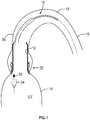
- a delivery catheter 10 is illustrated for delivery of a prosthetic cardiac valve 12 (e.g. a stent-valve) by an arterial approach to the heart 14.
- a prosthetic cardiac valve 12 e.g. a stent-valve
- the catheter 10 may be advanced through the descending aorta 16, around the aortic arch 18, and through the ascending aorta 20 to the aortic valve position 22 at the exit of the heart left ventricle LV.
- the prosthetic valve 12 is configured to be expandable from a collapsed condition (not shown) for delivery, to an expanded condition (as shown in Figs. 1 and 2 ) for implantation.
- the valve 12 may comprise a stent component supporting a valvular structure.
- the valve 12 is a self-expanding type valve that can be restrained in the collapsed condition by means of one or more sheaths 24 of the delivery catheter 10. When the one or more sheaths 24 are translated out of surrounding engagement with the valve 12, the valve 12 becomes free to self-expand at the implantation site.
- the valve 12 could be plastically expandable, and retained in collapsed form by its own internal strength when compressed (e.g. crimped).
- valve 12 More detail of an example valve 12 may be found it the aforementioned WO-A-2012032187 to which the reader is referred. Other constructions and geometries of expandable prosthetic valve 12 may be used as known in the art. An example of a valve (e.g. stent-valve) 12 is also described later with reference to Figs. 12-14
- Fig. 1 illustrates an example of a delivery catheter 10 having first and second constraining/deployment sheaths 24 for controlling the expansion of the valve 12.
- the sheaths 24 are translated in a controlled sequence for progressively releasing portions of the valve 12.
- the released portions of the valve self-expand in place.
- More detail of an example delivery catheter 12 having twin sheaths may be found in the aforementioned WO 2012038550 to which the reader is referred. More details may also be described later below with reference to Figs. 9-11 .
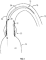
- Fig. 2 illustrates an alternative example of delivery catheter 12 having a single sheath 24 that is retracted in a direction away from the heart 14, to cause the valve 12 to expand progressively from bottom to top (in the schematic orientation of the drawing).
- the delivery catheter 12 may comprise a holder 30 having an engagement region 32 for restraining displacement of the valve 12 in at least one axial direction of the catheter 10, while at least a portion of the valve 12 is restrained in the collapsed condition around the holder 30.
- the holder 30 is useful to prevent the prosthetic valve 12 from jumping free of the delivery catheter 10 prematurely (for example, when only a small portion of the valve 12 remains constrained by the sheath 24). Premature jumping free may result in malpositioning of the valve 12, and subsequent inability to reposition and/or recapture the valve 12 by the delivery catheter 10.
- the holder 30 (or at least the engagement region 32) may be configured with a male and/or female engagement region 32, and/or an annular flange or wall, in order to mate with the valve 12 when in the collapsed state.
- the engagement region may comprise one or more projections, apertures or recesses that mate with complementary attachment elements (e.g. apertures or projections) of the valve 12. Expansion of the valve 12 moves the attachment elements to a wider radius than those of the holder, the intention being that the stent-valve 12 can release from the holder 30 upon expansion of the valve 12.
- An example of valve and attachments is described in more detail later.
- the valve may, for example, have two, three, four, or more attachment elements.
- the engagement region 32 of the holder 30 may have a corresponding number of engagement areas (for example, matching the number of attachment elements of the valve 12).
- the position of the holder 30 may vary according to the design of the valve 12 and/or the delivery catheter 10.
- the holder 30 is positioned at an operator-distal (heart-proximal) portion of a valve containment region of the delivery catheter, such that the holder 30 is directly adjacent to the heart 14.
- the holder 30 is positioned at an operator-proximal (heart-distal) portion of a valve containment region of the delivery catheter, such that the holder 30 is positioned in the ascending aorta.
- the delivery catheter 10 can tend to be placed or pressed (as a result of passing around the aortic arch 18), against a wall of the ascending aorta 20, and or the native valve site 22. It has been appreciated that in some cases (depending on the patient's individual anatomy, for example), such positioning can result in the holder 30 remaining engaged to a portion of the valve 12. Alternatively, there may be a risk of the holder 30 hooking a portion of the valve 12 during removal of the delivery catheter. It is believed that such engagement may explain at least some of the non-rare cases of valve dislodgement referred to in the introduction herein.
- the delivery catheter 10 (and optionally the holder 30) is configured to mitigate such issues.
- the stent holder 30 may comprise a body 40 including an engagement region 32.
- the engagement region 32 may be defined by one or a combination of any two or more of: projections 42; recesses 44; abutment wall 46.
- a multi-limbed device 50 may be provided, optionally as part of the holder 30 or associated therewith.
- the multi-limbed device 50 is biased to a deployed state (as shown in the drawings), in which the device can act as a fender (aforementioned aspect (b)), and/or a separator (aforementioned aspect (c)), and/or a disengagement device (e.g.
- the device 50 may be collapsible against the effect of the bias to a non-deployed state (not shown). For example, in the non-deployed state, the device 50 may be accommodated substantially flat against and/or at least partly within the profile of, the body 40.
- the device 50 may be of or comprise one or more of: resilient material; elastic material; pseudo-elastic material; shape-memory material (for example shape-memory alloy).
- the multi-limbed device 50 may comprise resiliently deformable limbs, fingers or elements 52.
- the deployed shape of each element 52 may be selected as desired.
- each element 52 generally comprises a ramp portion 54 that diverges from a hub 56 of the device 50, an apex 58 (e.g. defining a bulge shape), and a free end portion 60.
- the elements 52 are configured to be substantially non-interlocking with a said prosthetic valve. Additionally or alternatively, in some embodiments, the elements 52 are configured not to restrain a said prosthetic valve with respect to the holder.
- the number of elements 52 may optionally be at least three. Additionally or alternatively, the number of elements 52 equals or is greater than the number of engagement areas of the engagement region 32 of the holder 30.
- the elements 52 may extend axially across the engagement region 32, and extend at least partly beyond the engagement region 32 in both axial directions of the delivery catheter.
- the hub 56 may be in a region configured to be overlapped by a portion of a said prosthetic valve in use.
- At least some of the elements 52 include an aperture 62 through which the projection 42 of the holder can project.
- the hub 56 may be fixedly attached to the body 40 by means of a fixation sleeve 64.
- the free end portions 60 may slide (e.g. at least partly in an axial direction) in recesses 66 (e.g. elongate slots or grooves) of the body 40 in which the free end portions 60 are received.
- a cover (e.g. cap) 68 constrains the free end portions 66 captive, yet freely slidable in the recess 66.
- the cover 68 also prevents any risk of the free ends of the elements 52 causing damage to the valve 12 or to the native anatomy. Such risk might otherwise be present were free ends of a relatively thin element to be left exposed.
- the sliding movement of the end portions 60 permits the elements to elongate when transitioning to the non-deployed state.
- the radial compression force against the holder 30 may cause the elements 52 to collapse to their non-deployed state.
- the elements 52 do not obstruct substantially, or obscure substantially, the function of the engagement region 32.
- the elements 52 are pressed radially inwardly, such that the projections 42 project through the apertures 62, to engage the valve 12.
- the elements 52 are biased to transition to their deployed states, as illustrated in Figs. 3-5 .
- the elements 52 may bear outwardly against the valve 12 in order to urge the engagement region 32 of the holder 30 separate from the valve and/or eject the valve 12 clear of the engagement region 32.
- the elements 52 may act as a fender to urge the engagement region away from subsequent engagement with the valve 12.
- the elements 52 may substantially reduce (or completely reduce) the projection height of the projections.
- the elements 52 may change the outward shape or profile of the holder 30 to a shape that permits sliding contact with the valve 12 without re-engagement or hooking of the valve by the engagement region 32.
- the elements 52 may define a cage-like shroud over the engagement region 32.
- the elements 52 may deploy a ramp portion 52 that permits sliding contact, or acts as a guide to ramp the holder 30 over portions of the valve 12 that the holder 30 might otherwise be capable of hooking.
- Figs. 6 and 7 illustrate a further example comprising plural multi-limbed members 50a and 50b that are angularly offset with respect to each other. Such an arrangement can enable a greater number of elements 52 to be accommodated within the very confined space available around each hub 56.
- each device 50 may comprise three elements 52
- the combination of two devices 50a, 50b may collectively provide a cage-like structure of six elements 52.
- the body 40 of the holder 30 may comprise a corresponding number of accommodation recesses 66, for example, one for each element 52.
- the hubs 56 may have a keyed fit with respect to each other.
- the engagement portion 32 of the holder 30 may further include ramp sections 70 for additional ramping effect to avoid unintended re-engagement or hooking of the valve 12.
- the holder 30 may comprise one or more protective and/or friction-reducing flexible skirts or petals 72 to facilitate use of the catheter 10 and loading of a valve 12.
- the skirts or petals 72 may be illustrated for example in Fig. 5 , but may be omitted in other drawings to avoid obscuring other detail.
- the delivery catheter 10 comprises a stent holder 30, which may optionally be similar to any of the holders 30 described above, and include any of the examples of multi-limbed device 50 described above.
- the delivery catheter 10 further comprises at least one constraining sheath 24.
- the constraining sheath 24 is axially translatable between a first position (indicated by the arrow 100) in which the constraining sheath 24 surrounds at least a portion (and optionally the majority or substantially all) of the stent holder 30, and a second position (as illustrated in Fig. 8 ) in which the constraining sheath 24 does not surround the portion of the stent holder 30.
- the sheath 24 may translate in a distal direction of the delivery catheter, when moving from the first position to the second position.
- the sheath 24 may be a unique sheath of the delivery catheter 10, or it may be one (e.g. a distal sheath) of a multiple sheath (e.g. dual sheath) delivery catheter, for example, as described in the aforementioned WO-A-2012032187 , and in the example further below.
- the delivery catheter 10 further comprises an interface member 102.
- the interface member 102 may be associated with the stent holder 30. In some embodiments, the interface member 102 is carried by, or forms part of, the stent holder 30.
- the interface member 102 may be biased towards a radially expanded condition, as illustrated in Fig. 8 .
- the interface member 102 may serve to (i) bridge a gap between the holder 30 and the sheath 24 when in the second position, and/or (ii) defining a generally smooth interface surface between the holder 30 and the sheath 24 when in the second position.
- the interface member 102 may reduce any risk that a portion of the valve could become hooked in a gap between the sheath and the holder, during withdrawal of the delivery catheter after implantation of the prosthetic valve.
- the interface member 102 may bridge the gap and/or define a generally smooth interface surface, either or both of which reduce risk of hooking. This may apply especially when the sheath 24 is in the second position, but also when in the first position.
- the interface member 102 may be compressible to a radially collapsed condition (not shown) in order to fit within the sheath 24 when the sheath 24 is in the first position.
- the interface member 102 may expand to the radially expanded condition when the sheath 24 is translated to the second position.
- the interface member 102 may be reversibly deformable between the radially collapsed condition and the radially expandable condition.
- the interface member may be of or comprise one or more of: resilient material; elastic material; pseudo-elastic material; shape-memory material (for example shape-memory alloy.
- shape-memory material for example shape-memory alloy.
- An example shape-memory alloy is nitinol.
- the interface member 102 comprises a cage structure (or cage-like structure).
- the cage structure may comprise plural deformable struts 104.
- the struts may be coupled at at least one end to a hub 106, optionally to two hubs 106 at opposite ends in the form illustrated in Fig. 8 .
- the interface member 102 may have a generally bulbous shape in the radially expanded condition (as illustrated in Fig. 8 ), and a more cylindrical shape (even if not exactly cylindrical) in the radially collapsed condition (not shown).
- the interface member 102 may be integral with the multi-limbed device 50.
- the interface member 50 may be an extension of the multi-limbed device 50.
- the interface member 102 may move to the radially expanded condition at the same time as deployment of the multi-limbed device 50.
- the interface member 102 is distinct from the multi-limbed device 50.
- the tips of the limbs of the multi-limbed device 50 may be received within one hub 106.
- the other hub 106 may be capable of sliding axially in order to accommodate axial elongation of the interface member 102 when in the radially collapsed condition, but be retained by an axial stop 110 of the stent holder body.
- FIG. 9-11 an example delivery catheter incorporating any of the holders 30 described above is now described more completely, by way of information only.
- the delivery catheter is not limited to the following construction, although additional advantages may derive from using the holder 30 in the following construction of delivery catheter.
- a stent-valve 12 and a delivery catheter 10 therefor are illustrated in isolation.
- the delivery catheter 10 may have a distal portion 114 towards one end for insertion into a patient's anatomy, and a proximal portion 116 towards an opposite end from which the delivery catheter is manipulated in use by an operator.
- a barrel or stem portion 115 may extend between the distal and proximal portions.
- distal and proximal for the delivery catheter may refer to relative position with respect to an operator.
- the distal portion 114 of the catheter 112 may comprise an accommodation region 118 for accommodating the stent-valve 12 in a collapsed form for introduction into the anatomy.
- the stent-valve 12 may be a cardiac stent-valve.
- the delivery catheter 10 may be configured to permit delivery of the stent-valve 12 to, and deployment at, a desired site of implantation while the heart remains beating, for example, using a minimally invasive surgical and/or percutaneous procedure.
- the catheter 10 may be configured for introduction into the anatomical vascular system, and for advancement along the vasculature system to the desired site of implantation.
- the catheter 10 may be configured for introduction into the femoral artery, and guided retrograde via the descending aorta, aortic arch, and ascending aorta to the heart (sometimes called a transfemoral access).
- the catheter 10 may have a length of at least about 1m to provide sufficient length insertable into the anatomy.
- the catheter 10 may be insertable via the subclavian artery and guided retrograde to the heart (sometimes called transubclavian access).
- the catheter may be insertable via the ascending aorta (sometimes called transaortic access).
- the catheter 10 may be inserted directly into a chamber of the heart such as a ventricle (for example, left ventricle) via a direct access route while the heart remains beating.
- a direct access route may be through an aperture opened in the apex of the heart (sometimes called a transapical access).
- the size of access aperture into the anatomy may depend on the outer diameter of the distal portion 114.
- the barrel portion 115 may be slightly smaller than, or the same diameter as, the distal portion 114 as desired.
- An introducer 119 for example, a standard arterial introducer, may optionally be used at the access aperture into the anatomy.
- the optional introducer 119 may have a size of 20 French or smaller, for example, 18 French or smaller.
- the distal portion 114 may be dimensioned for insertion through such a size of introducer 119.
- the stent-valve 12 may be expandable from a compressed or collapsed condition to a functional and/or expanded condition, in order to anchor the stent-valve 12 at the implantation site.
- the stent-valve 12 may form a friction and/or interference fit with respect to the native anatomy.
- Various shapes and geometries of stent-valve 12 may be used to fit the anatomy at the site of implantation.
- a generally cylindrical stent-valve 12 is illustrated here for clarity, but the invention is not limited to a cylindrical shape, and may be especially advantageous with non-cylindrical shaped stent-valves 10.
- a more detailed example of stent-valve 12 is described later, and all details of the delivery catheter 10 are explicitly applicable to the stent-valve shape described later.
- the stent-valve 12 may be self-expanding and/or may be configured to be expandable by swelling of an expander (for example, a balloon not shown).
- Self-expanding stent-valves 12 may be constructed from, or use, shape-memory material, for example a shape-memory metal alloy (such as nitinol).
- a self-expanding stent-valve 10 may be retained in its compressed state by being constrained within a sheath 120/122 of the delivery catheter 10. Upon at least partial release from the sheath 120/122, the released portion of the stent-valve 12 may be free to expand.
- Non-self-expanding stent-valves 10 may also be made of shape-memory material, or from stainless steel, or cobalt-chromium alloy.
- a non-self-expanding stent-valve 12 may also be contained at least partly within a sheath 120/122 to protect the stent-valve 12 and/or facilitate smooth introduction through the anatomy.
- the distal portion 114 of the catheter 10 may comprise at least one sheath 120 and/or 122 that is translatable between a closed position at least partly covering the accommodation region 118 and/or the stent-valve 12 therein, and an open position at least partly opening or exposing the accommodation region 118 and/or at stent-valve 12 therein.
- the catheter 10 comprises two sheaths 120 and 122, both shown in their respective closed positions in Fig. 9 to at least partly (optionally substantially entirely) cover the stent-valve 12 in the accommodation region 118.
- the sheaths 120 and 122 may be translatable in opposite directions to respective open positions.
- a first e.g.
- first and second opposed sheaths 120 and 122 may provide good versatility for release of the stent-valve 10 from the accommodation region.
- a portion 110a of the stent-valve 12 previously covered by the second sheath 122 may be released (at least partly) before a portion 110b of the stent-valve 12 covered by the first sheath 120.
- the portion 110b may be released subsequently by translation of the first sheath 120 to or towards its open position ( Fig. 11 ).
- the length of the second sheath 122 may be greater than the length of the first sheath 120.
- the ratio of the second sheath length divided by the first sheath length may be at least 1.1, optionally at least 1.2, optionally at least 1.3, optionally at least 1.4, optionally at least 1.5, optionally at least 1.6, optionally at least 1.7, optionally at least 1.8, optionally at least 1.9, optionally at least 2.0, optionally at least 2.1, optionally at least 2.2, optionally at least 2.3, optionally at least 2.4, optionally at least 2.5, optionally at least 2.6, optionally at least 2.7, optionally at least 2.8, optionally at least 2.9, optionally at least 3, optionally at least 3.5, optionally at least 4 or optionally at least 4.5, or optionally at least 5.
- first sheath 120 may reduce risk of trauma in use.
- the first sheath 120 advances distally along a path that may be less controlled than the second sheath that benefits from a more controlled path defined by the path adopted by the barrel portion 115 of the catheter.
- the first sheath 120 may advance into the ventricle of the heart.
- Use of a relatively short first sheath 120 may reduce the degree to which the catheter 10 has to penetrate into the ventricle, and risk interfering with delicate tissue surfaces.
- direct access e.g. transapical access
- the first sheath 120 may advance into the ascending aorta.
- Use of a relatively short first sheath 120 may reduce the degree to which the first sheath 120 has to penetrate the space of the ascending aorta, and risk interfering with the aorta wall.
- One or both of the sheaths 120 and 122 may be of plastics optionally including reinforcement to resist radial expansion of the sheath.
- plastics is a poly ether block amide (PEBA), for example PEBAX (TM).
- PEBA poly ether block amide
- Reinforcement may be provided by a helical coil embedded within the sheath.
- the helical coil may be of metal, for example, stainless steel filament.
- the sheaths 120 and 122 may have the same inner and/or outer diameter.
- the sheaths 120 and 122 may be configured not to overlap each other. Avoiding an overlap can avoid excess diameter of the distal portion that might otherwise be caused by the sheath walls overlapping each other.
- the sheaths 120 and 122 may be capable of being positioned such that the sheaths 120 and 122 meet substantially end to end. Alternatively, the sheaths 120 and 122 may be configured such that the sheaths 120 and 122 remain spaced from each other, even in mutually closed positions of the first and second sheaths 20 and 22 when restraining a stent valve 12 ready for introduction into the body.
- the minimum spacing may be at least 1mm, or at least 2mm, or at least 3mm, or at least 4mm, or at least 5mm, or at least 6mm. Additionally or alternatively, the spacing may be less than 10mm, or less than 9mm, or less than 8mm, or less than 7mm, or less than 6mm, or less than 5mm. In one form, the spacing is between about 4mm and about 6mm.
- the stent-holder 30 may retain the stent-valve 12 axially in position and/or restrain the stent-valve 12 against axial movement.
- the stent-holder 30 is represented purely schematically in Figs. 9-11 , and may corresponds to any of the holder examples described hereinbefore.
- the stent-holder 30 may prevent and/or obstruct any tendency of the stent-valve 12 to be dragged by translation of a sheath 120 or 122.
- the stent-holder 30 may prevent and/or obstruct any tendency for a self-expanding stent-valve 12 to jump free of the catheter if only a small portion of the stent-valve 12 remains constrained by the sheath 120 or 122.
- the stent holder 30 may be positioned in the accommodation region 118 at a position appropriate to engage the stent-valve 12 until final release of the stent-valve 12 from the accommodation region.
- a distal portion of the stent-valve 12 may be intended to be released last, and the stent-holder 30 may be positioned towards the distal end of the accommodation region 118.
- the proximal portion of the stent-valve 12 if the proximal portion of the stent-valve 12 is intended to be released last, the stent-holder 30 could instead be positioned towards the proximal end of the accommodation region 118.
- the delivery catheter 10 may further comprise, at its proximal end, a control handle 130 including one or more actuators for manipulating the one or more sheaths 120/122.
- the actuators may generate relative axial movement which is transmitted to the sheaths via one or more nested tubes or shafts within the barrel.
- Figs. 12, 13 and 14 illustrate a detailed example of a stent-valve 12 for which the delivery catheter 10 of any of the preceding embodiments may be eminently suitable.
- the disclosure in not limited to the illustrated example of stent-valve, although additional advantages may follow from using the illustrated example.
- the stent-valve 12 may be of a self-expanding type that is resiliently biased towards the expanded and/or functional state, and is compressible to a compressed state by application of suitable radial compression forces.
- the stent-valve 12 remains in its compressed state while constrained. When the constraint is removed, the stent-valve 12 self expands towards the expanded and/or functional state.
- the stent-valve 12 may be of a non-self-expanding type that requires application of an expansion force to transform the stent-valve 12 from the compressed state to the expanded state.
- the stent-valve 12 may comprise a stent component supporting a plurality of valve leaflets 136.
- the leaflets 136 may collectively be referred to as a valve component, whether or not the leaflets 136 form an integral unit.
- the stent component may provide an anchoring function for anchoring the stent-valve in the native anatomy and/or a support function for supporting the valve leaflets 136.
- the stent component may be of any suitable material or materials.
- the stent component 14 may be of metal.
- Example materials include shape memory and/or superelastic alloys (for example, nitinol), stainless steel, or cobalt-chromium alloy.
- the stent component is self-expanding and is of shape memory/superelastic alloy (e.g. nitinol). However, the stent component could also be substantially non-self expanding.
- the stent component may have any profile desired for anchoring and/or aligning the stent-valve 12 with respect to the native anatomy at the desired implantation site.
- the stent component may be generally cylindrical in shape, or comprise one more generally cylindrical portions or portions lying on a generally cylindrical surface (e.g. 140c and 142a). Additionally or alternatively, the stent component may be generally non-cylindrical in shape or comprise one or more generally non-cylindrical portions or portions lying on a non-cylindrical surface (e.g. 140a, 140b, and 144). Additionally or alternatively, the stent component may comprise one or more anchor projections, and/or one or more stabilization portions.
- the stent component optionally has an inflow end and an outflow end, optionally is self-expandable from a compressed state for delivery towards a functional state upon implantation, the stent component comprising an outflow structure, for example, in the form of a plurality of arches 144a at the outflow end each having an apex at the outflow end, the stent component further comprising a crown (e.g. superior crown) 140b intermediate the inflow and outflow ends, the crown 140b having a free extremity intermediate the inflow and outflow ends and directed towards the outflow end, and the stent-component further comprising a fixation section (e.g. inferior crown) 140a between the crown and the inflow end.
- a fixation section e.g. inferior crown
- the stent component optionally comprises an anchoring portion 140 defined, for example, by an inferior crown 140a and a superior crown (or other fixation section) 140b that together define a groove and/or waist 140c therebetween.
- the anchoring portion 140 may have a first resistance to compression, and may comprise a cellular lattice.
- the stent component optionally (further) comprises a valve support portion 142 comprising, for example, a plurality (e.g. three) commissural support posts 142a.
- the commissural support posts 142a may be arranged on a pitch circle diameter smaller than an extremity of at least one of the crowns 140a and 140b.
- the commissural support posts 142a may be arranged on a pitch circle diameter corresponding to the waist 140c.
- the commissural support posts 142a may partly overlap at least one of the crowns 140 and 142 in the axial direction, and extend axially beyond that respective crown.
- the commissural support posts 142a may be frame-like.
- the commissural support posts 142a may have a shape that follows, at least approximately, a peripheral contour of the valve, at least in the region of the valve periphery adjacent to the commissural support posts.
- the stent component optionally (further) comprises a stabilization or alignment portion 144 which may represent an outflow structure.
- the portion 144 may be defined, for example, by a plurality (e.g. three) wings or arches 144a.
- the arches 144a may extend from tips of the commissural support posts 142a, to define a vaulted structure thereover.
- the alignment portion 144 may have a greater flexibility than the anchoring portion 140 and/or the valve support portion 142.
- the alignment portion 144 may have a second resistance to compression that is smaller than the first resistance to compression of the anchoring portion 140.
- the alignment portion 144 may be less rigid (e.g. radially) than the anchoring portion 140 and/or the valve support portion 142.
- the stent component optionally (further) comprises an attachment element for attaching the stent component to the stent holder 30 of the delivery catheter 10.
- the attachment portion is defined by a plurality (e.g. three) of extensions of cells of the inferior crown 140a, and have a shape corresponding to a completely or partly enclosed attachment eyes.
- the valve component or leaflets 136 may be of any suitable natural and/or synthetic material(s).
- the valve component/leaflets 136 may comprise porcine and/or bovine pericardium and/or harvested natural valve material.
- the leaflets may be supported to coapt or collapse to a closed position to obstruct flow in one direction therepast, while flexing apart to an open position to allow flow in an opposite direction.
- the valve component/leaflets 136 may be accommodated at the valve support portion 142 and/or at least partly within the anchoring portion 140.
- the leaflets may have side tabs. The tabs of adjacent pairs of leaflets may pass in pairs through slots in the support posts 142, be folded back and sutured on either side of the slot.
- the support posts 142a may have lines of suture holes either side of the slot to accommodate the sutures. Further suture holes may be provided above and/or below the slots. If desired the suture hole above the slot (indicated at A in Fig. 14 ) and/or the suture hole below the slot, may be omitted to save space.
- the stent-valve 12 may further comprise an inner skirt and/or an outer skirt covering at least partly a respective inner or outer surface portion of the stent component.
- the skirt(s) may cover at least a portion of the anchoring portion 140 and/or at least a portion of the valve support portion 142.
- the skirt(s) may be made of any suitable material, including PET and/or pericardium.
- the pericardium may be of the same material as the leaflets.
- the inner and outer skirts may partly overlap each other in a skirt overlap region in Fig. 12 , and include non-overlapping portions extending axially above and below, respectively, the overlap region.
- the inner skirt may be advantageous in channel blood towards the leaflets and preventing leakage of blood through the interstices of the lattice structure.
- the outer skirt may be advantageous in preventing leakage of blood at the interface between the stent-valve and surrounding tissue.
- a method of releasing the stent-valve 12 may include moving the second sheath 120 to an open position in order to deploy the crown / superior crown 140b, followed by the support section 142, and finally the arches 144a. For example, these elements may be deployed on an aorta side of a native and/or failed valve.
- the first sheath 120 may be moved to its open position in order to deploy the inferior crown 140a.
- the attachment elements may release from the stent-holder 30, optoinally under the effects of the member 50 provided in the holder 30.
- the arches may be configured for aligning the stent-valve with respect to an axis of the ascending aorta by contact with a wall of the ascending aorta.
- the arches may be bendable independently of each other.
- the crown may be configured for engaging and/or seating against existing leaflets from an outflow side.
- the fixation section may be configured for engaging an existing annulus. Deploying the arches before the fixation section may permit self-alignment of the stent-valve by the action of the arches, before the fixation section deploys to anchor the stent-valve at the annulus of the existing valve.
Landscapes
- Health & Medical Sciences (AREA)
- Cardiology (AREA)
- Oral & Maxillofacial Surgery (AREA)
- Transplantation (AREA)
- Engineering & Computer Science (AREA)
- Biomedical Technology (AREA)
- Heart & Thoracic Surgery (AREA)
- Vascular Medicine (AREA)
- Life Sciences & Earth Sciences (AREA)
- Animal Behavior & Ethology (AREA)
- General Health & Medical Sciences (AREA)
- Public Health (AREA)
- Veterinary Medicine (AREA)
- Prostheses (AREA)
Claims (15)
- Einführungskatheter (10) für eine Herzklappenprothese (12), wobei die Klappe (12) aus einem kollabierten Zustand zur Einführung in einen expandierten Zustand zur Implantation expandierbar ist, wobei der Einführungskatheter (10) folgendes umfasst:einen Halter (30) mit einer Eingriffsregion (32) für einen Eingriff mit zumindest einem Abschnitt der Herzklappenprothese (12) zur Beschränkung einer axialen Verschiebung der Klappenprothese (12) in zumindest einer axialen Richtung des Katheters (10), wenn sich die Klappe (12) im kollabierten Zustand um den Halter (30) befindet, gekennzeichnet durchzumindest ein Element (52), das derart vorgespannt ist, dass es von einem nicht eingesetzten Zustand, in dem das Element (52) bezüglich eines Abschnitts des Halters (30) nicht wesentlich nach außen ragt, in einen eingesetzten Zustand, in dem das zumindest eine Element (52) bezüglich eines Abschnitts des Halters (30) wesentlich nach außen ragt, übergeht,wobei das zumindest eine Element (52) eine Öffnung (62) umfasst, durch die ein Vorsprung (42) des Halters (30) im nicht eingesetzten Zustand vorragen kann.
- Einführungskatheter (10) nach Anspruch 1, wobei die Eingriffsregion (32) des Halters (30) eine oder mehrere männliche Eingriffsregionen umfasst, die von einem jeweiligen Vorsprung für ineinanderpassenden und/oder verriegelnden Eingriff mit der Klappenprothese (12) definiert werden, und wobei das zumindest eine Element (52) eine mit der Eingriffsregion (32) in Zusammenhang stehende Anschlagfläche definiert, die bezüglich der Eingriffsregion (32) relativ beweglich sind.
- Einführungskatheter (10) nach einem der vorhergehenden Ansprüche, umfassend eine Vielzahl von mit dem Halter (30) in Zusammenhang stehenden Elementen (52), wobei die Elemente (52) in einen radial nach außen eingesetzten Zustand vorgespannt sind, und unter einer radialen Kompressionskraft in einen radial nicht eingesetzten Zustand kollabierbar sind, in dem zumindest ein Abschnitt jedes Elements (52) in eine Position bewegt wird, die ein kleineres radiales Profil als im eingesetzten Zustand definiert.
- Einführungskatheter nach Anspruch 3, wobei die Elemente (52) eines oder mehrere der folgenden sind: (i) dazu ausgelegt, mit einer besagten Klappenprothese (12) im Wesentlichen nicht zu verriegeln; und/oder (ii) dazu ausgelegt, eine besagte Klappenprothese (12) bezüglich des Halters (30) nicht zurückzuhalten.
- Einführungskatheter (10) nach Anspruch 3 oder 4, wobei die Anzahl der Elemente (52) mindestens drei beträgt.
- Einführungskatheter (10) nach Anspruch 3, 4 oder 5, wobei die Anzahl der Elemente (52) einer Anzahl von Eingriffsflächen der Eingriffsregion (32) des Halters (30) entspricht oder größer ist als diese, wobei jede Eingriffsfläche dazu ausgelegt ist, von einem Befestigungselement einer besagten Herzklappenprothese (12) in Eingriff genommen zu werden.
- Einführungskatheter (10) nach Anspruch 3 oder einem davon abhängigen Anspruch, wobei zumindest eines der Elemente (52) eine besagte Öffnung (62) in Deckung mit einem männlichen Vorsprung (42) des Halters (30) umfasst.
- Einführungskatheter (10) nach Anspruch 3 oder einem davon abhängigen Anspruch, wobei sich die Elemente (52) axial über die Eingriffsregion (32) erstrecken und sich zumindest teilweise über die Eingriffsregion (32) hinaus in beide axialen Richtungen des Einführungskatheters (10) erstrecken.
- Einführungskatheter (10) nach Anspruch 3 oder einem davon abhängigen Anspruch, wobei zumindest einige der Elemente (52) mit einem gemeinsamen Ansatz (56) verbunden oder einstückig sind, und wobei der Ansatz (56) axial zu einer Seite des Halters (30) angeordnet ist, wobei sich der Ansatz (56) in einer Region befindet, die dazu ausgelegt ist, im Gebrauch von einem Abschnitt einer besagten Klappenprothese (12) überlappt zu werden.
- Einführungskatheter (10) nach Anspruch 3 oder einem davon abhängigen Anspruch, wobei zumindest ein Ende zumindest einiger Elemente (52) freie Ende (60) sind, und wobei der Halter (30) ferner eine Abdeckung (68) zum Abdecken und/oder Zurückhalten der freien Enden (60) der Elemente (52) umfasst.
- Einführungskatheter (10) für eine Herzklappenprothese nach einem der Ansprüche 1 bis 10, ferner umfassend
eine Hülle (24), die bezüglich des Halters (30) zwischen einer ersten Position, in der die Hülle (24) zumindest einen ersten Abschnitt des Halters (30) umgibt, und einer zweiten Position, in der die Hülle (24) den ersten Abschnitt des Halters (30) nicht umgibt, verschiebbar ist; und
ein Schnittstellenelement (102), das in einen radial expandierten Zustand vorgespannt ist, um (i) einen Spalt zwischen dem Halter (30) und der Hülle (24) in der zweiten Position zu überbrücken, und/oder (ii) eine allgemein glatte Schnittstellenfläche zwischen dem Halter (30) und der Hülle (24) in der zweiten Position zu definieren. - Einführungskatheter (10) nach Anspruch 11, wobei das Schnittstellenelement (102) mit dem Halter (30) in Zusammenhang steht.
- Einführungskatheter (10) nach Anspruch 11 oder 12, wobei die Hülle (24) in eine distale Richtung des Einführungskatheters (10) verschoben wird, wenn sie sich aus der ersten Position in die zweite Position bewegt.
- Einführungskatheter (10) nach einem der Ansprüche 11 bis 13, wobei das Schnittstellenelement (102) eine allgemein bauchige Gestalt im radial expandierten Zustand und eine weniger bauchige Gestalt im radial kollabierten Zustand aufweist.
- Einführungskatheter (10) nach einem der Ansprüche 11 bis 14, wobei das Schnittstellenelement (102) eine Käfigstruktur mit mehreren Streben (104) aufweist.
Priority Applications (2)
| Application Number | Priority Date | Filing Date | Title |
|---|---|---|---|
| EP17173533.5A EP3231395B1 (de) | 2013-02-06 | 2014-02-06 | Klappenprothese und abgabevorrichtung |
| EP14702869.0A EP2953579B1 (de) | 2013-02-06 | 2014-02-06 | Einführvorrichtuing für eine klappenprothese |
Applications Claiming Priority (4)
| Application Number | Priority Date | Filing Date | Title |
|---|---|---|---|
| EP13000597 | 2013-02-06 | ||
| EP13190553 | 2013-10-28 | ||
| PCT/EP2014/052311 WO2014122205A1 (en) | 2013-02-06 | 2014-02-06 | Prosthetic valve, delivery apparatus and delivery method |
| EP14702869.0A EP2953579B1 (de) | 2013-02-06 | 2014-02-06 | Einführvorrichtuing für eine klappenprothese |
Related Child Applications (1)
| Application Number | Title | Priority Date | Filing Date |
|---|---|---|---|
| EP17173533.5A Division EP3231395B1 (de) | 2013-02-06 | 2014-02-06 | Klappenprothese und abgabevorrichtung |
Publications (2)
| Publication Number | Publication Date |
|---|---|
| EP2953579A1 EP2953579A1 (de) | 2015-12-16 |
| EP2953579B1 true EP2953579B1 (de) | 2017-05-31 |
Family
ID=50064620
Family Applications (2)
| Application Number | Title | Priority Date | Filing Date |
|---|---|---|---|
| EP14702869.0A Active EP2953579B1 (de) | 2013-02-06 | 2014-02-06 | Einführvorrichtuing für eine klappenprothese |
| EP17173533.5A Active EP3231395B1 (de) | 2013-02-06 | 2014-02-06 | Klappenprothese und abgabevorrichtung |
Family Applications After (1)
| Application Number | Title | Priority Date | Filing Date |
|---|---|---|---|
| EP17173533.5A Active EP3231395B1 (de) | 2013-02-06 | 2014-02-06 | Klappenprothese und abgabevorrichtung |
Country Status (8)
| Country | Link |
|---|---|
| US (1) | US10285811B2 (de) |
| EP (2) | EP2953579B1 (de) |
| JP (1) | JP2016506804A (de) |
| CN (1) | CN104968300A (de) |
| AU (1) | AU2014213982A1 (de) |
| BR (1) | BR112015018310A2 (de) |
| CA (1) | CA2899447C (de) |
| WO (1) | WO2014122205A1 (de) |
Cited By (15)
| Publication number | Priority date | Publication date | Assignee | Title |
|---|---|---|---|---|
| US10856984B2 (en) | 2017-08-25 | 2020-12-08 | Neovasc Tiara Inc. | Sequentially deployed transcatheter mitral valve prosthesis |
| US10940001B2 (en) | 2012-05-30 | 2021-03-09 | Neovasc Tiara Inc. | Methods and apparatus for loading a prosthesis onto a delivery system |
| US11311376B2 (en) | 2019-06-20 | 2022-04-26 | Neovase Tiara Inc. | Low profile prosthetic mitral valve |
| US11357622B2 (en) | 2016-01-29 | 2022-06-14 | Neovase Tiara Inc. | Prosthetic valve for avoiding obstruction of outflow |
| US11389291B2 (en) | 2013-04-04 | 2022-07-19 | Neovase Tiara Inc. | Methods and apparatus for delivering a prosthetic valve to a beating heart |
| US11413139B2 (en) | 2011-11-23 | 2022-08-16 | Neovasc Tiara Inc. | Sequentially deployed transcatheter mitral valve prosthesis |
| US11419720B2 (en) | 2010-05-05 | 2022-08-23 | Neovasc Tiara Inc. | Transcatheter mitral valve prosthesis |
| US11464631B2 (en) | 2016-11-21 | 2022-10-11 | Neovasc Tiara Inc. | Methods and systems for rapid retraction of a transcatheter heart valve delivery system |
| US11491006B2 (en) | 2019-04-10 | 2022-11-08 | Neovasc Tiara Inc. | Prosthetic valve with natural blood flow |
| US11497602B2 (en) | 2012-02-14 | 2022-11-15 | Neovasc Tiara Inc. | Methods and apparatus for engaging a valve prosthesis with tissue |
| US11602429B2 (en) | 2019-04-01 | 2023-03-14 | Neovasc Tiara Inc. | Controllably deployable prosthetic valve |
| US11737872B2 (en) | 2018-11-08 | 2023-08-29 | Neovasc Tiara Inc. | Ventricular deployment of a transcatheter mitral valve prosthesis |
| US11779742B2 (en) | 2019-05-20 | 2023-10-10 | Neovasc Tiara Inc. | Introducer with hemostasis mechanism |
| US11998447B2 (en) | 2019-03-08 | 2024-06-04 | Neovasc Tiara Inc. | Retrievable prosthesis delivery system |
| US12109111B2 (en) | 2015-12-15 | 2024-10-08 | Neovasc Tiara Inc. | Transseptal delivery system |
Families Citing this family (23)
| Publication number | Priority date | Publication date | Assignee | Title |
|---|---|---|---|---|
| US10390943B2 (en) | 2014-03-17 | 2019-08-27 | Evalve, Inc. | Double orifice device for transcatheter mitral valve replacement |
| JP6858337B2 (ja) * | 2014-12-05 | 2021-04-14 | エヌヴィーティー アーゲー | 人工心臓弁システムおよび該システムのための送達システム |
| EP3679895A1 (de) * | 2015-07-02 | 2020-07-15 | Boston Scientific Scimed, Inc. | Justierbare konische spitze |
| US10335277B2 (en) | 2015-07-02 | 2019-07-02 | Boston Scientific Scimed Inc. | Adjustable nosecone |
| CN113367788B (zh) * | 2015-10-26 | 2024-09-06 | 纽韦弗医疗设备公司 | 能量递送系统及其用途 |
| US10363138B2 (en) | 2016-11-09 | 2019-07-30 | Evalve, Inc. | Devices for adjusting the curvature of cardiac valve structures |
| US10426616B2 (en) * | 2016-11-17 | 2019-10-01 | Evalve, Inc. | Cardiac implant delivery system |
| US10653523B2 (en) | 2017-01-19 | 2020-05-19 | 4C Medical Technologies, Inc. | Systems, methods and devices for delivery systems, methods and devices for implanting prosthetic heart valves |
| US10561495B2 (en) | 2017-01-24 | 2020-02-18 | 4C Medical Technologies, Inc. | Systems, methods and devices for two-step delivery and implantation of prosthetic heart valve |
| US12029647B2 (en) | 2017-03-07 | 2024-07-09 | 4C Medical Technologies, Inc. | Systems, methods and devices for prosthetic heart valve with single valve leaflet |
| US10667934B2 (en) | 2017-04-04 | 2020-06-02 | Medtronic Vascular, Inc. | System for loading a transcatheter valve prosthesis into a delivery catheter |
| US12036113B2 (en) | 2017-06-14 | 2024-07-16 | 4C Medical Technologies, Inc. | Delivery of heart chamber prosthetic valve implant |
| CN109692057B (zh) * | 2017-10-24 | 2023-07-14 | 杭州启明医疗器械股份有限公司 | 一种便于回收控制的介入器械输送装置 |
| EP3700468A1 (de) | 2017-10-25 | 2020-09-02 | Boston Scientific Scimed, Inc. | Schleuse zur freisetzung einer herzklappe, system und verfahren |
| CN110292463B (zh) * | 2018-03-22 | 2024-08-23 | 上海微创心通医疗科技有限公司 | 一种植入体的装载装置 |
| CN110314016B (zh) * | 2018-03-30 | 2024-02-27 | 康迪泰科(北京)医疗科技有限公司 | 一种瓣膜输送装置及其输送系统 |
| EP3569201B1 (de) * | 2018-05-17 | 2023-04-05 | Creganna Unlimited Company | Kraftbegrenzungsgriffanordnung und herzkatheterbasiertes fördersystem |
| US11857441B2 (en) | 2018-09-04 | 2024-01-02 | 4C Medical Technologies, Inc. | Stent loading device |
| US11241312B2 (en) | 2018-12-10 | 2022-02-08 | Boston Scientific Scimed, Inc. | Medical device delivery system including a resistance member |
| US11931253B2 (en) | 2020-01-31 | 2024-03-19 | 4C Medical Technologies, Inc. | Prosthetic heart valve delivery system: ball-slide attachment |
| US12053375B2 (en) | 2020-03-05 | 2024-08-06 | 4C Medical Technologies, Inc. | Prosthetic mitral valve with improved atrial and/or annular apposition and paravalvular leakage mitigation |
| US11992403B2 (en) | 2020-03-06 | 2024-05-28 | 4C Medical Technologies, Inc. | Devices, systems and methods for improving recapture of prosthetic heart valve device with stent frame having valve support with inwardly stent cells |
| CN114081669A (zh) * | 2020-08-25 | 2022-02-25 | 北京市普惠生物医学工程有限公司 | 人工瓣膜及瓣膜输送系统 |
Citations (6)
| Publication number | Priority date | Publication date | Assignee | Title |
|---|---|---|---|---|
| WO2007047488A2 (en) | 2005-10-18 | 2007-04-26 | Edwards Lifesciences Corporation | Heart valve delivery system with valve catheter |
| US20100049313A1 (en) | 2008-08-22 | 2010-02-25 | Edwards Lifesciences Corporation | Prosthetic heart valve and delivery apparatus |
| WO2011025945A1 (en) | 2009-08-27 | 2011-03-03 | Medtronic Inc. | Transcatheter valve delivery systems and methods |
| US20110264202A1 (en) | 2010-04-27 | 2011-10-27 | Medtronic Vascular, Inc. | Transcatheter Prosthetic Heart Valve Delivery Device with Biased Release Features |
| WO2012009006A1 (en) | 2010-07-15 | 2012-01-19 | St. Jude Medical, Inc. | Retainers for transcatheter heart valve delivery systems |
| WO2012038550A1 (en) | 2010-09-24 | 2012-03-29 | Symetis Sa | Stent valve, delivery apparatus and method therefor |
Family Cites Families (4)
| Publication number | Priority date | Publication date | Assignee | Title |
|---|---|---|---|---|
| WO2007071436A2 (en) | 2005-12-22 | 2007-06-28 | Symetis Sa | Stent-valves for valve replacement and associated methods and systems for surgery |
| EP2679198B1 (de) | 2007-10-25 | 2021-03-24 | Symetis SA | Stents mit Klappen und Systeme für zur deren Einführung |
| US9561102B2 (en) | 2010-06-02 | 2017-02-07 | Medtronic, Inc. | Transcatheter delivery system and method with controlled expansion and contraction of prosthetic heart valve |
| JP5931880B2 (ja) | 2010-09-10 | 2016-06-08 | シメティス・ソシエテ・アノニムSymetis Sa | 弁置換装置、弁置換装置とその送達装置とを備えるシステム、および弁置換装置の製造方法 |
-
2014
- 2014-02-06 EP EP14702869.0A patent/EP2953579B1/de active Active
- 2014-02-06 AU AU2014213982A patent/AU2014213982A1/en not_active Abandoned
- 2014-02-06 CA CA2899447A patent/CA2899447C/en not_active Expired - Fee Related
- 2014-02-06 CN CN201480007679.5A patent/CN104968300A/zh active Pending
- 2014-02-06 EP EP17173533.5A patent/EP3231395B1/de active Active
- 2014-02-06 BR BR112015018310A patent/BR112015018310A2/pt active Search and Examination
- 2014-02-06 JP JP2015556488A patent/JP2016506804A/ja active Pending
- 2014-02-06 WO PCT/EP2014/052311 patent/WO2014122205A1/en active Application Filing
- 2014-02-06 US US14/766,417 patent/US10285811B2/en active Active
Patent Citations (6)
| Publication number | Priority date | Publication date | Assignee | Title |
|---|---|---|---|---|
| WO2007047488A2 (en) | 2005-10-18 | 2007-04-26 | Edwards Lifesciences Corporation | Heart valve delivery system with valve catheter |
| US20100049313A1 (en) | 2008-08-22 | 2010-02-25 | Edwards Lifesciences Corporation | Prosthetic heart valve and delivery apparatus |
| WO2011025945A1 (en) | 2009-08-27 | 2011-03-03 | Medtronic Inc. | Transcatheter valve delivery systems and methods |
| US20110264202A1 (en) | 2010-04-27 | 2011-10-27 | Medtronic Vascular, Inc. | Transcatheter Prosthetic Heart Valve Delivery Device with Biased Release Features |
| WO2012009006A1 (en) | 2010-07-15 | 2012-01-19 | St. Jude Medical, Inc. | Retainers for transcatheter heart valve delivery systems |
| WO2012038550A1 (en) | 2010-09-24 | 2012-03-29 | Symetis Sa | Stent valve, delivery apparatus and method therefor |
Cited By (21)
| Publication number | Priority date | Publication date | Assignee | Title |
|---|---|---|---|---|
| US11419720B2 (en) | 2010-05-05 | 2022-08-23 | Neovasc Tiara Inc. | Transcatheter mitral valve prosthesis |
| US11413139B2 (en) | 2011-11-23 | 2022-08-16 | Neovasc Tiara Inc. | Sequentially deployed transcatheter mitral valve prosthesis |
| US12053369B2 (en) | 2011-11-23 | 2024-08-06 | Neovasc Tiara Inc. | Sequentially deployed transcatheter mitral valve prosthesis |
| US11497602B2 (en) | 2012-02-14 | 2022-11-15 | Neovasc Tiara Inc. | Methods and apparatus for engaging a valve prosthesis with tissue |
| US11389294B2 (en) | 2012-05-30 | 2022-07-19 | Neovasc Tiara Inc. | Methods and apparatus for loading a prosthesis onto a delivery system |
| US10940001B2 (en) | 2012-05-30 | 2021-03-09 | Neovasc Tiara Inc. | Methods and apparatus for loading a prosthesis onto a delivery system |
| US11617650B2 (en) | 2012-05-30 | 2023-04-04 | Neovasc Tiara Inc. | Methods and apparatus for loading a prosthesis onto a delivery system |
| US11389291B2 (en) | 2013-04-04 | 2022-07-19 | Neovase Tiara Inc. | Methods and apparatus for delivering a prosthetic valve to a beating heart |
| US12109111B2 (en) | 2015-12-15 | 2024-10-08 | Neovasc Tiara Inc. | Transseptal delivery system |
| US11357622B2 (en) | 2016-01-29 | 2022-06-14 | Neovase Tiara Inc. | Prosthetic valve for avoiding obstruction of outflow |
| US11464631B2 (en) | 2016-11-21 | 2022-10-11 | Neovasc Tiara Inc. | Methods and systems for rapid retraction of a transcatheter heart valve delivery system |
| US11793640B2 (en) | 2017-08-25 | 2023-10-24 | Neovasc Tiara Inc. | Sequentially deployed transcatheter mitral valve prosthesis |
| US10856984B2 (en) | 2017-08-25 | 2020-12-08 | Neovasc Tiara Inc. | Sequentially deployed transcatheter mitral valve prosthesis |
| US11737872B2 (en) | 2018-11-08 | 2023-08-29 | Neovasc Tiara Inc. | Ventricular deployment of a transcatheter mitral valve prosthesis |
| US11998447B2 (en) | 2019-03-08 | 2024-06-04 | Neovasc Tiara Inc. | Retrievable prosthesis delivery system |
| US11602429B2 (en) | 2019-04-01 | 2023-03-14 | Neovasc Tiara Inc. | Controllably deployable prosthetic valve |
| US12036117B2 (en) | 2019-04-10 | 2024-07-16 | Neovasc Tiara Inc. | Prosthetic valve with natural blood flow |
| US11491006B2 (en) | 2019-04-10 | 2022-11-08 | Neovasc Tiara Inc. | Prosthetic valve with natural blood flow |
| US11779742B2 (en) | 2019-05-20 | 2023-10-10 | Neovasc Tiara Inc. | Introducer with hemostasis mechanism |
| US11931254B2 (en) | 2019-06-20 | 2024-03-19 | Neovasc Tiara Inc. | Low profile prosthetic mitral valve |
| US11311376B2 (en) | 2019-06-20 | 2022-04-26 | Neovase Tiara Inc. | Low profile prosthetic mitral valve |
Also Published As
| Publication number | Publication date |
|---|---|
| CA2899447A1 (en) | 2014-08-14 |
| EP3231395B1 (de) | 2022-08-24 |
| BR112015018310A2 (pt) | 2017-07-18 |
| EP2953579A1 (de) | 2015-12-16 |
| US10285811B2 (en) | 2019-05-14 |
| CN104968300A (zh) | 2015-10-07 |
| AU2014213982A1 (en) | 2015-08-13 |
| CA2899447C (en) | 2020-11-03 |
| EP3231395A1 (de) | 2017-10-18 |
| JP2016506804A (ja) | 2016-03-07 |
| WO2014122205A1 (en) | 2014-08-14 |
| US20150366665A1 (en) | 2015-12-24 |
Similar Documents
| Publication | Publication Date | Title |
|---|---|---|
| US20230338141A1 (en) | Prosthetic valve, delivery apparatus and delivery method | |
| EP2953579B1 (de) | Einführvorrichtuing für eine klappenprothese | |
| US20220133476A1 (en) | Stent valve, delivery apparatus and method therefor | |
| US20240058125A1 (en) | Transcatheter delivery system and method with controlled expansion and contraction of prosthetic heart valve | |
| EP2900176B1 (de) | Stentklappe, freisetzungsvorrichtung und stenthalter dafür | |
| EP2663259B1 (de) | System zur retrograden perikardialen freisetzung einer herzklappenprothese | |
| US9999501B2 (en) | Valve prosthesis | |
| JP5947285B2 (ja) | 拡張型安定管を有する経カテーテル補綴心臓弁送達システム | |
| CA2941398A1 (en) | Transcatheter mitral valve stent frames | |
| CN113164254B (zh) | 人工瓣膜递送组件 | |
| US20240156595A1 (en) | Delivery System for Self-Expanding Valve with Exposed Cuff | |
| EP3673871B1 (de) | Implantationssystem von transkatheter-aortenklappen | |
| CN116096331A (zh) | 用于假体医学装置的递送设备的囊体 |
Legal Events
| Date | Code | Title | Description |
|---|---|---|---|
| PUAI | Public reference made under article 153(3) epc to a published international application that has entered the european phase |
Free format text: ORIGINAL CODE: 0009012 |
|
| 17P | Request for examination filed |
Effective date: 20150831 |
|
| AK | Designated contracting states |
Kind code of ref document: A1 Designated state(s): AL AT BE BG CH CY CZ DE DK EE ES FI FR GB GR HR HU IE IS IT LI LT LU LV MC MK MT NL NO PL PT RO RS SE SI SK SM TR |
|
| AX | Request for extension of the european patent |
Extension state: BA ME |
|
| DAX | Request for extension of the european patent (deleted) | ||
| GRAP | Despatch of communication of intention to grant a patent |
Free format text: ORIGINAL CODE: EPIDOSNIGR1 |
|
| STAA | Information on the status of an ep patent application or granted ep patent |
Free format text: STATUS: GRANT OF PATENT IS INTENDED |
|
| RIC1 | Information provided on ipc code assigned before grant |
Ipc: A61F 2/97 20130101ALN20161202BHEP Ipc: A61F 2/24 20060101AFI20161202BHEP |
|
| INTG | Intention to grant announced |
Effective date: 20161223 |
|
| RIN1 | Information on inventor provided before grant (corrected) |
Inventor name: HEFTI, JEAN-LUC Inventor name: DELALOYE, STEPHANE Inventor name: MANTANUS, LUC Inventor name: LOMBARDI, FABIEN Inventor name: BIADILLAH, YOUSSEF |
|
| GRAS | Grant fee paid |
Free format text: ORIGINAL CODE: EPIDOSNIGR3 |
|
| GRAA | (expected) grant |
Free format text: ORIGINAL CODE: 0009210 |
|
| STAA | Information on the status of an ep patent application or granted ep patent |
Free format text: STATUS: THE PATENT HAS BEEN GRANTED |
|
| AK | Designated contracting states |
Kind code of ref document: B1 Designated state(s): AL AT BE BG CH CY CZ DE DK EE ES FI FR GB GR HR HU IE IS IT LI LT LU LV MC MK MT NL NO PL PT RO RS SE SI SK SM TR |
|
| REG | Reference to a national code |
Ref country code: CH Ref legal event code: EP Ref country code: GB Ref legal event code: FG4D |
|
| REG | Reference to a national code |
Ref country code: AT Ref legal event code: REF Ref document number: 896745 Country of ref document: AT Kind code of ref document: T Effective date: 20170615 |
|
| REG | Reference to a national code |
Ref country code: IE Ref legal event code: FG4D |
|
| REG | Reference to a national code |
Ref country code: DE Ref legal event code: R096 Ref document number: 602014010253 Country of ref document: DE |
|
| REG | Reference to a national code |
Ref country code: NL Ref legal event code: FP |
|
| REG | Reference to a national code |
Ref country code: LT Ref legal event code: MG4D |
|
| REG | Reference to a national code |
Ref country code: AT Ref legal event code: MK05 Ref document number: 896745 Country of ref document: AT Kind code of ref document: T Effective date: 20170531 |
|
| PG25 | Lapsed in a contracting state [announced via postgrant information from national office to epo] |
Ref country code: LT Free format text: LAPSE BECAUSE OF FAILURE TO SUBMIT A TRANSLATION OF THE DESCRIPTION OR TO PAY THE FEE WITHIN THE PRESCRIBED TIME-LIMIT Effective date: 20170531 Ref country code: NO Free format text: LAPSE BECAUSE OF FAILURE TO SUBMIT A TRANSLATION OF THE DESCRIPTION OR TO PAY THE FEE WITHIN THE PRESCRIBED TIME-LIMIT Effective date: 20170831 Ref country code: ES Free format text: LAPSE BECAUSE OF FAILURE TO SUBMIT A TRANSLATION OF THE DESCRIPTION OR TO PAY THE FEE WITHIN THE PRESCRIBED TIME-LIMIT Effective date: 20170531 Ref country code: HR Free format text: LAPSE BECAUSE OF FAILURE TO SUBMIT A TRANSLATION OF THE DESCRIPTION OR TO PAY THE FEE WITHIN THE PRESCRIBED TIME-LIMIT Effective date: 20170531 Ref country code: FI Free format text: LAPSE BECAUSE OF FAILURE TO SUBMIT A TRANSLATION OF THE DESCRIPTION OR TO PAY THE FEE WITHIN THE PRESCRIBED TIME-LIMIT Effective date: 20170531 Ref country code: AT Free format text: LAPSE BECAUSE OF FAILURE TO SUBMIT A TRANSLATION OF THE DESCRIPTION OR TO PAY THE FEE WITHIN THE PRESCRIBED TIME-LIMIT Effective date: 20170531 Ref country code: GR Free format text: LAPSE BECAUSE OF FAILURE TO SUBMIT A TRANSLATION OF THE DESCRIPTION OR TO PAY THE FEE WITHIN THE PRESCRIBED TIME-LIMIT Effective date: 20170901 |
|
| PG25 | Lapsed in a contracting state [announced via postgrant information from national office to epo] |
Ref country code: SE Free format text: LAPSE BECAUSE OF FAILURE TO SUBMIT A TRANSLATION OF THE DESCRIPTION OR TO PAY THE FEE WITHIN THE PRESCRIBED TIME-LIMIT Effective date: 20170531 Ref country code: IS Free format text: LAPSE BECAUSE OF FAILURE TO SUBMIT A TRANSLATION OF THE DESCRIPTION OR TO PAY THE FEE WITHIN THE PRESCRIBED TIME-LIMIT Effective date: 20170930 Ref country code: BG Free format text: LAPSE BECAUSE OF FAILURE TO SUBMIT A TRANSLATION OF THE DESCRIPTION OR TO PAY THE FEE WITHIN THE PRESCRIBED TIME-LIMIT Effective date: 20170831 Ref country code: RS Free format text: LAPSE BECAUSE OF FAILURE TO SUBMIT A TRANSLATION OF THE DESCRIPTION OR TO PAY THE FEE WITHIN THE PRESCRIBED TIME-LIMIT Effective date: 20170531 Ref country code: LV Free format text: LAPSE BECAUSE OF FAILURE TO SUBMIT A TRANSLATION OF THE DESCRIPTION OR TO PAY THE FEE WITHIN THE PRESCRIBED TIME-LIMIT Effective date: 20170531 |
|
| REG | Reference to a national code |
Ref country code: FR Ref legal event code: PLFP Year of fee payment: 5 |
|
| PG25 | Lapsed in a contracting state [announced via postgrant information from national office to epo] |
Ref country code: RO Free format text: LAPSE BECAUSE OF FAILURE TO SUBMIT A TRANSLATION OF THE DESCRIPTION OR TO PAY THE FEE WITHIN THE PRESCRIBED TIME-LIMIT Effective date: 20170531 Ref country code: SK Free format text: LAPSE BECAUSE OF FAILURE TO SUBMIT A TRANSLATION OF THE DESCRIPTION OR TO PAY THE FEE WITHIN THE PRESCRIBED TIME-LIMIT Effective date: 20170531 Ref country code: DK Free format text: LAPSE BECAUSE OF FAILURE TO SUBMIT A TRANSLATION OF THE DESCRIPTION OR TO PAY THE FEE WITHIN THE PRESCRIBED TIME-LIMIT Effective date: 20170531 Ref country code: EE Free format text: LAPSE BECAUSE OF FAILURE TO SUBMIT A TRANSLATION OF THE DESCRIPTION OR TO PAY THE FEE WITHIN THE PRESCRIBED TIME-LIMIT Effective date: 20170531 Ref country code: CZ Free format text: LAPSE BECAUSE OF FAILURE TO SUBMIT A TRANSLATION OF THE DESCRIPTION OR TO PAY THE FEE WITHIN THE PRESCRIBED TIME-LIMIT Effective date: 20170531 |
|
| REG | Reference to a national code |
Ref country code: DE Ref legal event code: R026 Ref document number: 602014010253 Country of ref document: DE |
|
| PG25 | Lapsed in a contracting state [announced via postgrant information from national office to epo] |
Ref country code: SM Free format text: LAPSE BECAUSE OF FAILURE TO SUBMIT A TRANSLATION OF THE DESCRIPTION OR TO PAY THE FEE WITHIN THE PRESCRIBED TIME-LIMIT Effective date: 20170531 Ref country code: IT Free format text: LAPSE BECAUSE OF FAILURE TO SUBMIT A TRANSLATION OF THE DESCRIPTION OR TO PAY THE FEE WITHIN THE PRESCRIBED TIME-LIMIT Effective date: 20170531 Ref country code: PL Free format text: LAPSE BECAUSE OF FAILURE TO SUBMIT A TRANSLATION OF THE DESCRIPTION OR TO PAY THE FEE WITHIN THE PRESCRIBED TIME-LIMIT Effective date: 20170531 |
|
| PLBI | Opposition filed |
Free format text: ORIGINAL CODE: 0009260 |
|
| PLAX | Notice of opposition and request to file observation + time limit sent |
Free format text: ORIGINAL CODE: EPIDOSNOBS2 |
|
| 26 | Opposition filed |
Opponent name: EDWARDS LIFESCIENCES CORPORATION Effective date: 20180226 |
|
| PG25 | Lapsed in a contracting state [announced via postgrant information from national office to epo] |
Ref country code: SI Free format text: LAPSE BECAUSE OF FAILURE TO SUBMIT A TRANSLATION OF THE DESCRIPTION OR TO PAY THE FEE WITHIN THE PRESCRIBED TIME-LIMIT Effective date: 20170531 |
|
| PLBB | Reply of patent proprietor to notice(s) of opposition received |
Free format text: ORIGINAL CODE: EPIDOSNOBS3 |
|
| PG25 | Lapsed in a contracting state [announced via postgrant information from national office to epo] |
Ref country code: MC Free format text: LAPSE BECAUSE OF FAILURE TO SUBMIT A TRANSLATION OF THE DESCRIPTION OR TO PAY THE FEE WITHIN THE PRESCRIBED TIME-LIMIT Effective date: 20170531 |
|
| REG | Reference to a national code |
Ref country code: BE Ref legal event code: MM Effective date: 20180228 |
|
| PG25 | Lapsed in a contracting state [announced via postgrant information from national office to epo] |
Ref country code: LU Free format text: LAPSE BECAUSE OF NON-PAYMENT OF DUE FEES Effective date: 20180206 |
|
| PLBP | Opposition withdrawn |
Free format text: ORIGINAL CODE: 0009264 |
|
| PLBD | Termination of opposition procedure: decision despatched |
Free format text: ORIGINAL CODE: EPIDOSNOPC1 |
|
| REG | Reference to a national code |
Ref country code: DE Ref legal event code: R100 Ref document number: 602014010253 Country of ref document: DE |
|
| PG25 | Lapsed in a contracting state [announced via postgrant information from national office to epo] |
Ref country code: BE Free format text: LAPSE BECAUSE OF NON-PAYMENT OF DUE FEES Effective date: 20180228 |
|
| PGFP | Annual fee paid to national office [announced via postgrant information from national office to epo] |
Ref country code: ES Payment date: 20181123 Year of fee payment: 6 |
|
| PLBM | Termination of opposition procedure: date of legal effect published |
Free format text: ORIGINAL CODE: 0009276 |
|
| STAA | Information on the status of an ep patent application or granted ep patent |
Free format text: STATUS: OPPOSITION PROCEDURE CLOSED |
|
| 27C | Opposition proceedings terminated |
Effective date: 20190221 |
|
| PG25 | Lapsed in a contracting state [announced via postgrant information from national office to epo] |
Ref country code: MT Free format text: LAPSE BECAUSE OF NON-PAYMENT OF DUE FEES Effective date: 20180206 |
|
| PG25 | Lapsed in a contracting state [announced via postgrant information from national office to epo] |
Ref country code: TR Free format text: LAPSE BECAUSE OF FAILURE TO SUBMIT A TRANSLATION OF THE DESCRIPTION OR TO PAY THE FEE WITHIN THE PRESCRIBED TIME-LIMIT Effective date: 20170531 |
|
| PG25 | Lapsed in a contracting state [announced via postgrant information from national office to epo] |
Ref country code: PT Free format text: LAPSE BECAUSE OF FAILURE TO SUBMIT A TRANSLATION OF THE DESCRIPTION OR TO PAY THE FEE WITHIN THE PRESCRIBED TIME-LIMIT Effective date: 20170531 |
|
| PG25 | Lapsed in a contracting state [announced via postgrant information from national office to epo] |
Ref country code: MK Free format text: LAPSE BECAUSE OF NON-PAYMENT OF DUE FEES Effective date: 20170531 Ref country code: CY Free format text: LAPSE BECAUSE OF FAILURE TO SUBMIT A TRANSLATION OF THE DESCRIPTION OR TO PAY THE FEE WITHIN THE PRESCRIBED TIME-LIMIT Effective date: 20170531 Ref country code: HU Free format text: LAPSE BECAUSE OF FAILURE TO SUBMIT A TRANSLATION OF THE DESCRIPTION OR TO PAY THE FEE WITHIN THE PRESCRIBED TIME-LIMIT; INVALID AB INITIO Effective date: 20140206 |
|
| PG25 | Lapsed in a contracting state [announced via postgrant information from national office to epo] |
Ref country code: AL Free format text: LAPSE BECAUSE OF FAILURE TO SUBMIT A TRANSLATION OF THE DESCRIPTION OR TO PAY THE FEE WITHIN THE PRESCRIBED TIME-LIMIT Effective date: 20170531 |
|
| REG | Reference to a national code |
Ref country code: CH Ref legal event code: PL |
|
| PG25 | Lapsed in a contracting state [announced via postgrant information from national office to epo] |
Ref country code: LI Free format text: LAPSE BECAUSE OF NON-PAYMENT OF DUE FEES Effective date: 20200229 Ref country code: CH Free format text: LAPSE BECAUSE OF NON-PAYMENT OF DUE FEES Effective date: 20200229 |
|
| REG | Reference to a national code |
Ref country code: DE Ref legal event code: R081 Ref document number: 602014010253 Country of ref document: DE Owner name: BOSTON SCIENTIFIC MEDICAL DEVICE LIMITED, IE Free format text: FORMER OWNER: SYMETIS SA, ECUBLENS, CH |
|
| REG | Reference to a national code |
Ref country code: GB Ref legal event code: 732E Free format text: REGISTERED BETWEEN 20211216 AND 20211222 |
|
| REG | Reference to a national code |
Ref country code: GB Ref legal event code: 732E Free format text: REGISTERED BETWEEN 20211223 AND 20211229 |
|
| REG | Reference to a national code |
Ref country code: NL Ref legal event code: PD Owner name: BOSTON SCIENTIFIC MEDICAL DEVICE LIMITED; IE Free format text: DETAILS ASSIGNMENT: CHANGE OF OWNER(S), ASSIGNMENT; FORMER OWNER NAME: SYMETIS SA Effective date: 20220527 |
|
| P01 | Opt-out of the competence of the unified patent court (upc) registered |
Effective date: 20230509 |
|
| PGFP | Annual fee paid to national office [announced via postgrant information from national office to epo] |
Ref country code: NL Payment date: 20240123 Year of fee payment: 11 |
|
| PGFP | Annual fee paid to national office [announced via postgrant information from national office to epo] |
Ref country code: IE Payment date: 20240125 Year of fee payment: 11 |
|
| PGFP | Annual fee paid to national office [announced via postgrant information from national office to epo] |
Ref country code: DE Payment date: 20240123 Year of fee payment: 11 Ref country code: GB Payment date: 20240123 Year of fee payment: 11 |
|
| PGFP | Annual fee paid to national office [announced via postgrant information from national office to epo] |
Ref country code: FR Payment date: 20240123 Year of fee payment: 11 |