EP2953377B1 - Casque d'écoute sans fil monophonique - Google Patents
Casque d'écoute sans fil monophonique Download PDFInfo
- Publication number
- EP2953377B1 EP2953377B1 EP14170947.7A EP14170947A EP2953377B1 EP 2953377 B1 EP2953377 B1 EP 2953377B1 EP 14170947 A EP14170947 A EP 14170947A EP 2953377 B1 EP2953377 B1 EP 2953377B1
- Authority
- EP
- European Patent Office
- Prior art keywords
- rechargeable battery
- wireless headset
- monaural
- microphone
- monaural wireless
- Prior art date
- Legal status (The legal status is an assumption and is not a legal conclusion. Google has not performed a legal analysis and makes no representation as to the accuracy of the status listed.)
- Active
Links
Images

Classifications
-
- H—ELECTRICITY
- H04—ELECTRIC COMMUNICATION TECHNIQUE
- H04R—LOUDSPEAKERS, MICROPHONES, GRAMOPHONE PICK-UPS OR LIKE ACOUSTIC ELECTROMECHANICAL TRANSDUCERS; DEAF-AID SETS; PUBLIC ADDRESS SYSTEMS
- H04R1/00—Details of transducers, loudspeakers or microphones
- H04R1/10—Earpieces; Attachments therefor ; Earphones; Monophonic headphones
- H04R1/1025—Accumulators or arrangements for charging
-
- H—ELECTRICITY
- H04—ELECTRIC COMMUNICATION TECHNIQUE
- H04R—LOUDSPEAKERS, MICROPHONES, GRAMOPHONE PICK-UPS OR LIKE ACOUSTIC ELECTROMECHANICAL TRANSDUCERS; DEAF-AID SETS; PUBLIC ADDRESS SYSTEMS
- H04R1/00—Details of transducers, loudspeakers or microphones
- H04R1/10—Earpieces; Attachments therefor ; Earphones; Monophonic headphones
- H04R1/1016—Earpieces of the intra-aural type
-
- H—ELECTRICITY
- H04—ELECTRIC COMMUNICATION TECHNIQUE
- H04R—LOUDSPEAKERS, MICROPHONES, GRAMOPHONE PICK-UPS OR LIKE ACOUSTIC ELECTROMECHANICAL TRANSDUCERS; DEAF-AID SETS; PUBLIC ADDRESS SYSTEMS
- H04R1/00—Details of transducers, loudspeakers or microphones
- H04R1/10—Earpieces; Attachments therefor ; Earphones; Monophonic headphones
- H04R1/1058—Manufacture or assembly
- H04R1/1066—Constructional aspects of the interconnection between earpiece and earpiece support
-
- H—ELECTRICITY
- H04—ELECTRIC COMMUNICATION TECHNIQUE
- H04R—LOUDSPEAKERS, MICROPHONES, GRAMOPHONE PICK-UPS OR LIKE ACOUSTIC ELECTROMECHANICAL TRANSDUCERS; DEAF-AID SETS; PUBLIC ADDRESS SYSTEMS
- H04R1/00—Details of transducers, loudspeakers or microphones
- H04R1/10—Earpieces; Attachments therefor ; Earphones; Monophonic headphones
- H04R1/1058—Manufacture or assembly
- H04R1/1075—Mountings of transducers in earphones or headphones
-
- H—ELECTRICITY
- H04—ELECTRIC COMMUNICATION TECHNIQUE
- H04R—LOUDSPEAKERS, MICROPHONES, GRAMOPHONE PICK-UPS OR LIKE ACOUSTIC ELECTROMECHANICAL TRANSDUCERS; DEAF-AID SETS; PUBLIC ADDRESS SYSTEMS
- H04R2420/00—Details of connection covered by H04R, not provided for in its groups
- H04R2420/07—Applications of wireless loudspeakers or wireless microphones
Definitions
- the present invention relates to a monaural wireless headset.
- monaural wireless headsets are known that are connectable to a mobile phone by means of a Bluetooth connection.
- Known monaural wireless headsets typically comprise a housing with a main body containing a rechargeable battery, one or more microphones and a major portion of the headset electronics.
- a speaker driver is typically mounted in a housing portion with a shape enabling it to extend into the concha of the user's ear when worn, while the main body is generally adapted to be arranged outside the concha.
- one or more of the microphones are arranged in a microphone boom extending from the main body towards the user's mouth.
- Some known wearing means comprise an elastic bracket intended to partly surround the outer ear or pinna of the user. While such wearing means may enable a secure holding of a headset, they may be less comfortable to wear.
- Other wearing means comprise an elastic member intended to press against an inner wall of the concha and/or an elastic plug intended to fit into the ear canal. Such wearing means typically provide better wearing comfort, but may not provide a secure holding of a monaural wireless headset.
- US 2002/0131585 A1 discloses a wireless communications headset with a microphone boom.
- a housing of the headset is comprised of an extender.
- the speaker of the headset may be contained in the extender.
- the extender is shaped to fit within the intertragic notch of the ear as the speaker rests behind the tragus and antitragus.
- voice signal refers to signals propagating in media by means of pressure or particle density variations.
- audio signal refers to a signal directly or indirectly derived from a sound signal, to a signal that is directly or indirectly transformed into a sound signal and/or to a signal provided for such a transformation.
- An audio signal may itself be a sound signal.
- An audio signal may constitute or comprise an arbitrary representation of a sound signal, such as e.g. an electric signal, an optical signal, a radio frequency signal, an inductive signal, a capacitive signal or an ultrasound signal, and the sound signal may be represented or encoded e.g. as an analog signal, a digital signal, a modulated signal etc.
- a sound signal such as e.g. an electric signal, an optical signal, a radio frequency signal, an inductive signal, a capacitive signal or an ultrasound signal
- the sound signal may be represented or encoded e.g. as an analog signal, a digital signal, a modulated signal etc.
- an element or entity when referred to as being “connected” or “coupled” to another element or entity, this includes direct connection (or coupling) as well as connection (or coupling) via intervening elements or entities, unless expressly stated otherwise.
- a signal when referred to as being “provided” or “conveyed” by a first entity to a second entity, this includes directly or indirectly transmitting the signal in its original form as well as any direct or indirect transmission that modifies the original signal and/or converts the signal into another domain and/or representation before it arrives at the second entity, provided that the information comprised by the signal received by the second entity is sufficient for the second entity to perform the specified actions with respect to the signal.
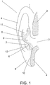
- FIG. 1 shows a frontal section of a typical pinna 1 of a human.
- the section plane intersects tissue and cartilaginous parts of the pinna 1 as indicated by the shaded areas 2 as well as the ear canal of which only the entrance 3 is shown.
- the helix 4 and the earlobe 5 together form an outer rim of the pinna 1.
- the antitragus 6 forms an upwardly and forwardly directed ridge, the crest of which is indicated by the dashed line 7.
- the shaded area 8 indicates portions of the concha 9 that are typically obscured by other features of the pinna 1, such as e.g. the antitragus 6, when the ear 1 is viewed from the side, i.e. in a lateral view.
- the two vertical dotted lines 10, 11 indicate respectively the front end and the rear end of the antitragus crest 7.
- the antitragus crest 7 outwardly delimits an inwardly inclined surface area 12 of the antitragus 6.
- FIG. 2-6 show features of two different monaural wireless headsets, which, however, have many features in common. They both illustrate how a monaural wireless headset with an improved wearing comfort may be provided without compromising secure holding or other relevant specifications, such as e.g. the sound quality, the ease of use, the operating time (battery charging interval) and/or the possibility to manufacture large quantities of headsets without having to customize or fit the headsets individually for each user at the factory.
- a monaural wireless headset with an improved wearing comfort may be provided without compromising secure holding or other relevant specifications, such as e.g. the sound quality, the ease of use, the operating time (battery charging interval) and/or the possibility to manufacture large quantities of headsets without having to customize or fit the headsets individually for each user at the factory.
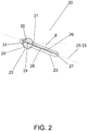
- FIG. 2 shows a lateral view of a monaural wireless headset 20 with an outwards facing wall 34 (see FIG. 3 ) of the housing 21 removed.
- the monaural wireless headset 20 is shown as viewed from the side facing outwards when the headset 20 is worn and with an orientation substantially corresponding to the orientation in an intended wearing position (see FIG. 4 ) at the user's righthand ear 1.
- the housing 21 comprises a main body 22 and a microphone boom 23.
- the main body 22 is substantially cylindrical with a substantially laterally oriented cylinder axis 24, and the microphone boom 23 extends across the axially outer end of the main body 22 forwards towards the user's mouth along a boom axis 25 with an angle ⁇ (see FIG.
- the general design of the housing 21 is based primarily on two ideal design elements, namely a cylinder defining the substantial shape of the main body 22 and a rod defining the substantial shape of the microphone boom 23.
- the ideal design elements 22, 23 intersect and thus share a common volume 30 within the housing 21. Boundaries of the common volume 30 are indicated by dashed lines in FIGs. 2 and 3c .
- a circuit board 26 is arranged within the microphone boom 23 and extends through a length portion of the microphone boom 23 and the common volume 30 of the ideal design elements 22, 23.
- a microphone 27 is arranged near the mouth end or front end of the circuit board 26 within the microphone boom 23.
- a wireless transceiver 28 is arranged at the circuit board 26 along a major portion thereof.
- the main body 22 comprises a cylindrically wound lithium-ion rechargeable battery 29.
- the rechargeable battery 29 has a cylindrical section with a cylinder axis substantially equal to the cylinder axis 24 of the main body 22.
- the rechargeable battery 29 further has an outer fin-shaped electrode 31 at its axially outer end and an inner fin-shaped electrode 32 (see FIG. 3c ) at its axially inner end.
- the outer electrode 31 extends mainly in a device-median plane 33 parallel to the cylinder axis 24 and parallel to the boom axis 25.
- the generally circular cross section of the axially inner portion of the main body 22 allows the user to easily rotate the housing 21 about the cylinder axis 24 and thus adjust the downwards angle ⁇ of the microphone boom 23 to fit personal preferences without causing any discomfort.
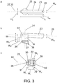
- FIGs. 3a, 3b and 3c show orthogonal views of the monaural wireless headset 20.
- FIG. 3a shows the monaural wireless headset 20 from the same side as in FIG. 2 , however with the outwards facing wall 34 of the housing 21 in place and with the boom axis 25, and thus also the device-median plane 33, oriented horizontally.
- the outwards facing wall 34 has a microphone inlet 35 near its mouth end that acoustically connects the environment with a sound inlet of the microphone 27 such that a voice signal from the user may reach the microphone 27 when the monaural wireless headset 20 is worn in the wearing position.
- the main body 22 has a diameter - and thus a height H b - of about 15 mm, while the microphone boom 23 has a height H m of about 7 mm.
- the microphone boom 23 has a total length L of about 58 mm and extends forwards from the main body 22 by a boom length L m of about 38 mm.
- FIG. 3b shows a bottom view of the monaural wireless headset 20 perpendicular to the device-median plane 33.
- the cylinder surface of the main body 22 has an annular groove 36 for detachably receiving a corresponding rim of a resilient earbud 37.
- FIG. 3b shows a section of the earbud 37 in the device-median plane 33.
- the earbud 37 has a channel 38 that acoustically connects a sound outlet of a speaker driver 39 (see FIG. 3c ) with the environment such that a sound signal provided by the speaker driver 39 may reach the user's ear canal 3 when the monaural wireless headset 20 is worn in the wearing position.
- the circular cross section of the axially inner portion of the main body 22 and the annular groove 36 allow the user to manually rotate the earbud 37 about the cylinder axis 24 of the main body 22 and thus adjust the fit.
- the earbud 37 may further comprise an elastic support member (not shown) extending approximately perpendicularly to the battery axis 24 opposite the sound channel 38 and having a shape, like e.g. a hook, a ring or a fin, and an elasticity allowing it to apply a pressure onto a portion of the concha 9, preferably onto a rear portion of the concha 9, such as e.g. a portion within the shaded area 8 in FIG. 1 , in order to support or maintain the monaural wireless headset 20 in the wearing position.
- the main body 22 has a width W b of about 18 mm, while the microphone boom 23 has a width W m of about 10 mm.
- the inwards facing surface of the microphone boom 23 has an outwards offset W o of about 12 mm from the axially inner end of the main body 22, such that the monaural wireless headset 20 - without the earbud 37 - has a total width W of about 22 mm.
- FIG. 3c shows a front section view of the monaural wireless headset 20 along the boom axis 25.
- Dashed lines indicate boundaries of the common volume 30 shared by the ideal design elements 22, 23 of the housing 21.
- the section plane intersects the main body 22, the microphone boom 23, the circuit board 26, the rechargeable battery 29, the common volume 30, the outer electrode 31, the inner electrode 32 and the speaker driver 39.
- the speaker driver 39 is arranged coaxially with the main body 22 and thus with the rechargeable battery 29.
- the inner electrode 32 extends mainly in a plane perpendicular to the cylinder axis 24, which allows the cylindrical section of the rechargeable battery 29 and the speaker driver 39 to be arranged with a minimum distance W s to each other of about 1 mm.
- the cylindrical section of the rechargeable battery 29 has a width, i.e. an axial length, W r of about 12 mm, and the speaker driver 39 has a width W d of about 3 mm.
- W r an axial length
- W d width
- the axially inner end or surface area of the rechargeable battery 29 is located about 4 mm outwards from the axially inner end or surface area of the speaker driver 39.
- a length section of the circuit board 26 extending across the axially outer end of the rechargeable battery 29 has a width W c of about 3 mm.
- One or more length sections of the circuit board 26 located further towards the mouth end of the microphone boom 23 have a larger width of about 6-8 mm. The latter is possible because the rechargeable battery 29 does not limit the available space for such sections.
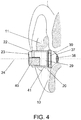
- FIG. 4 shows a frontal section of the pinna 1 of FIG. 1 with the monaural wireless headset 20 of FIGs. 2 and 3 arranged in its intended wearing position.
- the section plane is the same as in FIG. 1 . Since the shape of the pinna 1 is individual for each user, the actual wearing position may deviate from the shown intended wearing position.
- the main body 22 lies entirely behind the section plane with its cylinder axis 24 oriented horizontally.
- the outlines of the rechargeable battery 29 and the speaker driver 39 are indicated by respective dashed rectangles.
- the section plane intersects the microphone boom 23 where it protrudes forwards towards the user's mouth as indicated by the shaded area 40.
- the microphone boom 23 extends forwards with a downwards angle ⁇ , and - as may be deducted from the figure - its outwards offset W o allows it to extend past the tragus (not shown) and thus extend outside the pinna 1 without causing discomfort to the user.
- the earbud 37 is shown as a transparent body. Its channel 38 leads sound output from the speaker driver 39 forwards and inwards into the opening 3 of the ear canal.
- a support surface 41 of the main body 22 abuts a portion of the antitragus 6, in particular a portion of the crest 7, when the monaural wireless headset 20 is in the wearing position.
- the support surface 41 extends mainly across lower and rear portions of the cylinder surface near the axially inner end of the main body 22. The exact position and extension of the support surface 41 for a particular user depends on the actual shape of the user's pinna 1 and on the user's choice of downwards angle ⁇ of the microphone boom 23.
- the general design of the monaural wireless headset 20, the dimensions of the housing 21 as well as the shown arrangement of the rechargeable battery 29 and the speaker driver 39 within the main body 22 allows most adult users to arrange the monaural wireless headset 20 such in their ear 1 that the speaker driver 39 and a portion of the rechargeable battery 29 reside on the inside of the crest 7 of the antitragus 6, i.e. further towards the sagittal plane than the crest 7. Since the rechargeable battery 29 and the speaker driver 39 are relatively heavy components of the monaural wireless headset 20, the shown headset configuration and wearing position provide for an improved balance of the housing 21 such that for most adult users, the earbud 37 and the support surface 41 will suffice to securely hold the monaural wireless headset 20 in place during use. Furthermore, the resilient earbud 37 as well as the smooth support surface 41 make the monaural wireless headset 20 comfortable to wear.
- the monaural wireless headset 20 may further comprise a detachable ear hook (not shown) having an annular fastening means adapted to surround a cylindrical section of the main body 22 and dimensioned to provide a frictional fit between the ear hook and the main body 22, such that the ear hook is rotatable about the cylinder axis 24 of the main body 22, such that a user can attach the ear hook to the monaural wireless headset 20 by sliding it onto the cylinder surface of the main body 22 from the axially inner end of the main body 22 and such that the user can detach it by the corresponding reversed action.
- a detachable ear hook (not shown) having an annular fastening means adapted to surround a cylindrical section of the main body 22 and dimensioned to provide a frictional fit between the ear hook and the main body 22, such that the ear hook is rotatable about the cylinder axis 24 of the main body 22, such that a user can attach the ear hook to the monaural wireless headset 20 by sliding it
- the annular fastening means may preferably be elastic and have a radially inner surface that has a substantially circular cylindrical section and has e.g. three, four or five axially oriented and evenly distributed ridges, such that when the ear hook is attached to the main body 22, the ridges abut the main body 22 and cause a predefined elastic deformation of the annular fastening means, which thereby exerts a radially inwards directed force with a predefined magnitude on the cylinder surface of the main body 22.
- the ridges thus provide an improved frictional fit.
- FIG. 5 shows a front section of a monaural wireless headset 20 with a housing 21 comprising a main body 22 and a microphone boom 23.
- the main body 22 has a battery compartment 50 mainly comprising a rechargeable battery 29 and a speaker compartment 51 mainly comprising a speaker driver 39.
- the rechargeable battery 29 is a button-cell lithium-ion battery with a cylindrical cross section and a corresponding battery axis 24.
- the battery compartment 50 has a cylindrical cross section and is arranged coaxially with the battery axis 24.
- the battery axis 24 lies behind the section plane.
- portions 52 of the battery compartment 50 thus obscure portions of the rechargeable battery 29, the outline of which is indicated by the dashed rectangle 53.
- the battery compartment 50 has a diameter or height H b of about 17 mm and a width W b along the battery axis 24 of about 8 mm.
- the speaker driver 39 and the speaker compartment 51 have cylindrical cross sections and are arranged coaxially with a common speaker axis 54 that lies horizontally in the section plane.
- the speaker compartment 51 Near its axially inner end, the speaker compartment 51 has an annular groove 36 for detachably receiving a corresponding rim of a resilient earbud 37.
- the earbud 37 has a channel 38 that acoustically connects a sound outlet of the speaker driver 39 with the environment such that a sound signal provided by the speaker driver 39 may reach the user's ear canal 3 when the monaural wireless headset 20 is worn in a wearing position (see FIG.
- the circular cross section of the axially inner portion of the speaker compartment 50 and the annular groove 36 allow the user to manually rotate the earbud 37 about the speaker axis 54 to adjust the fit of asymmetric earbuds 37.
- the speaker compartment 51 has a diameter or height H e of about 8 mm and a width W e along the speaker axis 54 of about 8 mm allowing it to be at least partly inserted into the ear canal 3.
- the battery axis 24 is inclined by an angle ⁇ of about 20° with respect to the speaker axis 54, such that the battery compartment 50 appears to be tilted outwards by the same angle ⁇ .
- the microphone boom 23 is connected to the main body 22 at the axially outer portion of the battery compartment 50 and extends forwards with a downwards angle ⁇ (similarly as shown in FIG. 2 ).
- the section plane intersects the microphone boom 23 where it extends forwards on the outer side of the rechargeable battery 29 as indicated by the shaded area 40.
- the microphone boom 23 has a height H m of about 6 mm and a width W m of about 6 mm.
- the microphone boom 23 is mechanically connected to an upper portion of the battery compartment 50 in order to have the connection located further outwards.
- the microphone boom 23 extends forwards and downwards from the main body 22 by a boom length L m (see FIG. 3a ) of about 34 mm.
- a circuit board 26 is arranged within the microphone boom 23 and extends through a length portion of the microphone boom 23; a microphone 27 is arranged near the mouth end of the circuit board 26 within the microphone boom 23; a wireless transceiver 28 is arranged at the circuit board 26 along a major portion thereof; and an outwards facing wall 34 of the microphone boom 23 has a microphone inlet 35 near its mouth end that acoustically connects the environment with a sound inlet of the microphone 27 such that a voice signal from the user may reach the microphone 27 when the monaural wireless headset 20 is worn in the wearing position.
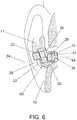
- FIG. 6 shows a frontal section of the pinna 1 of FIG. 1 with the monaural wireless headset 20 of FIG. 5 arranged in its intended wearing position.
- the section plane is the same as in FIG. 1 and in FIG. 5 . Since the shape of the pinna 1 is individual for each user, the actual wearing position may deviate from the shown intended wearing position.
- the monaural wireless headset 20 is shown with the earbud 37 inserted into the ear canal 3 such that the earbud channel 38 leads sound output from the speaker driver 39 directly into the ear canal 3.
- the speaker axis 54 is oriented approximately horizontally with a slight upwards inclination in the inwards direction and is thus substantially coaxially aligned with the ear canal 3.
- a support surface 60 of the main body 22 abuts an inwardly inclined surface portion 12 of the antitragus 6 when the monaural wireless headset 20 is in the wearing position. Thus, a portion of the main body 22 laterally overlaps the antitragus 6 on the inwards side thereof.
- the support surface 60 extends mainly across lower and rear portions of the axially outer surface of the battery compartment 50. The exact position and extension of the support surface 60 for a particular user depends on the actual shape of the user's pinna 1 and on the user's choice of downwards angle ⁇ of the microphone boom 23.
- the general design of the monaural wireless headset 20, the dimensions of the housing 21 as well as the shown arrangement of the rechargeable battery 29 and the speaker driver 39 within the main body 22 allows most adult users to arrange the monaural wireless headset 20 such in their ear 1 that the speaker driver 39 and a major portion of the rechargeable battery 29 reside on the inside of the crest 7 of the antitragus 6. Since the rechargeable battery 29 and the speaker driver 39 are relatively heavy components of the monaural wireless headset 20, the shown headset configuration and wearing position provide for an improved balance of the housing 21 such that for most adult users, the earbud 37 and the support surface 60 will suffice to securely hold the monaural wireless headset 20 in place during use. Furthermore, the resilient earbud 37 as well as the smooth support surface 60 make the monaural wireless headset 20 comfortable to wear. Preferably, a portion of the rechargeable battery 29 laterally overlaps the antitragus 6 on the inwards side thereof.
- the microphone boom 23 extends linearly forwards and downwards towards the user's mouth when the monaural wireless headset 20 is in the wearing position - similarly to the microphone boom 23 shown in FIG. 2 .
- the monaural wireless headset 20 of FIGs. 5 and 6 has the mechanical connection between the microphone boom 23 and the main body 22 located further inwards. For some users, this may cause the microphone boom 23 to touch the tragus (not shown), which may reduce the wearing comfort.
- the microphone boom 23 may preferably have one or more bends along its length allowing it to circumvent the tragus.
- the microphone boom 23 may have an outwards bend near the main body 22, corresponding to the angle ⁇ (see FIG. 3b ) being larger than 90°, and an inwards bend further forwards to allow the foremost portion of the microphone boom 23 to be approximately aligned with the user's cheek.
- the microphone boom 23 may have an upwards bend about 15 mm from the main body 22 such that the microphone boom 23 may escape the pinna 1 through the tragical notch (not shown) at a relatively steep downwards angle ⁇ (see FIG. 2 ) and continue outside the pinna 1 towards the user's mouth at a less steep angle ⁇ .
- the microphone 27 is adapted to receive a voice signal from the user and provide a microphone signal to the wireless transceiver 28 in dependence on the voice signal when the monaural wireless headset 20 is in the wearing position.
- the wireless transceiver 28 is preferably adapted to transmit a wireless output signal, e.g. to a mobile phone (not shown) through a Bluetooth connection, in dependence on the microphone signal.
- the wireless transceiver 28 is further preferably adapted to receive a wireless input signal, e.g.
- the speaker driver 39 is arranged and adapted to transmit a sound signal into the ear 1 of the user in dependence on the audio output signal when the monaural wireless headset 20 is in the wearing position, and the rechargeable battery 29 is adapted to provide electric power to headset components, such as e.g. the microphone 27, the wireless transceiver 28 and/or the speaker driver 39.
- the monaural wireless headset 20 may preferably further comprise one or more control elements for controlling functions of the headset 20, such as e.g. a power switch for switching the headset 20 on and off, an answer control for accepting incoming phone calls, a reject control for rejecting incoming phone calls, a volume control for changing the sound output level of the speaker driver 39, a mute control for muting the microphone 27, a charging connector and a charging circuit for charging the rechargeable battery 29 and/or one or more status indicators for indicating a device status, such as e.g. a power status, a call status and/or a wireless-connection status of the headset 20.
- a power switch for switching the headset 20 on and off
- an answer control for accepting incoming phone calls
- a reject control for rejecting incoming phone calls
- a volume control for changing the sound output level of the speaker driver 39
- a mute control for muting the microphone 27
- a charging connector and a charging circuit for charging the rechargeable battery 29 and/or one or more status indicators for
- the wireless transceiver 28 may be adapted to connect to an external device, such as e.g. a mobile phone, a personal computer, a headset base station, a media player or the like through a wireless connection, which may e.g. be a Bluetooth connection, a DECT connection, a Wi-Fi connection or any other suitable wireless connection, and the wireless transceiver 28 preferably comprises a corresponding antenna and corresponding encoders and decoders for the wireless signals.
- an external device such as e.g. a mobile phone, a personal computer, a headset base station, a media player or the like
- a wireless connection which may e.g. be a Bluetooth connection, a DECT connection, a Wi-Fi connection or any other suitable wireless connection
- the wireless transceiver 28 preferably comprises a corresponding antenna and corresponding encoders and decoders for the wireless signals.
- the monaural wireless headset 20 may preferably comprise one or more further microphones 27, e.g. comprised by the microphone boom 23 and/or the main body 22, and each being adapted to provide a further microphone signal to the wireless transceiver 28 in dependence on the voice signal and/or an acoustic signal from the environment when the monaural wireless headset 20 is in the wearing position, and the wireless transceiver 28 may further be adapted to transmit the wireless output signal in dependence on the one or more further microphone signals.
- the wireless transceiver 28 may for instance apply any known signal processing to the microphone signals, such as e.g. beamforming, frequency shaping, noise reduction, echo cancelling or the like.
- the monaural wireless headset 20 may for instance comprise a second microphone (not shown) with a sound inlet acoustically connected to a microphone inlet located on the microphone boom 23 about 11 mm further rearwards along the boom axis 25, and the wireless transceiver 28 may combine the microphone signals from the first microphone 27 and the second microphone into a directional microphone signal that emphasizes the user's voice over environment noise in the transmitted wireless output signal.
- the wireless transceiver 28 may alternatively or additionally apply any known signal processing to the received wireless input signal and provide the audio output signal to the speaker driver 39 and/or the wireless output signal in dependence on the processed wireless input signal and/or one or more microphone signals.
- the monaural wireless headset 20 provides an improved compromise between the partly contradictory requirements that are typically applied to such headsets. For instance, achieving a satisfying operating range of a wireless connection to a mobile phone generally requires that the antenna used to wirelessly connect to the mobile phone be located outside the ear canal 3 and preferably also outside the pinna 1. Also, achieving a satisfying quality of the voice signal sent to the mobile phone generally requires that the microphone used to pick up the user's voice be located outside the pinna 1 as well and preferably having an increased sensitivity towards the user's mouth.
- the rechargeable battery 29 is arranged within the main body 22, and at least a portion of the main body 22 is adapted to extend into the concha 9, preferably such that the speaker driver 39 and a portion of the rechargeable battery 29 resides on the inwards side of the crest 7 of the antitragus 6 when the monaural wireless headset 20 is in the wearing position. This allows for an improved weight distribution in the headsets 20.
- the speaker driver 39 preferably has a width W d of less than 5 mm or more preferably less than 4 mm and is preferably arranged such that its inwards facing surface is about flush with the inwards facing surface of the housing 21.
- the inwards facing surface of the speaker driver 39 may be arranged up to about 0.5 mm or up to about 1 mm further inwards than the inwards facing surface of the housing 21, i.e. slightly protruding from the housing 21. In some examples, the inwards facing surface of the speaker driver 39 may be arranged up to about 1 mm or up to about 2 mm further outwards than the inwards facing surface of the housing 21, i.e. slightly recessed with respect to the housing 21. In embodiments similar to the monaural wireless headset 20 of FIGs.
- the inwards facing surface of the speaker driver 39 may preferably be arranged between about 0 mm and about 3 mm further outwards than the inwards facing surface of the housing 21, i.e. slightly recessed.
- the speaker driver 39 may preferably comprise a preferably rigid protective cover, such as a mesh, a grill or a plate with one or more holes, constituting a portion of the inwards facing surface of the speaker driver 39 and allowing sound to pass between the sound outlet of the speaker driver 39 and the environment.
- the portion of the main body 22 that comprises the rechargeable battery 29 preferably has an at least approximately circular cross section and a smooth surface, such that it does not cause discomfort to the user during wearing or during rotating of the main body 22 about the battery axis 24.
- the user may adjust the downwards angle ⁇ of the microphone boom 23 by rotating the monaural wireless headset 20 about the battery axis 24 while the monaural wireless headset 20 is in the wearing position without feeling any discomfort.
- This allows for the main body 22 and the microphone boom 23 to be permanently mechanically connected in a fixed position with respect to each other and thus allows for a mechanically simple and robust structure of the housing 21.
- the main body 22 has a size that allows arranging a relatively large rechargeable battery 29 therein, such that an acceptable operation time can be achieved.
- the cylindrical portion of the main body 22 preferably has a diameter or height H b in the range between 12 mm and 18 mm or even more preferably in the range between 14 mm and 16 mm.
- the circular portion of the main body 22 preferably has a diameter or height H b in the range between 14 mm and 20 mm or even more preferably in the range between 16 mm and 18 mm.
- An improved weight balance may be achieved by arranging the rechargeable battery 29 such that the axially inner end or surface area thereof is less than 5 mm or less than 4 mm from the axially inner end or surface area of the speaker driver 39. This allows not only the entire speaker driver 39 but also a portion of the rechargeable battery 29 to reside on the inside of the antitragus crest 7, thereby providing an improved balance of the monaural wireless headset 20.
- Cylindrically wound batteries such as the rechargeable battery 29 of the monaural wireless headset 20 of FIGs. 2-4 , are typically manufactured with axially opposite fin-shaped electrodes 31, 32 extending in one and the same plane comprising the battery axis. Thus, it may be required to bend the inner electrode 32 during or after manufacturing in order to have it extend mainly in a plane perpendicular to the battery axis 24 as shown in FIG. 3c .
- other embodiments may comprise a rechargeable battery 29 with both fin-shaped electrodes 31, 32 extending in one and the same plane, preferably in the device-median plane 33. This may require the cylindrical portion of the rechargeable battery 29 to be arranged further away from the speaker driver 39 than shown in FIG. 3c .
- the battery axis 24 is inclined with respect to the speaker axis 54, such as e.g. shown in FIG. 5 , which may leave enough space for an inner electrode 32 extending in the device-median plane 33.
- the rechargeable battery 29 of the monaural wireless headset 20 shown in FIGs. 5-6 may alternatively comprise a cylindrically wound battery with both fin-shaped electrodes 31, 32 extending in one and the same plane, preferably parallel to the boom axis 25, and the circuit board 26 may be arranged in parallel with the outer electrode 32 where they overlap, e.g. as shown in FIG. 2 .
- the shapes and/or the dimensions of the monaural wireless headset 20 or of the housing 21 may deviate from the ones disclosed above.
- the total length L of the microphone boom 23 may be in the range between 40 mm and 80 mm, preferably in the range between 50 mm and 70 mm; the boom length L m may be in the range between 20 mm and 60 mm, preferably in the range between 30 mm and 50 mm; the height H m of the microphone boom 23 may be in the range between 3 mm and 9 mm, preferably in the range between 5 mm and 7 mm, and may vary along the length of the microphone boom 23; the width W m of the microphone boom 23 may be in the range between 3 mm and 11 mm, preferably in the range between 5 mm and 9 mm, and may vary along the length of the microphone boom 23; the outwards offset W o of the microphone boom 23 may be in the range between 8 mm and 16 mm, preferably in the range between 10 mm and 12 mm; the width W c of
- each of the headsets 20, and in particular the headset 20 of FIGs. 5-6 may be manufactured in a mirrored version to fit the lefthand ear 1 of a user.
- the microphone boom 23 may be straight, curved and/or provided with one or more bends along its length.
- the monaural wireless headset 20, and in particular the wireless transceiver 28, preferably comprises one or more electronic circuits, such as e.g. analog circuits, digital circuits, microprocessors, signal processors or the like, adapted to perform the described operations as is already known for similar devices of the prior art.
- electronic circuits are preferably implemented as digital circuits operating on digital signals, but any portions hereof may be implemented as analog circuits operating on analog signals.
- any of the electronic circuits may comprise analog-to-digital and/or digital-to-analog converters.
- Functional blocks of digital circuits may be implemented in hardware, firmware or software, or any combination hereof.
- Digital circuits may perform the functions of multiple functional blocks in parallel and/or in interleaved sequence, and functional blocks may distributed in any suitable way among multiple hardware units, such as e.g. signal processors, microcontrollers and other integrated circuits.
Landscapes
- Engineering & Computer Science (AREA)
- Physics & Mathematics (AREA)
- Acoustics & Sound (AREA)
- Signal Processing (AREA)
- Manufacturing & Machinery (AREA)
- Headphones And Earphones (AREA)
- Circuit For Audible Band Transducer (AREA)
Claims (12)
- Casque d'écoute sans fil monaural (20) comprenant un boîtier (21) avec un corps principal (22) et une perche de microphone (23), un microphone (27), un émetteur-récepteur sans fil (28), un pilote de haut-parleur (39) et une batterie rechargeable (29), le casque d'écoute sans fil monaural (20) étant conçu pour être disposé au niveau de l'oreille (1) d'un utilisateur en position d'usure, au moins une partie du corps principal (22) se trouvant du côté intérieur de la crête (7) de l'antitragus de l'oreille (6) et la perche de microphone (23) s'étendant au moins partiellement à l'extérieur de la pinna de l'oreille (1) vers la bouche de l'utilisateur, le microphone (27) étant constitué par la perche de microphone (23) et étant adapté pour recevoir un signal vocal de l'utilisateur et fournir un signal de microphone à l'émetteur-récepteur sans fil (28) en fonction du signal vocal lorsque le casque d'écoute sans fil monaural (20) est en position de port, l'émetteur-récepteur sans fil (28) étant adapté à transmettre un signal de sortie sans fil en fonction du signal du microphone, l'émetteur-récepteur sans fil (28) étant en outre adaptée pour recevoir un signal d'entrée sans fil et fournir un signal de sortie audio au pilote de haut-parleur (39) en fonction du signal d'entrée sans fil, le pilote de haut-parleur (39) étant conçu et adapté pour transmettre un signal sonore dans l'oreille (1) en fonction du signal de sortie audio lorsque le casque d'écoute sans fil monaural (20) est en position de port, et la batterie rechargeable (29) étant conçue pour fournir une alimentation électrique à l'émetteur-récepteur sans fil (28) et au pilote de haut-parleur (39), le pilote de haut-parleur (39) et la batterie rechargeable (29) étant disposés dans le corps principal (22) de telle sorte que le pilote de haut-parleur (39) et au moins une première partie de la batterie rechargeable (29) résident sur le côté intérieur de la crête (7) de l'antitragus (6) lorsque le casque d'écoute sans fil monaural (20) est en position de port, et la batterie rechargeable (29) ayant une section cylindrique, caractérisé en ce que le pilote de haut-parleur (39) a une section cylindrique avec un axe de cylindre (54) qui est incliné par rapport à l'axe de cylindre (24) de la batterie rechargeable (29).
- Casque d'écoute sans fil monaural selon la revendication 1 et adapté en outre pour être porté sans moyens de portage pour tenir le casque d'écoute dans la position destinée lors de l'usage s'étendant à l'extérieur de la concha de l'oreille (9).
- Casque d'écoute sans fil monaural selon la revendication 1 ou 2, dans lequel le pilote de haut-parleur (39) et la batterie rechargeable (29) sont disposés l'un à côté de l'autre avec une distance minimale l'un de l'autre de moins de 2 mm.
- Casque d'écoute sans fil monaural selon l'une quelconque des revendications précédentes, dans lequel la batterie rechargeable (29) comporte une première électrode (31) s'étendant dans un premier plan (33) parallèle à l'axe du cylindre (24) de la section cylindrique de la batterie rechargeable (29) et dans lequel la perche de microphone (23) s'étend parallèlement au premier plan (33).
- Casque d'écoute sans fil monaural selon la revendication 4, dans lequel l'émetteur-récepteur sans fil (28) est agencé au moins partiellement dans la perche de microphone (23), et dans lequel l'émetteur-récepteur sans fil (28) et la première électrode (31) se chevauchent dans une direction orthogonale au premier plan (33).
- Casque d'écoute sans fil monaural selon l'une quelconque des revendications précédentes, dans lequel le corps principal (22) a une surface de support (41) adaptée pour buter contre une partie de la crête (7) de l'antitragus (6) lorsque le casque d'écoute monaural sans fil (20) est en position de port.
- Casque d'écoute sans fil monaural selon l'une quelconque des revendications précédentes, dans lequel le corps principal (22) a une surface de support (60) adaptée pour buter contre une surface inclinée vers l'intérieur (12) de l'antitragus (7) lorsque le casque d'écoute monaural sans fil (20) est dans la position de port.
- Casque d'écoute sans fil monaural selon l'une quelconque des revendications précédentes, dans lequel l'extrémité ou surface superficielle axialement intérieure de la batterie rechargeable (29) est à moins de 5 mm de l'extrémité ou surface superficielle axialement intérieure du pilote de haut-parleur (39).
- Casque d'écoute sans fil monaural selon l'une quelconque des revendications précédentes, dans lequel la partie de la batterie rechargeable (29) comprend au moins 25% du volume de la batterie rechargeable (29).
- Casque d'écoute sans fil monaural selon la revendication 9, dans lequel la partie de la batterie rechargeable (29) comprend au moins 50% du volume de la batterie rechargeable (29).
- Casque d'écoute sans fil monaural selon l'une quelconque des revendications précédentes, dans lequel la partie de la batterie rechargeable (29) comprend au moins 25% de la masse de la batterie rechargeable (29).
- Casque d'écoute sans fil monaural selon la revendication 11, dans lequel la partie de la batterie rechargeable (29) comprend au moins 50% de la masse de la batterie rechargeable (29).
Priority Applications (5)
| Application Number | Priority Date | Filing Date | Title |
|---|---|---|---|
| EP14170947.7A EP2953377B1 (fr) | 2014-06-03 | 2014-06-03 | Casque d'écoute sans fil monophonique |
| US14/724,289 US9491534B2 (en) | 2014-06-03 | 2015-05-28 | Monaural wireless headset |
| CN201510300976.5A CN105307066B (zh) | 2014-06-03 | 2015-06-03 | 单声道无线耳机 |
| US29/538,263 USD801312S1 (en) | 2014-06-03 | 2015-09-02 | Holder for a headset |
| US29/611,871 USD835610S1 (en) | 2014-06-03 | 2017-07-26 | Headset |
Applications Claiming Priority (1)
| Application Number | Priority Date | Filing Date | Title |
|---|---|---|---|
| EP14170947.7A EP2953377B1 (fr) | 2014-06-03 | 2014-06-03 | Casque d'écoute sans fil monophonique |
Publications (2)
| Publication Number | Publication Date |
|---|---|
| EP2953377A1 EP2953377A1 (fr) | 2015-12-09 |
| EP2953377B1 true EP2953377B1 (fr) | 2020-05-06 |
Family
ID=50841679
Family Applications (1)
| Application Number | Title | Priority Date | Filing Date |
|---|---|---|---|
| EP14170947.7A Active EP2953377B1 (fr) | 2014-06-03 | 2014-06-03 | Casque d'écoute sans fil monophonique |
Country Status (3)
| Country | Link |
|---|---|
| US (3) | US9491534B2 (fr) |
| EP (1) | EP2953377B1 (fr) |
| CN (1) | CN105307066B (fr) |
Families Citing this family (58)
| Publication number | Priority date | Publication date | Assignee | Title |
|---|---|---|---|---|
| WO2015164287A1 (fr) | 2014-04-21 | 2015-10-29 | Uqmartyne Management Llc | Écouteur sans fil |
| EP2953377B1 (fr) * | 2014-06-03 | 2020-05-06 | GN Audio A/S | Casque d'écoute sans fil monophonique |
| US9532128B2 (en) | 2014-09-05 | 2016-12-27 | Earin Ab | Charging of wireless earbuds |
| EP3189671B1 (fr) * | 2014-09-05 | 2020-11-11 | Earin AB | Perfectionnements apportés à des écouteurs boutons sans fil et à leur charge |
| US9402120B2 (en) | 2014-09-05 | 2016-07-26 | Epickal AB | Wireless earbuds |
| USD772840S1 (en) * | 2014-12-11 | 2016-11-29 | Epickal AB | Pair of earphones and casing |
| US9558731B2 (en) * | 2015-06-15 | 2017-01-31 | Blackberry Limited | Headphones using multiplexed microphone signals to enable active noise cancellation |
| KR101714442B1 (ko) * | 2015-06-18 | 2017-03-22 | 엘지전자 주식회사 | 휴대용 음향기기 |
| US10856068B2 (en) | 2015-09-16 | 2020-12-01 | Apple Inc. | Earbuds |
| US9699546B2 (en) * | 2015-09-16 | 2017-07-04 | Apple Inc. | Earbuds with biometric sensing |
| USD772204S1 (en) * | 2015-11-03 | 2016-11-22 | Cleer Gear Llc | Wireless earpiece with charging capsule |
| USD789909S1 (en) * | 2016-01-02 | 2017-06-20 | Erato (Cayman) Holdings Co., Ltd. | Earphone |
| TWI608741B (zh) * | 2016-02-19 | 2017-12-11 | 精冠科技股份有限公司 | 耳機、耳機充電裝置及耳機充電電路 |
| WO2017171756A1 (fr) * | 2016-03-30 | 2017-10-05 | Hewlett-Packard Development Company, L.P. | Indicateur conçu pour indiquer un état d'une application d'assistant personnel |
| US10015581B2 (en) * | 2016-06-14 | 2018-07-03 | Bose Corporation | Feedback microphone adaptor for noise canceling headphone |
| USD832240S1 (en) * | 2016-07-07 | 2018-10-30 | Gn Audio A/S | Ear gel for an earphone |
| CN106214337A (zh) * | 2016-08-17 | 2016-12-14 | 徐自升 | 一种人体工学自固定式耳塞 |
| EP3417635A1 (fr) | 2016-09-06 | 2018-12-26 | Apple Inc. | Ensembles écouteur à bouts d'ailette pour ancrage à un utilisateur |
| USD806648S1 (en) * | 2016-11-07 | 2018-01-02 | Sonova Ag | Hearing aid charging unit |
| USD816994S1 (en) * | 2016-11-10 | 2018-05-08 | Harman International Industries, Incorporated | Electronics case |
| EP3324644B1 (fr) * | 2016-11-17 | 2020-11-04 | Oticon A/s | Dispositif auditif sans fil avec stabilisateur entre tragus et anti-tragus |
| CA3046141C (fr) * | 2016-12-09 | 2022-08-16 | T & W Engineering A/S | Dispositif d'oreille generique a electrodes |
| JP1604956S (fr) * | 2017-01-03 | 2018-05-28 | ||
| USD844009S1 (en) * | 2017-01-06 | 2019-03-26 | Samsung Electronics Co., Ltd. | Docking station for portable electronic device |
| USD832264S1 (en) * | 2017-01-06 | 2018-10-30 | Samsung Electronics Co., Ltd. | Docking station for portable electronic device |
| CN106658265B (zh) * | 2017-02-14 | 2023-09-12 | 歌尔股份有限公司 | 降噪耳机以及电子设备 |
| CN107086367B (zh) * | 2017-03-03 | 2020-10-09 | 歌尔科技有限公司 | 一种具有蓝牙天线的电路板和蓝牙设备 |
| US11089409B2 (en) | 2017-07-20 | 2021-08-10 | Sonova Ag | Hearing device, a sound receiving arrangement, a set of parts and a hearing device system |
| USD862420S1 (en) * | 2017-07-25 | 2019-10-08 | Moon Selfie, Inc. | Clip accessory for personal communication device |
| USD856305S1 (en) * | 2017-08-31 | 2019-08-13 | Moon Selfie, Inc. | Clip accessory for personal communication device |
| USD904344S1 (en) * | 2017-10-31 | 2020-12-08 | Sony Corporation | Sound generator |
| KR102574835B1 (ko) * | 2018-03-26 | 2023-09-06 | 소니그룹주식회사 | 음향 출력 장치 |
| USD873705S1 (en) * | 2018-06-15 | 2020-01-28 | Monica Horn | Centerpiece |
| USD875097S1 (en) * | 2018-09-28 | 2020-02-11 | Purple Tambourine Limited | Docking station for a pointing controller |
| US10993054B2 (en) | 2018-11-21 | 2021-04-27 | Starkey Laboratories, Inc. | Wax protection for in-canal hearing device |
| US20200278832A1 (en) * | 2019-02-28 | 2020-09-03 | Qualcomm Incorporated | Voice activation for computing devices |
| USD904023S1 (en) * | 2019-03-26 | 2020-12-08 | Aska Electronics Co., Ltd. | Wireless earphone |
| AU2020296003A1 (en) | 2019-06-17 | 2022-02-03 | Oxiwear, Inc. | Wearable earpiece oxygen monitor |
| USD916291S1 (en) * | 2019-06-17 | 2021-04-13 | Oxiwear, Inc. | Earpiece |
| US11477559B2 (en) * | 2019-07-31 | 2022-10-18 | Advanced Semiconductor Engineering, Inc. | Semiconductor device package and acoustic device having the same |
| US11689839B2 (en) * | 2019-07-31 | 2023-06-27 | Advanced Semiconductor Engineering, Inc. | Semiconductor device package and acoustic device including the same |
| USD948482S1 (en) * | 2019-11-14 | 2022-04-12 | Chunhong Liu | Earphone |
| USD891434S1 (en) | 2019-12-06 | 2020-07-28 | elago CO. LTD | Protective cover skin for electronic device |
| CN210899560U (zh) * | 2019-12-19 | 2020-06-30 | Oppo广东移动通信有限公司 | 耳机 |
| CN113225634B (zh) * | 2020-01-21 | 2024-02-20 | 万魔声学股份有限公司 | 耳机 |
| USD946465S1 (en) * | 2020-02-11 | 2022-03-22 | Att Southern, Inc. | Planter |
| USD890725S1 (en) * | 2020-03-26 | 2020-07-21 | Ming Liu | Wireless earphones with charging case |
| USD1002582S1 (en) | 2020-05-29 | 2023-10-24 | Oxiwear, Inc. | Earpiece and charger case |
| USD921615S1 (en) * | 2020-08-06 | 2021-06-08 | Shen Zhen Ocen Technology Co. Ltd | Earphone |
| USD914650S1 (en) * | 2020-09-17 | 2021-03-30 | Mifo Technology Co., Ltd | Wireless earbuds with charging case |
| USD928126S1 (en) * | 2020-09-28 | 2021-08-17 | Xinying Chen | Wireless earphone |
| USD956720S1 (en) * | 2020-09-30 | 2022-07-05 | Shenzhen Zio Communication Technology Co., Ltd. | Earphone |
| USD957367S1 (en) * | 2020-12-01 | 2022-07-12 | Beijing Edifier Technology Co., Ltd. | Earphone |
| USD1009836S1 (en) * | 2021-02-04 | 2024-01-02 | Realme Mobile Telecommunications (Shenzhen) Co., Ltd. | Earphone |
| CN112788470B (zh) * | 2021-03-01 | 2023-01-06 | 维沃移动通信有限公司 | 耳机及耳机控制方法 |
| USD980194S1 (en) * | 2021-04-14 | 2023-03-07 | Justin Lee | Earphone |
| USD980825S1 (en) * | 2021-06-14 | 2023-03-14 | Navajo Manufacturing Company, Inc. | Earbud |
| CN116980789A (zh) * | 2022-04-22 | 2023-10-31 | 北京小米移动软件有限公司 | 无线耳机、装配方法、电子设备及存储介质 |
Citations (2)
| Publication number | Priority date | Publication date | Assignee | Title |
|---|---|---|---|---|
| US20040107080A1 (en) * | 2001-03-02 | 2004-06-03 | Nikolaj Deichmann | Method for modelling customised earpieces |
| WO2008037747A1 (fr) * | 2006-09-26 | 2008-04-03 | Argard Co Ltd | Casque compact rechargeable et ensemble chargeur correspondant |
Family Cites Families (102)
| Publication number | Priority date | Publication date | Assignee | Title |
|---|---|---|---|---|
| US125003A (en) * | 1872-03-26 | Improvement in epergnes for fruits and flowers | ||
| DE348388C (de) * | 1919-07-25 | 1922-02-07 | Siemens Ag | In den Gehoergang einzufuehrendes Telephon winkelfoermiger Bauart |
| USD244338S (en) * | 1975-07-30 | 1977-05-17 | Yauger Leroy J | Bowl |
| USD260134S (en) * | 1979-10-24 | 1981-08-11 | Riffy Bercu | Garden hose coiling device |
| USD298592S (en) * | 1985-01-31 | 1988-11-22 | N.V. Vereenigde Glasfabrieken (United Glassworks) | Jar |
| US4720857A (en) * | 1985-12-06 | 1988-01-19 | Plantronics, Inc. | Miniaturized headset for two-way voice communication |
| USD316550S (en) * | 1988-05-23 | 1991-04-30 | Sony Corporation | Combined earphone and receiver |
| US4917504A (en) * | 1989-05-05 | 1990-04-17 | Plantronics, Inc. | Communications headset |
| USD337177S (en) * | 1991-01-28 | 1993-07-06 | Goody Products, Inc. | Cosmetic receptacle |
| USD357921S (en) * | 1993-08-31 | 1995-05-02 | Sony Corporation | Earphone with microphone |
| USD382874S (en) * | 1995-10-09 | 1997-08-26 | Akg Akustische U. Kino-Gerate Gesellschaft M.B.H. | Talk-listen device |
| USD383646S (en) * | 1995-12-22 | 1997-09-16 | Dart Industries | Bowl |
| USD380729S (en) * | 1996-02-12 | 1997-07-08 | Motorola, Inc. | Top cover for a battery charger |
| US5809159A (en) * | 1997-11-04 | 1998-09-15 | Lee; Chun-Sheng | Structure of an earpiece clamp |
| USD411166S (en) * | 1997-11-21 | 1999-06-22 | Sanyo Electric Co., Ltd. | Charger |
| AU134738S (en) * | 1997-11-25 | 1998-08-17 | Swatch A G Swatch S A Swatch Ltd | Base unit with answering machine for a telephone |
| US5903133A (en) * | 1998-02-23 | 1999-05-11 | Motorola, Inc. | Vehicular beverage holder and charger |
| US6819762B2 (en) * | 2001-03-16 | 2004-11-16 | Aura Communications, Inc. | In-the-ear headset |
| JP3420756B2 (ja) * | 2001-10-30 | 2003-06-30 | 株式会社テムコジャパン | 通信機器用ハンドセット |
| US6795718B2 (en) * | 2002-02-15 | 2004-09-21 | Youngbo Engineering, Inc. | Headset communication device |
| US6574345B1 (en) * | 2002-03-22 | 2003-06-03 | Kuan-Di Huang | Structure of a wearable and hands free earphone |
| USD480376S1 (en) * | 2002-07-30 | 2003-10-07 | Motorola, Inc. | Accessory for holding communications devices or similar articles |
| US7031485B2 (en) * | 2002-09-17 | 2006-04-18 | Mearrings, Inc. | Ear mounting assembly for electronic component |
| USD482348S1 (en) * | 2002-11-05 | 2003-11-18 | Fellowes, Inc. | Earbud |
| USD485390S1 (en) * | 2002-12-06 | 2004-01-13 | B. Cameron Smith | Combined portable night light and recharging cradle |
| KR100513016B1 (ko) * | 2003-01-09 | 2005-09-05 | 삼성전자주식회사 | 무선 헤드셋 장치 |
| USD487077S1 (en) * | 2003-01-28 | 2004-02-24 | Sony Corporation | Earphone |
| USD496029S1 (en) * | 2003-03-10 | 2004-09-14 | Plantronics, Inc. | Cradle for communications headset |
| US6989744B2 (en) * | 2003-06-13 | 2006-01-24 | Proebsting James R | Infant monitoring system with removable ear insert |
| US20050008147A1 (en) * | 2003-07-10 | 2005-01-13 | Tung-Hsun Lee | Two-purpose wireless hand-free earphone set for use in driving |
| US7149552B2 (en) * | 2003-09-19 | 2006-12-12 | Radeum, Inc. | Wireless headset for communications device |
| US20080273735A1 (en) * | 2004-02-27 | 2008-11-06 | Plantronics, Inc. | Voice tube antenna for wireless headset |
| USD512049S1 (en) * | 2004-06-08 | 2005-11-29 | Cotron Corporation | Earphone |
| USD516025S1 (en) * | 2004-12-21 | 2006-02-28 | Ckq Designs, Inc. | Holder/charging stand for a mobile phone or the like |
| US7379557B2 (en) * | 2004-12-22 | 2008-05-27 | Airdigit Incorporation | Communication headset with auxiliary positioning device |
| USD526641S1 (en) * | 2005-03-09 | 2006-08-15 | Plantronics, Inc. | Charge pocket for communications headset |
| USD530717S1 (en) * | 2005-04-15 | 2006-10-24 | Belkin Corporation | USB hub |
| USD518477S1 (en) * | 2005-06-06 | 2006-04-04 | He-And Technology Co., Ltd. | Bluetooth earphone with a connector |
| US7983433B2 (en) * | 2005-11-08 | 2011-07-19 | Think-A-Move, Ltd. | Earset assembly |
| USD544350S1 (en) * | 2005-12-01 | 2007-06-12 | Access Business Group International Llc | Cosmetic container |
| US7734055B2 (en) * | 2005-12-22 | 2010-06-08 | Microsoft Corporation | User configurable headset for monaural and binaural modes |
| EP1811808B1 (fr) * | 2006-01-19 | 2017-03-22 | Oticon A/S | Fixation d'un dispositif pour conduit auditif |
| USD553122S1 (en) * | 2006-03-03 | 2007-10-16 | Harman International Industries, Incorporated | Audio and docking station for handheld electronic device |
| USD551216S1 (en) * | 2006-03-29 | 2007-09-18 | He-And Technology Co., Ltd. | Bluetooth earphone and adapter |
| USD554990S1 (en) * | 2006-05-11 | 2007-11-13 | Sorematic S.A. | Packaging or container for food products such as confectionery products |
| US7502484B2 (en) * | 2006-06-14 | 2009-03-10 | Think-A-Move, Ltd. | Ear sensor assembly for speech processing |
| US8249287B2 (en) * | 2010-08-16 | 2012-08-21 | Bose Corporation | Earpiece positioning and retaining |
| USD555152S1 (en) * | 2006-07-26 | 2007-11-13 | Plantronics, Inc. | Communications headset |
| CN101115317A (zh) * | 2006-07-28 | 2008-01-30 | 鸿富锦精密工业(深圳)有限公司 | 耳机阻抗可调节的耳机 |
| USD554109S1 (en) * | 2006-08-17 | 2007-10-30 | Microsoft Corporation | Pair of earphones |
| KR100842607B1 (ko) * | 2006-10-13 | 2008-07-01 | 삼성전자주식회사 | 헤드 셋 장치의 충전 거치대 및 헤드 셋 장치의 스피커커버 |
| USD575289S1 (en) * | 2006-12-11 | 2008-08-19 | Hon Hai Precision Ind. Co., Ltd. | Dock connector |
| US8059845B2 (en) * | 2007-01-29 | 2011-11-15 | Bryant Joshua R | In ear communications device and stabilizer |
| USD583804S1 (en) * | 2007-01-31 | 2008-12-30 | Southwing, S.L. | Headset |
| TWM316594U (en) * | 2007-02-01 | 2007-08-01 | Lite On Technology Corp | Bluetooth earphone and ear-hook device thereof |
| USD572242S1 (en) * | 2007-02-07 | 2008-07-01 | Cotron Corporation | Earphone |
| US7986803B1 (en) * | 2007-05-10 | 2011-07-26 | Plantronics, Inc. | Ear bud speaker earphone with retainer tab |
| USD589031S1 (en) * | 2007-08-14 | 2009-03-24 | Plantronics, Inc. | Base cradle for a communications headset |
| USD593998S1 (en) * | 2007-08-14 | 2009-06-09 | Plantronics, Inc. | Base cradle for a communications headset |
| USD602008S1 (en) * | 2007-08-14 | 2009-10-13 | Plantronics, Inc. | Base cradle for a communications headset |
| US8218799B2 (en) * | 2007-08-22 | 2012-07-10 | Matthew Stephen Murphy | Non-occluding audio headset positioned in the ear canal |
| USD575269S1 (en) * | 2007-08-24 | 2008-08-19 | Microsoft Corporation | Ear phones |
| USD591722S1 (en) * | 2007-09-07 | 2009-05-05 | Sony Corporation | Earphone |
| USD591721S1 (en) * | 2007-09-07 | 2009-05-05 | Sony Corporation | Earphone |
| US8111861B2 (en) * | 2008-05-19 | 2012-02-07 | Auria Llc | Earbud that secures to the tragus and anti-tragus of the ear |
| USD604273S1 (en) * | 2008-07-11 | 2009-11-17 | Nec Tokin Corporation | Bone conduction earphone |
| USD604272S1 (en) * | 2008-07-31 | 2009-11-17 | Sony Corporation | Earphone |
| USD617778S1 (en) | 2009-02-25 | 2010-06-15 | Gn Netcom A/S | Headset and base |
| USD602917S1 (en) * | 2009-03-25 | 2009-10-27 | Plantronics, Inc. | Base cradle for a communications headset |
| USD604718S1 (en) * | 2009-04-14 | 2009-11-24 | Plantronics, Inc. | Communications headset |
| EP2330829B1 (fr) * | 2009-12-02 | 2012-11-14 | GN Netcom A/S | Casque de communication doté d'une rainure circonférentielle pour le microphone |
| US20110135135A1 (en) * | 2009-12-03 | 2011-06-09 | Jan Hofman | Wireless Headsets Having an Intuitive Man Machine Interface and Related Systems and Methods |
| USD641008S1 (en) * | 2010-01-04 | 2011-07-05 | Monster Cable Products, Inc. | Pair of in-ear headphones |
| US8654987B2 (en) * | 2010-01-11 | 2014-02-18 | Dennis Palma | Audio player headset earhook apparatus and system thereof |
| US20110244927A1 (en) * | 2010-03-31 | 2011-10-06 | Nokia Corporation | Apparatus and Method for Wireless Headsets |
| US8401218B2 (en) * | 2010-07-29 | 2013-03-19 | Microsoft Corporation | Adjustable earphone and earphone set |
| US8311253B2 (en) * | 2010-08-16 | 2012-11-13 | Bose Corporation | Earpiece positioning and retaining |
| USD641738S1 (en) * | 2010-09-03 | 2011-07-19 | Nokia Corporation | Headset |
| WO2012047624A1 (fr) * | 2010-09-27 | 2012-04-12 | Intricon Corporation | Structure de prothèse auditive et son système de mise en place |
| USD669888S1 (en) * | 2010-11-23 | 2012-10-30 | Plantronics, Inc. | Base cradle for a communications headset |
| USD657780S1 (en) * | 2010-12-22 | 2012-04-17 | Sony Mobile Communications Ab | Headset |
| US9398362B2 (en) * | 2011-04-05 | 2016-07-19 | Blue-Gear, Inc. | Universal earpiece |
| US8861771B2 (en) * | 2011-06-03 | 2014-10-14 | Alan Stott | Apparatus and system for playing audio signals from an audio source |
| USD671531S1 (en) * | 2011-07-26 | 2012-11-27 | Lg Electronics Inc. | Earphone |
| US8737669B2 (en) * | 2011-07-28 | 2014-05-27 | Bose Corporation | Earpiece passive noise attenuating |
| USD666996S1 (en) * | 2011-10-07 | 2012-09-11 | SMS Audio LLC | Earbud head phone |
| USD673531S1 (en) * | 2011-12-02 | 2013-01-01 | Monster, Llc | Headphone |
| US8805452B2 (en) * | 2012-01-25 | 2014-08-12 | Plantronics, Inc. | Conductive ear flange for extending the range of a sensor in a communications device |
| USD688650S1 (en) * | 2012-03-26 | 2013-08-27 | Hon Hai Precision Industry Co., Ltd. | Earphone |
| CA146147S (en) * | 2012-03-28 | 2013-02-06 | Aric Norine | Soap bar |
| USD689043S1 (en) * | 2012-10-10 | 2013-09-03 | Puma North America, Inc. | Earphones |
| USD694182S1 (en) * | 2012-10-25 | 2013-11-26 | Lg Electronics Inc. | Charger for mobile phones |
| USD695721S1 (en) * | 2012-11-14 | 2013-12-17 | Aac Acoustic Technologies (Shenzhen) Co., Ltd. | Earphone |
| USD697050S1 (en) * | 2012-11-14 | 2014-01-07 | Aac Acoustic Technologies (Shenzhen) Co., Ltd. | Headset |
| USD712883S1 (en) | 2013-01-21 | 2014-09-09 | Gn Netcom A/S | Earphone |
| USD730868S1 (en) | 2013-07-03 | 2015-06-02 | Gn Netcom, A/S | Headset |
| US8908899B1 (en) * | 2013-08-29 | 2014-12-09 | Cotron Corporation | Earphone |
| US9380370B2 (en) * | 2013-12-03 | 2016-06-28 | Auria Llc | Earphone and adapter for an earphone |
| USD728533S1 (en) * | 2014-03-31 | 2015-05-05 | Skullcandy, Inc. | Headphone |
| EP2953377B1 (fr) * | 2014-06-03 | 2020-05-06 | GN Audio A/S | Casque d'écoute sans fil monophonique |
| JP1529592S (fr) * | 2014-11-07 | 2015-07-27 | ||
| USD821362S1 (en) * | 2015-09-03 | 2018-06-26 | Harman International Industries, Incorporated | Headset |
-
2014
- 2014-06-03 EP EP14170947.7A patent/EP2953377B1/fr active Active
-
2015
- 2015-05-28 US US14/724,289 patent/US9491534B2/en active Active
- 2015-06-03 CN CN201510300976.5A patent/CN105307066B/zh active Active
- 2015-09-02 US US29/538,263 patent/USD801312S1/en active Active
-
2017
- 2017-07-26 US US29/611,871 patent/USD835610S1/en active Active
Patent Citations (2)
| Publication number | Priority date | Publication date | Assignee | Title |
|---|---|---|---|---|
| US20040107080A1 (en) * | 2001-03-02 | 2004-06-03 | Nikolaj Deichmann | Method for modelling customised earpieces |
| WO2008037747A1 (fr) * | 2006-09-26 | 2008-04-03 | Argard Co Ltd | Casque compact rechargeable et ensemble chargeur correspondant |
Also Published As
| Publication number | Publication date |
|---|---|
| US9491534B2 (en) | 2016-11-08 |
| CN105307066A (zh) | 2016-02-03 |
| CN105307066B (zh) | 2019-10-11 |
| US20150350762A1 (en) | 2015-12-03 |
| EP2953377A1 (fr) | 2015-12-09 |
| USD835610S1 (en) | 2018-12-11 |
| USD801312S1 (en) | 2017-10-31 |
Similar Documents
| Publication | Publication Date | Title |
|---|---|---|
| EP2953377B1 (fr) | Casque d'écoute sans fil monophonique | |
| US7123737B2 (en) | Ear clasp headset | |
| US6810987B1 (en) | Earbud headset | |
| EP3056018B1 (fr) | Dispositif écouteur à senseur optique | |
| EP2441238B1 (fr) | Système d'écouteur qui comprend un écouteur et un dispositif de retenue portatif | |
| US7680267B2 (en) | Headset with a retractable speaker portion | |
| US8005252B2 (en) | Personal communications earpiece | |
| WO2018079576A1 (fr) | Casque à conduction osseuse | |
| US8411890B2 (en) | Hearing aid | |
| WO2007022634A1 (fr) | Casque d'ecoute sans fil lateral | |
| CN212211366U (zh) | 一种骨传导耳机 | |
| EP2668792A1 (fr) | Aide auditive | |
| EP3324644B1 (fr) | Dispositif auditif sans fil avec stabilisateur entre tragus et anti-tragus | |
| US8611580B2 (en) | Cheek stabilizer for audio headset | |
| US20170325036A1 (en) | Hearing device | |
| CN106658265B (zh) | 降噪耳机以及电子设备 | |
| CN210868110U (zh) | 一种耳塞式骨传导耳机 | |
| EP3041257A1 (fr) | Casque d'écoute sans fil monophonique avec capteur tactile | |
| US20230091575A1 (en) | Audio device with wingtip anchor | |
| CN109644301B (zh) | 声音输出装置 | |
| US20090111527A1 (en) | Adhesive mounted communication device | |
| US20160182699A1 (en) | Multifunction Stylus | |
| EP3576424B1 (fr) | Système comprenant une paire de dispositifs de sortie sonore | |
| EP3068356B1 (fr) | Écouteur | |
| CN215818560U (zh) | 降噪型入耳式蓝牙耳机 |
Legal Events
| Date | Code | Title | Description |
|---|---|---|---|
| PUAI | Public reference made under article 153(3) epc to a published international application that has entered the european phase |
Free format text: ORIGINAL CODE: 0009012 |
|
| AK | Designated contracting states |
Kind code of ref document: A1 Designated state(s): AL AT BE BG CH CY CZ DE DK EE ES FI FR GB GR HR HU IE IS IT LI LT LU LV MC MK MT NL NO PL PT RO RS SE SI SK SM TR |
|
| AX | Request for extension of the european patent |
Extension state: BA ME |
|
| 17P | Request for examination filed |
Effective date: 20160606 |
|
| RBV | Designated contracting states (corrected) |
Designated state(s): AL AT BE BG CH CY CZ DE DK EE ES FI FR GB GR HR HU IE IS IT LI LT LU LV MC MK MT NL NO PL PT RO RS SE SI SK SM TR |
|
| STAA | Information on the status of an ep patent application or granted ep patent |
Free format text: STATUS: EXAMINATION IS IN PROGRESS |
|
| 17Q | First examination report despatched |
Effective date: 20180913 |
|
| GRAP | Despatch of communication of intention to grant a patent |
Free format text: ORIGINAL CODE: EPIDOSNIGR1 |
|
| STAA | Information on the status of an ep patent application or granted ep patent |
Free format text: STATUS: GRANT OF PATENT IS INTENDED |
|
| INTG | Intention to grant announced |
Effective date: 20190726 |
|
| GRAJ | Information related to disapproval of communication of intention to grant by the applicant or resumption of examination proceedings by the epo deleted |
Free format text: ORIGINAL CODE: EPIDOSDIGR1 |
|
| GRAL | Information related to payment of fee for publishing/printing deleted |
Free format text: ORIGINAL CODE: EPIDOSDIGR3 |
|
| GRAS | Grant fee paid |
Free format text: ORIGINAL CODE: EPIDOSNIGR3 |
|
| STAA | Information on the status of an ep patent application or granted ep patent |
Free format text: STATUS: EXAMINATION IS IN PROGRESS |
|
| GRAP | Despatch of communication of intention to grant a patent |
Free format text: ORIGINAL CODE: EPIDOSNIGR1 |
|
| STAA | Information on the status of an ep patent application or granted ep patent |
Free format text: STATUS: GRANT OF PATENT IS INTENDED |
|
| RAP1 | Party data changed (applicant data changed or rights of an application transferred) |
Owner name: GN AUDIO A/S |
|
| INTC | Intention to grant announced (deleted) | ||
| INTG | Intention to grant announced |
Effective date: 20191125 |
|
| GRAA | (expected) grant |
Free format text: ORIGINAL CODE: 0009210 |
|
| STAA | Information on the status of an ep patent application or granted ep patent |
Free format text: STATUS: THE PATENT HAS BEEN GRANTED |
|
| AK | Designated contracting states |
Kind code of ref document: B1 Designated state(s): AL AT BE BG CH CY CZ DE DK EE ES FI FR GB GR HR HU IE IS IT LI LT LU LV MC MK MT NL NO PL PT RO RS SE SI SK SM TR |
|
| REG | Reference to a national code |
Ref country code: GB Ref legal event code: FG4D |
|
| REG | Reference to a national code |
Ref country code: CH Ref legal event code: EP Ref country code: AT Ref legal event code: REF Ref document number: 1268759 Country of ref document: AT Kind code of ref document: T Effective date: 20200515 |
|
| REG | Reference to a national code |
Ref country code: DE Ref legal event code: R096 Ref document number: 602014064842 Country of ref document: DE |
|
| REG | Reference to a national code |
Ref country code: IE Ref legal event code: FG4D |
|
| REG | Reference to a national code |
Ref country code: LT Ref legal event code: MG4D |
|
| REG | Reference to a national code |
Ref country code: NL Ref legal event code: MP Effective date: 20200506 |
|
| PG25 | Lapsed in a contracting state [announced via postgrant information from national office to epo] |
Ref country code: NO Free format text: LAPSE BECAUSE OF FAILURE TO SUBMIT A TRANSLATION OF THE DESCRIPTION OR TO PAY THE FEE WITHIN THE PRESCRIBED TIME-LIMIT Effective date: 20200806 Ref country code: LT Free format text: LAPSE BECAUSE OF FAILURE TO SUBMIT A TRANSLATION OF THE DESCRIPTION OR TO PAY THE FEE WITHIN THE PRESCRIBED TIME-LIMIT Effective date: 20200506 Ref country code: FI Free format text: LAPSE BECAUSE OF FAILURE TO SUBMIT A TRANSLATION OF THE DESCRIPTION OR TO PAY THE FEE WITHIN THE PRESCRIBED TIME-LIMIT Effective date: 20200506 Ref country code: PT Free format text: LAPSE BECAUSE OF FAILURE TO SUBMIT A TRANSLATION OF THE DESCRIPTION OR TO PAY THE FEE WITHIN THE PRESCRIBED TIME-LIMIT Effective date: 20200907 Ref country code: IS Free format text: LAPSE BECAUSE OF FAILURE TO SUBMIT A TRANSLATION OF THE DESCRIPTION OR TO PAY THE FEE WITHIN THE PRESCRIBED TIME-LIMIT Effective date: 20200906 Ref country code: SE Free format text: LAPSE BECAUSE OF FAILURE TO SUBMIT A TRANSLATION OF THE DESCRIPTION OR TO PAY THE FEE WITHIN THE PRESCRIBED TIME-LIMIT Effective date: 20200506 Ref country code: GR Free format text: LAPSE BECAUSE OF FAILURE TO SUBMIT A TRANSLATION OF THE DESCRIPTION OR TO PAY THE FEE WITHIN THE PRESCRIBED TIME-LIMIT Effective date: 20200807 |
|
| PG25 | Lapsed in a contracting state [announced via postgrant information from national office to epo] |
Ref country code: RS Free format text: LAPSE BECAUSE OF FAILURE TO SUBMIT A TRANSLATION OF THE DESCRIPTION OR TO PAY THE FEE WITHIN THE PRESCRIBED TIME-LIMIT Effective date: 20200506 Ref country code: BG Free format text: LAPSE BECAUSE OF FAILURE TO SUBMIT A TRANSLATION OF THE DESCRIPTION OR TO PAY THE FEE WITHIN THE PRESCRIBED TIME-LIMIT Effective date: 20200806 Ref country code: LV Free format text: LAPSE BECAUSE OF FAILURE TO SUBMIT A TRANSLATION OF THE DESCRIPTION OR TO PAY THE FEE WITHIN THE PRESCRIBED TIME-LIMIT Effective date: 20200506 Ref country code: HR Free format text: LAPSE BECAUSE OF FAILURE TO SUBMIT A TRANSLATION OF THE DESCRIPTION OR TO PAY THE FEE WITHIN THE PRESCRIBED TIME-LIMIT Effective date: 20200506 |
|
| REG | Reference to a national code |
Ref country code: AT Ref legal event code: MK05 Ref document number: 1268759 Country of ref document: AT Kind code of ref document: T Effective date: 20200506 |
|
| PG25 | Lapsed in a contracting state [announced via postgrant information from national office to epo] |
Ref country code: NL Free format text: LAPSE BECAUSE OF FAILURE TO SUBMIT A TRANSLATION OF THE DESCRIPTION OR TO PAY THE FEE WITHIN THE PRESCRIBED TIME-LIMIT Effective date: 20200506 Ref country code: AL Free format text: LAPSE BECAUSE OF FAILURE TO SUBMIT A TRANSLATION OF THE DESCRIPTION OR TO PAY THE FEE WITHIN THE PRESCRIBED TIME-LIMIT Effective date: 20200506 |
|
| PG25 | Lapsed in a contracting state [announced via postgrant information from national office to epo] |
Ref country code: ES Free format text: LAPSE BECAUSE OF FAILURE TO SUBMIT A TRANSLATION OF THE DESCRIPTION OR TO PAY THE FEE WITHIN THE PRESCRIBED TIME-LIMIT Effective date: 20200506 Ref country code: AT Free format text: LAPSE BECAUSE OF FAILURE TO SUBMIT A TRANSLATION OF THE DESCRIPTION OR TO PAY THE FEE WITHIN THE PRESCRIBED TIME-LIMIT Effective date: 20200506 Ref country code: RO Free format text: LAPSE BECAUSE OF FAILURE TO SUBMIT A TRANSLATION OF THE DESCRIPTION OR TO PAY THE FEE WITHIN THE PRESCRIBED TIME-LIMIT Effective date: 20200506 Ref country code: IT Free format text: LAPSE BECAUSE OF FAILURE TO SUBMIT A TRANSLATION OF THE DESCRIPTION OR TO PAY THE FEE WITHIN THE PRESCRIBED TIME-LIMIT Effective date: 20200506 Ref country code: CZ Free format text: LAPSE BECAUSE OF FAILURE TO SUBMIT A TRANSLATION OF THE DESCRIPTION OR TO PAY THE FEE WITHIN THE PRESCRIBED TIME-LIMIT Effective date: 20200506 Ref country code: EE Free format text: LAPSE BECAUSE OF FAILURE TO SUBMIT A TRANSLATION OF THE DESCRIPTION OR TO PAY THE FEE WITHIN THE PRESCRIBED TIME-LIMIT Effective date: 20200506 Ref country code: SM Free format text: LAPSE BECAUSE OF FAILURE TO SUBMIT A TRANSLATION OF THE DESCRIPTION OR TO PAY THE FEE WITHIN THE PRESCRIBED TIME-LIMIT Effective date: 20200506 Ref country code: DK Free format text: LAPSE BECAUSE OF FAILURE TO SUBMIT A TRANSLATION OF THE DESCRIPTION OR TO PAY THE FEE WITHIN THE PRESCRIBED TIME-LIMIT Effective date: 20200506 |
|
| REG | Reference to a national code |
Ref country code: CH Ref legal event code: PL |
|
| REG | Reference to a national code |
Ref country code: DE Ref legal event code: R097 Ref document number: 602014064842 Country of ref document: DE |
|
| PG25 | Lapsed in a contracting state [announced via postgrant information from national office to epo] |
Ref country code: SK Free format text: LAPSE BECAUSE OF FAILURE TO SUBMIT A TRANSLATION OF THE DESCRIPTION OR TO PAY THE FEE WITHIN THE PRESCRIBED TIME-LIMIT Effective date: 20200506 Ref country code: MC Free format text: LAPSE BECAUSE OF FAILURE TO SUBMIT A TRANSLATION OF THE DESCRIPTION OR TO PAY THE FEE WITHIN THE PRESCRIBED TIME-LIMIT Effective date: 20200506 Ref country code: PL Free format text: LAPSE BECAUSE OF FAILURE TO SUBMIT A TRANSLATION OF THE DESCRIPTION OR TO PAY THE FEE WITHIN THE PRESCRIBED TIME-LIMIT Effective date: 20200506 |
|
| PLBE | No opposition filed within time limit |
Free format text: ORIGINAL CODE: 0009261 |
|
| STAA | Information on the status of an ep patent application or granted ep patent |
Free format text: STATUS: NO OPPOSITION FILED WITHIN TIME LIMIT |
|
| PG25 | Lapsed in a contracting state [announced via postgrant information from national office to epo] |
Ref country code: LU Free format text: LAPSE BECAUSE OF NON-PAYMENT OF DUE FEES Effective date: 20200603 |
|
| 26N | No opposition filed |
Effective date: 20210209 |
|
| REG | Reference to a national code |
Ref country code: BE Ref legal event code: MM Effective date: 20200630 |
|
| PG25 | Lapsed in a contracting state [announced via postgrant information from national office to epo] |
Ref country code: CH Free format text: LAPSE BECAUSE OF NON-PAYMENT OF DUE FEES Effective date: 20200630 Ref country code: IE Free format text: LAPSE BECAUSE OF NON-PAYMENT OF DUE FEES Effective date: 20200603 Ref country code: LI Free format text: LAPSE BECAUSE OF NON-PAYMENT OF DUE FEES Effective date: 20200630 |
|
| PG25 | Lapsed in a contracting state [announced via postgrant information from national office to epo] |
Ref country code: SI Free format text: LAPSE BECAUSE OF FAILURE TO SUBMIT A TRANSLATION OF THE DESCRIPTION OR TO PAY THE FEE WITHIN THE PRESCRIBED TIME-LIMIT Effective date: 20200506 Ref country code: BE Free format text: LAPSE BECAUSE OF NON-PAYMENT OF DUE FEES Effective date: 20200630 |
|
| PG25 | Lapsed in a contracting state [announced via postgrant information from national office to epo] |
Ref country code: TR Free format text: LAPSE BECAUSE OF FAILURE TO SUBMIT A TRANSLATION OF THE DESCRIPTION OR TO PAY THE FEE WITHIN THE PRESCRIBED TIME-LIMIT Effective date: 20200506 Ref country code: MT Free format text: LAPSE BECAUSE OF FAILURE TO SUBMIT A TRANSLATION OF THE DESCRIPTION OR TO PAY THE FEE WITHIN THE PRESCRIBED TIME-LIMIT Effective date: 20200506 Ref country code: CY Free format text: LAPSE BECAUSE OF FAILURE TO SUBMIT A TRANSLATION OF THE DESCRIPTION OR TO PAY THE FEE WITHIN THE PRESCRIBED TIME-LIMIT Effective date: 20200506 |
|
| PG25 | Lapsed in a contracting state [announced via postgrant information from national office to epo] |
Ref country code: MK Free format text: LAPSE BECAUSE OF FAILURE TO SUBMIT A TRANSLATION OF THE DESCRIPTION OR TO PAY THE FEE WITHIN THE PRESCRIBED TIME-LIMIT Effective date: 20200506 |
|
| P01 | Opt-out of the competence of the unified patent court (upc) registered |
Effective date: 20230522 |
|
| PGFP | Annual fee paid to national office [announced via postgrant information from national office to epo] |
Ref country code: FR Payment date: 20230619 Year of fee payment: 10 Ref country code: DE Payment date: 20230621 Year of fee payment: 10 |
|
| PGFP | Annual fee paid to national office [announced via postgrant information from national office to epo] |
Ref country code: GB Payment date: 20230619 Year of fee payment: 10 |