EP2953256A2 - Stromwandler - Google Patents
Stromwandler Download PDFInfo
- Publication number
- EP2953256A2 EP2953256A2 EP15169129.2A EP15169129A EP2953256A2 EP 2953256 A2 EP2953256 A2 EP 2953256A2 EP 15169129 A EP15169129 A EP 15169129A EP 2953256 A2 EP2953256 A2 EP 2953256A2
- Authority
- EP
- European Patent Office
- Prior art keywords
- transistors
- electrically connected
- power converter
- recited
- link
- Prior art date
- Legal status (The legal status is an assumption and is not a legal conclusion. Google has not performed a legal analysis and makes no representation as to the accuracy of the status listed.)
- Granted
Links
Images


Classifications
-
- H—ELECTRICITY
- H02—GENERATION; CONVERSION OR DISTRIBUTION OF ELECTRIC POWER
- H02M—APPARATUS FOR CONVERSION BETWEEN AC AND AC, BETWEEN AC AND DC, OR BETWEEN DC AND DC, AND FOR USE WITH MAINS OR SIMILAR POWER SUPPLY SYSTEMS; CONVERSION OF DC OR AC INPUT POWER INTO SURGE OUTPUT POWER; CONTROL OR REGULATION THEREOF
- H02M7/00—Conversion of ac power input into dc power output; Conversion of dc power input into ac power output
- H02M7/42—Conversion of dc power input into ac power output without possibility of reversal
- H02M7/44—Conversion of dc power input into ac power output without possibility of reversal by static converters
- H02M7/48—Conversion of dc power input into ac power output without possibility of reversal by static converters using discharge tubes with control electrode or semiconductor devices with control electrode
- H02M7/483—Converters with outputs that each can have more than two voltages levels
- H02M7/487—Neutral point clamped inverters
-
- B—PERFORMING OPERATIONS; TRANSPORTING
- B60—VEHICLES IN GENERAL
- B60L—PROPULSION OF ELECTRICALLY-PROPELLED VEHICLES; SUPPLYING ELECTRIC POWER FOR AUXILIARY EQUIPMENT OF ELECTRICALLY-PROPELLED VEHICLES; ELECTRODYNAMIC BRAKE SYSTEMS FOR VEHICLES IN GENERAL; MAGNETIC SUSPENSION OR LEVITATION FOR VEHICLES; MONITORING OPERATING VARIABLES OF ELECTRICALLY-PROPELLED VEHICLES; ELECTRIC SAFETY DEVICES FOR ELECTRICALLY-PROPELLED VEHICLES
- B60L50/00—Electric propulsion with power supplied within the vehicle
- B60L50/10—Electric propulsion with power supplied within the vehicle using propulsion power supplied by engine-driven generators, e.g. generators driven by combustion engines
- B60L50/13—Electric propulsion with power supplied within the vehicle using propulsion power supplied by engine-driven generators, e.g. generators driven by combustion engines using AC generators and AC motors
-
- B—PERFORMING OPERATIONS; TRANSPORTING
- B60—VEHICLES IN GENERAL
- B60L—PROPULSION OF ELECTRICALLY-PROPELLED VEHICLES; SUPPLYING ELECTRIC POWER FOR AUXILIARY EQUIPMENT OF ELECTRICALLY-PROPELLED VEHICLES; ELECTRODYNAMIC BRAKE SYSTEMS FOR VEHICLES IN GENERAL; MAGNETIC SUSPENSION OR LEVITATION FOR VEHICLES; MONITORING OPERATING VARIABLES OF ELECTRICALLY-PROPELLED VEHICLES; ELECTRIC SAFETY DEVICES FOR ELECTRICALLY-PROPELLED VEHICLES
- B60L50/00—Electric propulsion with power supplied within the vehicle
- B60L50/10—Electric propulsion with power supplied within the vehicle using propulsion power supplied by engine-driven generators, e.g. generators driven by combustion engines
- B60L50/15—Electric propulsion with power supplied within the vehicle using propulsion power supplied by engine-driven generators, e.g. generators driven by combustion engines with additional electric power supply
-
- H—ELECTRICITY
- H02—GENERATION; CONVERSION OR DISTRIBUTION OF ELECTRIC POWER
- H02M—APPARATUS FOR CONVERSION BETWEEN AC AND AC, BETWEEN AC AND DC, OR BETWEEN DC AND DC, AND FOR USE WITH MAINS OR SIMILAR POWER SUPPLY SYSTEMS; CONVERSION OF DC OR AC INPUT POWER INTO SURGE OUTPUT POWER; CONTROL OR REGULATION THEREOF
- H02M7/00—Conversion of ac power input into dc power output; Conversion of dc power input into ac power output
- H02M7/42—Conversion of dc power input into ac power output without possibility of reversal
- H02M7/44—Conversion of dc power input into ac power output without possibility of reversal by static converters
- H02M7/48—Conversion of dc power input into ac power output without possibility of reversal by static converters using discharge tubes with control electrode or semiconductor devices with control electrode
- H02M7/53—Conversion of dc power input into ac power output without possibility of reversal by static converters using discharge tubes with control electrode or semiconductor devices with control electrode using devices of a triode or transistor type requiring continuous application of a control signal
- H02M7/537—Conversion of dc power input into ac power output without possibility of reversal by static converters using discharge tubes with control electrode or semiconductor devices with control electrode using devices of a triode or transistor type requiring continuous application of a control signal using semiconductor devices only, e.g. single switched pulse inverters
- H02M7/5387—Conversion of dc power input into ac power output without possibility of reversal by static converters using discharge tubes with control electrode or semiconductor devices with control electrode using devices of a triode or transistor type requiring continuous application of a control signal using semiconductor devices only, e.g. single switched pulse inverters in a bridge configuration
-
- H—ELECTRICITY
- H02—GENERATION; CONVERSION OR DISTRIBUTION OF ELECTRIC POWER
- H02P—CONTROL OR REGULATION OF ELECTRIC MOTORS, ELECTRIC GENERATORS OR DYNAMO-ELECTRIC CONVERTERS; CONTROLLING TRANSFORMERS, REACTORS OR CHOKE COILS
- H02P6/00—Arrangements for controlling synchronous motors or other dynamo-electric motors using electronic commutation dependent on the rotor position; Electronic commutators therefor
- H02P6/14—Electronic commutators
Definitions
- the subject invention relates to power converters and more particularly, to active rectifiers and inverters for high voltage power converters, for example, power converters used in aircraft energy generation and propulsion.
- a power converter includes a first set of transistors electrically connected in series, a second set of transistors electrically connected in series, and an AC link.
- the second set of transistors is electrically connected in parallel with the first set of transistors to form an H-bridge.
- the AC link is electrically connected between the first and second sets of transistors.
- the power converter can include a three-wire DC bus electrically connected in parallel to the H-bridge.
- a first DC source of one-half the total DC voltage can be electrically connected between a first and a second DC wire.
- a second DC source of one-half the total DC voltage can be electrically connected between a second and a third DC wire.
- the first and second sets of transistors each form respective 3-level phase legs.
- the DC bus can be configured to be electrically connected to 1600Vdc or more.
- the AC link can be electrically connected to an isolated AC machine phase winding, for example.
- the first and second sets of transistors can each include an even number of transistors, such as four transistors.
- First and second middle transistors of the four transistors in each set of transistors can be connected in parallel with a respective pair of diodes, wherein each pair of diodes are connected in series for limiting the voltage input to at least one of the transistors in each set of transistors.
- the AC link can be electrically connected to each set of transistors between the first and second middle transistors in each set of transistors, where the sets of transistors each include four transistors.
- the AC link includes at least one terminal.
- the AC link can include two respective terminals, for example, one electrically coupled to the first set of transistors and the second electrically coupled to the second set of transistors.
- Each terminal of the AC link can electrically connect the H-bridge to an isolated AC machine phase winding.
- Each terminal is configured so that an AC link voltage at the terminal is at least one of +Vdc/2 volts, 0 volts, and/or -Vdc/2 volts.
- the transistors can include at least one of 1200V and/or 1700V MOSFET devices, for example.
- the power converter includes a plurality of H-bridges connected in parallel and a DC bus electrically connected in parallel to the H-bridges.
- Each H-bridge includes a respective first and second set of transistors electrically connected in series, and a respective AC link, as described above.
- the AC link of each respective H-bridge includes at least one terminal, as described above.
- the plurality of H-bridges can include six H-bridges.
- a hybrid-electric propulsion system includes a generator, an active rectifier, a battery, a motor drive, and a motor.
- the active rectifier is electrically connected to respective isolated AC phase windings of the generator for converting alternating current energy to direct current energy.
- the battery is electrically connected to an output of the active rectifier for storing the direct current energy supplied through the active rectifier.
- the motor drive is electrically connected to the output of the active rectifier and the battery for converting at least one of the direct current energy generated by the active rectifier and/or the direct current energy stored by the battery into alternating current energy.
- the motor is electrically connected to an output of the motor drive through isolated AC phase windings.
- the active rectifier and the motor drive each include a respective three-wire DC bus electrically connected to a respective power converter as described above.
- the hybrid-electric propulsion system can also include at least one of a battery charger and/or a battery discharger electrically connected between the active rectifier and the battery for controlling the current flow to or from the battery.
- FIG. 1 a schematic diagram of an exemplary embodiment of the power converter in accordance with the disclosure is shown in Fig. 1 and is designated generally by reference character 100.
- FIGs. 2-3 Other embodiments of power converters in accordance with the disclosure, or aspects thereof, are provided in Figs. 2-3 , as will be described.
- a power converter 100 includes a plurality of phases, e.g. H-bridges 110a, 110b and 110n.
- Each phase 110 includes a respective first set 102 of four transistors 106a-106d electrically connected in series, forming a three-level phase leg, a respective second set 104 of four transistors 106a-106d electrically connected in series, forming a second three-level phase leg, and a respective AC link 108.
- Each second set 104 of transistors 106a-106d is electrically connected in parallel with a respective first set 102 of transistors 106a-106d to form H-bridges 110.
- Respective AC links 108 are electrically connected between each first and second set of transistors, 102 and 104, respectively.
- a first transistor 106a of a respective set, first and/or second sets 102 and 104, respectively includes a source 105 and a drain 107. Drain 107 is connected to a positive DC lead 114, further described below.
- Source 105 is connected to a drain 109 of a second transistor 106b of the same set.
- Second transistor 106b includes a source 111 connected to a drain 113 of third transistor 106c of the same set.
- Third transistor 106c includes a source 115 connected to a drain 117 of a fourth transistor 106d of the same set.
- Fourth transistor 106d includes a source 119 connected to a negative DC lead 116, described below.
- Second transistor 106b and third transistor 106c e.g. the middle transistors, of a respective set, first and/or second sets 102 and 104, respectively, are connected in parallel with a pair of diodes 120. Diodes 120 in each respective pair are connected in series with one another for limiting the voltage input to transistors 106a, 106b, 106c and 106d.
- Each AC link 108 is electrically connected to its respective H-bridge 110 between first set 102 and second set 104 of transistors 106.
- Each AC link 108 has two terminals 121 and 123.
- a lead 124 of terminal 121 connects between second and third transistors, 106b and 106c, respectively, of first set 102 and a lead 126 of terminal 123 connects between second and third transistors, 106b and 106c, respectively, of second set 104.
- Each AC link 108 is electrically connected to a respective isolated AC machine phase winding 218, as described below with respect to Fig. 2 .
- any number of suitable phases 110 can be used depending on the desired current flow through each phase 110. For example, there can be six phases 110 where each phase 110 is electrically connected to a respective AC machine phase winding 218, as described below with respect to Fig. 2 .
- each phase winding 218 The voltage at each of terminals 121 and 123 of each AC link 108, can be at least one of 3-levels: +Vdc/2 volts, 0 volts, or -Vdc/2 volts.
- the AC link voltage of each respective H-bridge 110 is the differential voltage at the respective AC link terminals 121 and 123 of respective phase legs 102 and 104, such that the voltage of H-bridge 110 is at least one of 5-levels: +Vdc volts, +Vdc/2 volts, 0, -Vdc/2 volts, and/or -Vdc volts.
- the AC link voltage of respective H-bridge 110 is configured to provide at least one of +2000 volts, +1000 volts, 0, - 1000 volts, and/or -2000 volts, e.g. 5-levels.
- the instantaneous output voltage (V out ) level for a particular H-bridge 110 depends on the open and/or closed configuration of transistors 106a-106d in their respective phase legs 102 and 104. An example of this is shown below in Table 1.
- Transistors 106a and 106c of a respective phase leg 102 or 104 are complementary, e.g. when transistor 106a is on, transistor 106c is off.
- Transistors 106b and 106d of a respective phase leg 102 or 104 are also complementary. Double dashes "--" indicate that a state is forbidden or not used. The instantaneous value of voltage is switched between these 5 levels in order to provide the desired time-average of voltage to the AC link via pulse-width modulation (PWM).
- PWM pulse-width modulation
- Transistors 106 include metal oxide semiconductor field effect transistor (MOSFET) devices, for example 1200V and/or 1700V SiC (Silicon Carbide) MOSFET devices.
- MOSFET metal oxide semiconductor field effect transistor
- transistors 106 can optionally be silicon insulated gate bipolar transistors (IGBTs).
- IGBTs silicon insulated gate bipolar transistors
- 1200V and 1700V devices tend to have more efficient switching characteristics than higher voltage rated devices, but it is contemplated that a variety of suitable voltages can be used for the MOSFET and/or IGBT devices.
- any suitable switching devices can be used at any suitable voltages.
- SiC MOSFET devices generally enable very high switching frequencies, high power converter efficiency, and lower filter weight.
- Power converter 100 includes a three-wire DC bus 112 electrically connected in parallel to H-bridges 110.
- DC bus 112 includes a power source/output 130 between a positive DC terminal 114 and a negative DC terminal 116.
- a first DC source 130 of one-half the total DC voltage is electrically connected between first and second DC wires, 131 and 133, respectively.
- a second DC source 130 of one-half the total DC voltage is electrically connected between second and third DC wires, 135 and 137, respectively.
- DC bus 112 includes a common terminal 125, e.g. DC midpoint terminal, connected to respective common terminals 122 of each H-Bridge 110.
- First and second sets of transistors, 104 and 106 each include a respective common terminal 122 between a respective pair of diodes 120.
- the DC link voltage may, for example, be 2000V total partitioned into +1000V between terminals 114 and 125, and +1000V between terminals 125 and 116.
- Common terminal 125 may be grounded, such that terminal 114 is at a voltage potential of +1000V relative to ground, and terminal 116 is at a voltage potential of -1000V relative to ground.
- common terminal 125 can optionally be floating or a fixed impedance relative to ground without precluding the functionality of power converter 100.
- High DC bus voltages e.g. 2000V
- Using three-level phase legs to create a five-level phase voltage waveform requires less filtering of the waveshape due to lower current and voltage distortion as compared with a lower level waveform, enabling lower filter weight.
- DC voltages of 1600V or higher are described herein, the DC bus can be configured to be electrically connected to a variety of suitable DC voltages, for example DC voltages of less than 1600V.
- the DC link voltage may be 2000Vdc while still maintaining 41% margin for overshoots, transients and voltage imbalance before device breakdown voltages are exceeded.
- the 5-level H-bridge arrangement e.g. H-bridge 110
- Silicon Carbide transistors e.g. transistors 106
- a 3300V, 200A IGBT in a conventional H-bridge arrangement may create 400mJ of loss per switching event at a 2000V link voltage
- a 1700V, 200A SiC MOSFET in a multi-level H-bridge arrangement may create only 15mJ of loss per switching event at a 2000V link with only a 1000V device voltage.
- the reduced switching losses tend to enable faster switching frequencies and smaller filtering inductors and capacitors, thereby increasing both efficiency and power density of the power converter.
- the higher DC link voltage for example 2000Vdc, enables lower currents than would be required for supplying a given quantity of power at a conventional lower aerospace DC link voltage, for example 270Vdc.
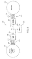
- a hybrid-electric propulsion system 200 includes a generator 202, an active rectifier 204, a battery 206, a motor drive 208, and a motor 210.
- AC links, e.g. AC links 108 described above, of active rectifier 204 are electrically connected to an AC output 212 of generator 202 through respective isolated AC phase windings 218 of generator 202, for converting alternating current energy to direct current energy.
- Battery 206 is electrically connected to a DC output 214 of active rectifier 204 for storing the direct current energy supplied through active rectifier 204.
- Motor drive 208 is electrically connected to a DC output 214 of active rectifier 204 and/or a DC output 215 of battery 206 for converting the direct current energy generated by active rectifier 204 and/or battery 206 into alternating current energy.
- Motor 210 includes isolated AC phase windings 218. Isolated AC phase windings 218 of motor 210 are electrically connected to an AC output 216 of motor drive 208 by way of respective AC links 108, as described above, of motor drive 208.
- Active rectifier 204 and motor drive 208 each include a respective DC bus 221 electrically connected to a respective set of phases 110, as described above with respect to Fig. 1 .
- motor drive 208 and active rectifier 204 can be bi-directional, e.g. power can flow from generator 202 to motor 210 or from motor 210 to generator 202.
- Respective power converter 100 within active rectifier 204 acts to convert alternating current energy, e.g. alternating current energy supplied through generator output 212, received from respective isolated AC phase windings 218 into direct current energy.
- Isolated AC phase windings 218 of generator 202 correspond to respective phases 219 of generator 202.
- the direct current energy is output through DC bus 112 to active rectifier output 214.
- the direct current energy output can either be stored in battery 206 or converted to alternating current energy by motor drive 208 for use in motor 210.
- generator 202 is shown with six-phases 219 to correspond its respective isolated AC phase windings 218, those skilled in the art will readily appreciate that generator 202 can have any number suitable phases as needed to connect to a respective power converter 100.
- Respective power converter 100 within motor drive 208 acts to convert direct current energy, e.g. direct current energy supplied through battery 206 or active rectifier output 214, received through DC bus 112 into alternating current energy.
- the alternating current energy is output to respective isolated AC phase windings 218 of the motor 210 from motor drive output 216.
- Isolated AC phase windings 218 of motor drive 208 correspond to its respective phases 217.
- the alternating current energy output through motor drive output 216 is used to drive motor 210.
- the isolated AC machine phase windings 218 when combined with the H-bridge configuration of power converter 100 of motor drive 208 allow a positive and negative peak AC phase winding voltage equal to the full voltage amplitude of DC link 214.
- This provides a ⁇ 3 higher motor winding voltage than would be achievable with a half bridge motor drive connection when powering a star-connected set of three-phase AC machine windings.
- the three-phase half bridge star-connected configuration tends to only allow the application of the full voltage amplitude of DC link 214 across the line to line connection of the motor windings.
- motor 210 is shown with six-phases 217 to correspond to its respective isolated AC phase windings 218, those skilled in the art will readily appreciate that motor 210 can have any number suitable phases as needed to connect to a respective power converter.
- hybrid-electric propulsion system 200 optionally includes a battery charger 205 electrically connected between the active rectifier 204 and battery 206 for controlling the current flow to or from battery 206. It is contemplated that the battery charger may be required for certain battery chemistries and for explicit control of the battery current, however including the charger may also increase cost and weight of system 200.
Landscapes
- Engineering & Computer Science (AREA)
- Power Engineering (AREA)
- Transportation (AREA)
- Mechanical Engineering (AREA)
- Inverter Devices (AREA)
- Rectifiers (AREA)
Applications Claiming Priority (1)
| Application Number | Priority Date | Filing Date | Title |
|---|---|---|---|
| US14/295,266 US9555711B2 (en) | 2014-06-03 | 2014-06-03 | Power converters |
Publications (3)
| Publication Number | Publication Date |
|---|---|
| EP2953256A2 true EP2953256A2 (de) | 2015-12-09 |
| EP2953256A3 EP2953256A3 (de) | 2016-04-20 |
| EP2953256B1 EP2953256B1 (de) | 2018-07-25 |
Family
ID=53199863
Family Applications (1)
| Application Number | Title | Priority Date | Filing Date |
|---|---|---|---|
| EP15169129.2A Active EP2953256B1 (de) | 2014-06-03 | 2015-05-26 | Stromwandler |
Country Status (2)
| Country | Link |
|---|---|
| US (1) | US9555711B2 (de) |
| EP (1) | EP2953256B1 (de) |
Families Citing this family (9)
| Publication number | Priority date | Publication date | Assignee | Title |
|---|---|---|---|---|
| DE102016209872A1 (de) | 2016-06-06 | 2017-12-07 | Continental Automotive Gmbh | Fahrzeugbordnetz mit Wechselrichter, Energiespeicher, elektrischer Maschine und Wechselstrom-Übertragungsanschluss |
| DE102016209898A1 (de) * | 2016-06-06 | 2017-12-07 | Continental Automotive Gmbh | Fahrzeugbordnetz mit Wechselrichter, Energiespeicher, elektrischer Maschine und Gleichstrom-Übertragungsanschluss |
| US20180187652A1 (en) * | 2017-01-05 | 2018-07-05 | General Electric Company | Power Converter for Full Conversion Wind Turbine Systems |
| US10110149B2 (en) * | 2017-01-06 | 2018-10-23 | General Electric Company | Grounding scheme for power converters with silicon carbide MOSFETs |
| US11264918B2 (en) | 2017-12-14 | 2022-03-01 | Kohler Co. | Isolated inverters |
| DE102018201202A1 (de) * | 2018-01-26 | 2019-08-01 | Siemens Aktiengesellschaft | Schaltungsanordnung für einen Umrichter, Verfahren zum Betrieb eines Umrichters und Luftfahrzeug mit einer derartigen Schaltungsanordnung |
| CN112075004A (zh) * | 2018-05-04 | 2020-12-11 | 奈克斯跟踪器有限公司 | 用于太阳能领域的dc功率转换和传输的系统和方法 |
| CN109873424B (zh) * | 2019-04-17 | 2019-11-22 | 山东大学 | 一种混合式级联apf拓扑结构及其控制方法 |
| US11799364B2 (en) | 2020-04-30 | 2023-10-24 | Kaney Aerospace, Inc. | Electric propulsion system having integrated electrical and thermal architecture and related methods of operating and implementing same |
Family Cites Families (14)
| Publication number | Priority date | Publication date | Assignee | Title |
|---|---|---|---|---|
| JP3844060B2 (ja) * | 2000-02-28 | 2006-11-08 | 株式会社安川電機 | Pwmパルス制御方法 |
| FR2860108B1 (fr) * | 2003-09-24 | 2007-01-19 | Johnson Contr Automotive Elect | Dispositif de redressement synchrone et machine electrique synchrone mettant en oeuvre le dispositif |
| US7050311B2 (en) * | 2003-11-25 | 2006-05-23 | Electric Power Research Institute, Inc. | Multilevel converter based intelligent universal transformer |
| US7072199B2 (en) * | 2004-04-06 | 2006-07-04 | Aimtron Technology Corp. | Motor control circuit for supplying a controllable driving voltage |
| US8184460B2 (en) * | 2009-05-28 | 2012-05-22 | General Electric Company | Solar inverter and control method |
| EP2348627A1 (de) * | 2010-01-25 | 2011-07-27 | ABB Research Ltd. | Wandlerschaltung sowie Verfahren zum Betreiben einer mehrstufigen Wandlerschaltung |
| US8441820B2 (en) * | 2010-09-29 | 2013-05-14 | General Electric Company | DC-link voltage balancing system and method for multilevel converters |
| US20120127769A1 (en) * | 2010-11-16 | 2012-05-24 | Sunedison, Llc | Soft Switching Power Converters |
| US20120218795A1 (en) * | 2011-02-28 | 2012-08-30 | Siemens Corporation | Pulse width modulated control for hybrid inverters |
| US20140241507A1 (en) | 2011-10-18 | 2014-08-28 | Koninklijke Philips N.V. | Electrical energy supply system |
| DE102011084698A1 (de) | 2011-10-18 | 2013-04-18 | Sb Limotive Company Ltd. | Umrichtereinheit für eine Asynchronmaschine |
| US8867248B2 (en) * | 2011-12-20 | 2014-10-21 | Kohler Co. | High-efficiency, three-level, single-phase inverter |
| US9214874B2 (en) | 2012-07-31 | 2015-12-15 | Yashomani Y. Kolhatkar | Intelligent level transition systems and methods for transformerless uninterruptible power supply |
| KR101791289B1 (ko) * | 2013-06-17 | 2017-10-27 | 엘에스산전 주식회사 | 멀티레벨 인버터 |
-
2014
- 2014-06-03 US US14/295,266 patent/US9555711B2/en active Active
-
2015
- 2015-05-26 EP EP15169129.2A patent/EP2953256B1/de active Active
Non-Patent Citations (1)
| Title |
|---|
| None |
Also Published As
| Publication number | Publication date |
|---|---|
| US9555711B2 (en) | 2017-01-31 |
| EP2953256A3 (de) | 2016-04-20 |
| US20150343911A1 (en) | 2015-12-03 |
| EP2953256B1 (de) | 2018-07-25 |
Similar Documents
| Publication | Publication Date | Title |
|---|---|---|
| EP2953256B1 (de) | Stromwandler | |
| CN109391166B (zh) | 一种变换电路、控制方法和供电设备 | |
| US9036379B2 (en) | Power converter based on H-bridges | |
| Rajeevan et al. | A nine-level inverter topology for medium-voltage induction motor drive with open-end stator winding | |
| EP1657809A1 (de) | Energieumsetzer, motorantrieb, btb-system und system-verbindungswechselrichtersystem | |
| US9184654B2 (en) | Assembly for converting an input AC voltage to an output AC voltage | |
| KR20130100285A (ko) | 영상 덤프 저항에 연결된 중성점을 갖는 hvdc 컨버터 | |
| US9847737B2 (en) | Modular multilevel converter leg with flat-top PWM modulation, converter and hybrid converter topologies | |
| JP6104736B2 (ja) | 電力変換装置 | |
| US20170317607A1 (en) | Three-level t-type npc power converter | |
| US20160028341A1 (en) | Systems and methods for zero common mode voltage | |
| WO2013151542A1 (en) | Multilevel converter | |
| CN108604797B (zh) | 多电平功率变流器及用于控制多电平功率变流器的方法 | |
| JP2004524795A (ja) | Vscコンバータ | |
| US11601046B2 (en) | Three-phase double t-type four-level rectifier | |
| EP2953257A1 (de) | 3-punkt npc umrichter mit inneren igbt und äusseren mosfet schaltern zum spannungsausgleich | |
| EP3915188A1 (de) | Motorantriebstopologien für zugkraft und ladung in elektrifizierten fahrzeugen | |
| Zhang et al. | Current source converter with switched-inductor DC link circuit for reduced converter losses | |
| Narimani et al. | A method to reduce zero-sequence circulating current in three-phase multi-module VSIs with reduced switch count | |
| Shahane et al. | A highly efficient Si/SiC based Hybrid Modular Multilevel H-bridge Converter for MV application | |
| Tan | Control and Modulation Techniques for the Five-Phase Coupled Inductor Inverter | |
| CN115179975A (zh) | 一种牵引传动系统 | |
| JP2020096440A (ja) | 電力変換装置 | |
| Lu et al. | Capacitor Voltage Balancing Control for Three-Level Single-Phase Neutral-Point-Clamped Inverter | |
| Bodhle et al. | Embeded control of Z-Source inverter |
Legal Events
| Date | Code | Title | Description |
|---|---|---|---|
| PUAI | Public reference made under article 153(3) epc to a published international application that has entered the european phase |
Free format text: ORIGINAL CODE: 0009012 |
|
| AK | Designated contracting states |
Kind code of ref document: A2 Designated state(s): AL AT BE BG CH CY CZ DE DK EE ES FI FR GB GR HR HU IE IS IT LI LT LU LV MC MK MT NL NO PL PT RO RS SE SI SK SM TR |
|
| AX | Request for extension of the european patent |
Extension state: BA ME |
|
| PUAL | Search report despatched |
Free format text: ORIGINAL CODE: 0009013 |
|
| AK | Designated contracting states |
Kind code of ref document: A3 Designated state(s): AL AT BE BG CH CY CZ DE DK EE ES FI FR GB GR HR HU IE IS IT LI LT LU LV MC MK MT NL NO PL PT RO RS SE SI SK SM TR |
|
| AX | Request for extension of the european patent |
Extension state: BA ME |
|
| RIC1 | Information provided on ipc code assigned before grant |
Ipc: H02M 7/487 20070101AFI20160317BHEP |
|
| 17P | Request for examination filed |
Effective date: 20161018 |
|
| RBV | Designated contracting states (corrected) |
Designated state(s): AL AT BE BG CH CY CZ DE DK EE ES FI FR GB GR HR HU IE IS IT LI LT LU LV MC MK MT NL NO PL PT RO RS SE SI SK SM TR |
|
| GRAP | Despatch of communication of intention to grant a patent |
Free format text: ORIGINAL CODE: EPIDOSNIGR1 |
|
| STAA | Information on the status of an ep patent application or granted ep patent |
Free format text: STATUS: GRANT OF PATENT IS INTENDED |
|
| INTG | Intention to grant announced |
Effective date: 20171020 |
|
| GRAJ | Information related to disapproval of communication of intention to grant by the applicant or resumption of examination proceedings by the epo deleted |
Free format text: ORIGINAL CODE: EPIDOSDIGR1 |
|
| STAA | Information on the status of an ep patent application or granted ep patent |
Free format text: STATUS: REQUEST FOR EXAMINATION WAS MADE |
|
| INTC | Intention to grant announced (deleted) | ||
| GRAP | Despatch of communication of intention to grant a patent |
Free format text: ORIGINAL CODE: EPIDOSNIGR1 |
|
| STAA | Information on the status of an ep patent application or granted ep patent |
Free format text: STATUS: GRANT OF PATENT IS INTENDED |
|
| INTG | Intention to grant announced |
Effective date: 20180216 |
|
| GRAS | Grant fee paid |
Free format text: ORIGINAL CODE: EPIDOSNIGR3 |
|
| GRAA | (expected) grant |
Free format text: ORIGINAL CODE: 0009210 |
|
| STAA | Information on the status of an ep patent application or granted ep patent |
Free format text: STATUS: THE PATENT HAS BEEN GRANTED |
|
| AK | Designated contracting states |
Kind code of ref document: B1 Designated state(s): AL AT BE BG CH CY CZ DE DK EE ES FI FR GB GR HR HU IE IS IT LI LT LU LV MC MK MT NL NO PL PT RO RS SE SI SK SM TR |
|
| REG | Reference to a national code |
Ref country code: GB Ref legal event code: FG4D |
|
| REG | Reference to a national code |
Ref country code: CH Ref legal event code: EP |
|
| REG | Reference to a national code |
Ref country code: AT Ref legal event code: REF Ref document number: 1022839 Country of ref document: AT Kind code of ref document: T Effective date: 20180815 |
|
| REG | Reference to a national code |
Ref country code: IE Ref legal event code: FG4D |
|
| REG | Reference to a national code |
Ref country code: DE Ref legal event code: R096 Ref document number: 602015013880 Country of ref document: DE |
|
| REG | Reference to a national code |
Ref country code: NL Ref legal event code: MP Effective date: 20180725 |
|
| REG | Reference to a national code |
Ref country code: LT Ref legal event code: MG4D |
|
| PG25 | Lapsed in a contracting state [announced via postgrant information from national office to epo] |
Ref country code: NL Free format text: LAPSE BECAUSE OF FAILURE TO SUBMIT A TRANSLATION OF THE DESCRIPTION OR TO PAY THE FEE WITHIN THE PRESCRIBED TIME-LIMIT Effective date: 20180725 |
|
| REG | Reference to a national code |
Ref country code: AT Ref legal event code: MK05 Ref document number: 1022839 Country of ref document: AT Kind code of ref document: T Effective date: 20180725 |
|
| PG25 | Lapsed in a contracting state [announced via postgrant information from national office to epo] |
Ref country code: NO Free format text: LAPSE BECAUSE OF FAILURE TO SUBMIT A TRANSLATION OF THE DESCRIPTION OR TO PAY THE FEE WITHIN THE PRESCRIBED TIME-LIMIT Effective date: 20181025 Ref country code: AT Free format text: LAPSE BECAUSE OF FAILURE TO SUBMIT A TRANSLATION OF THE DESCRIPTION OR TO PAY THE FEE WITHIN THE PRESCRIBED TIME-LIMIT Effective date: 20180725 Ref country code: LT Free format text: LAPSE BECAUSE OF FAILURE TO SUBMIT A TRANSLATION OF THE DESCRIPTION OR TO PAY THE FEE WITHIN THE PRESCRIBED TIME-LIMIT Effective date: 20180725 Ref country code: BG Free format text: LAPSE BECAUSE OF FAILURE TO SUBMIT A TRANSLATION OF THE DESCRIPTION OR TO PAY THE FEE WITHIN THE PRESCRIBED TIME-LIMIT Effective date: 20181025 Ref country code: PL Free format text: LAPSE BECAUSE OF FAILURE TO SUBMIT A TRANSLATION OF THE DESCRIPTION OR TO PAY THE FEE WITHIN THE PRESCRIBED TIME-LIMIT Effective date: 20180725 Ref country code: IS Free format text: LAPSE BECAUSE OF FAILURE TO SUBMIT A TRANSLATION OF THE DESCRIPTION OR TO PAY THE FEE WITHIN THE PRESCRIBED TIME-LIMIT Effective date: 20181125 Ref country code: SE Free format text: LAPSE BECAUSE OF FAILURE TO SUBMIT A TRANSLATION OF THE DESCRIPTION OR TO PAY THE FEE WITHIN THE PRESCRIBED TIME-LIMIT Effective date: 20180725 Ref country code: RS Free format text: LAPSE BECAUSE OF FAILURE TO SUBMIT A TRANSLATION OF THE DESCRIPTION OR TO PAY THE FEE WITHIN THE PRESCRIBED TIME-LIMIT Effective date: 20180725 Ref country code: GR Free format text: LAPSE BECAUSE OF FAILURE TO SUBMIT A TRANSLATION OF THE DESCRIPTION OR TO PAY THE FEE WITHIN THE PRESCRIBED TIME-LIMIT Effective date: 20181026 Ref country code: FI Free format text: LAPSE BECAUSE OF FAILURE TO SUBMIT A TRANSLATION OF THE DESCRIPTION OR TO PAY THE FEE WITHIN THE PRESCRIBED TIME-LIMIT Effective date: 20180725 |
|
| PG25 | Lapsed in a contracting state [announced via postgrant information from national office to epo] |
Ref country code: AL Free format text: LAPSE BECAUSE OF FAILURE TO SUBMIT A TRANSLATION OF THE DESCRIPTION OR TO PAY THE FEE WITHIN THE PRESCRIBED TIME-LIMIT Effective date: 20180725 Ref country code: LV Free format text: LAPSE BECAUSE OF FAILURE TO SUBMIT A TRANSLATION OF THE DESCRIPTION OR TO PAY THE FEE WITHIN THE PRESCRIBED TIME-LIMIT Effective date: 20180725 Ref country code: HR Free format text: LAPSE BECAUSE OF FAILURE TO SUBMIT A TRANSLATION OF THE DESCRIPTION OR TO PAY THE FEE WITHIN THE PRESCRIBED TIME-LIMIT Effective date: 20180725 |
|
| REG | Reference to a national code |
Ref country code: DE Ref legal event code: R097 Ref document number: 602015013880 Country of ref document: DE |
|
| PG25 | Lapsed in a contracting state [announced via postgrant information from national office to epo] |
Ref country code: EE Free format text: LAPSE BECAUSE OF FAILURE TO SUBMIT A TRANSLATION OF THE DESCRIPTION OR TO PAY THE FEE WITHIN THE PRESCRIBED TIME-LIMIT Effective date: 20180725 Ref country code: IT Free format text: LAPSE BECAUSE OF FAILURE TO SUBMIT A TRANSLATION OF THE DESCRIPTION OR TO PAY THE FEE WITHIN THE PRESCRIBED TIME-LIMIT Effective date: 20180725 Ref country code: RO Free format text: LAPSE BECAUSE OF FAILURE TO SUBMIT A TRANSLATION OF THE DESCRIPTION OR TO PAY THE FEE WITHIN THE PRESCRIBED TIME-LIMIT Effective date: 20180725 Ref country code: CZ Free format text: LAPSE BECAUSE OF FAILURE TO SUBMIT A TRANSLATION OF THE DESCRIPTION OR TO PAY THE FEE WITHIN THE PRESCRIBED TIME-LIMIT Effective date: 20180725 Ref country code: ES Free format text: LAPSE BECAUSE OF FAILURE TO SUBMIT A TRANSLATION OF THE DESCRIPTION OR TO PAY THE FEE WITHIN THE PRESCRIBED TIME-LIMIT Effective date: 20180725 |
|
| PG25 | Lapsed in a contracting state [announced via postgrant information from national office to epo] |
Ref country code: SK Free format text: LAPSE BECAUSE OF FAILURE TO SUBMIT A TRANSLATION OF THE DESCRIPTION OR TO PAY THE FEE WITHIN THE PRESCRIBED TIME-LIMIT Effective date: 20180725 Ref country code: SM Free format text: LAPSE BECAUSE OF FAILURE TO SUBMIT A TRANSLATION OF THE DESCRIPTION OR TO PAY THE FEE WITHIN THE PRESCRIBED TIME-LIMIT Effective date: 20180725 Ref country code: DK Free format text: LAPSE BECAUSE OF FAILURE TO SUBMIT A TRANSLATION OF THE DESCRIPTION OR TO PAY THE FEE WITHIN THE PRESCRIBED TIME-LIMIT Effective date: 20180725 |
|
| PLBE | No opposition filed within time limit |
Free format text: ORIGINAL CODE: 0009261 |
|
| STAA | Information on the status of an ep patent application or granted ep patent |
Free format text: STATUS: NO OPPOSITION FILED WITHIN TIME LIMIT |
|
| 26N | No opposition filed |
Effective date: 20190426 |
|
| PG25 | Lapsed in a contracting state [announced via postgrant information from national office to epo] |
Ref country code: SI Free format text: LAPSE BECAUSE OF FAILURE TO SUBMIT A TRANSLATION OF THE DESCRIPTION OR TO PAY THE FEE WITHIN THE PRESCRIBED TIME-LIMIT Effective date: 20180725 |
|
| REG | Reference to a national code |
Ref country code: CH Ref legal event code: PL |
|
| PG25 | Lapsed in a contracting state [announced via postgrant information from national office to epo] |
Ref country code: MC Free format text: LAPSE BECAUSE OF FAILURE TO SUBMIT A TRANSLATION OF THE DESCRIPTION OR TO PAY THE FEE WITHIN THE PRESCRIBED TIME-LIMIT Effective date: 20180725 Ref country code: CH Free format text: LAPSE BECAUSE OF NON-PAYMENT OF DUE FEES Effective date: 20190531 Ref country code: LI Free format text: LAPSE BECAUSE OF NON-PAYMENT OF DUE FEES Effective date: 20190531 |
|
| REG | Reference to a national code |
Ref country code: BE Ref legal event code: MM Effective date: 20190531 |
|
| PG25 | Lapsed in a contracting state [announced via postgrant information from national office to epo] |
Ref country code: LU Free format text: LAPSE BECAUSE OF NON-PAYMENT OF DUE FEES Effective date: 20190526 |
|
| PG25 | Lapsed in a contracting state [announced via postgrant information from national office to epo] |
Ref country code: TR Free format text: LAPSE BECAUSE OF FAILURE TO SUBMIT A TRANSLATION OF THE DESCRIPTION OR TO PAY THE FEE WITHIN THE PRESCRIBED TIME-LIMIT Effective date: 20180725 |
|
| PG25 | Lapsed in a contracting state [announced via postgrant information from national office to epo] |
Ref country code: IE Free format text: LAPSE BECAUSE OF NON-PAYMENT OF DUE FEES Effective date: 20190526 |
|
| PG25 | Lapsed in a contracting state [announced via postgrant information from national office to epo] |
Ref country code: BE Free format text: LAPSE BECAUSE OF NON-PAYMENT OF DUE FEES Effective date: 20190531 |
|
| PG25 | Lapsed in a contracting state [announced via postgrant information from national office to epo] |
Ref country code: PT Free format text: LAPSE BECAUSE OF FAILURE TO SUBMIT A TRANSLATION OF THE DESCRIPTION OR TO PAY THE FEE WITHIN THE PRESCRIBED TIME-LIMIT Effective date: 20181125 |
|
| PG25 | Lapsed in a contracting state [announced via postgrant information from national office to epo] |
Ref country code: CY Free format text: LAPSE BECAUSE OF FAILURE TO SUBMIT A TRANSLATION OF THE DESCRIPTION OR TO PAY THE FEE WITHIN THE PRESCRIBED TIME-LIMIT Effective date: 20180725 |
|
| PG25 | Lapsed in a contracting state [announced via postgrant information from national office to epo] |
Ref country code: MT Free format text: LAPSE BECAUSE OF FAILURE TO SUBMIT A TRANSLATION OF THE DESCRIPTION OR TO PAY THE FEE WITHIN THE PRESCRIBED TIME-LIMIT Effective date: 20180725 Ref country code: HU Free format text: LAPSE BECAUSE OF FAILURE TO SUBMIT A TRANSLATION OF THE DESCRIPTION OR TO PAY THE FEE WITHIN THE PRESCRIBED TIME-LIMIT; INVALID AB INITIO Effective date: 20150526 |
|
| PG25 | Lapsed in a contracting state [announced via postgrant information from national office to epo] |
Ref country code: MK Free format text: LAPSE BECAUSE OF FAILURE TO SUBMIT A TRANSLATION OF THE DESCRIPTION OR TO PAY THE FEE WITHIN THE PRESCRIBED TIME-LIMIT Effective date: 20180725 |
|
| P01 | Opt-out of the competence of the unified patent court (upc) registered |
Effective date: 20230522 |
|
| PGFP | Annual fee paid to national office [announced via postgrant information from national office to epo] |
Ref country code: FR Payment date: 20230420 Year of fee payment: 9 Ref country code: DE Payment date: 20230419 Year of fee payment: 9 |
|
| PGFP | Annual fee paid to national office [announced via postgrant information from national office to epo] |
Ref country code: GB Payment date: 20230420 Year of fee payment: 9 |