EP2953245A1 - Induit à cage d'écureuil d'une machine asynchrone - Google Patents
Induit à cage d'écureuil d'une machine asynchrone Download PDFInfo
- Publication number
- EP2953245A1 EP2953245A1 EP15168066.7A EP15168066A EP2953245A1 EP 2953245 A1 EP2953245 A1 EP 2953245A1 EP 15168066 A EP15168066 A EP 15168066A EP 2953245 A1 EP2953245 A1 EP 2953245A1
- Authority
- EP
- European Patent Office
- Prior art keywords
- laminated core
- squirrel cage
- conductor
- asynchronous machine
- rotor
- Prior art date
- Legal status (The legal status is an assumption and is not a legal conclusion. Google has not performed a legal analysis and makes no representation as to the accuracy of the status listed.)
- Granted
Links
- 239000004020 conductor Substances 0.000 claims abstract description 67
- 239000000463 material Substances 0.000 claims abstract description 28
- 241000555745 Sciuridae Species 0.000 claims description 21
- 229910045601 alloy Inorganic materials 0.000 claims description 11
- 239000000956 alloy Substances 0.000 claims description 11
- 238000000034 method Methods 0.000 claims description 6
- 238000004519 manufacturing process Methods 0.000 claims description 3
- 230000002093 peripheral effect Effects 0.000 claims description 3
- 238000005538 encapsulation Methods 0.000 claims description 2
- 238000004080 punching Methods 0.000 claims description 2
- 239000007787 solid Substances 0.000 claims 4
- 238000003780 insertion Methods 0.000 claims 1
- 230000037431 insertion Effects 0.000 claims 1
- 238000012856 packing Methods 0.000 claims 1
- 150000001875 compounds Chemical class 0.000 description 22
- 238000004382 potting Methods 0.000 description 17
- XAGFODPZIPBFFR-UHFFFAOYSA-N aluminium Chemical compound [Al] XAGFODPZIPBFFR-UHFFFAOYSA-N 0.000 description 14
- 229910052782 aluminium Inorganic materials 0.000 description 14
- 229910052802 copper Inorganic materials 0.000 description 14
- 239000010949 copper Substances 0.000 description 14
- RYGMFSIKBFXOCR-UHFFFAOYSA-N Copper Chemical compound [Cu] RYGMFSIKBFXOCR-UHFFFAOYSA-N 0.000 description 13
- 238000000576 coating method Methods 0.000 description 13
- 229910000838 Al alloy Inorganic materials 0.000 description 11
- 239000011248 coating agent Substances 0.000 description 11
- 238000004512 die casting Methods 0.000 description 8
- 238000005266 casting Methods 0.000 description 3
- 238000009713 electroplating Methods 0.000 description 3
- 239000000155 melt Substances 0.000 description 3
- 238000005516 engineering process Methods 0.000 description 2
- 238000005507 spraying Methods 0.000 description 2
- 230000007704 transition Effects 0.000 description 2
- 238000004804 winding Methods 0.000 description 2
- 238000005275 alloying Methods 0.000 description 1
- 230000004323 axial length Effects 0.000 description 1
- 230000015572 biosynthetic process Effects 0.000 description 1
- 238000006243 chemical reaction Methods 0.000 description 1
- 238000010288 cold spraying Methods 0.000 description 1
- 150000001879 copper Chemical class 0.000 description 1
- 230000006866 deterioration Effects 0.000 description 1
- ZINJLDJMHCUBIP-UHFFFAOYSA-N ethametsulfuron-methyl Chemical compound CCOC1=NC(NC)=NC(NC(=O)NS(=O)(=O)C=2C(=CC=CC=2)C(=O)OC)=N1 ZINJLDJMHCUBIP-UHFFFAOYSA-N 0.000 description 1
- 238000001125 extrusion Methods 0.000 description 1
- 238000010285 flame spraying Methods 0.000 description 1
- 230000003993 interaction Effects 0.000 description 1
- 230000001788 irregular Effects 0.000 description 1
- 238000007750 plasma spraying Methods 0.000 description 1
- 238000007747 plating Methods 0.000 description 1
- 230000001373 regressive effect Effects 0.000 description 1
- 238000007789 sealing Methods 0.000 description 1
- 239000000126 substance Substances 0.000 description 1
- 238000007751 thermal spraying Methods 0.000 description 1
- 238000007740 vapor deposition Methods 0.000 description 1
Images


Classifications
-
- H—ELECTRICITY
- H02—GENERATION; CONVERSION OR DISTRIBUTION OF ELECTRIC POWER
- H02K—DYNAMO-ELECTRIC MACHINES
- H02K17/00—Asynchronous induction motors; Asynchronous induction generators
- H02K17/02—Asynchronous induction motors
- H02K17/16—Asynchronous induction motors having rotors with internally short-circuited windings, e.g. cage rotors
- H02K17/165—Asynchronous induction motors having rotors with internally short-circuited windings, e.g. cage rotors characterised by the squirrel-cage or other short-circuited windings
-
- H—ELECTRICITY
- H02—GENERATION; CONVERSION OR DISTRIBUTION OF ELECTRIC POWER
- H02K—DYNAMO-ELECTRIC MACHINES
- H02K15/00—Methods or apparatus specially adapted for manufacturing, assembling, maintaining or repairing of dynamo-electric machines
- H02K15/0012—Manufacturing cage rotors
-
- H—ELECTRICITY
- H02—GENERATION; CONVERSION OR DISTRIBUTION OF ELECTRIC POWER
- H02K—DYNAMO-ELECTRIC MACHINES
- H02K17/00—Asynchronous induction motors; Asynchronous induction generators
- H02K17/02—Asynchronous induction motors
- H02K17/16—Asynchronous induction motors having rotors with internally short-circuited windings, e.g. cage rotors
- H02K17/18—Asynchronous induction motors having rotors with internally short-circuited windings, e.g. cage rotors having double-cage or multiple-cage rotors
-
- H—ELECTRICITY
- H02—GENERATION; CONVERSION OR DISTRIBUTION OF ELECTRIC POWER
- H02K—DYNAMO-ELECTRIC MACHINES
- H02K17/00—Asynchronous induction motors; Asynchronous induction generators
- H02K17/02—Asynchronous induction motors
- H02K17/16—Asynchronous induction motors having rotors with internally short-circuited windings, e.g. cage rotors
- H02K17/20—Asynchronous induction motors having rotors with internally short-circuited windings, e.g. cage rotors having deep-bar rotors
-
- H—ELECTRICITY
- H02—GENERATION; CONVERSION OR DISTRIBUTION OF ELECTRIC POWER
- H02K—DYNAMO-ELECTRIC MACHINES
- H02K3/00—Details of windings
- H02K3/02—Windings characterised by the conductor material
-
- Y—GENERAL TAGGING OF NEW TECHNOLOGICAL DEVELOPMENTS; GENERAL TAGGING OF CROSS-SECTIONAL TECHNOLOGIES SPANNING OVER SEVERAL SECTIONS OF THE IPC; TECHNICAL SUBJECTS COVERED BY FORMER USPC CROSS-REFERENCE ART COLLECTIONS [XRACs] AND DIGESTS
- Y10—TECHNICAL SUBJECTS COVERED BY FORMER USPC
- Y10T—TECHNICAL SUBJECTS COVERED BY FORMER US CLASSIFICATION
- Y10T29/00—Metal working
- Y10T29/49—Method of mechanical manufacture
- Y10T29/49002—Electrical device making
- Y10T29/49014—Superconductor
Definitions
- the invention relates to a squirrel cage rotor asynchronous machine with axially stacked laminated core having substantially axially extending grooves in which an electrical conductor is located, which forms with the electrical conductors in other grooves on the respective end faces of the laminated core shorting rings and so forms a squirrel cage.
- the rotor in particular the short-circuit ring, is a weak point. It comes at the short-circuit ring by the centrifugal forces to irregular widening, which make an impermissible non-regressive changes and in so far as an imbalance in the runner noticeable. This occurs especially with short-circuited rings that use pure aluminum (AL99.5) as the electrically conductive potting compound. Although the electrical conductance is relatively high, but this material is not suitable for high centrifugal force.
- the present invention seeks to provide a squirrel cage an asynchronous machine that holds both the centrifugal stresses withstand, as well as comparatively little loss.
- This material is equipped with comparatively good technical properties for die casting by being pourable at comparatively low temperatures.
- the speed suitability of the short-circuit ring is thereby considerably increased, since this potting compound only comes into a plastic range at higher speeds.
- aluminum rods Al 99.7 with a conductance of 36 m / ohm mm 2 with corresponding groove geometries and a certain groove filling are inserted into the groove. For example, 85% of the groove filling by Al-rod and 15% potting compound.
- the comparatively lower conductance in the short-circuit ring can be compensated by increasing the cross-section by a factor of 1.7.
- the inserted copper rod must be designed in a specially designed for high speed geometry, so it does not come to a demolition of the contact surface of the rod to the cast short-circuit ring due to the high tangential stresses.
- This copper rod has special geometries for high speeds and tangential stresses in the short-circuit ring.
- the rod is coated.
- connection between the conductors and the short-circuit rings is improved by the materials forming a mixed-crystalline compound at suitable points.
- the shorting bars project axially out of both ends of the rotor core and into the molded shorting rings.
- the increase in the bonding forces between conductor ends and short-circuiting rings is u.a. achieved in that the sub-conductors - ie the rods of aluminum or copper - are coated such that both between the coating and the conductors an alloy - ie a mixed crystalline compound - arises, as well as between the coating and the cast material of the shorting rings.
- Läufererblechonce can also axially expand again when the connection between the sub-conductors - ie the rods - and the cast shorting rings can not muster sufficient axial holding force.
- the conductors are bonded to the die casting by means of maximum possible bonding forces. Accordingly, the connection between the conductors and the short circuit rings remains stable despite possibly different thermal expansion coefficients, when the squirrel cage passes through pronounced thermal cycles during operation of the dynamoelectric machine. At high speeds, the centrifugal forces acting on the rotor also partly cause violent stresses in the conductor-shorting ring. Furthermore, the alloy achieves an optimum electrical conductance between the materials.
- the coating and the first alloy layer can be produced by electromechanical plating.
- a layer of the coating material is deposited on the rods by electrochemical means.
- the desired mixed-crystalline compound is formed between the rod and the coating material.
- subsequently diecasting material that is to say Al
- the coating melts on the rods and also forms a mixed-crystalline compound with the diecasting melt, so that a second alloying layer is formed.
- thermal spraying in particular flame spraying, plasma spraying, arc spraying or laser spraying, is particularly suitable.
- this layer can be produced by cold spraying or by vapor deposition.
- an oxide layer of the conductors is removed by chemical pretreatment of these conductors prior to coating.
- An oxide layer has insulating electrical properties, so that the removal of said oxide layer significantly reduces the contact resistance between the materials.
- a thin aluminum layer is applied to the surface of the copper conductors in a hybrid rotor with copper rods and aluminum short-circuiting rings. This can be done for example by electroplating. This coating process creates an alloy between the aluminum coating and the copper conductors. Subsequently, an aluminum diecasting compound is injected into the grooves, at the same time as the short-circuiting rings are poured out. Here, the aluminum coating is melted on the surface of the ladder and enters with the molten aluminum a mixed crystalline compound. It will finally formed the second alloy layer.
- the casting process can lead to significant chemical reactions between the coated partial conductors, ie the rods and the melt.
- the coating and the alloy layers can be arranged exclusively on end portions of the conductors projecting out of the rotor core and out into the shorting rings.
- the said end regions represent a critical connection point between the conductors and the short-circuiting rings. Accordingly, here the strong crystalline connection of the materials and sub-conductors involved is particularly important.
- the short-circuit ring on a support ring and thus prevents plastic expansion due to the centrifugal forces at speeds, with peripheral speeds greater than 125 m / s.
- the support ring is made of a material corresponding in thermal expansion to that of the shorting ring to be supported, e.g.
- EN AW-7075 Preferably of an aluminum alloy with very high tensile strength.
- the support ring can also be obtained from an extrusion material having the required material characteristics.
- high-strength aluminum alloys offer tensile strengths in the range of 500 N / mm 2 .
- These high-strength aluminum alloys with a thermal expansion coefficient of 23.6x10 -6 1 / K correspond to the thermal expansion coefficient of pure aluminum.
- the reduced electrical conductivity of the potting compound is compensated for high rotational speeds by introducing aluminum or copper rods in the groove.
- a high speed suitability of the asynchronous machine is achieved at the same time high conductance in the groove.
- a flow of the potting compound is prevented by interaction of the support ring.
- the material of the support ring has the same thermal expansion coefficient as the short-circuit ring with high tensile strength.
- a temperature range of -40 ° C to + 250 ° C of the dynamoelectric machine can be secured.
- Speeds in the range of 200 to 230 m / s peripheral speed can thus be realized for squirrel-cage according to the invention.
- the allowable yield strength of the support ring can thus be used only for the load from the centrifugal force at high speed and is not already “consumed” by the thermal expansion of the shorting ring. Therefore, an aluminum alloy with tensile strength of 540 N / mm 2 is sufficient.
- a high strength aluminum alloy e.g. AL7075 with high tensile strength can thus speed increases compared to conventional arrangements of up to 70% can be achieved, whereby in particular specifications from the automotive industry (motors for electrically powered cars and buses, purely electric and hybrid drives), or covered in the compressor technology.
- FIG. 1 shows a schematic representation of the longitudinal section of a dynamoelectric machine, which is designed as an asynchronous motor, wherein a housing 18, the bearing plates 8 receives a shaft 4 holds on which a rotor or rotor 5 is rotatably connected to its laminated core.
- the rotor or rotor 5 is referred to in the context of this invention as a squirrel cage.
- the shaft 4 rotates about an axis 20.
- a short-circuit ring 6, which connects the axially from the grooves 9 passing conductor of the rotor 5 at the end faces electrically.
- Radially outside the rotor 5 is, spaced by an air gap 19, a stator 2, which has on its end sides winding heads of a winding system 3.
- FIG. 2 shows in a partial cross section of the rotor 5 transverse to an axis 20, two partial conductors, an aluminum rod and a sub-conductor in Nutkopf Suite in aluminum alloy.
- the tangential stress 15 and radial stresses 16 occurring during operation of the asynchronous motor are - as in the following figures - marked with arrows in this section of the rotor 5.
- a contact surface 11 is present between the rotor plate and the conductor bar 13, a contact surface 11 is present.
- FIG. 3 shows in a partial longitudinal section a short-circuit ring 6, a rotor 5 after FIG. 2 , which is supported by a support ring 14 against radial forces - ie centrifugal forces - during operation of the asynchronous motor.
- a sub-conductor 13 - that is, a rod - protrudes axially over the end face of the laminated core 10 of the rotor 5 in the short-circuit ring 6.
- the groove head is also executed there in an aluminum alloy.
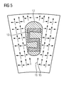
- FIG. 4 and FIG. 5 show in cross-section a short-circuit ring with special bars, ie sub-conductor 13 for high speed, where also there the radial and tangential voltages are indicated by arrows.
- the conductor bar 13 is after FIG. 4 comb-like and after FIG. 5 S-shaped designed to provide the largest possible contact surface of the rod contour within the short-circuit ring 6.
- the conductor bars or sub-conductors 13 are designed comb-like or S-shaped over their entire axial length.
- sub-conductors 13 only partially,
- comb-like, double comb-like, gear-shaped, star-shaped or S-shaped are executed.
- FIG. 6 shows a partial cross section of a groove 9, which is executed in the direction of the air gap 18 through a slot slot 17, wherein the sub-conductor 12 in the Nutkopf Scheme in the groove slot 17 protrudes.
- a leakage inductance sets in which can be advantageous for a converter operation of the dynamoelectric machine.
- the following versions of the squirrel-cage rotor are especially designed for high speeds and are therefore particularly suitable for applications in vehicle technology in e-cars (direct or hybrid drive) and in compressor drives.
- e-cars direct or hybrid drive
- compressor drives are especially suitable for applications in vehicle technology in e-cars (direct or hybrid drive) and in compressor drives.
- further material combinations of a squirrel cage are possible if materials with similar material characteristics are used.
- the Bar has a squirrel cage with bars or sub-conductor 13 of pure Al, a casting material ALSI9Cu3, the Bar at least partially surrounds and with a support ring 14 made of alloy AW7075 a comparatively high conductance at very high speed suitability.
- rod and potting compound have the same coefficient of expansion. The rod connection to the short-circuit ring 6 succeeds particularly well due to the two AL components.
- a squirrel cage rotor with rods or conductor 13 of copper, a casting material ALSI9Cu3, which surrounds the rod at least partially and with a support ring 14 of the alloy AW7075 also has a comparatively high conductance at very high speed suitability.
- special contours of the copper rod are necessary in order to obtain a sufficient rod connection of the copper rods in the cast short-circuit ring 6.
Landscapes
- Engineering & Computer Science (AREA)
- Power Engineering (AREA)
- Manufacturing & Machinery (AREA)
- Induction Machinery (AREA)
Applications Claiming Priority (1)
| Application Number | Priority Date | Filing Date | Title |
|---|---|---|---|
| DE102014210339.8A DE102014210339A1 (de) | 2014-06-02 | 2014-06-02 | Käfigläufer einer Asynchronmaschine |
Publications (2)
| Publication Number | Publication Date |
|---|---|
| EP2953245A1 true EP2953245A1 (fr) | 2015-12-09 |
| EP2953245B1 EP2953245B1 (fr) | 2017-09-13 |
Family
ID=53180605
Family Applications (1)
| Application Number | Title | Priority Date | Filing Date |
|---|---|---|---|
| EP15168066.7A Active EP2953245B1 (fr) | 2014-06-02 | 2015-05-19 | Induit à cage d'écureuil d'une machine asynchrone |
Country Status (4)
| Country | Link |
|---|---|
| US (1) | US10027211B2 (fr) |
| EP (1) | EP2953245B1 (fr) |
| CN (1) | CN105305752B (fr) |
| DE (1) | DE102014210339A1 (fr) |
Cited By (5)
| Publication number | Priority date | Publication date | Assignee | Title |
|---|---|---|---|---|
| EP3288159A1 (fr) * | 2016-08-24 | 2018-02-28 | Siemens Aktiengesellschaft | Rotor en court-circuit en particulier pour dispositifs a haut regime |
| EP3322070A1 (fr) * | 2016-11-11 | 2018-05-16 | Hamilton Sundstrand Corporation | Conducteurs multicouches pour une perte de foucault réduite |
| EP3373424A1 (fr) * | 2017-03-10 | 2018-09-12 | Siemens Aktiengesellschaft | Fabrication additive d'un rotor |
| EP3382864A1 (fr) * | 2017-03-29 | 2018-10-03 | Siemens Aktiengesellschaft | Cage d'écureuil hybride |
| EP3627661A1 (fr) * | 2018-09-21 | 2020-03-25 | Siemens Aktiengesellschaft | Induit à cage d'ecureuil et fabrication d'un induit à cage d'ecureuil |
Families Citing this family (12)
| Publication number | Priority date | Publication date | Assignee | Title |
|---|---|---|---|---|
| WO2014166674A2 (fr) * | 2013-04-11 | 2014-10-16 | Siemens Aktiengesellschaft | Moteur à réluctance et rotor correspondant |
| EP2928047A1 (fr) | 2014-03-31 | 2015-10-07 | Siemens Aktiengesellschaft | Rotor à réluctance à stabilisation mécanique |
| EP3070824A1 (fr) | 2015-03-19 | 2016-09-21 | Siemens Aktiengesellschaft | Rotor d'une machine à réluctance synchrone |
| BR112018000809A2 (pt) | 2015-07-17 | 2018-09-04 | Siemens Ag | rotor, máquina elétrica, e, método para fabricar um rotor |
| ES2667490T3 (es) | 2015-12-14 | 2018-05-11 | Siemens Aktiengesellschaft | Alineación de rotor para la reducción de las vibraciones y los ruidos |
| EP3193431A1 (fr) | 2016-01-14 | 2017-07-19 | Siemens Aktiengesellschaft | Tole electrique dotee d'une ame imprimee |
| EP3258578A1 (fr) * | 2016-06-16 | 2017-12-20 | Siemens Aktiengesellschaft | Induit a cage d'ecureuil d'une machine asynchrone |
| EP3402057A1 (fr) * | 2017-05-09 | 2018-11-14 | Siemens Aktiengesellschaft | Procédé de fabrication d'un rotor à cage d'écureuil d'une machine asynchrone |
| FR3069725B1 (fr) * | 2017-07-31 | 2021-01-29 | Leroy Somer Moteurs | Rotor a cage injectee |
| EP3629452A1 (fr) | 2018-09-28 | 2020-04-01 | Siemens Aktiengesellschaft | Procédé de fabrication d'un rotor pour une machine à rotation électrique |
| DE102020121380A1 (de) | 2020-08-14 | 2022-02-17 | Dr. Ing. H.C. F. Porsche Aktiengesellschaft | Stator für eine elektrische Maschine, Verfahren zu seiner Herstellung, elektrische Maschine und Kraftfahrzeug |
| JP2023026866A (ja) * | 2021-08-16 | 2023-03-01 | 株式会社日立インダストリアルプロダクツ | 誘導電動機および鉄道車両 |
Citations (6)
| Publication number | Priority date | Publication date | Assignee | Title |
|---|---|---|---|---|
| GB822313A (en) * | 1957-01-03 | 1959-10-21 | Scott L & Electromotors Ltd | Improvements in deep bar rotor induction motors |
| US20050017597A1 (en) * | 2003-07-23 | 2005-01-27 | Mays Harold H. | End ring support structure for electric motor |
| DE102005030797A1 (de) * | 2005-06-29 | 2007-01-04 | Siemens Ag | Käfigläufer einer Induktionsmaschine |
| DE102009008440B3 (de) | 2009-02-11 | 2010-12-02 | Siemens Aktiengesellschaft | Käfigläufer |
| DE102010041795A1 (de) * | 2010-09-30 | 2012-04-05 | Siemens Aktiengesellschaft | Käfigläufer |
| US20140139066A1 (en) * | 2012-11-22 | 2014-05-22 | Kabushiki Kaisha Yaskawa Denki | Rotary electric apparatus and rotor |
Family Cites Families (27)
| Publication number | Priority date | Publication date | Assignee | Title |
|---|---|---|---|---|
| US1777320A (en) * | 1929-10-14 | 1930-10-07 | Mccollum Hoist & Mfg Co | Rotor |
| US2794138A (en) * | 1954-05-27 | 1957-05-28 | Gen Electric | Closed slot rotor punching |
| US3027474A (en) * | 1956-09-04 | 1962-03-27 | Gen Electric | Squirrel cage induction motor rotor |
| US3290526A (en) * | 1963-08-05 | 1966-12-06 | Westinghouse Electric Corp | Induction motor rotor |
| US3659129A (en) * | 1970-09-15 | 1972-04-25 | Gen Electric | Insulated bar dynamoelectric machine and method of forming |
| US3778652A (en) * | 1972-08-08 | 1973-12-11 | Carrier Corp | Rotor structure with squirrel cage winding |
| JPH04351450A (ja) * | 1991-05-30 | 1992-12-07 | Toshiba Corp | かご形回転子 |
| AT402771B (de) * | 1992-12-01 | 1997-08-25 | Elin Motoren Gmbh | Rotornut |
| US6088906A (en) * | 1997-09-16 | 2000-07-18 | Ut-Battelle, Llc | Method of manufacturing squirrel cage rotors |
| US6246141B1 (en) * | 1999-04-23 | 2001-06-12 | Hamilton Sundstrand Corporation | High torque reduced starting current electric motor |
| EP2282396B1 (fr) | 2009-08-03 | 2012-12-05 | Siemens Aktiengesellschaft | Procédé de fabrication pour rotor à cage d'écureuil oblique et rotor à cage d'écureuil oblique |
| EP2288004B1 (fr) * | 2009-08-19 | 2017-05-17 | Siemens Aktiengesellschaft | Cage d'écureuil dotée d'une tige de démarrage |
| EP2299565B1 (fr) | 2009-09-17 | 2012-08-15 | Siemens Aktiengesellschaft | Rotor d`une machine électrique asynchrone avec moyen de refroidissement |
| DE102009051114A1 (de) | 2009-10-28 | 2011-05-05 | Siemens Aktiengesellschaft | Elektrische Maschine |
| US8701270B2 (en) * | 2010-01-21 | 2014-04-22 | GM Global Technology Operations LLC | Methods of manufacturing induction rotors with conductor bars having high conductivity |
| US8274190B2 (en) * | 2010-05-28 | 2012-09-25 | General Electric Company | Electric machine rotor bar and method of making same |
| EP2606560B1 (fr) | 2010-09-30 | 2015-10-28 | Siemens Aktiengesellschaft | Barre d'un rotor à cage |
| DE102010041788A1 (de) * | 2010-09-30 | 2012-04-05 | Siemens Aktiengesellschaft | Käfigläufer |
| US20120126656A1 (en) * | 2010-11-24 | 2012-05-24 | Gm Global Technology Operations, Inc. | Rotor assembly and method of manufacturing a rotor assembly |
| US8575813B2 (en) * | 2010-12-17 | 2013-11-05 | GM Global Technology Operations LLC | Induction rotor having improved conductor bar profiles and method for forming the same |
| DE102011078671B4 (de) | 2011-07-05 | 2015-04-02 | Siemens Aktiengesellschaft | Elektrische Maschine mit zwei Axiallüftern |
| DE102011082353B4 (de) | 2011-09-08 | 2021-04-01 | Siemens Aktiengesellschaft | Stator für einen Elektromotor |
| US20130127292A1 (en) * | 2011-11-23 | 2013-05-23 | Hamilton Sundstrand Space Systems International | Rotors of induction motors |
| DE102012203695A1 (de) | 2012-03-08 | 2013-09-12 | Siemens Aktiengesellschaft | Elektrische Maschine mit einer Zweikreiskühlung |
| EP2645544B1 (fr) | 2012-03-28 | 2020-10-07 | Siemens Aktiengesellschaft | Machine électrique dotée d'un refroidissement interne efficace |
| US8720041B2 (en) * | 2012-05-01 | 2014-05-13 | Remy Technologies, Llc | Assembly method for induction rotors |
| EP2728719A1 (fr) * | 2012-10-30 | 2014-05-07 | Siemens Aktiengesellschaft | Cage d'écureuil et tige avec une découpe |
-
2014
- 2014-06-02 DE DE102014210339.8A patent/DE102014210339A1/de not_active Withdrawn
-
2015
- 2015-05-19 EP EP15168066.7A patent/EP2953245B1/fr active Active
- 2015-06-01 CN CN201510294194.5A patent/CN105305752B/zh active Active
- 2015-06-01 US US14/727,490 patent/US10027211B2/en active Active
Patent Citations (6)
| Publication number | Priority date | Publication date | Assignee | Title |
|---|---|---|---|---|
| GB822313A (en) * | 1957-01-03 | 1959-10-21 | Scott L & Electromotors Ltd | Improvements in deep bar rotor induction motors |
| US20050017597A1 (en) * | 2003-07-23 | 2005-01-27 | Mays Harold H. | End ring support structure for electric motor |
| DE102005030797A1 (de) * | 2005-06-29 | 2007-01-04 | Siemens Ag | Käfigläufer einer Induktionsmaschine |
| DE102009008440B3 (de) | 2009-02-11 | 2010-12-02 | Siemens Aktiengesellschaft | Käfigläufer |
| DE102010041795A1 (de) * | 2010-09-30 | 2012-04-05 | Siemens Aktiengesellschaft | Käfigläufer |
| US20140139066A1 (en) * | 2012-11-22 | 2014-05-22 | Kabushiki Kaisha Yaskawa Denki | Rotary electric apparatus and rotor |
Cited By (13)
| Publication number | Priority date | Publication date | Assignee | Title |
|---|---|---|---|---|
| WO2018036787A1 (fr) * | 2016-08-24 | 2018-03-01 | Siemens Aktiengesellschaft | Rotor en court-circuit en particulier pour les grandes vitesses de rotation |
| EP3288159A1 (fr) * | 2016-08-24 | 2018-02-28 | Siemens Aktiengesellschaft | Rotor en court-circuit en particulier pour dispositifs a haut regime |
| US11183909B2 (en) | 2016-08-24 | 2021-11-23 | Siemens Aktiengesellschaft | Squirrel-cage rotor, in particular for high rotational speeds |
| US10790716B2 (en) | 2016-11-11 | 2020-09-29 | Hamilton Sundstrand Corporation | Layered conductors for reduced eddy loss |
| EP3322070A1 (fr) * | 2016-11-11 | 2018-05-16 | Hamilton Sundstrand Corporation | Conducteurs multicouches pour une perte de foucault réduite |
| EP3373424A1 (fr) * | 2017-03-10 | 2018-09-12 | Siemens Aktiengesellschaft | Fabrication additive d'un rotor |
| CN110402532A (zh) * | 2017-03-10 | 2019-11-01 | 西门子股份公司 | 通过增材制造生产转子 |
| CN110402532B (zh) * | 2017-03-10 | 2021-07-30 | 西门子股份公司 | 通过增材制造生产转子 |
| WO2018162157A1 (fr) | 2017-03-10 | 2018-09-13 | Siemens Aktiengesellschaft | Fabrication d'un rotor par impression 3d |
| WO2018177737A1 (fr) * | 2017-03-29 | 2018-10-04 | Siemens Aktiengesellschaft | Cage d'écureuil hybride |
| EP3382864A1 (fr) * | 2017-03-29 | 2018-10-03 | Siemens Aktiengesellschaft | Cage d'écureuil hybride |
| US11394279B2 (en) | 2017-03-29 | 2022-07-19 | Siemens Aktiengesellschaft | Hybrid squirrel-cage rotor |
| EP3627661A1 (fr) * | 2018-09-21 | 2020-03-25 | Siemens Aktiengesellschaft | Induit à cage d'ecureuil et fabrication d'un induit à cage d'ecureuil |
Also Published As
| Publication number | Publication date |
|---|---|
| US20150349616A1 (en) | 2015-12-03 |
| CN105305752A (zh) | 2016-02-03 |
| CN105305752B (zh) | 2019-01-22 |
| US10027211B2 (en) | 2018-07-17 |
| DE102014210339A1 (de) | 2015-12-03 |
| EP2953245B1 (fr) | 2017-09-13 |
Similar Documents
| Publication | Publication Date | Title |
|---|---|---|
| EP2953245B1 (fr) | Induit à cage d'écureuil d'une machine asynchrone | |
| DE102009008440B3 (de) | Käfigläufer | |
| EP2288004B1 (fr) | Cage d'écureuil dotée d'une tige de démarrage | |
| EP2299565B1 (fr) | Rotor d`une machine électrique asynchrone avec moyen de refroidissement | |
| EP3044859B1 (fr) | Rotor doté d'une pièce d'insertion | |
| DE102011008796A1 (de) | Verfahren zum Herstellen von Induktionsrotoren mit Leiterstäben, die eine hohe Leitfähigkeit aufweisen, und dadurch hergestellte Rotoren | |
| EP3469694B1 (fr) | Rotor en court-circuit en particulier pour dispositifs a haut regime | |
| EP2846440A1 (fr) | Machine électrique dotée d'un dispositif conducteur de chaleur | |
| DE102020117267B4 (de) | Statoranordnung mit Kühlung | |
| DE102013202403A1 (de) | Fliehkraftabstützung eines Kurzschlussrings bei Induktionsmaschinen | |
| EP3574574B1 (fr) | Procédé de fabrication d'un rotor à cage d'écureuil d'une machine asynchrone | |
| EP3629452A1 (fr) | Procédé de fabrication d'un rotor pour une machine à rotation électrique | |
| EP3577746A1 (fr) | Fabrication d'un rotor par impression 3d | |
| DE102015224577A1 (de) | Rotor, Verfahren zum Herstellen eines Rotors, Asynchronmaschine und Fahrzeug | |
| EP3145059A1 (fr) | Cage d'ecureuil | |
| EP2979350B1 (fr) | Production d'un rotor de moteur asynchrone électrique | |
| EP3168969B1 (fr) | Cage d'écureuil | |
| WO2017097503A1 (fr) | Rotor, procédé de réalisation d'un rotor, machine asynchrone et véhicule | |
| EP3970266A1 (fr) | Procédé de fabrication d'un rotor à cage d'écureuil d'une machine asynchrone | |
| EP3627661B1 (fr) | Induit à cage d'ecureuil et fabrication d'un induit à cage d'ecureuil | |
| DE19626807C1 (de) | Rotor für einen Asynchronmotor, Verfahren zur Herstellung des Rotors, und Asynchronmotor | |
| WO2018177737A1 (fr) | Cage d'écureuil hybride | |
| EP3624312B1 (fr) | Procédé de fabrication d'une enveloppe de refroidissement de fluide | |
| WO2010100086A1 (fr) | Rotor en court-circuit pour machines asynchrones, avec encoches à revêtement métallique | |
| DE102019123552A1 (de) | Verfahren zur Herstellung eines Rotors, Rotor sowie Asynchronmotor |
Legal Events
| Date | Code | Title | Description |
|---|---|---|---|
| PUAI | Public reference made under article 153(3) epc to a published international application that has entered the european phase |
Free format text: ORIGINAL CODE: 0009012 |
|
| AK | Designated contracting states |
Kind code of ref document: A1 Designated state(s): AL AT BE BG CH CY CZ DE DK EE ES FI FR GB GR HR HU IE IS IT LI LT LU LV MC MK MT NL NO PL PT RO RS SE SI SK SM TR |
|
| AX | Request for extension of the european patent |
Extension state: BA ME |
|
| 17P | Request for examination filed |
Effective date: 20160520 |
|
| RBV | Designated contracting states (corrected) |
Designated state(s): AL AT BE BG CH CY CZ DE DK EE ES FI FR GB GR HR HU IE IS IT LI LT LU LV MC MK MT NL NO PL PT RO RS SE SI SK SM TR |
|
| 17Q | First examination report despatched |
Effective date: 20160824 |
|
| GRAP | Despatch of communication of intention to grant a patent |
Free format text: ORIGINAL CODE: EPIDOSNIGR1 |
|
| RIC1 | Information provided on ipc code assigned before grant |
Ipc: H02K 3/02 20060101ALN20170317BHEP Ipc: H02K 17/20 20060101AFI20170317BHEP |
|
| INTG | Intention to grant announced |
Effective date: 20170406 |
|
| GRAS | Grant fee paid |
Free format text: ORIGINAL CODE: EPIDOSNIGR3 |
|
| GRAA | (expected) grant |
Free format text: ORIGINAL CODE: 0009210 |
|
| RAP1 | Party data changed (applicant data changed or rights of an application transferred) |
Owner name: SIEMENS AKTIENGESELLSCHAFT |
|
| AK | Designated contracting states |
Kind code of ref document: B1 Designated state(s): AL AT BE BG CH CY CZ DE DK EE ES FI FR GB GR HR HU IE IS IT LI LT LU LV MC MK MT NL NO PL PT RO RS SE SI SK SM TR |
|
| REG | Reference to a national code |
Ref country code: GB Ref legal event code: FG4D Free format text: NOT ENGLISH |
|
| REG | Reference to a national code |
Ref country code: CH Ref legal event code: EP |
|
| REG | Reference to a national code |
Ref country code: CH Ref legal event code: NV Representative=s name: SIEMENS SCHWEIZ AG, CH Ref country code: CH Ref legal event code: PCOW Free format text: NEW ADDRESS: WERNER-VON-SIEMENS-STRASSE 1, 80333 MUENCHEN (DE) |
|
| REG | Reference to a national code |
Ref country code: IE Ref legal event code: FG4D Free format text: LANGUAGE OF EP DOCUMENT: GERMAN |
|
| REG | Reference to a national code |
Ref country code: AT Ref legal event code: REF Ref document number: 929050 Country of ref document: AT Kind code of ref document: T Effective date: 20171015 |
|
| REG | Reference to a national code |
Ref country code: DE Ref legal event code: R096 Ref document number: 502015001834 Country of ref document: DE |
|
| REG | Reference to a national code |
Ref country code: SE Ref legal event code: TRGR |
|
| REG | Reference to a national code |
Ref country code: NL Ref legal event code: MP Effective date: 20170913 |
|
| REG | Reference to a national code |
Ref country code: LT Ref legal event code: MG4D |
|
| PG25 | Lapsed in a contracting state [announced via postgrant information from national office to epo] |
Ref country code: HR Free format text: LAPSE BECAUSE OF FAILURE TO SUBMIT A TRANSLATION OF THE DESCRIPTION OR TO PAY THE FEE WITHIN THE PRESCRIBED TIME-LIMIT Effective date: 20170913 Ref country code: LT Free format text: LAPSE BECAUSE OF FAILURE TO SUBMIT A TRANSLATION OF THE DESCRIPTION OR TO PAY THE FEE WITHIN THE PRESCRIBED TIME-LIMIT Effective date: 20170913 Ref country code: FI Free format text: LAPSE BECAUSE OF FAILURE TO SUBMIT A TRANSLATION OF THE DESCRIPTION OR TO PAY THE FEE WITHIN THE PRESCRIBED TIME-LIMIT Effective date: 20170913 Ref country code: NO Free format text: LAPSE BECAUSE OF FAILURE TO SUBMIT A TRANSLATION OF THE DESCRIPTION OR TO PAY THE FEE WITHIN THE PRESCRIBED TIME-LIMIT Effective date: 20171213 |
|
| PG25 | Lapsed in a contracting state [announced via postgrant information from national office to epo] |
Ref country code: BG Free format text: LAPSE BECAUSE OF FAILURE TO SUBMIT A TRANSLATION OF THE DESCRIPTION OR TO PAY THE FEE WITHIN THE PRESCRIBED TIME-LIMIT Effective date: 20171213 Ref country code: RS Free format text: LAPSE BECAUSE OF FAILURE TO SUBMIT A TRANSLATION OF THE DESCRIPTION OR TO PAY THE FEE WITHIN THE PRESCRIBED TIME-LIMIT Effective date: 20170913 Ref country code: GR Free format text: LAPSE BECAUSE OF FAILURE TO SUBMIT A TRANSLATION OF THE DESCRIPTION OR TO PAY THE FEE WITHIN THE PRESCRIBED TIME-LIMIT Effective date: 20171214 Ref country code: LV Free format text: LAPSE BECAUSE OF FAILURE TO SUBMIT A TRANSLATION OF THE DESCRIPTION OR TO PAY THE FEE WITHIN THE PRESCRIBED TIME-LIMIT Effective date: 20170913 Ref country code: ES Free format text: LAPSE BECAUSE OF FAILURE TO SUBMIT A TRANSLATION OF THE DESCRIPTION OR TO PAY THE FEE WITHIN THE PRESCRIBED TIME-LIMIT Effective date: 20170913 |
|
| PG25 | Lapsed in a contracting state [announced via postgrant information from national office to epo] |
Ref country code: NL Free format text: LAPSE BECAUSE OF FAILURE TO SUBMIT A TRANSLATION OF THE DESCRIPTION OR TO PAY THE FEE WITHIN THE PRESCRIBED TIME-LIMIT Effective date: 20170913 |
|
| PG25 | Lapsed in a contracting state [announced via postgrant information from national office to epo] |
Ref country code: RO Free format text: LAPSE BECAUSE OF FAILURE TO SUBMIT A TRANSLATION OF THE DESCRIPTION OR TO PAY THE FEE WITHIN THE PRESCRIBED TIME-LIMIT Effective date: 20170913 Ref country code: PL Free format text: LAPSE BECAUSE OF FAILURE TO SUBMIT A TRANSLATION OF THE DESCRIPTION OR TO PAY THE FEE WITHIN THE PRESCRIBED TIME-LIMIT Effective date: 20170913 |
|
| REG | Reference to a national code |
Ref country code: FR Ref legal event code: PLFP Year of fee payment: 4 |
|
| PG25 | Lapsed in a contracting state [announced via postgrant information from national office to epo] |
Ref country code: EE Free format text: LAPSE BECAUSE OF FAILURE TO SUBMIT A TRANSLATION OF THE DESCRIPTION OR TO PAY THE FEE WITHIN THE PRESCRIBED TIME-LIMIT Effective date: 20170913 Ref country code: SM Free format text: LAPSE BECAUSE OF FAILURE TO SUBMIT A TRANSLATION OF THE DESCRIPTION OR TO PAY THE FEE WITHIN THE PRESCRIBED TIME-LIMIT Effective date: 20170913 Ref country code: IS Free format text: LAPSE BECAUSE OF FAILURE TO SUBMIT A TRANSLATION OF THE DESCRIPTION OR TO PAY THE FEE WITHIN THE PRESCRIBED TIME-LIMIT Effective date: 20180113 Ref country code: SK Free format text: LAPSE BECAUSE OF FAILURE TO SUBMIT A TRANSLATION OF THE DESCRIPTION OR TO PAY THE FEE WITHIN THE PRESCRIBED TIME-LIMIT Effective date: 20170913 |
|
| REG | Reference to a national code |
Ref country code: DE Ref legal event code: R097 Ref document number: 502015001834 Country of ref document: DE |
|
| PLBE | No opposition filed within time limit |
Free format text: ORIGINAL CODE: 0009261 |
|
| STAA | Information on the status of an ep patent application or granted ep patent |
Free format text: STATUS: NO OPPOSITION FILED WITHIN TIME LIMIT |
|
| PG25 | Lapsed in a contracting state [announced via postgrant information from national office to epo] |
Ref country code: DK Free format text: LAPSE BECAUSE OF FAILURE TO SUBMIT A TRANSLATION OF THE DESCRIPTION OR TO PAY THE FEE WITHIN THE PRESCRIBED TIME-LIMIT Effective date: 20170913 |
|
| 26N | No opposition filed |
Effective date: 20180614 |
|
| PG25 | Lapsed in a contracting state [announced via postgrant information from national office to epo] |
Ref country code: MT Free format text: LAPSE BECAUSE OF FAILURE TO SUBMIT A TRANSLATION OF THE DESCRIPTION OR TO PAY THE FEE WITHIN THE PRESCRIBED TIME-LIMIT Effective date: 20170913 |
|
| PG25 | Lapsed in a contracting state [announced via postgrant information from national office to epo] |
Ref country code: SI Free format text: LAPSE BECAUSE OF FAILURE TO SUBMIT A TRANSLATION OF THE DESCRIPTION OR TO PAY THE FEE WITHIN THE PRESCRIBED TIME-LIMIT Effective date: 20170913 |
|
| REG | Reference to a national code |
Ref country code: CH Ref legal event code: PL |
|
| REG | Reference to a national code |
Ref country code: BE Ref legal event code: MM Effective date: 20180531 |
|
| PG25 | Lapsed in a contracting state [announced via postgrant information from national office to epo] |
Ref country code: MC Free format text: LAPSE BECAUSE OF FAILURE TO SUBMIT A TRANSLATION OF THE DESCRIPTION OR TO PAY THE FEE WITHIN THE PRESCRIBED TIME-LIMIT Effective date: 20170913 |
|
| REG | Reference to a national code |
Ref country code: IE Ref legal event code: MM4A |
|
| PG25 | Lapsed in a contracting state [announced via postgrant information from national office to epo] |
Ref country code: LI Free format text: LAPSE BECAUSE OF NON-PAYMENT OF DUE FEES Effective date: 20180531 Ref country code: CH Free format text: LAPSE BECAUSE OF NON-PAYMENT OF DUE FEES Effective date: 20180531 |
|
| PG25 | Lapsed in a contracting state [announced via postgrant information from national office to epo] |
Ref country code: LU Free format text: LAPSE BECAUSE OF NON-PAYMENT OF DUE FEES Effective date: 20180519 |
|
| PG25 | Lapsed in a contracting state [announced via postgrant information from national office to epo] |
Ref country code: IE Free format text: LAPSE BECAUSE OF NON-PAYMENT OF DUE FEES Effective date: 20180519 |
|
| PG25 | Lapsed in a contracting state [announced via postgrant information from national office to epo] |
Ref country code: BE Free format text: LAPSE BECAUSE OF NON-PAYMENT OF DUE FEES Effective date: 20180531 |
|
| PGFP | Annual fee paid to national office [announced via postgrant information from national office to epo] |
Ref country code: SE Payment date: 20190510 Year of fee payment: 5 |
|
| GBPC | Gb: european patent ceased through non-payment of renewal fee |
Effective date: 20190519 |
|
| PG25 | Lapsed in a contracting state [announced via postgrant information from national office to epo] |
Ref country code: TR Free format text: LAPSE BECAUSE OF FAILURE TO SUBMIT A TRANSLATION OF THE DESCRIPTION OR TO PAY THE FEE WITHIN THE PRESCRIBED TIME-LIMIT Effective date: 20170913 |
|
| PG25 | Lapsed in a contracting state [announced via postgrant information from national office to epo] |
Ref country code: GB Free format text: LAPSE BECAUSE OF NON-PAYMENT OF DUE FEES Effective date: 20190519 |
|
| PG25 | Lapsed in a contracting state [announced via postgrant information from national office to epo] |
Ref country code: PT Free format text: LAPSE BECAUSE OF FAILURE TO SUBMIT A TRANSLATION OF THE DESCRIPTION OR TO PAY THE FEE WITHIN THE PRESCRIBED TIME-LIMIT Effective date: 20170913 |
|
| PG25 | Lapsed in a contracting state [announced via postgrant information from national office to epo] |
Ref country code: CY Free format text: LAPSE BECAUSE OF FAILURE TO SUBMIT A TRANSLATION OF THE DESCRIPTION OR TO PAY THE FEE WITHIN THE PRESCRIBED TIME-LIMIT Effective date: 20170913 Ref country code: HU Free format text: LAPSE BECAUSE OF FAILURE TO SUBMIT A TRANSLATION OF THE DESCRIPTION OR TO PAY THE FEE WITHIN THE PRESCRIBED TIME-LIMIT; INVALID AB INITIO Effective date: 20150519 Ref country code: MK Free format text: LAPSE BECAUSE OF NON-PAYMENT OF DUE FEES Effective date: 20170913 |
|
| PG25 | Lapsed in a contracting state [announced via postgrant information from national office to epo] |
Ref country code: AL Free format text: LAPSE BECAUSE OF FAILURE TO SUBMIT A TRANSLATION OF THE DESCRIPTION OR TO PAY THE FEE WITHIN THE PRESCRIBED TIME-LIMIT Effective date: 20170913 |
|
| PG25 | Lapsed in a contracting state [announced via postgrant information from national office to epo] |
Ref country code: SE Free format text: LAPSE BECAUSE OF NON-PAYMENT OF DUE FEES Effective date: 20200520 |
|
| REG | Reference to a national code |
Ref country code: AT Ref legal event code: MM01 Ref document number: 929050 Country of ref document: AT Kind code of ref document: T Effective date: 20200519 |
|
| PG25 | Lapsed in a contracting state [announced via postgrant information from national office to epo] |
Ref country code: AT Free format text: LAPSE BECAUSE OF NON-PAYMENT OF DUE FEES Effective date: 20200519 |
|
| PGFP | Annual fee paid to national office [announced via postgrant information from national office to epo] |
Ref country code: IT Payment date: 20230523 Year of fee payment: 9 Ref country code: FR Payment date: 20230515 Year of fee payment: 9 Ref country code: CZ Payment date: 20230515 Year of fee payment: 9 |
|
| PGFP | Annual fee paid to national office [announced via postgrant information from national office to epo] |
Ref country code: DE Payment date: 20230719 Year of fee payment: 9 |