EP3469694B1 - Rotor en court-circuit en particulier pour dispositifs a haut regime - Google Patents
Rotor en court-circuit en particulier pour dispositifs a haut regime Download PDFInfo
- Publication number
- EP3469694B1 EP3469694B1 EP17752070.7A EP17752070A EP3469694B1 EP 3469694 B1 EP3469694 B1 EP 3469694B1 EP 17752070 A EP17752070 A EP 17752070A EP 3469694 B1 EP3469694 B1 EP 3469694B1
- Authority
- EP
- European Patent Office
- Prior art keywords
- reinforcement
- laminated core
- squirrel
- cage rotor
- lattice structure
- Prior art date
- Legal status (The legal status is an assumption and is not a legal conclusion. Google has not performed a legal analysis and makes no representation as to the accuracy of the status listed.)
- Active
Links
- 230000002787 reinforcement Effects 0.000 claims description 53
- 239000004020 conductor Substances 0.000 claims description 18
- 229910052782 aluminium Inorganic materials 0.000 claims description 17
- XAGFODPZIPBFFR-UHFFFAOYSA-N aluminium Chemical compound [Al] XAGFODPZIPBFFR-UHFFFAOYSA-N 0.000 claims description 17
- 238000005266 casting Methods 0.000 claims description 17
- 238000004519 manufacturing process Methods 0.000 claims description 17
- 239000000463 material Substances 0.000 claims description 16
- 238000000034 method Methods 0.000 claims description 13
- 239000010949 copper Substances 0.000 claims description 12
- RYGMFSIKBFXOCR-UHFFFAOYSA-N Copper Chemical compound [Cu] RYGMFSIKBFXOCR-UHFFFAOYSA-N 0.000 claims description 11
- 229910052802 copper Inorganic materials 0.000 claims description 11
- 238000004512 die casting Methods 0.000 claims description 9
- 238000002347 injection Methods 0.000 claims description 9
- 239000007924 injection Substances 0.000 claims description 9
- 150000001875 compounds Chemical class 0.000 claims description 7
- 239000000654 additive Substances 0.000 claims description 3
- 230000000996 additive effect Effects 0.000 claims description 3
- 238000007872 degassing Methods 0.000 claims description 3
- 238000004806 packaging method and process Methods 0.000 claims description 2
- 238000004080 punching Methods 0.000 claims description 2
- 239000012530 fluid Substances 0.000 claims 2
- 239000004411 aluminium Substances 0.000 claims 1
- 241000555745 Sciuridae Species 0.000 description 24
- 239000000956 alloy Substances 0.000 description 9
- 229910045601 alloy Inorganic materials 0.000 description 9
- 230000002093 peripheral effect Effects 0.000 description 5
- 238000005516 engineering process Methods 0.000 description 4
- 238000009423 ventilation Methods 0.000 description 4
- 238000010146 3D printing Methods 0.000 description 2
- 229910000831 Steel Inorganic materials 0.000 description 2
- RTAQQCXQSZGOHL-UHFFFAOYSA-N Titanium Chemical compound [Ti] RTAQQCXQSZGOHL-UHFFFAOYSA-N 0.000 description 2
- 230000015572 biosynthetic process Effects 0.000 description 2
- 239000000155 melt Substances 0.000 description 2
- 230000006641 stabilisation Effects 0.000 description 2
- 238000011105 stabilization Methods 0.000 description 2
- 239000010959 steel Substances 0.000 description 2
- 239000010936 titanium Substances 0.000 description 2
- 229910052719 titanium Inorganic materials 0.000 description 2
- 238000004804 winding Methods 0.000 description 2
- XUIMIQQOPSSXEZ-UHFFFAOYSA-N Silicon Chemical compound [Si] XUIMIQQOPSSXEZ-UHFFFAOYSA-N 0.000 description 1
- 238000005275 alloying Methods 0.000 description 1
- 238000004458 analytical method Methods 0.000 description 1
- 239000002131 composite material Substances 0.000 description 1
- 238000006073 displacement reaction Methods 0.000 description 1
- 230000000694 effects Effects 0.000 description 1
- 239000011261 inert gas Substances 0.000 description 1
- 230000003993 interaction Effects 0.000 description 1
- 239000007788 liquid Substances 0.000 description 1
- 239000011344 liquid material Substances 0.000 description 1
- WPBNNNQJVZRUHP-UHFFFAOYSA-L manganese(2+);methyl n-[[2-(methoxycarbonylcarbamothioylamino)phenyl]carbamothioyl]carbamate;n-[2-(sulfidocarbothioylamino)ethyl]carbamodithioate Chemical compound [Mn+2].[S-]C(=S)NCCNC([S-])=S.COC(=O)NC(=S)NC1=CC=CC=C1NC(=S)NC(=O)OC WPBNNNQJVZRUHP-UHFFFAOYSA-L 0.000 description 1
- 238000002844 melting Methods 0.000 description 1
- 230000008018 melting Effects 0.000 description 1
- 229910052751 metal Inorganic materials 0.000 description 1
- 239000002184 metal Substances 0.000 description 1
- 150000002739 metals Chemical class 0.000 description 1
- 239000002244 precipitate Substances 0.000 description 1
- 230000003014 reinforcing effect Effects 0.000 description 1
- 229910052710 silicon Inorganic materials 0.000 description 1
- 239000010703 silicon Substances 0.000 description 1
- 229910052712 strontium Inorganic materials 0.000 description 1
- CIOAGBVUUVVLOB-UHFFFAOYSA-N strontium atom Chemical compound [Sr] CIOAGBVUUVVLOB-UHFFFAOYSA-N 0.000 description 1
- 239000011800 void material Substances 0.000 description 1
Images


Classifications
-
- H02K15/0012—
-
- H—ELECTRICITY
- H02—GENERATION; CONVERSION OR DISTRIBUTION OF ELECTRIC POWER
- H02K—DYNAMO-ELECTRIC MACHINES
- H02K17/00—Asynchronous induction motors; Asynchronous induction generators
- H02K17/02—Asynchronous induction motors
- H02K17/16—Asynchronous induction motors having rotors with internally short-circuited windings, e.g. cage rotors
- H02K17/20—Asynchronous induction motors having rotors with internally short-circuited windings, e.g. cage rotors having deep-bar rotors
Definitions
- the invention relates to a squirrel cage rotor of an asynchronous machine with electrical conductors which are provided in essentially axially extending grooves of a laminated core, with at least one short-circuit ring being provided on each end face of the squirrel cage rotor, which electrically connects at least a predeterminable number of the electrical conductors.
- the invention further relates to a dynamoelectric machine with such a squirrel cage rotor and the use of such a dynamoelectric machine.
- the invention further relates to a method for producing such a squirrel cage rotor, in which a squirrel cage rotor is created by punching and packaging a laminated core.
- Squirrel-circuit rotors in dynamoelectric rotary asynchronous machines can usually be used up to a peripheral speed on the rotor of approx. 90 m/s. Higher speed suitability is only possible through special measures.
- the centrifugal force is quadratic of the speed, so that the material load, especially in the squirrel cage ring of a squirrel cage rotor, increases significantly with an increase in speed.
- the maximum permissible mechanical stresses in the short-circuit ring are up to approx. 80 N/mm 2 using common aluminum materials with a density of 2.7 kg/dm 3 .
- pure aluminum only has a tensile strength of a maximum of 20 N/mm 2 and is therefore not suitable as a casting compound for the desired high speed ranges.
- support rings made of a wide variety of materials are known on the outer diameter of a short-circuit ring.
- the disadvantage is that the ring only supports on the outside, but the material in the inner area of the short-circuit ring can flow due to the high centrifugal forces and mechanical stresses. This changes, among other things, the balancing values on the squirrel cage rotor, especially in the squirrel cage ring.
- the alloys in the melting crucible also precipitate alloy components, which can be strontium, silicon, manganese, etc., depending on the alloy.
- the short-circuit rings have a reinforcing ring that surrounds them radially on the outside and is supported on the shaft.
- the invention is based on the object of creating a dynamoelectric machine, in particular an asynchronous machine, with a squirrel-cage rotor, which is suitable for high peripheral speeds on the rotor, in particular up to 200 m/s, and with comparatively high efficiency a suitable drive for drive technology, etc. in vehicles as well as in machine tools.
- the problem can also be solved using a dynamoelectric machine, in particular an asynchronous machine with a squirrel-cage rotor according to the invention.
- the task at hand can also be solved using a machine tool, an e-car, a compressor drive or a pump drive with at least one dynamoelectric machine with a squirrel-cage rotor according to the invention.
- the above-mentioned disadvantages are avoided by reinforcement in the areas of the short-circuit ring.
- This reinforcement is preferred due to its structure manufactured in an additive manufacturing process (3D printing process) or using combined stamping and deep-drawn parts and inserted into the die-casting tool before pouring out the short-circuit cage in the laminated core.
- the reinforcement is designed to be as closed as possible on the outer and inner diameters, as well as on the end faces of the short-circuit ring.
- a fine mesh, a framework structure or lattice structure or a microscale structure is provided, which gives the short-circuit ring the necessary support during operation, but ensures sufficient efficiency of the asynchronous machine due to its comparatively low volume fraction of approximately 5 to 10%.
- the current flow is only slightly hindered.
- the invention is also suitable for a cage structure in which prefabricated copper rods are inserted into grooves in the laminated core, which advantageously protrude axially from the end faces of the laminated core and protrude into the reinforcement, so that through a subsequent casting process, for example with aluminum, these copper rods are now in aluminum are embedded, whereas the short-circuit ring is almost penetrated by aluminum and is kept at high speeds by the reinforcement.
- the reinforcement can also take on the function of the conductor rods during production to be fixed radially and uniformly inwards and outwards during die casting.
- a change or flow caused by high centrifugal forces on the outer or inner area of the short-circuit ring is thereby reliably avoided.
- the closed inner ring area of the reinforcement provides additional support, which counteracts the expansion of the short-circuit ring.
- a closed outer ring and a closed surface on at least one end face of the reinforcement also protect the outside area of the short-circuit ring from impermissible changes and expansion, especially in the high speed range.
- the inventive design of the squirrel cage rotor, in particular the squirrel cage rings, achieves a comparatively high level of efficiency, which cannot be achieved with pure aluminum as a casting compound and the required speeds.
- the idea according to the invention is suitable for all cages of squirrel-cage rotors, be they classic aluminum cages, hybrid cages, i.e. Cu conductor bars embedded in aluminum, with the short-circuit ring essentially consisting of aluminum or copper cages.
- the idea according to the invention is also suitable for special squirrel cage rotors (e.g. double or multiple squirrel cage rotors with cages insulated from each other).
- FIG 1 shows a basic representation of a longitudinal section of a dynamoelectric machine 1, in particular an asynchronous machine with a squirrel-cage rotor 3.
- the stator 2 has a winding system 4 which forms winding heads on the end faces of the stator 2.
- An electromagnetic interaction occurs between the stator 2 via an air gap 22 during operation of the asynchronous machine and squirrel cage rotor 3, which causes the squirrel cage rotor 3 to rotate about an axis 7.
- a laminated core 5 of the squirrel cage rotor 3 is connected to a shaft 23 in a rotationally fixed manner.
- the squirrel-cage rotor 3 has grooves that are almost axially parallel or slightly slanted in their axial course - up to approximately two groove spacings. In the grooves there are electrical conductors, not shown in detail in this illustration, which are connected in an electrically conductive manner to the short-circuit rings 6 of the squirrel-cage rotor 3.
- the squirrel cage ring 6 has a reinforcement 24 according to FIG 2 on, which consists of an outer contour 10, an inner contour 9 and the required side surfaces 25 for the outside and side surfaces 26 for the inside, i.e. facing towards the laminated core. Furthermore, recesses 8 for ventilation are provided on the outer contour 10 and/or on the side surface 25, 26, which improve the quality of the casting process during the die-casting process.
- injection channels 13 are provided on the side surface in order to be able to enter the electrical liquid material into the reinforcement as well as the groove spaces of the laminated core 5.
- FIG 2 also shows the reinforcement 24 of the short-circuit ring 6, which is positioned on the end faces of the laminated core 5 of the squirrel-cage rotor 3 before production, in particular the casting process.
- the injection channels 13 are round in this illustration, but depending on the requirements for the groove shape of the squirrel cage rotor 3, they can also be designed in a teardrop shape etc. in order to provide the largest possible flow channel during production. Depending on the requirements (current displacement effects) on the squirrel cage rotor 3, the groove shape can be rounded, teardrop-shaped, trapezoidal, etc.
- the reinforcement 24 does not necessarily have to rest directly on the front side of the laminated core 5.
- intermediate elements can be used, which can be removed after the casting process if necessary.
- the entire casting process takes place via one of the reinforcements 24, so that a material access opening is provided at least on one end face 26 of a reinforcement 24.
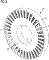
- FIG 3 shows a reinforcement 24 of the short-circuit ring 6 from the view of the laminated core 5.
- the side surface 26 facing the laminated core 5 has openings 11 which serve to accommodate the electrical conductors, be it for the casting process and/or inserted as shaped rods. There are no recesses for ventilation on this side surface 26.
- FIG 4 shows a partial section of the reinforcement 24, the outer contour 10, as well as the inner contour 9 and the grid structure 14 present within these contours and the side surfaces 25, 26.
- This grid structure 14 has a supporting function of the conductor material within the short-circuit ring 6, especially at high speeds.
- the lattice structure 14 shown there has webs 20 which are brought together at nodes 21.
- the basic structure is constructed as follows: Starting from the inside of the inner contour 9, radial webs 20 extend to the inside of the outer contour 10, with further webs 20 being provided both in the circumferential direction and in the radial and/or axial direction. At the crossing points of the webs 20 there are nodes 21 which serve to stabilize the entire lattice structure 14 within the reinforcement 24.
- the reinforcement 24 is manufactured using additive manufacturing processes due to the complex, in particular microscale, lattice structure 14. Also known as 3D printing process Manufacturing methods allow complicated, one-piece reinforcements to be produced from one or more tensile materials such as steel and/or titanium.
- the electrically conductive material for example liquid aluminum, is now introduced into the reinforcement 24 using a die-casting process, which then occupies the volume not occupied by the grid structure 14. This results in a structure of the conductor material according to FIG 5 , which shows a "half" short-circuit ring 6, without the supporting grid structure 14.
- FIG 7 shows in a further embodiment, which is not the subject of the invention, the formation of a different type of lattice structure 14 in which individual deep-drawn sheets of the same or different structure arranged axially one behind the other generate a lattice structure.
- the inner contour 9 is generated by placing the individual sheets axially one behind the other by means of a centering edge 19, as is the outer contour 10.
- This also results in a reinforcement 24 which has an outer contour 10, an inner contour 9, as well as the side surfaces 25 and 26.
- the lattice structure 14 within this reinforcement is manufactured using a stamping and deep-drawing process and is therefore designed differently in terms of structure, but has the same properties as the reinforcement 24 described above.
- FIG 8 can be seen where in an exploded view the side surfaces 25, 26 were referred to as a deep-drawn sheet on the outside and as a deep-drawn sheet on the inside.
- FIG 9 shows a reinforcement 24 of the short-circuit ring 6 composed of deep-drawn sheets, which also have ventilation recesses 8 and, at least in the case of a reinforcement, injection channels 13.
- the squirrel cage rotor 6 thus has at least one reinforcement 24 made of tensile material on each of its end faces. Within the reinforcement 24 and in at least parts of the groove spaces, conductive material is present by means of a casting process.
- prefabricated conductor bars for example made of copper, were previously positioned in these groove spaces and protrude axially from the end faces of the laminated core 5 into the reinforcement 24.
- the remaining cavities in the grooves and the reinforcement 24 are occupied by a conductive casting compound such as aluminum or copper in the further manufacturing process.
- the squirrel-cage rotor 6 according to the invention is particularly suitable for applications of an asynchronous machine in the high-speed range, i.e. at rotational speeds of peripheral speeds on the rotor of up to 200 m/s, such as in drives in vehicle technology, such as in e-cars, but also in machine tool technology or for pump and compressor drives.
Landscapes
- Engineering & Computer Science (AREA)
- Power Engineering (AREA)
- Induction Machinery (AREA)
- Manufacture Of Motors, Generators (AREA)
Claims (10)
- Rotor (3) en court-circuit d'une machine (1) asynchrone comprenant des conducteurs électriques, qui sont prévus dans des encoches s'étendant sensiblement axialement d'un paquet (5) de tôle,- dans lequel, il est prévu, sur chaque côté frontal du paquet (5) de tôle, au moins un anneau (6) de court-circuit, qui relie électriquement au moins un nombre donné à l'avance des conducteurs électriques,- dans lequel l'anneau (6) de court-circuit a un blindage (24) en un matériau relativement très résistant,- dans lequel le blindage (24) a un contour (10) extérieur, un contour (9) intérieur et des surfaces (25, 26) latérales,- dans lequel le blindage (24) est constitué fermé sur le pourtour extérieur et sur le pourtour intérieur,- dans lequel les surfaces (25) latérales sont réalisées fermées du côté non tourné vers le paquet (5) de tôle ou ont des ouvertures (8) de dégazage pendant le processus de coulée sous pression,- dans lequel il est prévu, sur la face (25) latérale du côté, non tourné vers le paquet (5) de tôle, des canaux (13) d'injection, afin de pouvoir faire entrer le matériau liquide électrique dans le blindage (24), tout comme dans les espaces d'encoche du paquet (5) de tôle,- dans lequel il est prévu sur des surfaces (26) latérales dans la direction du paquet (5) de tôle des évidements pour les conducteurs électriques,- dans lequel il est prévu une structure (24) en grille de barrettes radiales s'étendant de la face intérieure du contour (9) intérieur à la face intérieure du contour (10) extérieur,- dans lequel il est prévu d'autres barrettes (20), tant dans la direction périphérique qu'également dans la direction radiale ou axiale,- dans lequel il y a, aux points d'intersection des barrettes (20), des noeuds, qui servent à la stabilisation de toute la structure (14) en grille au sein du blindage (24).
- Rotor (3) en court-circuit suivant la revendication 1, caractérisé en ce que les conducteurs électriques dans l'encoche sont en aluminium et/ou en cuivre.
- Rotor (3) en court-circuit suivant l'une des revendications précédentes, caractérisé en ce que le blindage (24) a un contour presque fermé avec une structure (14) intérieure en grille.
- Rotor (3) en court-circuit suivant la revendication 3, caractérisé en ce que la structure (14) en grille se trouve au moins dans la partie extérieure radialement de l'anneau (6) de court-circuit.
- Rotor (3) en court-circuit suivant l'une des revendications précédentes, caractérisé en ce que le blindage (24) a été fabriqué par fabrication additive.
- Machine (1) dynamoélectrique, en particulier machine asynchrone, ayant un rotor (3) en court-circuit suivant l'une des revendications précédentes.
- Machine-outil, E-car, entraînement de compresseur ou entraînement de pompe ayant au moins une machine (1) dynamoélectrique suivant la revendication 6.
- Procédé de fabrication d'un rotor (3) en court-circuit par les stades suivants :- estampage et mise en paquet d'un paquet (5) de tôle du rotor (3) en court-circuit,- immobilisation d'un blindage (24) approprié sur les côtés frontaux du paquet (5) de tôle,- dans lequel le blindage (24) est en un matériau relativement très résistant,- dans lequel le blindage (24) a un contour (10) extérieur, un contour (9) intérieur et des surfaces (25, 26) latérales,- dans lequel le blindage (24) est constitué fermé sur le pourtour extérieur et sur le pourtour intérieur,- dans lequel les surfaces (25) latérales sont réalisées fermées, du côté non tourné vers le paquet (5) de tôle, ou ont des ouvertures (8) de dégazage pendant l'opération de coulée sous pression,- dans lequel il est prévu, sur les surfaces (25) latérales, du côté non tourné vers le paquet (5) de tôle, des canaux (13) d'injection, afin de pouvoir faire entrer la matière liquide électrique dans le blindage (24) tout comme également dans les espaces d'encoches du paquet (5) de tôle,- dans lequel il est prévu, sur les surfaces (26) latérales dans la direction du paquet (5) de tôle, des évidements pour les conducteurs électriques,- dans lequel la structure (24) en grille a des barrettes s'étendant radialement de la face intérieure du contour (9) intérieur à la face intérieure du contour (10) extérieur,- dans lequel d'autres barrettes (20) sont prévues, tant dans la direction périphérique, qu'également dans la direction radiale et/ou axiale,- dans lequel il y a aux points d'intersection des barrettes (20), des noeuds, qui servent à la stabilisation de toute la structure (14) de grille au sein du blindage (24),- dans lequel on injecte une composition de coulée conductrice par au moins un canal (13) d'injection dans les blindages (24) et les espaces d'encoches du paquet (5) de tôle.
- Procédé de fabrication d'un rotor (3) en court-circuit suivant la revendication 8, caractérisé en ce que l'on insère des barreaux conducteurs de l'électricité dans les espaces d'encoches avant l'injection de la composition de coulée.
- Procédé de fabrication d'un rotor (3) en court-circuit suivant la revendication 9, caractérisé en ce qu'au moins certains barreaux conducteurs dépassent axialement des côtés frontaux du paquet (5) de tôle jusque dans le blindage (24).
Applications Claiming Priority (2)
| Application Number | Priority Date | Filing Date | Title |
|---|---|---|---|
| EP16185511.9A EP3288159A1 (fr) | 2016-08-24 | 2016-08-24 | Rotor en court-circuit en particulier pour dispositifs a haut regime |
| PCT/EP2017/069775 WO2018036787A1 (fr) | 2016-08-24 | 2017-08-04 | Rotor en court-circuit en particulier pour les grandes vitesses de rotation |
Publications (2)
| Publication Number | Publication Date |
|---|---|
| EP3469694A1 EP3469694A1 (fr) | 2019-04-17 |
| EP3469694B1 true EP3469694B1 (fr) | 2023-09-27 |
Family
ID=56799355
Family Applications (2)
| Application Number | Title | Priority Date | Filing Date |
|---|---|---|---|
| EP16185511.9A Withdrawn EP3288159A1 (fr) | 2016-08-24 | 2016-08-24 | Rotor en court-circuit en particulier pour dispositifs a haut regime |
| EP17752070.7A Active EP3469694B1 (fr) | 2016-08-24 | 2017-08-04 | Rotor en court-circuit en particulier pour dispositifs a haut regime |
Family Applications Before (1)
| Application Number | Title | Priority Date | Filing Date |
|---|---|---|---|
| EP16185511.9A Withdrawn EP3288159A1 (fr) | 2016-08-24 | 2016-08-24 | Rotor en court-circuit en particulier pour dispositifs a haut regime |
Country Status (4)
| Country | Link |
|---|---|
| US (1) | US11183909B2 (fr) |
| EP (2) | EP3288159A1 (fr) |
| CN (1) | CN109478831B (fr) |
| WO (1) | WO2018036787A1 (fr) |
Families Citing this family (8)
| Publication number | Priority date | Publication date | Assignee | Title |
|---|---|---|---|---|
| EP3288159A1 (fr) | 2016-08-24 | 2018-02-28 | Siemens Aktiengesellschaft | Rotor en court-circuit en particulier pour dispositifs a haut regime |
| EP3578312A1 (fr) * | 2018-06-06 | 2019-12-11 | HILTI Aktiengesellschaft | Appareil de pose |
| EP3578308A1 (fr) * | 2018-06-06 | 2019-12-11 | HILTI Aktiengesellschaft | Appareil de pose |
| EP3578305A1 (fr) * | 2018-06-06 | 2019-12-11 | HILTI Aktiengesellschaft | Appareil de pose |
| EP3578313A1 (fr) * | 2018-06-06 | 2019-12-11 | HILTI Aktiengesellschaft | Appareil de pose |
| EP3578316A1 (fr) * | 2018-06-06 | 2019-12-11 | HILTI Aktiengesellschaft | Appareil de pose |
| EP3961880A1 (fr) * | 2020-08-31 | 2022-03-02 | Siemens Aktiengesellschaft | Partie active d'une machine électrique pourvue de conducteur imprimé |
| JP7507716B2 (ja) * | 2021-03-31 | 2024-06-28 | 三菱重工業株式会社 | 電動機用ロータ、及び電動機 |
Citations (2)
| Publication number | Priority date | Publication date | Assignee | Title |
|---|---|---|---|---|
| CA2980194A1 (fr) * | 2014-03-21 | 2015-09-24 | Evans Electric Pty Limited | Rotor pour machine electrique |
| DE102015202004A1 (de) * | 2015-02-05 | 2016-08-11 | Robert Bosch Gmbh | Käfigläuferrotor mit stabilem Kurzschlussring für eine elektrische Asynchronmaschine sowie Verfahren zum Fertigen desselben |
Family Cites Families (17)
| Publication number | Priority date | Publication date | Assignee | Title |
|---|---|---|---|---|
| EP0196457A1 (fr) * | 1985-04-01 | 1986-10-08 | Saia Ag | Moteur pas à pas monophasé |
| DE19919899C1 (de) * | 1999-03-15 | 2000-09-07 | Loher Ag | Kurzschlußkäfig für eine elektrische Maschine, vorzugsweise Asynchronmaschine |
| DE102005030798A1 (de) | 2005-06-29 | 2007-01-04 | Siemens Ag | Läufer einer Asynchronmaschine |
| US20070075603A1 (en) * | 2005-09-30 | 2007-04-05 | Whiddon Richard M | Labyrinthine end disk rotor |
| US8319388B2 (en) | 2008-01-25 | 2012-11-27 | Mitsubishi Electric Corporation | Induction motor and hermetic compressor |
| US20100171387A1 (en) * | 2009-01-07 | 2010-07-08 | Bae Systems Controls Inc. | Die Cast Rotor With Steel End Rings to Contain Aluminum |
| US20130181570A1 (en) | 2010-05-27 | 2013-07-18 | Yazaki Corporation | Rotor of induction motor, and induction motor using same |
| US8587174B2 (en) * | 2010-11-24 | 2013-11-19 | GM Global Technology Operations LLC | Rotor assembly and method of manufacturing a rotor assembly |
| US8424188B2 (en) | 2011-02-23 | 2013-04-23 | GM Global Technology Operations LLC | Method of manufacturing an end ring over pre-formed conductor bars of a rotor for an electric device |
| JP5155423B2 (ja) | 2011-04-04 | 2013-03-06 | ファナック株式会社 | かご形回転子及びその製造方法 |
| EP2549630B1 (fr) * | 2011-07-22 | 2013-10-02 | Siemens Aktiengesellschaft | Cage d'écureuil d'une machine asynchrone et procédé de fabrication d'une telle cage |
| JP5562307B2 (ja) * | 2011-08-30 | 2014-07-30 | 日立オートモティブシステムズ株式会社 | かご形回転子および回転電機 |
| US9419502B2 (en) * | 2012-08-03 | 2016-08-16 | Hamilton Sundstrand Corporation | Additive manufacturing of a component having a laminated stack of layers |
| DE102014208399A1 (de) | 2014-05-06 | 2015-11-12 | Siemens Aktiengesellschaft | Kurzschlussläufer für eine elektrische Maschine |
| DE102014210339A1 (de) * | 2014-06-02 | 2015-12-03 | Siemens Aktiengesellschaft | Käfigläufer einer Asynchronmaschine |
| CN204931903U (zh) * | 2015-08-14 | 2016-01-06 | 西安交通大学第二附属医院 | 一种下颈椎3d打印钛笼 |
| EP3288159A1 (fr) | 2016-08-24 | 2018-02-28 | Siemens Aktiengesellschaft | Rotor en court-circuit en particulier pour dispositifs a haut regime |
-
2016
- 2016-08-24 EP EP16185511.9A patent/EP3288159A1/fr not_active Withdrawn
-
2017
- 2017-08-04 EP EP17752070.7A patent/EP3469694B1/fr active Active
- 2017-08-04 US US16/327,748 patent/US11183909B2/en active Active
- 2017-08-04 WO PCT/EP2017/069775 patent/WO2018036787A1/fr unknown
- 2017-08-04 CN CN201780045771.4A patent/CN109478831B/zh active Active
Patent Citations (2)
| Publication number | Priority date | Publication date | Assignee | Title |
|---|---|---|---|---|
| CA2980194A1 (fr) * | 2014-03-21 | 2015-09-24 | Evans Electric Pty Limited | Rotor pour machine electrique |
| DE102015202004A1 (de) * | 2015-02-05 | 2016-08-11 | Robert Bosch Gmbh | Käfigläuferrotor mit stabilem Kurzschlussring für eine elektrische Asynchronmaschine sowie Verfahren zum Fertigen desselben |
Also Published As
| Publication number | Publication date |
|---|---|
| CN109478831B (zh) | 2021-12-10 |
| US20190229597A1 (en) | 2019-07-25 |
| US11183909B2 (en) | 2021-11-23 |
| WO2018036787A1 (fr) | 2018-03-01 |
| CN109478831A (zh) | 2019-03-15 |
| EP3288159A1 (fr) | 2018-02-28 |
| EP3469694A1 (fr) | 2019-04-17 |
Similar Documents
| Publication | Publication Date | Title |
|---|---|---|
| EP3469694B1 (fr) | Rotor en court-circuit en particulier pour dispositifs a haut regime | |
| EP2396872B1 (fr) | Rotor a cage | |
| EP2288004B1 (fr) | Cage d'écureuil dotée d'une tige de démarrage | |
| EP2592729B1 (fr) | Rotor d'une machine asynchrone doté d'un élément de retenue | |
| EP2577852B1 (fr) | Induit à cage d'écureuil pour une machine asynchrone et procédé de fabrication de l'induit à cage d'écureuil | |
| WO2014090694A1 (fr) | Induit à cage d'écureuil fiable | |
| EP3574574B1 (fr) | Procédé de fabrication d'un rotor à cage d'écureuil d'une machine asynchrone | |
| EP2885858A2 (fr) | Rotor à cage d'écureuil pour machine électrique | |
| WO2016055199A2 (fr) | Rotor à cage pour machine électrique asynchrone comportant des tirants qui stabilisent une bague de court-circuit | |
| WO2016055186A1 (fr) | Rotor à cage destiné à un moteur électrique asynchrone, muni d'un disque de support stabilisant la bague de court-circuit | |
| EP3577746B1 (fr) | Fabrication additive d'un rotor | |
| EP3574573B1 (fr) | Cage d'écureuil hybride | |
| AT509042A2 (de) | Rotor für asynchronmaschinen | |
| EP3145059A1 (fr) | Cage d'ecureuil | |
| DE102015224577A1 (de) | Rotor, Verfahren zum Herstellen eines Rotors, Asynchronmaschine und Fahrzeug | |
| DE102015202004A1 (de) | Käfigläuferrotor mit stabilem Kurzschlussring für eine elektrische Asynchronmaschine sowie Verfahren zum Fertigen desselben | |
| DE102016201048A1 (de) | Rotor, elektrische Maschine und Verfahren zur Herstellung | |
| EP3402058A1 (fr) | Rotor pour une machine électrique, machine électrique comprenant un tel rotor ainsi que procédé de fabrication d'un rotor | |
| EP3657635A1 (fr) | Rotor pour une machine asynchrone à géométrie de type barre optimisée en termes de pertes, machine asynchrone ainsi que procédé | |
| WO2023217783A1 (fr) | Rotor de moteur de cage d'écureuil et son procédé de fabrication | |
| EP3627661B1 (fr) | Induit à cage d'ecureuil et fabrication d'un induit à cage d'ecureuil | |
| EP3900156B1 (fr) | Noyau feuilleté pour une machine électrique | |
| DE102019123552A1 (de) | Verfahren zur Herstellung eines Rotors, Rotor sowie Asynchronmotor | |
| EP4436015A1 (fr) | Rotor d'un moteur à cage d'écureuil, moteur à cage d'écureuil comprenant un rotor et procédé de fabrication d'un rotor d'un moteur à cage d'écureuil | |
| DE102023201638A1 (de) | Rotor, Asynchronmaschine und Kraftfahrzeug |
Legal Events
| Date | Code | Title | Description |
|---|---|---|---|
| STAA | Information on the status of an ep patent application or granted ep patent |
Free format text: STATUS: UNKNOWN |
|
| STAA | Information on the status of an ep patent application or granted ep patent |
Free format text: STATUS: THE INTERNATIONAL PUBLICATION HAS BEEN MADE |
|
| PUAI | Public reference made under article 153(3) epc to a published international application that has entered the european phase |
Free format text: ORIGINAL CODE: 0009012 |
|
| STAA | Information on the status of an ep patent application or granted ep patent |
Free format text: STATUS: REQUEST FOR EXAMINATION WAS MADE |
|
| 17P | Request for examination filed |
Effective date: 20190110 |
|
| AK | Designated contracting states |
Kind code of ref document: A1 Designated state(s): AL AT BE BG CH CY CZ DE DK EE ES FI FR GB GR HR HU IE IS IT LI LT LU LV MC MK MT NL NO PL PT RO RS SE SI SK SM TR |
|
| AX | Request for extension of the european patent |
Extension state: BA ME |
|
| DAV | Request for validation of the european patent (deleted) | ||
| DAX | Request for extension of the european patent (deleted) | ||
| STAA | Information on the status of an ep patent application or granted ep patent |
Free format text: STATUS: EXAMINATION IS IN PROGRESS |
|
| 17Q | First examination report despatched |
Effective date: 20200113 |
|
| STAA | Information on the status of an ep patent application or granted ep patent |
Free format text: STATUS: EXAMINATION IS IN PROGRESS |
|
| STAA | Information on the status of an ep patent application or granted ep patent |
Free format text: STATUS: EXAMINATION IS IN PROGRESS |
|
| GRAP | Despatch of communication of intention to grant a patent |
Free format text: ORIGINAL CODE: EPIDOSNIGR1 |
|
| STAA | Information on the status of an ep patent application or granted ep patent |
Free format text: STATUS: GRANT OF PATENT IS INTENDED |
|
| INTG | Intention to grant announced |
Effective date: 20230426 |
|
| GRAS | Grant fee paid |
Free format text: ORIGINAL CODE: EPIDOSNIGR3 |
|
| GRAA | (expected) grant |
Free format text: ORIGINAL CODE: 0009210 |
|
| STAA | Information on the status of an ep patent application or granted ep patent |
Free format text: STATUS: THE PATENT HAS BEEN GRANTED |
|
| AK | Designated contracting states |
Kind code of ref document: B1 Designated state(s): AL AT BE BG CH CY CZ DE DK EE ES FI FR GB GR HR HU IE IS IT LI LT LU LV MC MK MT NL NO PL PT RO RS SE SI SK SM TR |
|
| REG | Reference to a national code |
Ref country code: GB Ref legal event code: FG4D Free format text: NOT ENGLISH |
|
| REG | Reference to a national code |
Ref country code: CH Ref legal event code: EP |
|
| P01 | Opt-out of the competence of the unified patent court (upc) registered |
Effective date: 20230907 |
|
| REG | Reference to a national code |
Ref country code: DE Ref legal event code: R096 Ref document number: 502017015426 Country of ref document: DE |
|
| REG | Reference to a national code |
Ref country code: IE Ref legal event code: FG4D Free format text: LANGUAGE OF EP DOCUMENT: GERMAN |
|
| RAP2 | Party data changed (patent owner data changed or rights of a patent transferred) |
Owner name: INNOMOTICS GMBH |
|
| REG | Reference to a national code |
Ref country code: LT Ref legal event code: MG9D |
|
| PG25 | Lapsed in a contracting state [announced via postgrant information from national office to epo] |
Ref country code: GR Free format text: LAPSE BECAUSE OF FAILURE TO SUBMIT A TRANSLATION OF THE DESCRIPTION OR TO PAY THE FEE WITHIN THE PRESCRIBED TIME-LIMIT Effective date: 20231228 |
|
| PG25 | Lapsed in a contracting state [announced via postgrant information from national office to epo] |
Ref country code: SE Free format text: LAPSE BECAUSE OF FAILURE TO SUBMIT A TRANSLATION OF THE DESCRIPTION OR TO PAY THE FEE WITHIN THE PRESCRIBED TIME-LIMIT Effective date: 20230927 Ref country code: RS Free format text: LAPSE BECAUSE OF FAILURE TO SUBMIT A TRANSLATION OF THE DESCRIPTION OR TO PAY THE FEE WITHIN THE PRESCRIBED TIME-LIMIT Effective date: 20230927 Ref country code: NO Free format text: LAPSE BECAUSE OF FAILURE TO SUBMIT A TRANSLATION OF THE DESCRIPTION OR TO PAY THE FEE WITHIN THE PRESCRIBED TIME-LIMIT Effective date: 20231227 Ref country code: LV Free format text: LAPSE BECAUSE OF FAILURE TO SUBMIT A TRANSLATION OF THE DESCRIPTION OR TO PAY THE FEE WITHIN THE PRESCRIBED TIME-LIMIT Effective date: 20230927 Ref country code: LT Free format text: LAPSE BECAUSE OF FAILURE TO SUBMIT A TRANSLATION OF THE DESCRIPTION OR TO PAY THE FEE WITHIN THE PRESCRIBED TIME-LIMIT Effective date: 20230927 Ref country code: HR Free format text: LAPSE BECAUSE OF FAILURE TO SUBMIT A TRANSLATION OF THE DESCRIPTION OR TO PAY THE FEE WITHIN THE PRESCRIBED TIME-LIMIT Effective date: 20230927 Ref country code: GR Free format text: LAPSE BECAUSE OF FAILURE TO SUBMIT A TRANSLATION OF THE DESCRIPTION OR TO PAY THE FEE WITHIN THE PRESCRIBED TIME-LIMIT Effective date: 20231228 Ref country code: FI Free format text: LAPSE BECAUSE OF FAILURE TO SUBMIT A TRANSLATION OF THE DESCRIPTION OR TO PAY THE FEE WITHIN THE PRESCRIBED TIME-LIMIT Effective date: 20230927 |
|
| REG | Reference to a national code |
Ref country code: NL Ref legal event code: MP Effective date: 20230927 |
|
| PG25 | Lapsed in a contracting state [announced via postgrant information from national office to epo] |
Ref country code: NL Free format text: LAPSE BECAUSE OF FAILURE TO SUBMIT A TRANSLATION OF THE DESCRIPTION OR TO PAY THE FEE WITHIN THE PRESCRIBED TIME-LIMIT Effective date: 20230927 |
|
| PG25 | Lapsed in a contracting state [announced via postgrant information from national office to epo] |
Ref country code: IS Free format text: LAPSE BECAUSE OF FAILURE TO SUBMIT A TRANSLATION OF THE DESCRIPTION OR TO PAY THE FEE WITHIN THE PRESCRIBED TIME-LIMIT Effective date: 20240127 |
|
| REG | Reference to a national code |
Ref country code: DE Ref legal event code: R081 Ref document number: 502017015426 Country of ref document: DE Owner name: INNOMOTICS GMBH, DE Free format text: FORMER OWNER: SIEMENS AKTIENGESELLSCHAFT, 80333 MUENCHEN, DE |
|
| PG25 | Lapsed in a contracting state [announced via postgrant information from national office to epo] |
Ref country code: ES Free format text: LAPSE BECAUSE OF FAILURE TO SUBMIT A TRANSLATION OF THE DESCRIPTION OR TO PAY THE FEE WITHIN THE PRESCRIBED TIME-LIMIT Effective date: 20230927 |
|
| PG25 | Lapsed in a contracting state [announced via postgrant information from national office to epo] |
Ref country code: SM Free format text: LAPSE BECAUSE OF FAILURE TO SUBMIT A TRANSLATION OF THE DESCRIPTION OR TO PAY THE FEE WITHIN THE PRESCRIBED TIME-LIMIT Effective date: 20230927 Ref country code: RO Free format text: LAPSE BECAUSE OF FAILURE TO SUBMIT A TRANSLATION OF THE DESCRIPTION OR TO PAY THE FEE WITHIN THE PRESCRIBED TIME-LIMIT Effective date: 20230927 Ref country code: IS Free format text: LAPSE BECAUSE OF FAILURE TO SUBMIT A TRANSLATION OF THE DESCRIPTION OR TO PAY THE FEE WITHIN THE PRESCRIBED TIME-LIMIT Effective date: 20240127 Ref country code: ES Free format text: LAPSE BECAUSE OF FAILURE TO SUBMIT A TRANSLATION OF THE DESCRIPTION OR TO PAY THE FEE WITHIN THE PRESCRIBED TIME-LIMIT Effective date: 20230927 Ref country code: EE Free format text: LAPSE BECAUSE OF FAILURE TO SUBMIT A TRANSLATION OF THE DESCRIPTION OR TO PAY THE FEE WITHIN THE PRESCRIBED TIME-LIMIT Effective date: 20230927 Ref country code: CZ Free format text: LAPSE BECAUSE OF FAILURE TO SUBMIT A TRANSLATION OF THE DESCRIPTION OR TO PAY THE FEE WITHIN THE PRESCRIBED TIME-LIMIT Effective date: 20230927 Ref country code: PT Free format text: LAPSE BECAUSE OF FAILURE TO SUBMIT A TRANSLATION OF THE DESCRIPTION OR TO PAY THE FEE WITHIN THE PRESCRIBED TIME-LIMIT Effective date: 20240129 Ref country code: SK Free format text: LAPSE BECAUSE OF FAILURE TO SUBMIT A TRANSLATION OF THE DESCRIPTION OR TO PAY THE FEE WITHIN THE PRESCRIBED TIME-LIMIT Effective date: 20230927 |
|
| PG25 | Lapsed in a contracting state [announced via postgrant information from national office to epo] |
Ref country code: PL Free format text: LAPSE BECAUSE OF FAILURE TO SUBMIT A TRANSLATION OF THE DESCRIPTION OR TO PAY THE FEE WITHIN THE PRESCRIBED TIME-LIMIT Effective date: 20230927 |
|
| REG | Reference to a national code |
Ref country code: DE Ref legal event code: R097 Ref document number: 502017015426 Country of ref document: DE |
|
| PG25 | Lapsed in a contracting state [announced via postgrant information from national office to epo] |
Ref country code: DK Free format text: LAPSE BECAUSE OF FAILURE TO SUBMIT A TRANSLATION OF THE DESCRIPTION OR TO PAY THE FEE WITHIN THE PRESCRIBED TIME-LIMIT Effective date: 20230927 |
|
| PG25 | Lapsed in a contracting state [announced via postgrant information from national office to epo] |
Ref country code: DK Free format text: LAPSE BECAUSE OF FAILURE TO SUBMIT A TRANSLATION OF THE DESCRIPTION OR TO PAY THE FEE WITHIN THE PRESCRIBED TIME-LIMIT Effective date: 20230927 |
|
| PLBE | No opposition filed within time limit |
Free format text: ORIGINAL CODE: 0009261 |
|
| STAA | Information on the status of an ep patent application or granted ep patent |
Free format text: STATUS: NO OPPOSITION FILED WITHIN TIME LIMIT |
|
| 26N | No opposition filed |
Effective date: 20240628 |
|
| PG25 | Lapsed in a contracting state [announced via postgrant information from national office to epo] |
Ref country code: SI Free format text: LAPSE BECAUSE OF FAILURE TO SUBMIT A TRANSLATION OF THE DESCRIPTION OR TO PAY THE FEE WITHIN THE PRESCRIBED TIME-LIMIT Effective date: 20230927 |
|
| PG25 | Lapsed in a contracting state [announced via postgrant information from national office to epo] |
Ref country code: SI Free format text: LAPSE BECAUSE OF FAILURE TO SUBMIT A TRANSLATION OF THE DESCRIPTION OR TO PAY THE FEE WITHIN THE PRESCRIBED TIME-LIMIT Effective date: 20230927 |
|
| PGFP | Annual fee paid to national office [announced via postgrant information from national office to epo] |
Ref country code: IT Payment date: 20240828 Year of fee payment: 8 |