EP3469694B1 - Bypass rotor in particular for high rotational speeds - Google Patents
Bypass rotor in particular for high rotational speeds Download PDFInfo
- Publication number
- EP3469694B1 EP3469694B1 EP17752070.7A EP17752070A EP3469694B1 EP 3469694 B1 EP3469694 B1 EP 3469694B1 EP 17752070 A EP17752070 A EP 17752070A EP 3469694 B1 EP3469694 B1 EP 3469694B1
- Authority
- EP
- European Patent Office
- Prior art keywords
- reinforcement
- laminated core
- squirrel
- cage rotor
- lattice structure
- Prior art date
- Legal status (The legal status is an assumption and is not a legal conclusion. Google has not performed a legal analysis and makes no representation as to the accuracy of the status listed.)
- Active
Links
- 230000002787 reinforcement Effects 0.000 claims description 53
- 239000004020 conductor Substances 0.000 claims description 18
- 229910052782 aluminium Inorganic materials 0.000 claims description 17
- XAGFODPZIPBFFR-UHFFFAOYSA-N aluminium Chemical compound [Al] XAGFODPZIPBFFR-UHFFFAOYSA-N 0.000 claims description 17
- 238000005266 casting Methods 0.000 claims description 17
- 238000004519 manufacturing process Methods 0.000 claims description 17
- 239000000463 material Substances 0.000 claims description 16
- 238000000034 method Methods 0.000 claims description 13
- 239000010949 copper Substances 0.000 claims description 12
- RYGMFSIKBFXOCR-UHFFFAOYSA-N Copper Chemical compound [Cu] RYGMFSIKBFXOCR-UHFFFAOYSA-N 0.000 claims description 11
- 229910052802 copper Inorganic materials 0.000 claims description 11
- 238000004512 die casting Methods 0.000 claims description 9
- 238000002347 injection Methods 0.000 claims description 9
- 239000007924 injection Substances 0.000 claims description 9
- 150000001875 compounds Chemical class 0.000 claims description 7
- 239000000654 additive Substances 0.000 claims description 3
- 230000000996 additive effect Effects 0.000 claims description 3
- 238000007872 degassing Methods 0.000 claims description 3
- 238000004806 packaging method and process Methods 0.000 claims description 2
- 238000004080 punching Methods 0.000 claims description 2
- 239000012530 fluid Substances 0.000 claims 2
- 239000004411 aluminium Substances 0.000 claims 1
- 241000555745 Sciuridae Species 0.000 description 24
- 239000000956 alloy Substances 0.000 description 9
- 229910045601 alloy Inorganic materials 0.000 description 9
- 230000002093 peripheral effect Effects 0.000 description 5
- 238000005516 engineering process Methods 0.000 description 4
- 238000009423 ventilation Methods 0.000 description 4
- 238000010146 3D printing Methods 0.000 description 2
- 229910000831 Steel Inorganic materials 0.000 description 2
- RTAQQCXQSZGOHL-UHFFFAOYSA-N Titanium Chemical compound [Ti] RTAQQCXQSZGOHL-UHFFFAOYSA-N 0.000 description 2
- 230000015572 biosynthetic process Effects 0.000 description 2
- 239000000155 melt Substances 0.000 description 2
- 230000006641 stabilisation Effects 0.000 description 2
- 238000011105 stabilization Methods 0.000 description 2
- 239000010959 steel Substances 0.000 description 2
- 239000010936 titanium Substances 0.000 description 2
- 229910052719 titanium Inorganic materials 0.000 description 2
- 238000004804 winding Methods 0.000 description 2
- XUIMIQQOPSSXEZ-UHFFFAOYSA-N Silicon Chemical compound [Si] XUIMIQQOPSSXEZ-UHFFFAOYSA-N 0.000 description 1
- 238000005275 alloying Methods 0.000 description 1
- 238000004458 analytical method Methods 0.000 description 1
- 239000002131 composite material Substances 0.000 description 1
- 238000006073 displacement reaction Methods 0.000 description 1
- 230000000694 effects Effects 0.000 description 1
- 239000011261 inert gas Substances 0.000 description 1
- 230000003993 interaction Effects 0.000 description 1
- 239000007788 liquid Substances 0.000 description 1
- 239000011344 liquid material Substances 0.000 description 1
- WPBNNNQJVZRUHP-UHFFFAOYSA-L manganese(2+);methyl n-[[2-(methoxycarbonylcarbamothioylamino)phenyl]carbamothioyl]carbamate;n-[2-(sulfidocarbothioylamino)ethyl]carbamodithioate Chemical compound [Mn+2].[S-]C(=S)NCCNC([S-])=S.COC(=O)NC(=S)NC1=CC=CC=C1NC(=S)NC(=O)OC WPBNNNQJVZRUHP-UHFFFAOYSA-L 0.000 description 1
- 238000002844 melting Methods 0.000 description 1
- 230000008018 melting Effects 0.000 description 1
- 229910052751 metal Inorganic materials 0.000 description 1
- 239000002184 metal Substances 0.000 description 1
- 150000002739 metals Chemical class 0.000 description 1
- 239000002244 precipitate Substances 0.000 description 1
- 230000003014 reinforcing effect Effects 0.000 description 1
- 229910052710 silicon Inorganic materials 0.000 description 1
- 239000010703 silicon Substances 0.000 description 1
- 229910052712 strontium Inorganic materials 0.000 description 1
- CIOAGBVUUVVLOB-UHFFFAOYSA-N strontium atom Chemical compound [Sr] CIOAGBVUUVVLOB-UHFFFAOYSA-N 0.000 description 1
- 239000011800 void material Substances 0.000 description 1
Images


Classifications
-
- H—ELECTRICITY
- H02—GENERATION; CONVERSION OR DISTRIBUTION OF ELECTRIC POWER
- H02K—DYNAMO-ELECTRIC MACHINES
- H02K17/00—Asynchronous induction motors; Asynchronous induction generators
- H02K17/02—Asynchronous induction motors
- H02K17/16—Asynchronous induction motors having rotors with internally short-circuited windings, e.g. cage rotors
- H02K17/165—Asynchronous induction motors having rotors with internally short-circuited windings, e.g. cage rotors characterised by the squirrel-cage or other short-circuited windings
-
- H—ELECTRICITY
- H02—GENERATION; CONVERSION OR DISTRIBUTION OF ELECTRIC POWER
- H02K—DYNAMO-ELECTRIC MACHINES
- H02K15/00—Methods or apparatus specially adapted for manufacturing, assembling, maintaining or repairing of dynamo-electric machines
- H02K15/0012—Manufacturing cage rotors
-
- H—ELECTRICITY
- H02—GENERATION; CONVERSION OR DISTRIBUTION OF ELECTRIC POWER
- H02K—DYNAMO-ELECTRIC MACHINES
- H02K17/00—Asynchronous induction motors; Asynchronous induction generators
- H02K17/02—Asynchronous induction motors
- H02K17/16—Asynchronous induction motors having rotors with internally short-circuited windings, e.g. cage rotors
- H02K17/20—Asynchronous induction motors having rotors with internally short-circuited windings, e.g. cage rotors having deep-bar rotors
Definitions
- the invention relates to a squirrel cage rotor of an asynchronous machine with electrical conductors which are provided in essentially axially extending grooves of a laminated core, with at least one short-circuit ring being provided on each end face of the squirrel cage rotor, which electrically connects at least a predeterminable number of the electrical conductors.
- the invention further relates to a dynamoelectric machine with such a squirrel cage rotor and the use of such a dynamoelectric machine.
- the invention further relates to a method for producing such a squirrel cage rotor, in which a squirrel cage rotor is created by punching and packaging a laminated core.
- Squirrel-circuit rotors in dynamoelectric rotary asynchronous machines can usually be used up to a peripheral speed on the rotor of approx. 90 m/s. Higher speed suitability is only possible through special measures.
- the centrifugal force is quadratic of the speed, so that the material load, especially in the squirrel cage ring of a squirrel cage rotor, increases significantly with an increase in speed.
- the maximum permissible mechanical stresses in the short-circuit ring are up to approx. 80 N/mm 2 using common aluminum materials with a density of 2.7 kg/dm 3 .
- pure aluminum only has a tensile strength of a maximum of 20 N/mm 2 and is therefore not suitable as a casting compound for the desired high speed ranges.
- support rings made of a wide variety of materials are known on the outer diameter of a short-circuit ring.
- the disadvantage is that the ring only supports on the outside, but the material in the inner area of the short-circuit ring can flow due to the high centrifugal forces and mechanical stresses. This changes, among other things, the balancing values on the squirrel cage rotor, especially in the squirrel cage ring.
- the alloys in the melting crucible also precipitate alloy components, which can be strontium, silicon, manganese, etc., depending on the alloy.
- the short-circuit rings have a reinforcing ring that surrounds them radially on the outside and is supported on the shaft.
- the invention is based on the object of creating a dynamoelectric machine, in particular an asynchronous machine, with a squirrel-cage rotor, which is suitable for high peripheral speeds on the rotor, in particular up to 200 m/s, and with comparatively high efficiency a suitable drive for drive technology, etc. in vehicles as well as in machine tools.
- the problem can also be solved using a dynamoelectric machine, in particular an asynchronous machine with a squirrel-cage rotor according to the invention.
- the task at hand can also be solved using a machine tool, an e-car, a compressor drive or a pump drive with at least one dynamoelectric machine with a squirrel-cage rotor according to the invention.
- the above-mentioned disadvantages are avoided by reinforcement in the areas of the short-circuit ring.
- This reinforcement is preferred due to its structure manufactured in an additive manufacturing process (3D printing process) or using combined stamping and deep-drawn parts and inserted into the die-casting tool before pouring out the short-circuit cage in the laminated core.
- the reinforcement is designed to be as closed as possible on the outer and inner diameters, as well as on the end faces of the short-circuit ring.
- a fine mesh, a framework structure or lattice structure or a microscale structure is provided, which gives the short-circuit ring the necessary support during operation, but ensures sufficient efficiency of the asynchronous machine due to its comparatively low volume fraction of approximately 5 to 10%.
- the current flow is only slightly hindered.
- the invention is also suitable for a cage structure in which prefabricated copper rods are inserted into grooves in the laminated core, which advantageously protrude axially from the end faces of the laminated core and protrude into the reinforcement, so that through a subsequent casting process, for example with aluminum, these copper rods are now in aluminum are embedded, whereas the short-circuit ring is almost penetrated by aluminum and is kept at high speeds by the reinforcement.
- the reinforcement can also take on the function of the conductor rods during production to be fixed radially and uniformly inwards and outwards during die casting.
- a change or flow caused by high centrifugal forces on the outer or inner area of the short-circuit ring is thereby reliably avoided.
- the closed inner ring area of the reinforcement provides additional support, which counteracts the expansion of the short-circuit ring.
- a closed outer ring and a closed surface on at least one end face of the reinforcement also protect the outside area of the short-circuit ring from impermissible changes and expansion, especially in the high speed range.
- the inventive design of the squirrel cage rotor, in particular the squirrel cage rings, achieves a comparatively high level of efficiency, which cannot be achieved with pure aluminum as a casting compound and the required speeds.
- the idea according to the invention is suitable for all cages of squirrel-cage rotors, be they classic aluminum cages, hybrid cages, i.e. Cu conductor bars embedded in aluminum, with the short-circuit ring essentially consisting of aluminum or copper cages.
- the idea according to the invention is also suitable for special squirrel cage rotors (e.g. double or multiple squirrel cage rotors with cages insulated from each other).
- FIG 1 shows a basic representation of a longitudinal section of a dynamoelectric machine 1, in particular an asynchronous machine with a squirrel-cage rotor 3.
- the stator 2 has a winding system 4 which forms winding heads on the end faces of the stator 2.
- An electromagnetic interaction occurs between the stator 2 via an air gap 22 during operation of the asynchronous machine and squirrel cage rotor 3, which causes the squirrel cage rotor 3 to rotate about an axis 7.
- a laminated core 5 of the squirrel cage rotor 3 is connected to a shaft 23 in a rotationally fixed manner.
- the squirrel-cage rotor 3 has grooves that are almost axially parallel or slightly slanted in their axial course - up to approximately two groove spacings. In the grooves there are electrical conductors, not shown in detail in this illustration, which are connected in an electrically conductive manner to the short-circuit rings 6 of the squirrel-cage rotor 3.
- the squirrel cage ring 6 has a reinforcement 24 according to FIG 2 on, which consists of an outer contour 10, an inner contour 9 and the required side surfaces 25 for the outside and side surfaces 26 for the inside, i.e. facing towards the laminated core. Furthermore, recesses 8 for ventilation are provided on the outer contour 10 and/or on the side surface 25, 26, which improve the quality of the casting process during the die-casting process.
- injection channels 13 are provided on the side surface in order to be able to enter the electrical liquid material into the reinforcement as well as the groove spaces of the laminated core 5.
- FIG 2 also shows the reinforcement 24 of the short-circuit ring 6, which is positioned on the end faces of the laminated core 5 of the squirrel-cage rotor 3 before production, in particular the casting process.
- the injection channels 13 are round in this illustration, but depending on the requirements for the groove shape of the squirrel cage rotor 3, they can also be designed in a teardrop shape etc. in order to provide the largest possible flow channel during production. Depending on the requirements (current displacement effects) on the squirrel cage rotor 3, the groove shape can be rounded, teardrop-shaped, trapezoidal, etc.
- the reinforcement 24 does not necessarily have to rest directly on the front side of the laminated core 5.
- intermediate elements can be used, which can be removed after the casting process if necessary.
- the entire casting process takes place via one of the reinforcements 24, so that a material access opening is provided at least on one end face 26 of a reinforcement 24.
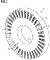
- FIG 3 shows a reinforcement 24 of the short-circuit ring 6 from the view of the laminated core 5.
- the side surface 26 facing the laminated core 5 has openings 11 which serve to accommodate the electrical conductors, be it for the casting process and/or inserted as shaped rods. There are no recesses for ventilation on this side surface 26.
- FIG 4 shows a partial section of the reinforcement 24, the outer contour 10, as well as the inner contour 9 and the grid structure 14 present within these contours and the side surfaces 25, 26.
- This grid structure 14 has a supporting function of the conductor material within the short-circuit ring 6, especially at high speeds.
- the lattice structure 14 shown there has webs 20 which are brought together at nodes 21.
- the basic structure is constructed as follows: Starting from the inside of the inner contour 9, radial webs 20 extend to the inside of the outer contour 10, with further webs 20 being provided both in the circumferential direction and in the radial and/or axial direction. At the crossing points of the webs 20 there are nodes 21 which serve to stabilize the entire lattice structure 14 within the reinforcement 24.
- the reinforcement 24 is manufactured using additive manufacturing processes due to the complex, in particular microscale, lattice structure 14. Also known as 3D printing process Manufacturing methods allow complicated, one-piece reinforcements to be produced from one or more tensile materials such as steel and/or titanium.
- the electrically conductive material for example liquid aluminum, is now introduced into the reinforcement 24 using a die-casting process, which then occupies the volume not occupied by the grid structure 14. This results in a structure of the conductor material according to FIG 5 , which shows a "half" short-circuit ring 6, without the supporting grid structure 14.
- FIG 7 shows in a further embodiment, which is not the subject of the invention, the formation of a different type of lattice structure 14 in which individual deep-drawn sheets of the same or different structure arranged axially one behind the other generate a lattice structure.
- the inner contour 9 is generated by placing the individual sheets axially one behind the other by means of a centering edge 19, as is the outer contour 10.
- This also results in a reinforcement 24 which has an outer contour 10, an inner contour 9, as well as the side surfaces 25 and 26.
- the lattice structure 14 within this reinforcement is manufactured using a stamping and deep-drawing process and is therefore designed differently in terms of structure, but has the same properties as the reinforcement 24 described above.
- FIG 8 can be seen where in an exploded view the side surfaces 25, 26 were referred to as a deep-drawn sheet on the outside and as a deep-drawn sheet on the inside.
- FIG 9 shows a reinforcement 24 of the short-circuit ring 6 composed of deep-drawn sheets, which also have ventilation recesses 8 and, at least in the case of a reinforcement, injection channels 13.
- the squirrel cage rotor 6 thus has at least one reinforcement 24 made of tensile material on each of its end faces. Within the reinforcement 24 and in at least parts of the groove spaces, conductive material is present by means of a casting process.
- prefabricated conductor bars for example made of copper, were previously positioned in these groove spaces and protrude axially from the end faces of the laminated core 5 into the reinforcement 24.
- the remaining cavities in the grooves and the reinforcement 24 are occupied by a conductive casting compound such as aluminum or copper in the further manufacturing process.
- the squirrel-cage rotor 6 according to the invention is particularly suitable for applications of an asynchronous machine in the high-speed range, i.e. at rotational speeds of peripheral speeds on the rotor of up to 200 m/s, such as in drives in vehicle technology, such as in e-cars, but also in machine tool technology or for pump and compressor drives.
Description
Die Erfindung betrifft einen Kurzschlussläufer/Käfigläufer einer Asynchronmaschine mit elektrischen Leitern, die in im Wesentlichen axial verlaufenden Nuten eines Blechpakets vorgesehen sind, wobei an jeder Stirnseite des Kurzschlussläufers zumindest ein Kurzschlussring vorgesehen ist, der zumindest eine vorgebbare Anzahl der elektrischen Leiter elektrisch verbindet. Weiterhin betrifft die Erfindung eine dynamoelektrische Maschine mit einem derartigen Kurzschlussläufer und die Verwendung einer derartigen dynamoelektrischen Maschine. Des Weiteren betrifft die Erfindung ein Verfahren zur Herstellung eines derartigen Kurzschlussläufers, in dem durch Stanzen und Paketieren eines Blechpakets ein Kurzschlussläufer geschaffen wird.The invention relates to a squirrel cage rotor of an asynchronous machine with electrical conductors which are provided in essentially axially extending grooves of a laminated core, with at least one short-circuit ring being provided on each end face of the squirrel cage rotor, which electrically connects at least a predeterminable number of the electrical conductors. The invention further relates to a dynamoelectric machine with such a squirrel cage rotor and the use of such a dynamoelectric machine. The invention further relates to a method for producing such a squirrel cage rotor, in which a squirrel cage rotor is created by punching and packaging a laminated core.
Kurzschlussläufer bei dynamoelektrischen rotatorischen Asynchronmaschinen können üblicherweise bis zu einer Umfangsgeschwindigkeit am Rotor von ca. 90 m/s eingesetzt werden. Eine höhere Drehzahleignung ist nur durch besondere Maßnahmen möglich.Squirrel-circuit rotors in dynamoelectric rotary asynchronous machines can usually be used up to a peripheral speed on the rotor of approx. 90 m/s. Higher speed suitability is only possible through special measures.
Aufgrund der Anforderungen nach immer kompakterer Bauweise bzw. Anwendungen von Direktantrieben zur Einsparung von Getrieben reichen nunmehr die Drehzahlanforderungen bis zu Umfangsgeschwindigkeiten am Rotor von 200 m/s, was z.B. bei einer Achshöhe 160 einer Drehzahl von ca. 25 000 U/min entspricht.Due to the requirements for ever more compact designs or applications of direct drives to save on gearboxes, the speed requirements now range up to peripheral speeds on the rotor of 200 m/s, which, for example, corresponds to a speed of approx. 25,000 rpm for an axle height of 160.
Die Fliehkraftbeanspruchung geht quadratisch zur Drehzahl ein, so dass die Materialbelastung, insbesondere im Kurzschlussring eines Kurzschlussläufers mit einer Drehzahlsteigerung erheblich zunimmt. Als maximal zulässige mechanische Spannungen im Kurzschlussring sind unter Verwendung von gängigen Aluminiummaterialien mit einer Dichte von 2,7 kg/dm3 bis zu ca. 80 N/mm2 möglich.The centrifugal force is quadratic of the speed, so that the material load, especially in the squirrel cage ring of a squirrel cage rotor, increases significantly with an increase in speed. The maximum permissible mechanical stresses in the short-circuit ring are up to approx. 80 N/mm 2 using common aluminum materials with a density of 2.7 kg/dm 3 .
Reines Aluminium hat jedoch bei üblichen Kurzschlussringtemperaturen im Bereich von 150 bis 200°C lediglich eine Zugfestigkeit von maximal 20 N/mm2 und scheidet damit als Vergussmasse für die angestrebten hohen Drehzahlbereiche aus.However, at usual short-circuit ring temperatures in the range of 150 to 200°C, pure aluminum only has a tensile strength of a maximum of 20 N/mm 2 and is therefore not suitable as a casting compound for the desired high speed ranges.
Kupfer ist aufgrund seiner Dichte von 8,9 kg/dm3 ebenfalls nicht für sehr hohe Drehzahlen geeignet, da bei den angestrebten Drehzahlen und den damit verbundenen Fliehkraftbeanspruchungen die Streckgrenze von Kupfer überschritten wird.Due to its density of 8.9 kg/dm 3 , copper is also not suitable for very high speeds, since the yield point of copper is exceeded at the desired speeds and the associated centrifugal force stresses.
Um außerdem eine hohe Effizienz von dynamoelektrischen Maschinen bereitzustellen, sind aber Materialien, wie reines Aluminium (elektrische Leitfähigkeit 36 m/Ω mm2) oder Kupfer (elektrische Leitfähigkeit 56 m/Ω·mm2) hervorragend geeignet. Mit den bekannten Legierungen von Aluminium und Kupfer sind Leitwerte der reinen Vergussmassen von Aluminium und Kupfer nicht zu erreichen.In order to also provide high efficiency of dynamoelectric machines, materials such as pure aluminum (electrical conductivity 36 m/Ω mm 2 ) or copper (electrical conductivity 56 m/Ω mm 2 ) are ideal. With the known alloys of aluminum and copper, conductivity values of pure aluminum and copper casting compounds cannot be achieved.
Um nunmehr derartige Drehzahlbereiche bei gleichzeitiger Effizienz einer dynamoelektrischen Maschine zu erhalten, sind Stützringe aus verschiedensten Materialien am Außendurchmesser eines Kurzschlussrings bekannt. Nachteilig dabei ist, dass der Ring nur nach außen abstützt, das Material im inneren Bereich des Kurzschlussringes jedoch aufgrund der hohen Fliehkräfte und mechanischen Spannungen fließen kann. Damit verändern sich u.a. die Wuchtwerte am Kurzschlussläufer, insbesondere im Kurzschlussring.In order to maintain such speed ranges while maintaining the efficiency of a dynamoelectric machine, support rings made of a wide variety of materials are known on the outer diameter of a short-circuit ring. The disadvantage is that the ring only supports on the outside, but the material in the inner area of the short-circuit ring can flow due to the high centrifugal forces and mechanical stresses. This changes, among other things, the balancing values on the squirrel cage rotor, especially in the squirrel cage ring.
Durch den Einsatz von hochfesten Legierungen mit erhöhter Zugfestigkeit bis ca. 80 N/mm2 wird ebenfalls versucht, diese hohen Drehzahlen zu erreichen. Nachteilig dabei ist, dass die elektrische Leitfähigkeit bei Werten von 20 bis 29 m/Ω·mm2 liegt und damit wesentlich niedriger angesiedelt ist als beim reinen Aluminium. Aufgrund der höheren Sprödigkeit dieser Legierungen ist auch die Dehnfähigkeit geringer, womit die Anfälligkeit bezüglich mechanischer Spannungsrisse am Kurzschlussring steigt.An attempt is also made to achieve these high speeds by using high-strength alloys with increased tensile strength up to approx. 80 N/mm 2 . The disadvantage here is that the electrical conductivity is between 20 and 29 m/Ω mm 2 and is therefore significantly lower than that of pure aluminum. Due to the greater brittleness of these alloys, the elasticity is also lower, which increases the susceptibility to mechanical stress cracks on the short-circuit ring.
Bei den Legierungen im Schmelztiegel kommt es außerdem zu Ausscheidungen von Legierungsbestandteilen, die je nach dem Strontium, Silicium, Mangan usw. sein können.The alloys in the melting crucible also precipitate alloy components, which can be strontium, silicon, manganese, etc., depending on the alloy.
Dadurch reduziert sich wiederum die Qualität der Schmelze im Bezug auf die elektrische Leitfähigkeit und die mechanische Festigkeitswerte. Die Prozesssicherheit und Prozessqualität des Druckgießens ist somit äußerst schwierig aufrecht zu erhalten. Dies geschieht z.B. durch ständige Analyse von Proben aus der Schmelze, sowie durch ein dadurch erforderliches Nachlegieren, indem die Legierungsbestandteile zugesetzt und durch Rührwerke möglichst gleichmäßig verteilt werden.This in turn reduces the quality of the melt in terms of electrical conductivity and mechanical strength values. The process reliability and process quality of die casting is therefore extremely difficult to maintain. This is done, for example, through constant analysis of samples from the melt, as well as through the necessary re-alloying by adding the alloy components and distributing them as evenly as possible using agitators.
Ein Vergießen unter Schutzgas bedeutet zudem erheblichen Mehraufwand. Besonders bei Antrieben in der Kfz-Industrie ist diese Methode aufgrund der geforderten Prozesssicherheiten mit sehr hohem Aufwand und Kosten verbunden und erreicht daher in der Asynchron- und Rotortechnik vergleichsweise wenig Akzeptanz.Casting under inert gas also means considerable additional effort. Especially for drives in the automotive industry, this method involves a lot of effort and costs due to the required process reliability and therefore achieves comparatively little acceptance in asynchronous and rotor technology.
Aus der
Aus der
Aus der
Aus der
Ausgehend davon liegt der Erfindung die Aufgabe zugrunde, eine dynamoelektrische Maschine zu schaffen, insbesondere eine Asynchronmaschine, mit Kurzschlussläufer, die für hohe Umfangsgeschwindigkeiten am Rotor geeignet ist, insbesondere bis zu 200 m/s und bei vergleichsweise hoher Effizienz einen geeigneten Antrieb für die Antriebstechnik u.a. in Fahrzeugen als auch bei Werkzeugmaschinen bietet.Based on this, the invention is based on the object of creating a dynamoelectric machine, in particular an asynchronous machine, with a squirrel-cage rotor, which is suitable for high peripheral speeds on the rotor, in particular up to 200 m/s, and with comparatively high efficiency a suitable drive for drive technology, etc. in vehicles as well as in machine tools.
Die Lösung der gestellten Aufgabe gelingt durch einen Kurzschlussläufer einer Asynchronmaschine nach Anspruch 1.The problem is solved using a squirrel-cage rotor of an asynchronous machine according to
Die Lösung der gestellten Aufgabe gelingt auch durch eine dynamoelektrische Maschine, insbesondere Asynchronmaschine mit einem erfindungsgemäßen Kurzschlussläufer.The problem can also be solved using a dynamoelectric machine, in particular an asynchronous machine with a squirrel-cage rotor according to the invention.
Die Lösung der gestellten Aufgabe gelingt auch durch eine Werkzeugmaschine, einen E-Car, einen Kompressorantrieb oder einen Pumpenantrieb mit zumindest einer dynamoelektrischen Maschine mit einem erfindungsgemäßen Kurzschlussläufer.The task at hand can also be solved using a machine tool, an e-car, a compressor drive or a pump drive with at least one dynamoelectric machine with a squirrel-cage rotor according to the invention.
Die Lösung der gestellten Aufgabe gelingt ebenfalls durch ein Verfahren zur Herstellung eines Kurzschlussläufers nach Anspruch 8.The problem is also solved by a method for producing a squirrel-cage rotor according to
Die oben genannten Nachteile werden erfindungsgemäß durch eine Armierung in den Bereichen des Kurzschlussringes vermieden. Diese Armierung wird aufgrund seiner Struktur vorzugsweise in einem Additiv-Manufacturing-Verfahren (3D-Druck-Verfahren) oder mittels kombinierter Stanz-Tiefziehteile angefertigt und vor dem Ausgießen des Kurzschlusskäfigs im Blechpaket in das Druckgießwerkzeug eingelegt.According to the invention, the above-mentioned disadvantages are avoided by reinforcement in the areas of the short-circuit ring. This reinforcement is preferred due to its structure manufactured in an additive manufacturing process (3D printing process) or using combined stamping and deep-drawn parts and inserted into the die-casting tool before pouring out the short-circuit cage in the laminated core.
Damit können nun für die Armierung Metalle mit sehr hoher Zugfestigkeit verwendet werden, wie z.B. Titan, Stahl. Die Armierung ist am Außen- und am Innendurchmesser, als auch auf den Stirnseiten des Kurzschlussringes möglichst geschlossen ausgebildet. Dazwischen ist ein feines Geflecht, eine Gerüststruktur oder Gitterstruktur oder eine mikroskalige Struktur vorgesehen, die dem Kurzschlussring im Betrieb den nötigen Halt verleiht, jedoch aufgrund seines vergleichsweise geringen Volumenanteils von ca. 5 bis 10% eine ausreichende Effizienz der Asynchronmaschine gewährleistet. Der Stromfluss wird dabei nur unwesentlich behindert.This means that metals with very high tensile strength, such as titanium and steel, can now be used for reinforcement. The reinforcement is designed to be as closed as possible on the outer and inner diameters, as well as on the end faces of the short-circuit ring. In between, a fine mesh, a framework structure or lattice structure or a microscale structure is provided, which gives the short-circuit ring the necessary support during operation, but ensures sufficient efficiency of the asynchronous machine due to its comparatively low volume fraction of approximately 5 to 10%. The current flow is only slightly hindered.
Während Außen- und Innendurchmesser der Armierung geschlossen ausgeführt sind, sind vorteilhafterweise an den Seitenflächen, also den Flächen, die vom Blechpaket wegweisen, kleine Öffnungen zu Entgasung während des Druckgießprozesses vorgesehen, womit eine schädliche Lunkerbildung während des Gießprozesses vermieden wird. Auf den Seitenflächen in Richtung Blechpaket sind zusätzlich die für die elektrischen Leiter vorgesehenen Ausnehmungen vorgesehen.While the outer and inner diameters of the reinforcement are closed, small openings for degassing during the die-casting process are advantageously provided on the side surfaces, i.e. the surfaces that face away from the laminated core, which avoids harmful void formation during the casting process. The recesses provided for the electrical conductors are also provided on the side surfaces in the direction of the laminated core.
Die Erfindung eignet sich auch für einen Käfigaufbau, bei dem in Nuten des Blechpakets bereits vorgefertigte Kupferstäbe eingelegt werden, die vorteilhafterweise axial an den Stirnseiten des Blechpakets herausragen und in die Armierung hineinragen, so dass durch einen anschließenden Vergussvorgang z.B. durch Aluminium diese Kupferstäbe nunmehr in Aluminium eingebettet sind, wohingegen der Kurzschlussring nahezu von Aluminium durchsetzt wird und durch die Armierung bei hohen Drehzahlen gehalten wird.The invention is also suitable for a cage structure in which prefabricated copper rods are inserted into grooves in the laminated core, which advantageously protrude axially from the end faces of the laminated core and protrude into the reinforcement, so that through a subsequent casting process, for example with aluminum, these copper rods are now in aluminum are embedded, whereas the short-circuit ring is almost penetrated by aluminum and is kept at high speeds by the reinforcement.
Die Armierung kann bei der Herstellung in diesem Fall zusätzlich die Funktion übernehmen, die Leiterstäbe insbesondere radial und einheitlich während des Druckgießens nach Innen und Außen zu fixieren.In this case, the reinforcement can also take on the function of the conductor rods during production to be fixed radially and uniformly inwards and outwards during die casting.
Durch dieses erfindungsgemäße Verfahren zur Herstellung und den Aufbau des Käfigläufers ist es nunmehr möglich, mit einer Vergussmasse aus reinem Aluminium 99,7 zu arbeiten. Die oben genannten Nachteile unter Verwendung einer Legierung können somit vermieden werden. Die elektrische Leitfähigkeit ist nunmehr wesentlich höher als bei den aufgeführten Legierungen. Außerdem ist eine gleichmäßig verteilte homogene Armierung im Kurzschlussring vorhanden, die in allen Bereichen diesen stabilisiert.Through this inventive method for producing and constructing the squirrel cage rotor, it is now possible to work with a casting compound made of pure 99.7 aluminum. The above-mentioned disadvantages using an alloy can thus be avoided. The electrical conductivity is now significantly higher than that of the alloys listed. There is also an evenly distributed, homogeneous reinforcement in the short-circuit ring, which stabilizes it in all areas.
Eine Veränderung bzw. Fließen durch hohe Fliehkräfte am äußeren oder inneren Bereich des Kurzschlussringes wird dadurch sicher vermieden. Durch den geschlossenen Innenringbereich der Armierung wird ein zusätzlicher Halt erzielt, der einer Aufweitung des Kurzschlussringes gegenwirkt.A change or flow caused by high centrifugal forces on the outer or inner area of the short-circuit ring is thereby reliably avoided. The closed inner ring area of the reinforcement provides additional support, which counteracts the expansion of the short-circuit ring.
Durch einen geschlossenen Außenring sowie einer geschlossenen Fläche an zumindest einer Stirnseite der Armierung wird auch der Außenbereich des Kurzschlussrings vor unzulässiger Veränderung und Aufweitung vor allem im hohen Drehzahlbereich geschützt.A closed outer ring and a closed surface on at least one end face of the reinforcement also protect the outside area of the short-circuit ring from impermissible changes and expansion, especially in the high speed range.
Bei mittelhohen Drehzahlen ist es gegebenenfalls sinnvoll, eine derartige Armierung oder Gitterstruktur nur am radialen Rand des äußeren Bereichs des Kurzschlussrings vorzusehen.At medium-high speeds, it may make sense to provide such a reinforcement or grid structure only on the radial edge of the outer region of the short-circuit ring.
Durch den erfindungsgemäßen Aufbau des Kurzschlussläufers, insbesondere der Kurzschlussringe wird ein vergleichsweise hoher Wirkungsgrad erreicht, der bei reinem Aluminium als Vergussmasse und den erforderlichen Drehzahlen nicht erreicht werden kann.The inventive design of the squirrel cage rotor, in particular the squirrel cage rings, achieves a comparatively high level of efficiency, which cannot be achieved with pure aluminum as a casting compound and the required speeds.
Unwuchten des Kurzschlussläufers während des Herstellvorganges und im Betrieb der dynamoelektrischen Maschine werden vermieden, da diese homogene Stabilisierung des Kurzschlussringes eine dauerhafte Stabilisierung gewährleistet.Unbalance of the squirrel cage rotor during the manufacturing process and during operation of the dynamoelectric machine avoided, as this homogeneous stabilization of the short-circuit ring ensures permanent stabilization.
Der erfindungsgemäße Gedanke ist für alle Käfige von Kurzschlussläufern geeignet, seien es klassische Aluminiumkäfige, Hybridkäfige, d.h. Cu-Leiterstäbe in Aluminium eingebettet, wobei der Kurzschlussring im Wesentlichen aus Aluminium bestehet oder Kupferkäfige. Der erfindungsgemäße Gedanke ist auch für spezielle Kurzschlussläufer (z.B. Doppel- oder Mehrfachkäfigläufer mit voneinander isolierten Käfigen) geeignet.The idea according to the invention is suitable for all cages of squirrel-cage rotors, be they classic aluminum cages, hybrid cages, i.e. Cu conductor bars embedded in aluminum, with the short-circuit ring essentially consisting of aluminum or copper cages. The idea according to the invention is also suitable for special squirrel cage rotors (e.g. double or multiple squirrel cage rotors with cages insulated from each other).
Die Erfindung sowie vorteilhafte Ausgestaltungen der Erfindung werden anhand prinzipiell dargestellter Ausführungsbeispiele näher erläutert. Darin zeigen:
- FIG 1
- einen Längsschnitt einer Asynchronmaschine,
- FIG 2
- eine perspektivische Darstellung einer Armierung,
- FIG 3
- eine weitere perspektivische Darstellung der Armierung,
- FIG 4
- eine Detaildarstellung der Gitterstruktur innerhalb der Armierung,
- FIG 5
- eine teilperspektivische Darstellung eines Schnittes durch das leitfähige Material nach einem Druckgießvorgang,
- FIG 6
- teilperspektivische Darstellung von Einzelscheiben,
- FIG 7
- eine Explosionsdarstellung von Einzelscheiben,
- FIG 8
- eine Gesamtansicht einer Armierung, hergestellt durch Einzelscheiben, und
- FIG 9
- eine zusammengesetzte Armierung aus Tiefziehblechen.
- FIG 1
- a longitudinal section of an asynchronous machine,
- FIG 2
- a perspective view of a reinforcement,
- FIG 3
- another perspective view of the reinforcement,
- FIG 4
- a detailed representation of the lattice structure within the reinforcement,
- FIG 5
- a partial perspective view of a section through the conductive material after a die-casting process,
- FIG 6
- partial perspective representation of individual panes,
- FIG 7
- an exploded view of individual panes,
- FIG 8
- an overall view of a reinforcement made by individual discs, and
- FIG 9
- a composite reinforcement made of deep-drawn sheets.
Über einen Luftspalt 22 tritt im Betrieb der Asynchronmaschine eine elektromagnetische Wechselwirkung zwischen Stator 2 und Kurzschlussläufer 3 ein, der eine Drehung des Kurzschlussläufers 3 um eine Achse 7 bewirkt. Ein Blechpaket 5 des Kurzschlussläufers 3 ist dabei drehfest mit einer Welle 23 verbunden.An electromagnetic interaction occurs between the
Der Kurzschlussläufer 3 weist Nuten auf, die in ihrem axialen Verlauf nahezu achsparallel oder leicht geschrägt - bis zu ca. zwei Nutabständen - ausgeführt sind. In den Nuten befinden sich in dieser Darstellung nicht näher dargestellte elektrische Leiter, die mit den Kurzschlussringen 6 des Kurzschlussläufers 3 elektrisch leitend verbunden sind.The squirrel-
Um den Kurzschlussläufer 3 auch bei hohen Drehzahlen bis zu 200 m/s Umfangsgeschwindigkeit einsetzen zu können, weist der Kurzschlussring 6 eine Armierung 24 gemäß
Des Weiteren sind an der Seitenfläche 25 Einspritzkanäle 13 vorgesehen, um das elektrische flüssige Material in die Armierung als auch die Nutenräume des Blechpakets 5 eingeben zu können.Furthermore, 25
Die Armierung 24 muss nicht zwangsläufig direkt an der Stirnseite des Blechpakets 5 anliegen. Um einen von der Stirnseite beabstandeten Kurzschlussring 6 zu erhalten sind Zwischenelemente einsetzbar, die ggf. nach dem Gießvorgang entnommen werden können.The
Über eine der Armierungen 24 erfolgt der gesamte Gießvorgang, so dass zumindest auf einer Stirnseite 26 einer Armierung 24 eine Materialzugangsöffnung vorgesehen ist.The entire casting process takes place via one of the
Die Grundstruktur ist dabei wie folgt aufgebaut: Ausgehend von der Innenseite der Innenkontur 9 erstrecken sich radiale Stege 20 zur Innenseite der Außenkontur 10, wobei sowohl in Umfangsrichtung als auch in radialer und oder axialer Richtung weitere Stege 20 vorgesehen sind. An den Kreuzungspunkten der Stege 20 sind Knoten 21, die zur Stabilisierung der ganzen Gitterstruktur 14 innerhalb der Armierung 24 dienen.The basic structure is constructed as follows: Starting from the inside of the
Die Armierung 24 ist aufgrund der aufwändigen, insbesondere mikroskaligen Gitterstruktur 14 mit additiven Herstellverfahren fertigt. Durch die auch als 3-D-Druck-Verfahren bezeichnete Herstellungsmethoden lassen somit komplizierte einstückige Armierungen aus einem oder mehreren zugfesten Materialien wie Stahl und/oder Titan herstellen.The
In die Armierung 24 wird nun durch ein Druckgussverfahren das elektrisch leitende Material eingegeben, beispielsweise flüssiges Aluminium, das dann das von der Gitterstruktur 14 nicht eingenommenen Volumen einnimmt. Es ergibt sich dabei eine Struktur des Leitermaterials gemäß
Dies ist insbesondere der auch
Der Kurzschlussläufer 6 weist somit an seinen Stirnseiten zumindest jeweils eine Armierung 24 aus zugfestem Material auf. Innerhalb der Armierung 24 und in zumindest Teilen der Nutenräume ist mittels eines Vergussprozesses leitfähiges Material vorhanden.The
Falls die Nutenräume nicht komplett ausgegossen sind, wurden vorher in diese Nutenräume vorgefertigte Leiterstäbe z.B. aus Kupfer positioniert, die axial aus den Stirnseiten des Blechpakets 5 in die Armierung 24 ragen. Die verbleibenden Hohlräume in den Nuten und der Armierung 24 werden im weiteren Herstellungsprozess durch eine leitfähige Vergussmasse wie Aluminium oder Kupfer eingenommen.If the groove spaces are not completely filled, prefabricated conductor bars, for example made of copper, were previously positioned in these groove spaces and protrude axially from the end faces of the
Der erfindungsgemäße Kurzschlussläufer 6 eignet sich vor allem für Anwendungen einer Asynchronmaschine im Hochdrehzahlbereich, d.h. bei Drehzahlen von Umfangsgeschwindigkeiten am Rotor von bis zu 200 m/s, wie z.B. bei Antrieben in der Fahrzeugtechnik, wie z.B. bei E-Cars, aber auch in der Werkzeugmaschinentechnik oder bei Pumpen- und Kompressorantrieben.The squirrel-
Claims (10)
- Squirrel-cage rotor (3) of an asynchronous machine (1) having electrical conductors, which are provided in substantially axially extending grooves of a laminated core (5),- wherein on each end face of the laminated core (5) at least one short-circuit ring (6) is provided, which electrically connects at least a predetermined number of the electrical conductors,- wherein the short-circuit ring (6) has a reinforcement (24) made of comparatively high-strength material,- wherein the reinforcement (24) has an outer contour (10), an inner contour (9) and lateral surfaces (25, 26),- wherein the reinforcement (24) on the outer and inner circumference is closed in design,- wherein the lateral surface (25) on the side facing away from the laminated core (5) has a closed design or openings (8) for degassing during the diecasting process,- wherein injection channels (13) are provided on the lateral surface (25) on the side facing away from the laminated core (5) in order to be able to feed the electrical fluid material into the reinforcement (24) as well as the groove spaces of the laminated core (5),- wherein recesses are provided for the electrical conductors on lateral surfaces (26) in the direction of the laminated core (5),- wherein starting from the inside of the inner contour (9), a lattice structure (24) has radial webs extending to the inside of the outer contour (10),- wherein further webs (20) are provided both in the circumferential direction and in the radial and/or axial direction,- wherein nodes are arranged at the intersection point of the webs (20) which serve to stabilize the entire lattice structure (14) within the reinforcement (24).
- Squirrel-cage rotor (3) according to claim 1,
characterised in that the electrical conductors in the groove are made of aluminium and/or copper. - Squirrel-cage rotor (3) according to one of the preceding claims, characterised in that the reinforcement (24) has an almost closed contour with an inner lattice structure (14).
- Squirrel-cage rotor (3) according to claim 3, characterised in that the lattice structure (14) is at least located in the radially outer region of the short-circuit ring (6).
- Squirrel-cage rotor (3) according to one of the preceding claims, characterized in that the reinforcement (24) has been produced by means of additive manufacturing.
- Dynamoelectric machine (1), in particular an asynchronous machine with a squirrel-cage rotor (3) according to one of the preceding claims.
- Machine tool, e-car, compressor drive or pump drive with at least one dynamoelectric machine (1) according to claim 6.
- Method for producing a squirrel-cage rotor (3) by means of the following steps:- Punching and packaging of a laminated core (5) of the squirrel-cage rotor (3),- Fastening of a suitable reinforcement (24) on the end faces of the laminated core (5),- wherein the reinforcement (24) is made of comparatively high strength material,- wherein the reinforcement (24) has an outer contour (10), an inner contour (9) and lateral surfaces (25, 26),- wherein the reinforcement (24) on the outer and inner circumference is closed in design,- wherein the lateral surfaces (25) on the side facing away from the laminated core (5) has a closed design or has openings (8) for degassing during the diecasting process,- wherein injection channels (13) are provided on the lateral surface (25) on the side facing away from the laminated core (5) in order to feed the electrical fluid material into the reinforcement (24) as well as the groove spaces of the laminated core (5),- wherein recesses for the electrical conductors are provided on the lateral surfaces (26) in the direction of the laminated core (5)- wherein starting from the inside of the inner contour (9), the lattice structure (24) has radial webs extending to the inside of the outer contour (10),- wherein further webs (20) are provided both in the circumferential direction and in the radial and/or axial direction,- wherein nodes are arranged at the intersection point of the webs (20) which serve to stabilize the entire lattice structure (14) within the reinforcement (24),- injection of a conductive casting compound by way of at least one injection channel (13) into the reinforcements (24) and the groove spaces of the laminated core (5).
- Method for producing a squirrel-cage rotor (3) according to claim 8, characterised in that electrically conductive rods are inserted into the groove spaces before the injection of the casting compound.
- Method for producing a squirrel-cage rotor (3) according to claim 9, characterised in that at least some conductive rods project axially into the reinforcement (24) over the end faces of the laminated core (5).
Applications Claiming Priority (2)
| Application Number | Priority Date | Filing Date | Title |
|---|---|---|---|
| EP16185511.9A EP3288159A1 (en) | 2016-08-24 | 2016-08-24 | Bypass rotor in particular for high rotational speeds |
| PCT/EP2017/069775 WO2018036787A1 (en) | 2016-08-24 | 2017-08-04 | Squirrel-cage rotor, in particular for high rotational speeds |
Publications (2)
| Publication Number | Publication Date |
|---|---|
| EP3469694A1 EP3469694A1 (en) | 2019-04-17 |
| EP3469694B1 true EP3469694B1 (en) | 2023-09-27 |
Family
ID=56799355
Family Applications (2)
| Application Number | Title | Priority Date | Filing Date |
|---|---|---|---|
| EP16185511.9A Withdrawn EP3288159A1 (en) | 2016-08-24 | 2016-08-24 | Bypass rotor in particular for high rotational speeds |
| EP17752070.7A Active EP3469694B1 (en) | 2016-08-24 | 2017-08-04 | Bypass rotor in particular for high rotational speeds |
Family Applications Before (1)
| Application Number | Title | Priority Date | Filing Date |
|---|---|---|---|
| EP16185511.9A Withdrawn EP3288159A1 (en) | 2016-08-24 | 2016-08-24 | Bypass rotor in particular for high rotational speeds |
Country Status (4)
| Country | Link |
|---|---|
| US (1) | US11183909B2 (en) |
| EP (2) | EP3288159A1 (en) |
| CN (1) | CN109478831B (en) |
| WO (1) | WO2018036787A1 (en) |
Families Citing this family (7)
| Publication number | Priority date | Publication date | Assignee | Title |
|---|---|---|---|---|
| EP3288159A1 (en) | 2016-08-24 | 2018-02-28 | Siemens Aktiengesellschaft | Bypass rotor in particular for high rotational speeds |
| EP3578312A1 (en) * | 2018-06-06 | 2019-12-11 | HILTI Aktiengesellschaft | Setting device |
| EP3578308A1 (en) * | 2018-06-06 | 2019-12-11 | HILTI Aktiengesellschaft | Setting device |
| EP3578313A1 (en) * | 2018-06-06 | 2019-12-11 | HILTI Aktiengesellschaft | Setting device |
| EP3578316A1 (en) * | 2018-06-06 | 2019-12-11 | HILTI Aktiengesellschaft | Setting device |
| EP3578305A1 (en) * | 2018-06-06 | 2019-12-11 | HILTI Aktiengesellschaft | Setting device |
| JP2022156718A (en) * | 2021-03-31 | 2022-10-14 | 三菱重工業株式会社 | Rotor for motor and motor |
Citations (2)
| Publication number | Priority date | Publication date | Assignee | Title |
|---|---|---|---|---|
| CA2980194A1 (en) * | 2014-03-21 | 2015-09-24 | Evans Electric Pty Limited | Rotor for an electrical machine |
| DE102015202004A1 (en) * | 2015-02-05 | 2016-08-11 | Robert Bosch Gmbh | Squirrel-cage rotor with stable short-circuit ring for an electrical asynchronous machine and method of making the same |
Family Cites Families (17)
| Publication number | Priority date | Publication date | Assignee | Title |
|---|---|---|---|---|
| EP0196457A1 (en) * | 1985-04-01 | 1986-10-08 | Saia Ag | Single-phase stepping motor |
| DE19919899C1 (en) * | 1999-03-15 | 2000-09-07 | Loher Ag | Short circuit cage for electrical, preferably asynchronous, machine, has two metal half parts, pref. of cast copper, joined together and each with short circuit rods and a short circuit ring |
| DE102005030798A1 (en) * | 2005-06-29 | 2007-01-04 | Siemens Ag | Runner of an asynchronous machine |
| US20070075603A1 (en) * | 2005-09-30 | 2007-04-05 | Whiddon Richard M | Labyrinthine end disk rotor |
| CN101765961B (en) * | 2008-01-25 | 2013-03-13 | 三菱电机株式会社 | Induction electric motor and hermetic compressor |
| US20100171387A1 (en) * | 2009-01-07 | 2010-07-08 | Bae Systems Controls Inc. | Die Cast Rotor With Steel End Rings to Contain Aluminum |
| EP2579433A4 (en) * | 2010-05-27 | 2017-01-18 | Yazaki Corporation | Rotor of induction motor, and induction motor using same |
| US8587174B2 (en) * | 2010-11-24 | 2013-11-19 | GM Global Technology Operations LLC | Rotor assembly and method of manufacturing a rotor assembly |
| US8424188B2 (en) | 2011-02-23 | 2013-04-23 | GM Global Technology Operations LLC | Method of manufacturing an end ring over pre-formed conductor bars of a rotor for an electric device |
| JP5155423B2 (en) * | 2011-04-04 | 2013-03-06 | ファナック株式会社 | Cage-shaped rotor and manufacturing method thereof |
| EP2549630B1 (en) * | 2011-07-22 | 2013-10-02 | Siemens Aktiengesellschaft | Short circuit rotor of an asynchronous engine and method for producing such a rotor |
| JP5562307B2 (en) * | 2011-08-30 | 2014-07-30 | 日立オートモティブシステムズ株式会社 | Cage rotor and rotating electric machine |
| US9419502B2 (en) * | 2012-08-03 | 2016-08-16 | Hamilton Sundstrand Corporation | Additive manufacturing of a component having a laminated stack of layers |
| DE102014208399A1 (en) | 2014-05-06 | 2015-11-12 | Siemens Aktiengesellschaft | Squirrel cage rotor for an electric machine |
| DE102014210339A1 (en) * | 2014-06-02 | 2015-12-03 | Siemens Aktiengesellschaft | Squirrel cage of an asynchronous machine |
| CN204931903U (en) * | 2015-08-14 | 2016-01-06 | 西安交通大学第二附属医院 | A kind of Cervical vertebra 3D prints titanium cage |
| EP3288159A1 (en) | 2016-08-24 | 2018-02-28 | Siemens Aktiengesellschaft | Bypass rotor in particular for high rotational speeds |
-
2016
- 2016-08-24 EP EP16185511.9A patent/EP3288159A1/en not_active Withdrawn
-
2017
- 2017-08-04 WO PCT/EP2017/069775 patent/WO2018036787A1/en unknown
- 2017-08-04 EP EP17752070.7A patent/EP3469694B1/en active Active
- 2017-08-04 US US16/327,748 patent/US11183909B2/en active Active
- 2017-08-04 CN CN201780045771.4A patent/CN109478831B/en active Active
Patent Citations (2)
| Publication number | Priority date | Publication date | Assignee | Title |
|---|---|---|---|---|
| CA2980194A1 (en) * | 2014-03-21 | 2015-09-24 | Evans Electric Pty Limited | Rotor for an electrical machine |
| DE102015202004A1 (en) * | 2015-02-05 | 2016-08-11 | Robert Bosch Gmbh | Squirrel-cage rotor with stable short-circuit ring for an electrical asynchronous machine and method of making the same |
Also Published As
| Publication number | Publication date |
|---|---|
| CN109478831A (en) | 2019-03-15 |
| WO2018036787A1 (en) | 2018-03-01 |
| US11183909B2 (en) | 2021-11-23 |
| CN109478831B (en) | 2021-12-10 |
| EP3288159A1 (en) | 2018-02-28 |
| EP3469694A1 (en) | 2019-04-17 |
| US20190229597A1 (en) | 2019-07-25 |
Similar Documents
| Publication | Publication Date | Title |
|---|---|---|
| EP3469694B1 (en) | Bypass rotor in particular for high rotational speeds | |
| EP2396872B1 (en) | Cage-rotor | |
| EP2288004B1 (en) | Cage rotor with start-up rod | |
| EP2953245B1 (en) | Cage rotor for an asynchronous motor | |
| EP2577852B1 (en) | Cage rotor for an asynchronous machine and method for producing the cage rotor | |
| EP2592729B1 (en) | Rotor of an asynchronous machine with holding element | |
| EP2918005A1 (en) | Reliable squirrel-cage rotor | |
| EP2885858B1 (en) | Cage rotor for an electric machine | |
| EP3574574B1 (en) | Method for producing a squirrel cage rotor of an asynchronous engine | |
| EP3577746B1 (en) | Manufacture of a rotor using additive manufacturing | |
| EP3113337A1 (en) | Method and casting mould for manufacturing a rotor | |
| AT509042A2 (en) | ROTOR FOR ASYNCHRONOUS MACHINES | |
| DE102015224577A1 (en) | Rotor, method of manufacturing a rotor, asynchronous machine and vehicle | |
| EP3145059A1 (en) | Cage rotor | |
| WO2016055199A2 (en) | Cage rotor for an electrical asynchronous machine with tie rods stabilizing a short-circuiting ring | |
| WO2016055186A1 (en) | Squirrel-cage rotor for an asynchronous electric machine having a support disk that stabilizes a short-circuit ring | |
| EP3402058A1 (en) | Rotor for an electric machine, electric machine comprising such a rotor and method for manufacturing a rotor | |
| EP3574573B1 (en) | Hybrid cage rotor | |
| DE102015202004A1 (en) | Squirrel-cage rotor with stable short-circuit ring for an electrical asynchronous machine and method of making the same | |
| EP3657635A1 (en) | Rotor for an asynchronous machine with loss-optimised rod geometry, asynchronous machine and method | |
| DE102016201048A1 (en) | Rotor, electric machine and method of manufacture | |
| EP3627661B1 (en) | Cage rotor and manufacture of a cage rotor | |
| WO2023217783A1 (en) | Rotor of a squirrel-cage motor, and method for producing same | |
| DE102019123552A1 (en) | Process for the production of a rotor, rotor and asynchronous motor | |
| EP1883150A2 (en) | Asynchronous electric machine rotor |
Legal Events
| Date | Code | Title | Description |
|---|---|---|---|
| STAA | Information on the status of an ep patent application or granted ep patent |
Free format text: STATUS: UNKNOWN |
|
| STAA | Information on the status of an ep patent application or granted ep patent |
Free format text: STATUS: THE INTERNATIONAL PUBLICATION HAS BEEN MADE |
|
| PUAI | Public reference made under article 153(3) epc to a published international application that has entered the european phase |
Free format text: ORIGINAL CODE: 0009012 |
|
| STAA | Information on the status of an ep patent application or granted ep patent |
Free format text: STATUS: REQUEST FOR EXAMINATION WAS MADE |
|
| 17P | Request for examination filed |
Effective date: 20190110 |
|
| AK | Designated contracting states |
Kind code of ref document: A1 Designated state(s): AL AT BE BG CH CY CZ DE DK EE ES FI FR GB GR HR HU IE IS IT LI LT LU LV MC MK MT NL NO PL PT RO RS SE SI SK SM TR |
|
| AX | Request for extension of the european patent |
Extension state: BA ME |
|
| DAV | Request for validation of the european patent (deleted) | ||
| DAX | Request for extension of the european patent (deleted) | ||
| STAA | Information on the status of an ep patent application or granted ep patent |
Free format text: STATUS: EXAMINATION IS IN PROGRESS |
|
| 17Q | First examination report despatched |
Effective date: 20200113 |
|
| STAA | Information on the status of an ep patent application or granted ep patent |
Free format text: STATUS: EXAMINATION IS IN PROGRESS |
|
| STAA | Information on the status of an ep patent application or granted ep patent |
Free format text: STATUS: EXAMINATION IS IN PROGRESS |
|
| GRAP | Despatch of communication of intention to grant a patent |
Free format text: ORIGINAL CODE: EPIDOSNIGR1 |
|
| STAA | Information on the status of an ep patent application or granted ep patent |
Free format text: STATUS: GRANT OF PATENT IS INTENDED |
|
| INTG | Intention to grant announced |
Effective date: 20230426 |
|
| GRAS | Grant fee paid |
Free format text: ORIGINAL CODE: EPIDOSNIGR3 |
|
| GRAA | (expected) grant |
Free format text: ORIGINAL CODE: 0009210 |
|
| STAA | Information on the status of an ep patent application or granted ep patent |
Free format text: STATUS: THE PATENT HAS BEEN GRANTED |
|
| AK | Designated contracting states |
Kind code of ref document: B1 Designated state(s): AL AT BE BG CH CY CZ DE DK EE ES FI FR GB GR HR HU IE IS IT LI LT LU LV MC MK MT NL NO PL PT RO RS SE SI SK SM TR |
|
| REG | Reference to a national code |
Ref country code: GB Ref legal event code: FG4D Free format text: NOT ENGLISH |
|
| REG | Reference to a national code |
Ref country code: CH Ref legal event code: EP |
|
| P01 | Opt-out of the competence of the unified patent court (upc) registered |
Effective date: 20230907 |
|
| REG | Reference to a national code |
Ref country code: DE Ref legal event code: R096 Ref document number: 502017015426 Country of ref document: DE |
|
| REG | Reference to a national code |
Ref country code: IE Ref legal event code: FG4D Free format text: LANGUAGE OF EP DOCUMENT: GERMAN |
|
| RAP2 | Party data changed (patent owner data changed or rights of a patent transferred) |
Owner name: INNOMOTICS GMBH |
|
| REG | Reference to a national code |
Ref country code: LT Ref legal event code: MG9D |
|
| PG25 | Lapsed in a contracting state [announced via postgrant information from national office to epo] |
Ref country code: GR Free format text: LAPSE BECAUSE OF FAILURE TO SUBMIT A TRANSLATION OF THE DESCRIPTION OR TO PAY THE FEE WITHIN THE PRESCRIBED TIME-LIMIT Effective date: 20231228 |
|
| PG25 | Lapsed in a contracting state [announced via postgrant information from national office to epo] |
Ref country code: SE Free format text: LAPSE BECAUSE OF FAILURE TO SUBMIT A TRANSLATION OF THE DESCRIPTION OR TO PAY THE FEE WITHIN THE PRESCRIBED TIME-LIMIT Effective date: 20230927 Ref country code: RS Free format text: LAPSE BECAUSE OF FAILURE TO SUBMIT A TRANSLATION OF THE DESCRIPTION OR TO PAY THE FEE WITHIN THE PRESCRIBED TIME-LIMIT Effective date: 20230927 Ref country code: NO Free format text: LAPSE BECAUSE OF FAILURE TO SUBMIT A TRANSLATION OF THE DESCRIPTION OR TO PAY THE FEE WITHIN THE PRESCRIBED TIME-LIMIT Effective date: 20231227 Ref country code: LV Free format text: LAPSE BECAUSE OF FAILURE TO SUBMIT A TRANSLATION OF THE DESCRIPTION OR TO PAY THE FEE WITHIN THE PRESCRIBED TIME-LIMIT Effective date: 20230927 Ref country code: LT Free format text: LAPSE BECAUSE OF FAILURE TO SUBMIT A TRANSLATION OF THE DESCRIPTION OR TO PAY THE FEE WITHIN THE PRESCRIBED TIME-LIMIT Effective date: 20230927 Ref country code: HR Free format text: LAPSE BECAUSE OF FAILURE TO SUBMIT A TRANSLATION OF THE DESCRIPTION OR TO PAY THE FEE WITHIN THE PRESCRIBED TIME-LIMIT Effective date: 20230927 Ref country code: GR Free format text: LAPSE BECAUSE OF FAILURE TO SUBMIT A TRANSLATION OF THE DESCRIPTION OR TO PAY THE FEE WITHIN THE PRESCRIBED TIME-LIMIT Effective date: 20231228 Ref country code: FI Free format text: LAPSE BECAUSE OF FAILURE TO SUBMIT A TRANSLATION OF THE DESCRIPTION OR TO PAY THE FEE WITHIN THE PRESCRIBED TIME-LIMIT Effective date: 20230927 |
|
| REG | Reference to a national code |
Ref country code: NL Ref legal event code: MP Effective date: 20230927 |
|
| PG25 | Lapsed in a contracting state [announced via postgrant information from national office to epo] |
Ref country code: NL Free format text: LAPSE BECAUSE OF FAILURE TO SUBMIT A TRANSLATION OF THE DESCRIPTION OR TO PAY THE FEE WITHIN THE PRESCRIBED TIME-LIMIT Effective date: 20230927 |
|
| PG25 | Lapsed in a contracting state [announced via postgrant information from national office to epo] |
Ref country code: IS Free format text: LAPSE BECAUSE OF FAILURE TO SUBMIT A TRANSLATION OF THE DESCRIPTION OR TO PAY THE FEE WITHIN THE PRESCRIBED TIME-LIMIT Effective date: 20240127 |