EP2952941B1 - Optical fiber and method for producing same - Google Patents
Optical fiber and method for producing same Download PDFInfo
- Publication number
- EP2952941B1 EP2952941B1 EP14746476.2A EP14746476A EP2952941B1 EP 2952941 B1 EP2952941 B1 EP 2952941B1 EP 14746476 A EP14746476 A EP 14746476A EP 2952941 B1 EP2952941 B1 EP 2952941B1
- Authority
- EP
- European Patent Office
- Prior art keywords
- coupling agent
- silane coupling
- mixture
- curable resin
- ultraviolet curable
- Prior art date
- Legal status (The legal status is an assumption and is not a legal conclusion. Google has not performed a legal analysis and makes no representation as to the accuracy of the status listed.)
- Active
Links
- 239000013307 optical fiber Substances 0.000 title claims description 44
- 238000004519 manufacturing process Methods 0.000 title claims description 18
- 239000000203 mixture Substances 0.000 claims description 98
- 239000006087 Silane Coupling Agent Substances 0.000 claims description 80
- 239000011347 resin Substances 0.000 claims description 67
- 229920005989 resin Polymers 0.000 claims description 67
- 239000011521 glass Substances 0.000 claims description 58
- YCKRFDGAMUMZLT-UHFFFAOYSA-N Fluorine atom Chemical compound [F] YCKRFDGAMUMZLT-UHFFFAOYSA-N 0.000 claims description 52
- 229910052731 fluorine Inorganic materials 0.000 claims description 52
- 239000011737 fluorine Substances 0.000 claims description 52
- 229920000642 polymer Polymers 0.000 claims description 43
- 238000005253 cladding Methods 0.000 claims description 40
- 238000000034 method Methods 0.000 claims description 13
- 230000008569 process Effects 0.000 claims description 9
- 239000002356 single layer Substances 0.000 claims description 3
- 230000001070 adhesive effect Effects 0.000 description 19
- 239000000853 adhesive Substances 0.000 description 16
- 239000011248 coating agent Substances 0.000 description 16
- 238000000576 coating method Methods 0.000 description 16
- 239000010410 layer Substances 0.000 description 10
- 239000000126 substance Substances 0.000 description 10
- 239000000835 fiber Substances 0.000 description 9
- 230000005540 biological transmission Effects 0.000 description 7
- 239000011247 coating layer Substances 0.000 description 7
- NIXOWILDQLNWCW-UHFFFAOYSA-M Acrylate Chemical compound [O-]C(=O)C=C NIXOWILDQLNWCW-UHFFFAOYSA-M 0.000 description 6
- NIXOWILDQLNWCW-UHFFFAOYSA-N acrylic acid group Chemical group C(C=C)(=O)O NIXOWILDQLNWCW-UHFFFAOYSA-N 0.000 description 6
- 230000032683 aging Effects 0.000 description 6
- 239000007788 liquid Substances 0.000 description 6
- 239000011241 protective layer Substances 0.000 description 6
- VYPSYNLAJGMNEJ-UHFFFAOYSA-N Silicium dioxide Chemical group O=[Si]=O VYPSYNLAJGMNEJ-UHFFFAOYSA-N 0.000 description 5
- -1 acrylate compound Chemical class 0.000 description 5
- 239000003365 glass fiber Substances 0.000 description 5
- 230000000052 comparative effect Effects 0.000 description 4
- 150000001252 acrylic acid derivatives Chemical class 0.000 description 3
- 238000004220 aggregation Methods 0.000 description 3
- 230000002776 aggregation Effects 0.000 description 3
- 239000000463 material Substances 0.000 description 3
- 238000005191 phase separation Methods 0.000 description 3
- DZZAHYHMWKNGLC-UHFFFAOYSA-N (1,2,2,3,3,4,4,5,5,6,6-undecafluorocyclohexyl)methyl 2-methylprop-2-enoate Chemical compound CC(=C)C(=O)OCC1(F)C(F)(F)C(F)(F)C(F)(F)C(F)(F)C1(F)F DZZAHYHMWKNGLC-UHFFFAOYSA-N 0.000 description 2
- KBQVDAIIQCXKPI-UHFFFAOYSA-N 3-trimethoxysilylpropyl prop-2-enoate Chemical compound CO[Si](OC)(OC)CCCOC(=O)C=C KBQVDAIIQCXKPI-UHFFFAOYSA-N 0.000 description 2
- DGAQECJNVWCQMB-PUAWFVPOSA-M Ilexoside XXIX Chemical compound C[C@@H]1CC[C@@]2(CC[C@@]3(C(=CC[C@H]4[C@]3(CC[C@@H]5[C@@]4(CC[C@@H](C5(C)C)OS(=O)(=O)[O-])C)C)[C@@H]2[C@]1(C)O)C)C(=O)O[C@H]6[C@@H]([C@H]([C@@H]([C@H](O6)CO)O)O)O.[Na+] DGAQECJNVWCQMB-PUAWFVPOSA-M 0.000 description 2
- 125000003277 amino group Chemical group 0.000 description 2
- 230000015572 biosynthetic process Effects 0.000 description 2
- 125000001951 carbamoylamino group Chemical group C(N)(=O)N* 0.000 description 2
- 238000010586 diagram Methods 0.000 description 2
- BXKDSDJJOVIHMX-UHFFFAOYSA-N edrophonium chloride Chemical compound [Cl-].CC[N+](C)(C)C1=CC=CC(O)=C1 BXKDSDJJOVIHMX-UHFFFAOYSA-N 0.000 description 2
- 230000000694 effects Effects 0.000 description 2
- 125000003700 epoxy group Chemical group 0.000 description 2
- 230000002349 favourable effect Effects 0.000 description 2
- 239000003999 initiator Substances 0.000 description 2
- IQPQWNKOIGAROB-UHFFFAOYSA-N isocyanate group Chemical group [N-]=C=O IQPQWNKOIGAROB-UHFFFAOYSA-N 0.000 description 2
- 125000000956 methoxy group Chemical group [H]C([H])([H])O* 0.000 description 2
- 239000000178 monomer Substances 0.000 description 2
- 238000000253 optical time-domain reflectometry Methods 0.000 description 2
- 239000010702 perfluoropolyether Substances 0.000 description 2
- 239000010453 quartz Substances 0.000 description 2
- 230000009467 reduction Effects 0.000 description 2
- 229910052708 sodium Inorganic materials 0.000 description 2
- 239000011734 sodium Substances 0.000 description 2
- 125000005504 styryl group Chemical group 0.000 description 2
- 229920001169 thermoplastic Polymers 0.000 description 2
- 125000000101 thioether group Chemical group 0.000 description 2
- 125000003396 thiol group Chemical group [H]S* 0.000 description 2
- 125000000391 vinyl group Chemical group [H]C([*])=C([H])[H] 0.000 description 2
- OZGWOALFBHODRB-UHFFFAOYSA-N (1,2,2,3,3,4,4,5,5,6,6-undecafluorocyclohexyl)methyl prop-2-enoate Chemical compound FC1(F)C(F)(F)C(F)(F)C(F)(COC(=O)C=C)C(F)(F)C1(F)F OZGWOALFBHODRB-UHFFFAOYSA-N 0.000 description 1
- BWTMTZBMAGYMOD-UHFFFAOYSA-N (2,2,3,3,4,4,5,5-octafluoro-6-prop-2-enoyloxyhexyl) prop-2-enoate Chemical compound C=CC(=O)OCC(F)(F)C(F)(F)C(F)(F)C(F)(F)COC(=O)C=C BWTMTZBMAGYMOD-UHFFFAOYSA-N 0.000 description 1
- DYEMEIBDBHAAFO-UHFFFAOYSA-N (2,2,3,3-tetrafluoro-4-prop-2-enoyloxybutyl) prop-2-enoate Chemical compound C=CC(=O)OCC(F)(F)C(F)(F)COC(=O)C=C DYEMEIBDBHAAFO-UHFFFAOYSA-N 0.000 description 1
- WYTZZXDRDKSJID-UHFFFAOYSA-N (3-aminopropyl)triethoxysilane Chemical compound CCO[Si](OCC)(OCC)CCCN WYTZZXDRDKSJID-UHFFFAOYSA-N 0.000 description 1
- LTQBNYCMVZQRSD-UHFFFAOYSA-N (4-ethenylphenyl)-trimethoxysilane Chemical compound CO[Si](OC)(OC)C1=CC=C(C=C)C=C1 LTQBNYCMVZQRSD-UHFFFAOYSA-N 0.000 description 1
- RIWRBSMFKVOJMN-UHFFFAOYSA-N 2-methyl-1-phenylpropan-2-ol Chemical compound CC(C)(O)CC1=CC=CC=C1 RIWRBSMFKVOJMN-UHFFFAOYSA-N 0.000 description 1
- QUKRIOLKOHUUBM-UHFFFAOYSA-N 3,3,4,4,5,5,6,6,7,7,8,8,9,9,10,10,10-heptadecafluorodecyl prop-2-enoate Chemical compound FC(F)(F)C(F)(F)C(F)(F)C(F)(F)C(F)(F)C(F)(F)C(F)(F)C(F)(F)CCOC(=O)C=C QUKRIOLKOHUUBM-UHFFFAOYSA-N 0.000 description 1
- DOYKFSOCSXVQAN-UHFFFAOYSA-N 3-[diethoxy(methyl)silyl]propyl 2-methylprop-2-enoate Chemical compound CCO[Si](C)(OCC)CCCOC(=O)C(C)=C DOYKFSOCSXVQAN-UHFFFAOYSA-N 0.000 description 1
- IKYAJDOSWUATPI-UHFFFAOYSA-N 3-[dimethoxy(methyl)silyl]propane-1-thiol Chemical compound CO[Si](C)(OC)CCCS IKYAJDOSWUATPI-UHFFFAOYSA-N 0.000 description 1
- LZMNXXQIQIHFGC-UHFFFAOYSA-N 3-[dimethoxy(methyl)silyl]propyl 2-methylprop-2-enoate Chemical compound CO[Si](C)(OC)CCCOC(=O)C(C)=C LZMNXXQIQIHFGC-UHFFFAOYSA-N 0.000 description 1
- URDOJQUSEUXVRP-UHFFFAOYSA-N 3-triethoxysilylpropyl 2-methylprop-2-enoate Chemical compound CCO[Si](OCC)(OCC)CCCOC(=O)C(C)=C URDOJQUSEUXVRP-UHFFFAOYSA-N 0.000 description 1
- LVNLBBGBASVLLI-UHFFFAOYSA-N 3-triethoxysilylpropylurea Chemical compound CCO[Si](OCC)(OCC)CCCNC(N)=O LVNLBBGBASVLLI-UHFFFAOYSA-N 0.000 description 1
- SJECZPVISLOESU-UHFFFAOYSA-N 3-trimethoxysilylpropan-1-amine Chemical compound CO[Si](OC)(OC)CCCN SJECZPVISLOESU-UHFFFAOYSA-N 0.000 description 1
- UUEWCQRISZBELL-UHFFFAOYSA-N 3-trimethoxysilylpropane-1-thiol Chemical compound CO[Si](OC)(OC)CCCS UUEWCQRISZBELL-UHFFFAOYSA-N 0.000 description 1
- XDLMVUHYZWKMMD-UHFFFAOYSA-N 3-trimethoxysilylpropyl 2-methylprop-2-enoate Chemical compound CO[Si](OC)(OC)CCCOC(=O)C(C)=C XDLMVUHYZWKMMD-UHFFFAOYSA-N 0.000 description 1
- PRKPGWQEKNEVEU-UHFFFAOYSA-N 4-methyl-n-(3-triethoxysilylpropyl)pentan-2-imine Chemical compound CCO[Si](OCC)(OCC)CCCN=C(C)CC(C)C PRKPGWQEKNEVEU-UHFFFAOYSA-N 0.000 description 1
- 229910016855 F9SO2 Inorganic materials 0.000 description 1
- SZTUJDINRYGMRV-UHFFFAOYSA-N [4-[1,1,1,3,3,3-hexafluoro-2-(4-prop-2-enoyloxyphenyl)propan-2-yl]phenyl] prop-2-enoate Chemical compound C=1C=C(OC(=O)C=C)C=CC=1C(C(F)(F)F)(C(F)(F)F)C1=CC=C(OC(=O)C=C)C=C1 SZTUJDINRYGMRV-UHFFFAOYSA-N 0.000 description 1
- 125000003668 acetyloxy group Chemical group [H]C([H])([H])C(=O)O[*] 0.000 description 1
- 230000001588 bifunctional effect Effects 0.000 description 1
- 239000000470 constituent Substances 0.000 description 1
- 238000005520 cutting process Methods 0.000 description 1
- 230000007423 decrease Effects 0.000 description 1
- 125000004386 diacrylate group Chemical group 0.000 description 1
- OTARVPUIYXHRRB-UHFFFAOYSA-N diethoxy-methyl-[3-(oxiran-2-ylmethoxy)propyl]silane Chemical compound CCO[Si](C)(OCC)CCCOCC1CO1 OTARVPUIYXHRRB-UHFFFAOYSA-N 0.000 description 1
- WHGNXNCOTZPEEK-UHFFFAOYSA-N dimethoxy-methyl-[3-(oxiran-2-ylmethoxy)propyl]silane Chemical compound CO[Si](C)(OC)CCCOCC1CO1 WHGNXNCOTZPEEK-UHFFFAOYSA-N 0.000 description 1
- FWDBOZPQNFPOLF-UHFFFAOYSA-N ethenyl(triethoxy)silane Chemical compound CCO[Si](OCC)(OCC)C=C FWDBOZPQNFPOLF-UHFFFAOYSA-N 0.000 description 1
- NKSJNEHGWDZZQF-UHFFFAOYSA-N ethenyl(trimethoxy)silane Chemical compound CO[Si](OC)(OC)C=C NKSJNEHGWDZZQF-UHFFFAOYSA-N 0.000 description 1
- 125000001301 ethoxy group Chemical group [H]C([H])([H])C([H])([H])O* 0.000 description 1
- UHESRSKEBRADOO-UHFFFAOYSA-N ethyl carbamate;prop-2-enoic acid Chemical compound OC(=O)C=C.CCOC(N)=O UHESRSKEBRADOO-UHFFFAOYSA-N 0.000 description 1
- 125000001153 fluoro group Chemical group F* 0.000 description 1
- 125000000524 functional group Chemical group 0.000 description 1
- 230000006872 improvement Effects 0.000 description 1
- INJVFBCDVXYHGQ-UHFFFAOYSA-N n'-(3-triethoxysilylpropyl)ethane-1,2-diamine Chemical compound CCO[Si](OCC)(OCC)CCCNCCN INJVFBCDVXYHGQ-UHFFFAOYSA-N 0.000 description 1
- PHQOGHDTIVQXHL-UHFFFAOYSA-N n'-(3-trimethoxysilylpropyl)ethane-1,2-diamine Chemical compound CO[Si](OC)(OC)CCCNCCN PHQOGHDTIVQXHL-UHFFFAOYSA-N 0.000 description 1
- MQWFLKHKWJMCEN-UHFFFAOYSA-N n'-[3-[dimethoxy(methyl)silyl]propyl]ethane-1,2-diamine Chemical compound CO[Si](C)(OC)CCCNCCN MQWFLKHKWJMCEN-UHFFFAOYSA-N 0.000 description 1
- KBJFYLLAMSZSOG-UHFFFAOYSA-N n-(3-trimethoxysilylpropyl)aniline Chemical compound CO[Si](OC)(OC)CCCNC1=CC=CC=C1 KBJFYLLAMSZSOG-UHFFFAOYSA-N 0.000 description 1
- RMTGISUVUCWJIT-UHFFFAOYSA-N n-[3-[3-aminopropoxy(dimethoxy)silyl]propyl]-1-phenylprop-2-en-1-amine;hydrochloride Chemical compound Cl.NCCCO[Si](OC)(OC)CCCNC(C=C)C1=CC=CC=C1 RMTGISUVUCWJIT-UHFFFAOYSA-N 0.000 description 1
- 125000000538 pentafluorophenyl group Chemical group FC1=C(F)C(F)=C(*)C(F)=C1F 0.000 description 1
- 239000002243 precursor Substances 0.000 description 1
- 229910052761 rare earth metal Inorganic materials 0.000 description 1
- 230000003252 repetitive effect Effects 0.000 description 1
- 238000005507 spraying Methods 0.000 description 1
- 238000003786 synthesis reaction Methods 0.000 description 1
- VTHOKNTVYKTUPI-UHFFFAOYSA-N triethoxy-[3-(3-triethoxysilylpropyltetrasulfanyl)propyl]silane Chemical compound CCO[Si](OCC)(OCC)CCCSSSSCCC[Si](OCC)(OCC)OCC VTHOKNTVYKTUPI-UHFFFAOYSA-N 0.000 description 1
- JXUKBNICSRJFAP-UHFFFAOYSA-N triethoxy-[3-(oxiran-2-ylmethoxy)propyl]silane Chemical compound CCO[Si](OCC)(OCC)CCCOCC1CO1 JXUKBNICSRJFAP-UHFFFAOYSA-N 0.000 description 1
- DQZNLOXENNXVAD-UHFFFAOYSA-N trimethoxy-[2-(7-oxabicyclo[4.1.0]heptan-4-yl)ethyl]silane Chemical compound C1C(CC[Si](OC)(OC)OC)CCC2OC21 DQZNLOXENNXVAD-UHFFFAOYSA-N 0.000 description 1
- BPSIOYPQMFLKFR-UHFFFAOYSA-N trimethoxy-[3-(oxiran-2-ylmethoxy)propyl]silane Chemical compound CO[Si](OC)(OC)CCCOCC1CO1 BPSIOYPQMFLKFR-UHFFFAOYSA-N 0.000 description 1
Images


Classifications
-
- C—CHEMISTRY; METALLURGY
- C03—GLASS; MINERAL OR SLAG WOOL
- C03C—CHEMICAL COMPOSITION OF GLASSES, GLAZES OR VITREOUS ENAMELS; SURFACE TREATMENT OF GLASS; SURFACE TREATMENT OF FIBRES OR FILAMENTS MADE FROM GLASS, MINERALS OR SLAGS; JOINING GLASS TO GLASS OR OTHER MATERIALS
- C03C25/00—Surface treatment of fibres or filaments made from glass, minerals or slags
- C03C25/10—Coating
- C03C25/104—Coating to obtain optical fibres
- C03C25/105—Organic claddings
-
- B—PERFORMING OPERATIONS; TRANSPORTING
- B05—SPRAYING OR ATOMISING IN GENERAL; APPLYING FLUENT MATERIALS TO SURFACES, IN GENERAL
- B05D—PROCESSES FOR APPLYING FLUENT MATERIALS TO SURFACES, IN GENERAL
- B05D3/00—Pretreatment of surfaces to which liquids or other fluent materials are to be applied; After-treatment of applied coatings, e.g. intermediate treating of an applied coating preparatory to subsequent applications of liquids or other fluent materials
- B05D3/06—Pretreatment of surfaces to which liquids or other fluent materials are to be applied; After-treatment of applied coatings, e.g. intermediate treating of an applied coating preparatory to subsequent applications of liquids or other fluent materials by exposure to radiation
- B05D3/061—Pretreatment of surfaces to which liquids or other fluent materials are to be applied; After-treatment of applied coatings, e.g. intermediate treating of an applied coating preparatory to subsequent applications of liquids or other fluent materials by exposure to radiation using U.V.
- B05D3/065—After-treatment
- B05D3/067—Curing or cross-linking the coating
-
- C—CHEMISTRY; METALLURGY
- C03—GLASS; MINERAL OR SLAG WOOL
- C03C—CHEMICAL COMPOSITION OF GLASSES, GLAZES OR VITREOUS ENAMELS; SURFACE TREATMENT OF GLASS; SURFACE TREATMENT OF FIBRES OR FILAMENTS MADE FROM GLASS, MINERALS OR SLAGS; JOINING GLASS TO GLASS OR OTHER MATERIALS
- C03C13/00—Fibre or filament compositions
- C03C13/04—Fibre optics, e.g. core and clad fibre compositions
- C03C13/045—Silica-containing oxide glass compositions
-
- C—CHEMISTRY; METALLURGY
- C03—GLASS; MINERAL OR SLAG WOOL
- C03C—CHEMICAL COMPOSITION OF GLASSES, GLAZES OR VITREOUS ENAMELS; SURFACE TREATMENT OF GLASS; SURFACE TREATMENT OF FIBRES OR FILAMENTS MADE FROM GLASS, MINERALS OR SLAGS; JOINING GLASS TO GLASS OR OTHER MATERIALS
- C03C25/00—Surface treatment of fibres or filaments made from glass, minerals or slags
- C03C25/10—Coating
- C03C25/24—Coatings containing organic materials
- C03C25/40—Organo-silicon compounds
-
- C—CHEMISTRY; METALLURGY
- C03—GLASS; MINERAL OR SLAG WOOL
- C03C—CHEMICAL COMPOSITION OF GLASSES, GLAZES OR VITREOUS ENAMELS; SURFACE TREATMENT OF GLASS; SURFACE TREATMENT OF FIBRES OR FILAMENTS MADE FROM GLASS, MINERALS OR SLAGS; JOINING GLASS TO GLASS OR OTHER MATERIALS
- C03C25/00—Surface treatment of fibres or filaments made from glass, minerals or slags
- C03C25/10—Coating
- C03C25/48—Coating with two or more coatings having different compositions
- C03C25/50—Coatings containing organic materials only
-
- G—PHYSICS
- G02—OPTICS
- G02B—OPTICAL ELEMENTS, SYSTEMS OR APPARATUS
- G02B1/00—Optical elements characterised by the material of which they are made; Optical coatings for optical elements
- G02B1/04—Optical elements characterised by the material of which they are made; Optical coatings for optical elements made of organic materials, e.g. plastics
- G02B1/045—Light guides
- G02B1/048—Light guides characterised by the cladding material
-
- G—PHYSICS
- G02—OPTICS
- G02B—OPTICAL ELEMENTS, SYSTEMS OR APPARATUS
- G02B6/00—Light guides; Structural details of arrangements comprising light guides and other optical elements, e.g. couplings
- G02B6/02—Optical fibres with cladding with or without a coating
- G02B6/02033—Core or cladding made from organic material, e.g. polymeric material
-
- Y—GENERAL TAGGING OF NEW TECHNOLOGICAL DEVELOPMENTS; GENERAL TAGGING OF CROSS-SECTIONAL TECHNOLOGIES SPANNING OVER SEVERAL SECTIONS OF THE IPC; TECHNICAL SUBJECTS COVERED BY FORMER USPC CROSS-REFERENCE ART COLLECTIONS [XRACs] AND DIGESTS
- Y10—TECHNICAL SUBJECTS COVERED BY FORMER USPC
- Y10T—TECHNICAL SUBJECTS COVERED BY FORMER US CLASSIFICATION
- Y10T428/00—Stock material or miscellaneous articles
- Y10T428/29—Coated or structually defined flake, particle, cell, strand, strand portion, rod, filament, macroscopic fiber or mass thereof
- Y10T428/2913—Rod, strand, filament or fiber
- Y10T428/2933—Coated or with bond, impregnation or core
- Y10T428/2962—Silane, silicone or siloxane in coating
Definitions
- the present invention relates to an optical fiber, and more specifically relates to a polymer clad optical fiber formed using a fluorine-based ultraviolet curable resin with a low refractive index and a method of manufacturing the same.
- a polymer clad optical fiber has a structure in which a resin is formed around a core.
- the polymer clad optical fiber enables transmission of high density light energy and is used in fields which require transmission of high output light energy from a laser or the like, fields of sensors, and others.
- it has been a conventional practice to mix an ultraviolet curable resin with a silane coupling agent to enhance adhesive properties between a glass core and the ultraviolet curable resin.
- Patent Document 1 discloses an optical fiber manufacturing method which improves adhesive properties between a UV resin coating layer and a glass fiber.
- Patent Document 2 discloses that an adhesive force between an adhesive and a coated optical fiber is increased by thinly applying a silane coupling agent to the surface of a glass constituting the optical fiber.
- Patent Document 3 discloses an optical fiber manufacturing method which improves adhesive properties between a bare optical fiber and a coating layer.
- Patent Document 4 discloses an optical fiber having excellent fiber strength and transmission properties.
- Patent Document 5 discloses a photocurable composition with a low refractive index, which has favorable viscosity and excellent mechanical properties such as toughness in a cured state, and which is easily synthesizable.
- Patent Document 6 discloses a double clad optical fiber which has favorable mechanical strength even with a single layer coating, and has a large numerical aperture.
- Patent document 7 discloses 1.1 in example 1 an optical fibre, comprising a quartz glass core with a diameter of 200 ⁇ m.
- the core is coated with a composition a which is a polymerisable precursor composition comprising various acrylates and 1 weight percent of the silane coupling agent.
- the outer diameter of the optical fibre including the first cladding is 216 ⁇ m.
- the thickness of the first cladding comprising the silane coupling agent is thus 8 ⁇ m, i.e less than 20 ⁇ m.
- a second layer made from a fluorine-based ultraviolet curable resin is applied.
- the refractive index of the fluoro-based ultraviolet curable resin is 1.409.
- Patent Document 1 a glass fiber is caused to pass through a vapor atmosphere of a silane coupling agent, whereby a silane coupling agent layer is formed on the surface of the glass fiber, and then an ultraviolet curable resin is coated thereon.
- Patent Document 2 a portion of the coating of a multi-core optical fiber in its longitudinal direction is removed, and a silane coupling agent is applied by spray coating to a non-extended part of the exposed glass portion of the coated optical fiber.
- the methods of Patent Documents 1 and 2 need an apparatus for generating and controlling the vapor atmosphere of the silane coupling agent, thereby resulting in an increase in manufacturing costs.
- the silane coupling agent per se has poor wettability on the surface of the glass fiber. For this reason, even though the silane coupling agent is turned into vapor, it is difficult to evenly deposit the silane coupling agent on the surface of a glass fiber.
- Patent Document 3 a bare optical fiber is coated with an ultraviolet curable resin with the outer circumference of the bare optical fiber supplied with moisture, which improves the effect of a silane coupling agent mixed in the ultraviolet curable resin.
- a problem of a refractive index arises because the ultraviolet curable resin having a relatively-low refractive index is mixed with the silane coupling agent, and their poor miscibility also poses a problem of aggregation of the silane coupling agent, and a problem of phase separation of the silane coupling agent and the fluorine-based ultraviolet curable resin.
- Patent Document 4 an amount of a silane coupling agent contained in a curable composition containing a fluorine-based ultraviolet curable type resin is adjusted to ensure miscibility of the fluorine-based ultraviolet curable type resin and the silane coupling agent.
- the poor wettability of the silane coupling agent on the surface of a glass core entails a problem of a difficulty in applying the silane coupling agent evenly to the surface of a glass core.
- the mixing of the fluorine-based ultraviolet curable resin with the silane coupling agent causes a problem in that the refractive index of the fluorine-based ultraviolet curable resin is increased due to the influence of the silane coupling agent.
- the miscibility of the fluorine-based ultraviolet curable resin with the low refractive index and the silane coupling agent is so poor that just simple mixing of them has a problem of aggregation of the silane coupling agent and a problem of phase separation of the silane coupling agent and the fluorine-based ultraviolet curable.
- an optical fiber including a glass core and a polymer cladding consisting of a single layer and formed around the glass core, in which the polymer cladding includes a mixture of a polymerizable composition and a silane coupling agent, and a fluorine-based ultraviolet curable resin, the mixture contains 5 to 95 parts by weight of the silane coupling agent based on 100 parts by weight of a total weight of the mixture, the fluorine-based ultraviolet curable resin alone has a refractive index in a range of 1.350 to 1.420 after ultraviolet curing, and a component originated from the silane coupling agent is concentrated within a range of 20 ⁇ m or less in the polymer cladding from an interface between the glass core and the polymer cladding.
- the polymer cladding includes a mixture of a polymerizable composition and a silane coupling agent, and a fluorine-based ultraviolet curable resin
- the mixture contains 5 to 95 parts by weight of the silane coupling agent based on 100 parts by weight of a total
- a method of manufacturing an optical fiber including the steps of: applying a mixture of a polymerizable composition and a silane coupling agent to a glass core; applying a fluorine-based ultraviolet curable resin onto the mixture; and forming a polymer cladding around the glass core by subjecting the fluorine-based ultraviolet curable resin to a ultraviolet curing process, in which the mixture contains 5 to 95 parts by weight of the silane coupling agent based on 100 parts by weight of a total weight of the mixture, the fluorine-based ultraviolet curable resin alone has a refractive index in a range of 1.350 to 1.420 after ultraviolet curing, and a component originated from the silane coupling agent is concentrated within a range of 20 ⁇ m or less in the polymer cladding from an interface between the glass core and the polymer cladding.
- a silane coupling agent can be applied evenly to the surface of a glass core by using a mixture of the silane coupling agent and a polymerizable composition having good wettability on the surface of the glass core.
- a fluorine-based ultraviolet curable resin is applied by wet-on-wet coating onto the applied mixture. This makes it possible to avoid aggregation of the silane coupling agent or phase separation of the silane coupling agent and the fluorine-based ultraviolet curable resin.
- a component originated from the silane coupling agent is concentrated within a range of 20 ⁇ m or less in the polymer cladding from the interface between the glass core and the polymer cladding, which enables reduction in an increase in the refractive index of the fluorine-based ultraviolet curable resin due to an influence of the silane coupling agent.
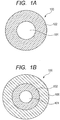
- Fig. 1A and Fig. 1B are cross sectional views of optical fibers according to embodiments of the present invention, which are each taken along a direction perpendicular to a longitudinal direction of the optical fiber.
- a glass core 101 is formed of a cylindrical quartz glass or the like, and may be added with a substance such as a rare-earth element depending on intended use.
- the diameter of the glass core 101 is changed as needed depending on the intended use, and may be 200 ⁇ m, or larger, for example.
- a polymer cladding 102 is formed using a polymerizable composition (A), a silane coupling agent (B), and a fluorine-based ultraviolet curable resin (C), and has a lower refractive index than the glass core 101 does.
- the thickness of the polymer cladding 102 is changed as needed depending on the intended use, and may be 25 ⁇ m, for example.
- the polymerizable composition (A) is a substance having good wettability on the surface of the glass core 101 and having good miscibility with the fluorine-based ultraviolet curable resin (C).
- the polymerizable composition (A) may be a polymerizable composition containing a fluorinated (meth)acrylate compound.
- the polymerizable composition (A) may be perfluorocyclohexylmethyl methacrylate, pentafluorobenzyl (meth)acrylate, pentafluorophenyl (meth)acrylate, perfluoronorbornylmethyl (meth)acrylate, 1H-perfluoroisobornyl (meth)acrylate, 2,2,3,3,4,4,5,5-octafluorohexanediol-1,6-diacrylate, perfluorocyclohexyl-1,4-dimethyldiacrylate, polyperfluoroethyleneglycol diacrylate, 2,2,3,3-tetrafluoro-1,4-butanediol diacrylate, hexafluoropentandiyl-1-5 bis(acrylate), hexafluorobisphenol A diacrylate, and the like.
- the silane coupling agent (B) is a substance dispersed in the polymerizable composition (A), and improving the adhesive force between the surface of the glass core 101 and the fluorine-based ultraviolet curable resin (C).
- the silane coupling agent (B) contains, as a reactive functional group, any of an acrylic group, a (meth)acrylic group, an epoxy group, a vinyl group, an amino group, a styryl group, a mercapto group, a ureido group, a sulfide group, an isocyanate group, and the like, and contains, as a hydrolyzable group, a methoxy group (OCH 3 ), an ethoxy group (OC 2 H 5 ), an acetoxy group (OCOCH 3 ), or the like.
- acrylic group is 3-acryloxypropyltrimethoxysilane.
- (meth)acrylic group include 3-methacryloxypropylmethyldimethoxysilane, 3-methacryloxypropyltrimethoxysilane, 3-methacryloxypropylmethyldiethoxysilane, and 3-methacryloxypropyltriethoxysilane.
- Examples of the epoxy group include 2-(3,4-epoxycyclohexyl)ethyltrimethoxysilane, 3-glycidoxypropylmethyldimethoxysilane, 3-glycidoxypropyltrimethoxysilane, 3-glycidoxypropylmethyldiethoxysilane, and 3-glycidoxypropyltriethoxysilane.
- Examples of the vinyl group include vinyltrimethoxysilane, and vinyltriethoxysilane.
- amino group examples include N-2-(aminoethyl)-3-aminopropylmethyldimethoxysilane, N-2-(aminoethyl)-3-aminopropyltrimethoxysilane, N-2-(aminoethyl)-3-aminopropyltriethoxysilane, 3-aminopropyltrimethoxysilane, 3-aminopropyltriethoxysilane, 3-triethoxysilyl-N-(1,3-dimethyl-butylidene) propylamine, N-phenyl-3-aminopropyltrimethoxysilane, and N-(vinylbenzyl)-2-aminoethyl-3-aminopropyltrimethoxysilane hydrochloride.
- styryl group is p-styryltrimethoxysilane.
- mercapto group include 3-mercaptopropylmethyldimethoxysilane, and 3-mercaptopropyltrimethoxysilane.
- ureido group is 3-ureidopropyltriethoxysilane.
- sulfide group is bis(triethoxysilylpropyl)tetrasulfide.
- isocyanate group is 3-isocyanatepropyltriethoxysilane.
- the fluorine-based ultraviolet curable resin (C) is an ultraviolet curable resin with a low refractive index, which has good miscibility with the polymerizable composition (A) and contains a relatively large amount of fluorine.
- the fluorine-based ultraviolet curable resin (C) alone i.e., the fluorine-based ultraviolet curable resin (C) not mixed with the polymerizable composition (A) and the silane coupling agent (B) desirably has a refractive index in a range of 1.350 to 1.420 after ultraviolet-curing.
- fluorine-based ultraviolet curable resin (C) is a mixture of components such as an acrylic-based oligomer, urethane acrylate having a perfluoropolyether group, a monofunctional fluorinated acrylate monomer, a bifunctional fluorinated acrylate monomer having a molecular weight of about 400 to 600, perfluoro polyether having two (meth)acrylate functional groups with a molecular weight of less than 1500, and a photopolymerization initiator (for example, Darocur 1173).
- a photopolymerization initiator for example, Darocur 1173
- a coating layer 106 to serve as a protective layer may be formed outside the polymer cladding 102.
- the coating layer 106 may contain a usual thermoplastic polymer or ultraviolet curable resin.
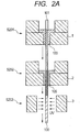
- Fig. 2A is a schematic view of apparatuses used in steps of manufacturing an optical fiber 100 according to an embodiment of the present invention.
- Fig. 2B is a schematic view illustrating cross sections of the optical fiber 100 in the manufacturing steps, the cross sections taken in parallel to a longitudinal direction of the optical fiber 100.
- Step S201 a drawn glass core 101 is supplied to a first coater apparatus 1.
- the first coater apparatus 1 is filled with a mixture 103 (also called “a primer") of a polymerizable composition (A) and a silane coupling agent (B) 104a which are mixed together at a predetermined ratio.
- the first coater apparatus applies the mixture 103 to the circumference of the glass core 101 with a predetermined thickness of T 0 while the mixture 103 is kept in a liquid state.
- the thickness T 0 is changed as needed depending on intended use, and may be preferably 20 ⁇ m or less, preferably 15 ⁇ m or less, and more preferably 10 ⁇ m or less.
- the silane coupling agent (B) 104a in the mixture 103 is dispersed in the polymerizable composition (A), and the polymerizable composition (A) has good wettability on the surface of the glass core 101. For these reasons, the silane coupling agent (B) 104a in the mixture 103 applied in step S201 evenly exists on the glass core 101.
- a second coater apparatus 2 is filled with a fluorine-based ultraviolet curable resin (C) 105 in a liquid state.
- the second coater apparatus 2 applies the fluorine-based ultraviolet curable resin (C) 105 onto the mixture 103 before the mixture 103 in the liquid state is dried.
- a liquid substance onto another liquid substance previously applied before the latter liquid substance is dried is referred to as "wet-on-wet” coating.
- the fluorine-based ultraviolet curable resin (C) 105 is applied by "wet-on-wet" coating onto the mixture 103.
- an ultraviolet irradiation apparatus 3 including a UV lamp or the like irradiates the fluorine-based ultraviolet curable resin (C) with ultraviolet rays, and thereby cures the fluorine-based ultraviolet curable resin (C).
- This process is referred to as an "ultraviolet curing process".
- the optical fiber 100 in which the polymer cladding 102 is formed around the glass core 101 is manufactured.
- the polymer cladding 102 often and generally has a low modulus of elasticity, and the coating layer 106 to serve as a protective layer may be formed outside the polymer cladding 102 if necessary.
- the protective layer be formed of an ultraviolet curable resin from the viewpoint of a manufacturing efficiency.
- the protective layer 106 may be formed of a material other than the ultraviolet curable resin such as an extruded coating of a thermoplastic polymer, or another coating layer may be additionally formed outside the protective layer 106 made of the ultraviolet curable resin.
- the protective layer 106 coated on the outside of the polymer cladding 102 and made of the ultraviolet curable resin may be formed by using, for example, a resin generally used as a secondary for usual optical fibers for communications.
- a component 104b originated from the silane coupling agent is locally concentrated within a predetermined range T in the polymer cladding 102 from an interface between the glass core 101 and the polymer cladding 102.
- the component 104b originated from the silane coupling agent is a substance in which the silane coupling agent (B) 104a and the fluorine-based ultraviolet curable resin (C) 105 are bonded together after reacting with each other.
- the predetermined range T is changed as needed depending on the intended use, and is 20 ⁇ m or less, preferably 15 ⁇ m or less, and more preferably 10 ⁇ m or less.
- the predetermined range T can be adjusted in step S201 by adjusting the thickness T 0 of the mixture 103 when applying the mixture 103 to the glass core 101, and in step S203 by subjecting the fluorine-based ultraviolet curable resin (C) 105 to the ultraviolet curing process before the silane coupling agent (B) contained in the mixture 103 is dispersed to the overall area of the fluorine-based ultraviolet curable resin (C) 105.
- the thickness T 0 of the mixture 103 applied to the glass core 101 is adjusted to approximately 10 ⁇ m or less in step S201, and the fluorine-based ultraviolet curable resin (C) 105 is subjected to the ultraviolet curing process within a predetermined time period in step S203 after the fluorine-based ultraviolet curable resin (C) 105 is applied.
- the component 104b originated from the silane coupling agent (B) can be concentrated within a range of 20 ⁇ m or less, preferably 15 ⁇ m or less, and more preferably 10 ⁇ m or less in the polymer cladding 102 from the interface between the glass core 101 and the polymer cladding 102.
- the predetermined time period mentioned above is determined depending on a substance used, and is obtained empirically.
- the use of the mixture 103 of the polymerizable composition (A) and the silane coupling agent (B) makes it possible to apply the silane coupling agent (B) evenly to the surface of the glass core 101.
- improvement in the coating properties of the mixture of the polymerizable composition (A) and the silane coupling agent (B) advantageously increases material choices for the fluorine-based ultraviolet curable resin (C).
- the component 104b originated from the silane coupling agent can be locally concentrated near the interface between the glass core 101 and the polymer cladding 102, i.e., within the predetermined range T in the polymer cladding 102 from the interface between the glass core 101 and the polymer cladding 102. This enables enhancement of an adhesive force between the glass core 101 and the polymer cladding 102, and reduction of an influence in which the refractive index of the polymer cladding 102 is increased by the component 104b originated from the silane coupling agent.
- Examples of the present invention are described.
- a ratio between the polymerizable composition (A) and the silane coupling agent (B) were varied variously while a ratio of the fluorine-based ultraviolet curable resin (C) was kept constant, and the following items were examined: an adhesive force between a glass core and a polymer cladding formed around the glass core; and a miscibility, coating properties, and a refractive index of a mixture of the polymerizable composition (A) and the silane coupling agent (B).
- Samples 1 to 8 each including a resin layer (equivalent to the polymer cladding) on a glass plate (equivalent to the glass core) were fabricated by: applying the mixture of the polymerizable composition (A) and the silane coupling agent (B) onto the glass plate by a spin coater or the like; and then applying the fluorine-based ultraviolet curable resin (C) by wet-on-wet coating onto the applied mixture by the spin coater or the like, followed by the ultraviolet curing process.
- fibers were manufactured by using the compositions and combinations of Samples 1 to 8.
- the fibers were each manufactured by forming a mixture layer + a polymer cladding layer around a silica core fiber having an outer diameter of 200 ⁇ m, so that the outer diameter of the resultant fiber was 300 ⁇ m.
- Transmission losses in each fiber at 850 nm when 24 to 36 hours elapsed after the manufacturing were measured by an OTDR. Thereafter, the transmission losses after 24-hour aging in a pressured thermostatic bath at 100°C and 100%RH were measured by the OTDR. Thus, increases in terms of the transmission loss before and after the aging were checked.
- Table 1 items "Initial loss (dB/km)" and “Loss after 24 hrs at 100°C and 100%RH (dB/km)" present the results.
- Table 1 presents the fabricated samples of Examples (Samples 1 to 5) and Comparative Examples (Samples 6 to 8). Note that, if the ratio of substances used is the same, a sample even in the form of a fiber can be expected to bring about the same results as in data of Table 1.
- the fluorine-based ultraviolet curable resin (C) was a glass plate made of quartz, perfluorocyclohexylmethyl methacrylate as the polymerizable composition (A), 3-acryloxypropyltrimethoxysilane as the silane coupling agent (B), and a mixture of a fluorine-rich acrylic oligomer, a photopolymerization initiator, and the like as the fluorine-based ultraviolet curable resin (C).
- the fluorine-based ultraviolet curable resin (C) alone had a refractive index of about 1.38 after ultraviolet curing.
- the unit for (A), (B) and (C) is “parts by weight", and the unit for the adhesive force is "N/mm 2 ".
- the adhesive force was obtained by: applying the mixture of (A) and (B) onto a washed glass plate by the spin coater or the like; further applying (C) by wet-on-wet coating thereon with a fixed thickness (for example, 100 ⁇ m); performing the ultraviolet curing process (irradiation conditions: 1500 mW, 1000 mJ) by a UV lamp; cutting the resultant plate into a piece with a certain width; and measuring a peel force at 90° of the cut piece by using a Tensilon universal testing machine or the like.
- the refractive index of the mixture of (A) and (B) was measured by using a sodium lamp with a wavelength of 589 nm as a light source, and using an Abbe refractometer at a temperature of 25°C.
- the miscibility of (A) and (B) were mixed in a glass container and then were allowed to stand for 24 hours. If the (A) and (B) were not separated into two layers, the miscibility was determined as " ⁇ ".
- the mixture of (A) and (B) was applied on a washed glass plate by the spin coater, and the coating properties were determined as " ⁇ " if the mixture was evenly applied, or determined as " ⁇ ” if the glass plate repelled the mixture and consequently remained partly uncoated.
- Sample 1 was fabricated by applying a mixture of 1.8 parts by weight of the polymerizable composition (A) and 0.2 parts by weight of the silane coupling agent (B) to a glass plate, and then applying 100 parts by weight of the fluorine-based ultraviolet curable resin (C) by wet-on-wet coating thereto, followed by the ultraviolet curing process.
- the refractive index of the mixture of the polymerizable composition (A) and the silane coupling agent (B) used to fabricate Sample 1 the refractive index was measured by using the sodium lamp with a wavelength of 589 nm as a light source, and using the Abbe refractometer at a temperature of 25°C. As a result, the refractive index was 1.373.
- the mixture was allowed to stand for 24 hours after the mixing. As a result, the polymerizable composition (A) and the silane coupling agent (B) in the mixture were not separated into two layers (" ⁇ ").
- the mixture was applied to the washed glass plate by the spin coater. As a result, the mixture was evenly applied to the glass plate (" ⁇ ").
- Fig. 3 is a plot diagram illustrating a relationship between the ratio "(B)/ ⁇ (A)+(B) ⁇ " of the silane coupling agent (B) to the mixture, and each of the refractive index and the adhesive force, presented in Table 1.
- Table 1 the ratio of the silane coupling agent (B) to the mixture of the polymerizable composition (A) and the silane coupling agent (B) increases, the refractive index increases, whereas the adhesive force increases and then decreases gently.
- the refractive index after ultraviolet curing of the fluorine-based ultraviolet curable resin (C) alone be within a range of 1.350 to 1.420.
- the refractive index of the mixture of the polymerizable composition (A) and the silane coupling agent (B) be within the same range and be low in order to reduce the influence on the refractive index of the fluorine-based ultraviolet curable resin (C).
- the ratio of the silane coupling agent to the mixture is desirably 10 to 80%, more desirably 10 to 50%, and even more desirably 20 to 40%.
Description
- The present invention relates to an optical fiber, and more specifically relates to a polymer clad optical fiber formed using a fluorine-based ultraviolet curable resin with a low refractive index and a method of manufacturing the same.
- In general, a polymer clad optical fiber has a structure in which a resin is formed around a core. The polymer clad optical fiber enables transmission of high density light energy and is used in fields which require transmission of high output light energy from a laser or the like, fields of sensors, and others. For manufacturing such optical fibers, it has been a conventional practice to mix an ultraviolet curable resin with a silane coupling agent to enhance adhesive properties between a glass core and the ultraviolet curable resin.
-
Patent Document 1 discloses an optical fiber manufacturing method which improves adhesive properties between a UV resin coating layer and a glass fiber.Patent Document 2 discloses that an adhesive force between an adhesive and a coated optical fiber is increased by thinly applying a silane coupling agent to the surface of a glass constituting the optical fiber.Patent Document 3 discloses an optical fiber manufacturing method which improves adhesive properties between a bare optical fiber and a coating layer. Patent Document 4 discloses an optical fiber having excellent fiber strength and transmission properties. - Patent Document 5 discloses a photocurable composition with a low refractive index, which has favorable viscosity and excellent mechanical properties such as toughness in a cured state, and which is easily synthesizable. Patent Document 6 discloses a double clad optical fiber which has favorable mechanical strength even with a single layer coating, and has a large numerical aperture.
- Patent document 7 discloses 1.1 in example 1 an optical fibre, comprising a quartz glass core with a diameter of 200 µm. The core is coated with a composition a which is a polymerisable precursor composition comprising various acrylates and 1 weight percent of the silane coupling agent. The outer diameter of the optical fibre including the first cladding is 216 µm. The thickness of the first cladding comprising the silane coupling agent is thus 8 µm, i.e less than 20 µm. On this first cladding a second layer made from a fluorine-based ultraviolet curable resin is applied. The refractive index of the fluoro-based ultraviolet curable resin is 1.409.
-
- Patent Document 1: Japanese Patent Application Laid-Open No.
H02-48434 - Patent Document 2: Japanese Patent Application Laid-Open No.
H05-224108 - Patent Document 3: Japanese Patent Application Laid-Open No.
2000-34137 - Patent Document 4: Japanese Patent Application Laid-Open No.
2011-33933 - Patent Document 5: Japanese Patent Application Laid-Open No.
H10-197731 - Patent Document 6: Japanese Patent Application Laid-Open No.
2012-18258 - Patent document 7:
US 6 222 972 B1 - In
Patent Document 1, a glass fiber is caused to pass through a vapor atmosphere of a silane coupling agent, whereby a silane coupling agent layer is formed on the surface of the glass fiber, and then an ultraviolet curable resin is coated thereon. InPatent Document 2, a portion of the coating of a multi-core optical fiber in its longitudinal direction is removed, and a silane coupling agent is applied by spray coating to a non-extended part of the exposed glass portion of the coated optical fiber. However, the methods ofPatent Documents - In
Patent Document 3, a bare optical fiber is coated with an ultraviolet curable resin with the outer circumference of the bare optical fiber supplied with moisture, which improves the effect of a silane coupling agent mixed in the ultraviolet curable resin. In the method ofPatent Document 3, however, a problem of a refractive index arises because the ultraviolet curable resin having a relatively-low refractive index is mixed with the silane coupling agent, and their poor miscibility also poses a problem of aggregation of the silane coupling agent, and a problem of phase separation of the silane coupling agent and the fluorine-based ultraviolet curable resin. - In Patent Document 4, an amount of a silane coupling agent contained in a curable composition containing a fluorine-based ultraviolet curable type resin is adjusted to ensure miscibility of the fluorine-based ultraviolet curable type resin and the silane coupling agent. However, in the method of Patent Document 4, it is difficult to apply the silane coupling agent evenly onto the surface of a core glass.
- The poor wettability of the silane coupling agent on the surface of a glass core entails a problem of a difficulty in applying the silane coupling agent evenly to the surface of a glass core. In addition, the mixing of the fluorine-based ultraviolet curable resin with the silane coupling agent causes a problem in that the refractive index of the fluorine-based ultraviolet curable resin is increased due to the influence of the silane coupling agent. Moreover, the miscibility of the fluorine-based ultraviolet curable resin with the low refractive index and the silane coupling agent is so poor that just simple mixing of them has a problem of aggregation of the silane coupling agent and a problem of phase separation of the silane coupling agent and the fluorine-based ultraviolet curable. Hence, in the manufacturing of polymer clad optical fibers, there has been a demand for solution to these problems.
- According to an embodiment of the present invention, provided is an optical fiber including a glass core and a polymer cladding consisting of a single layer and formed around the glass core, in which the polymer cladding includes a mixture of a polymerizable composition and a silane coupling agent, and a fluorine-based ultraviolet curable resin, the mixture contains 5 to 95 parts by weight of the silane coupling agent based on 100 parts by weight of a total weight of the mixture, the fluorine-based ultraviolet curable resin alone has a refractive index in a range of 1.350 to 1.420 after ultraviolet curing, and a component originated from the silane coupling agent is concentrated within a range of 20 µm or less in the polymer cladding from an interface between the glass core and the polymer cladding.
- In addition, according to an embodiment of the present invention, provided is a method of manufacturing an optical fiber, including the steps of: applying a mixture of a polymerizable composition and a silane coupling agent to a glass core; applying a fluorine-based ultraviolet curable resin onto the mixture; and forming a polymer cladding around the glass core by subjecting the fluorine-based ultraviolet curable resin to a ultraviolet curing process, in which the mixture contains 5 to 95 parts by weight of the silane coupling agent based on 100 parts by weight of a total weight of the mixture, the fluorine-based ultraviolet curable resin alone has a refractive index in a range of 1.350 to 1.420 after ultraviolet curing, and a component originated from the silane coupling agent is concentrated within a range of 20 µm or less in the polymer cladding from an interface between the glass core and the polymer cladding.
- According to an embodiment of the present invention, a silane coupling agent can be applied evenly to the surface of a glass core by using a mixture of the silane coupling agent and a polymerizable composition having good wettability on the surface of the glass core. In addition, according to an embodiment of the present invention, after a mixture of a polymerizable composition and a silane coupling agent is applied, a fluorine-based ultraviolet curable resin is applied by wet-on-wet coating onto the applied mixture. This makes it possible to avoid aggregation of the silane coupling agent or phase separation of the silane coupling agent and the fluorine-based ultraviolet curable resin. Further, in an embodiment of the present invention, a component originated from the silane coupling agent is concentrated within a range of 20 µm or less in the polymer cladding from the interface between the glass core and the polymer cladding, which enables reduction in an increase in the refractive index of the fluorine-based ultraviolet curable resin due to an influence of the silane coupling agent.
-
-
Fig. 1A is a cross sectional view of an optical fiber according to an embodiment of the present invention. -
Fig. 1B is a cross sectional view of an optical fiber according to an embodiment of the present invention. -
Fig. 2A is a schematic view of apparatuses used in steps of manufacturing an optical fiber according to an embodiment of the present invention. -
Fig. 2B is a schematic view illustrating cross sections of the optical fiber in the manufacturing steps according to the embodiment of the present invention, the cross sections taken in parallel to a longitudinal direction of the optical fiber. -
Fig. 3 is a plot diagram illustrating a relationship of a refractive index, an adhesive force, and so forth presented in Table 1. - Hereinafter, illustrative embodiments for implementing the present invention are described in details with reference to the drawings. It should be noted that the dimensions, materials, shapes, relative positions of constituent elements, and other things to be mentioned in the following embodiments are optional, and may be changed depending on the structures of apparatuses to which the present invention is applied, and depending on various conditions. In addition, unless otherwise specified, the scope of the present invention should not be limited to aspects described in detail in the following embodiments. Moreover, in the drawings described below, elements having the same function are denoted by the same reference numeral, and some part of the repetitive explanation thereof may be omitted.
-
Fig. 1A and Fig. 1B are cross sectional views of optical fibers according to embodiments of the present invention, which are each taken along a direction perpendicular to a longitudinal direction of the optical fiber. - A
glass core 101 is formed of a cylindrical quartz glass or the like, and may be added with a substance such as a rare-earth element depending on intended use. In addition, the diameter of theglass core 101 is changed as needed depending on the intended use, and may be 200 µm, or larger, for example. - A
polymer cladding 102 is formed using a polymerizable composition (A), a silane coupling agent (B), and a fluorine-based ultraviolet curable resin (C), and has a lower refractive index than theglass core 101 does. The thickness of thepolymer cladding 102 is changed as needed depending on the intended use, and may be 25 µm, for example. - The polymerizable composition (A) is a substance having good wettability on the surface of the
glass core 101 and having good miscibility with the fluorine-based ultraviolet curable resin (C). For example, the polymerizable composition (A) may be a polymerizable composition containing a fluorinated (meth)acrylate compound. Preferable examples of the fluorinated (meth)acrylate compound include 1H,1H-2,2,3,3,4,4,4-heptafluorobutyl acrylate available from Sigma-Aldrich, Saint Louis, Missouri; 1H,1H,2H,2H-perfluorodecyl acrylate and/or ω-hydro-2,2,3,3,4,4,5,5-octafluoropentyl acrylate both available from Lancaster Synthesis, Windham, New Hampshire; C9F9SO2N(CH3)CH2CH2OC(=O)CH=CH2 produced in the procedure of Examples 2A and 2B in Description ofUS patent No. 6,664,354 ; a fluorinated (meth)acrylic compound containing (perfluorocyclohexyl)methyl acrylate, which is described in Descriptions ofUS Patents No. 4,968,116 and No.5,239,026 ; and the like. Moreover, the polymerizable composition (A) may be perfluorocyclohexylmethyl methacrylate, pentafluorobenzyl (meth)acrylate, pentafluorophenyl (meth)acrylate, perfluoronorbornylmethyl (meth)acrylate, 1H-perfluoroisobornyl (meth)acrylate, 2,2,3,3,4,4,5,5-octafluorohexanediol-1,6-diacrylate, perfluorocyclohexyl-1,4-dimethyldiacrylate, polyperfluoroethyleneglycol diacrylate, 2,2,3,3-tetrafluoro-1,4-butanediol diacrylate, hexafluoropentandiyl-1-5 bis(acrylate), hexafluorobisphenol A diacrylate, and the like. - The silane coupling agent (B) is a substance dispersed in the polymerizable composition (A), and improving the adhesive force between the surface of the
glass core 101 and the fluorine-based ultraviolet curable resin (C). For example, the silane coupling agent (B) contains, as a reactive functional group, any of an acrylic group, a (meth)acrylic group, an epoxy group, a vinyl group, an amino group, a styryl group, a mercapto group, a ureido group, a sulfide group, an isocyanate group, and the like, and contains, as a hydrolyzable group, a methoxy group (OCH3), an ethoxy group (OC2H5), an acetoxy group (OCOCH3), or the like. An example of the acrylic group is 3-acryloxypropyltrimethoxysilane. Examples of the (meth)acrylic group include 3-methacryloxypropylmethyldimethoxysilane, 3-methacryloxypropyltrimethoxysilane, 3-methacryloxypropylmethyldiethoxysilane, and 3-methacryloxypropyltriethoxysilane. Examples of the epoxy group include 2-(3,4-epoxycyclohexyl)ethyltrimethoxysilane, 3-glycidoxypropylmethyldimethoxysilane, 3-glycidoxypropyltrimethoxysilane, 3-glycidoxypropylmethyldiethoxysilane, and 3-glycidoxypropyltriethoxysilane. Examples of the vinyl group include vinyltrimethoxysilane, and vinyltriethoxysilane. Examples of the amino group include N-2-(aminoethyl)-3-aminopropylmethyldimethoxysilane, N-2-(aminoethyl)-3-aminopropyltrimethoxysilane, N-2-(aminoethyl)-3-aminopropyltriethoxysilane, 3-aminopropyltrimethoxysilane, 3-aminopropyltriethoxysilane, 3-triethoxysilyl-N-(1,3-dimethyl-butylidene) propylamine, N-phenyl-3-aminopropyltrimethoxysilane, and N-(vinylbenzyl)-2-aminoethyl-3-aminopropyltrimethoxysilane hydrochloride. An example of the styryl group is p-styryltrimethoxysilane. Examples of the mercapto group include 3-mercaptopropylmethyldimethoxysilane, and 3-mercaptopropyltrimethoxysilane. An example of the ureido group is 3-ureidopropyltriethoxysilane. An example of the sulfide group is bis(triethoxysilylpropyl)tetrasulfide. An example of the isocyanate group is 3-isocyanatepropyltriethoxysilane. - The fluorine-based ultraviolet curable resin (C) is an ultraviolet curable resin with a low refractive index, which has good miscibility with the polymerizable composition (A) and contains a relatively large amount of fluorine. In the case of the polymer clad optical fiber generally used for a fiber laser and the like, the fluorine-based ultraviolet curable resin (C) alone, i.e., the fluorine-based ultraviolet curable resin (C) not mixed with the polymerizable composition (A) and the silane coupling agent (B) desirably has a refractive index in a range of 1.350 to 1.420 after ultraviolet-curing. An example of the fluorine-based ultraviolet curable resin (C) is a mixture of components such as an acrylic-based oligomer, urethane acrylate having a perfluoropolyether group, a monofunctional fluorinated acrylate monomer, a bifunctional fluorinated acrylate monomer having a molecular weight of about 400 to 600, perfluoro polyether having two (meth)acrylate functional groups with a molecular weight of less than 1500, and a photopolymerization initiator (for example, Darocur 1173).
- As illustrated in
Fig. 1B , acoating layer 106 to serve as a protective layer may be formed outside thepolymer cladding 102. Thecoating layer 106 may contain a usual thermoplastic polymer or ultraviolet curable resin. -
Fig. 2A is a schematic view of apparatuses used in steps of manufacturing anoptical fiber 100 according to an embodiment of the present invention.Fig. 2B is a schematic view illustrating cross sections of theoptical fiber 100 in the manufacturing steps, the cross sections taken in parallel to a longitudinal direction of theoptical fiber 100. - In Step S201, a drawn
glass core 101 is supplied to afirst coater apparatus 1. Thefirst coater apparatus 1 is filled with a mixture 103 (also called "a primer") of a polymerizable composition (A) and a silane coupling agent (B) 104a which are mixed together at a predetermined ratio. The first coater apparatus applies themixture 103 to the circumference of theglass core 101 with a predetermined thickness of T0 while themixture 103 is kept in a liquid state. The thickness T0 is changed as needed depending on intended use, and may be preferably 20 µm or less, preferably 15 µm or less, and more preferably 10 µm or less. - The silane coupling agent (B) 104a in the
mixture 103 is dispersed in the polymerizable composition (A), and the polymerizable composition (A) has good wettability on the surface of theglass core 101. For these reasons, the silane coupling agent (B) 104a in themixture 103 applied in step S201 evenly exists on theglass core 101. - A
second coater apparatus 2 is filled with a fluorine-based ultraviolet curable resin (C) 105 in a liquid state. In step S202, thesecond coater apparatus 2 applies the fluorine-based ultraviolet curable resin (C) 105 onto themixture 103 before themixture 103 in the liquid state is dried. Here, to further apply a liquid substance onto another liquid substance previously applied before the latter liquid substance is dried is referred to as "wet-on-wet" coating. In other words, in step S202, the fluorine-based ultraviolet curable resin (C) 105 is applied by "wet-on-wet" coating onto themixture 103. - Then, in step S203, an
ultraviolet irradiation apparatus 3 including a UV lamp or the like irradiates the fluorine-based ultraviolet curable resin (C) with ultraviolet rays, and thereby cures the fluorine-based ultraviolet curable resin (C). This process is referred to as an "ultraviolet curing process". In this way, theoptical fiber 100 in which thepolymer cladding 102 is formed around theglass core 101 is manufactured. - Note that, the
polymer cladding 102 often and generally has a low modulus of elasticity, and thecoating layer 106 to serve as a protective layer may be formed outside thepolymer cladding 102 if necessary. In this case, it is preferable that the protective layer be formed of an ultraviolet curable resin from the viewpoint of a manufacturing efficiency. Instead, theprotective layer 106 may be formed of a material other than the ultraviolet curable resin such as an extruded coating of a thermoplastic polymer, or another coating layer may be additionally formed outside theprotective layer 106 made of the ultraviolet curable resin. Theprotective layer 106 coated on the outside of thepolymer cladding 102 and made of the ultraviolet curable resin may be formed by using, for example, a resin generally used as a secondary for usual optical fibers for communications. - In the
optical fiber 100 according to the present embodiment, acomponent 104b originated from the silane coupling agent is locally concentrated within a predetermined range T in thepolymer cladding 102 from an interface between theglass core 101 and thepolymer cladding 102. Thecomponent 104b originated from the silane coupling agent is a substance in which the silane coupling agent (B) 104a and the fluorine-based ultraviolet curable resin (C) 105 are bonded together after reacting with each other. - The predetermined range T is changed as needed depending on the intended use, and is 20 µm or less, preferably 15 µm or less, and more preferably 10 µm or less. The predetermined range T can be adjusted in step S201 by adjusting the thickness T0 of the
mixture 103 when applying themixture 103 to theglass core 101, and in step S203 by subjecting the fluorine-based ultraviolet curable resin (C) 105 to the ultraviolet curing process before the silane coupling agent (B) contained in themixture 103 is dispersed to the overall area of the fluorine-based ultraviolet curable resin (C) 105. - For example, the thickness T0 of the
mixture 103 applied to theglass core 101 is adjusted to approximately 10 µm or less in step S201, and the fluorine-based ultraviolet curable resin (C) 105 is subjected to the ultraviolet curing process within a predetermined time period in step S203 after the fluorine-based ultraviolet curable resin (C) 105 is applied. Thereby, thecomponent 104b originated from the silane coupling agent (B) can be concentrated within a range of 20 µm or less, preferably 15 µm or less, and more preferably 10 µm or less in thepolymer cladding 102 from the interface between theglass core 101 and thepolymer cladding 102. Note that the predetermined time period mentioned above is determined depending on a substance used, and is obtained empirically. - According to the foregoing manufacturing method, the use of the
mixture 103 of the polymerizable composition (A) and the silane coupling agent (B) makes it possible to apply the silane coupling agent (B) evenly to the surface of theglass core 101. In addition, improvement in the coating properties of the mixture of the polymerizable composition (A) and the silane coupling agent (B) advantageously increases material choices for the fluorine-based ultraviolet curable resin (C). Moreover, thecomponent 104b originated from the silane coupling agent can be locally concentrated near the interface between theglass core 101 and thepolymer cladding 102, i.e., within the predetermined range T in thepolymer cladding 102 from the interface between theglass core 101 and thepolymer cladding 102. This enables enhancement of an adhesive force between theglass core 101 and thepolymer cladding 102, and reduction of an influence in which the refractive index of thepolymer cladding 102 is increased by thecomponent 104b originated from the silane coupling agent. - Hereinafter, Examples of the present invention are described. In Examples, a ratio between the polymerizable composition (A) and the silane coupling agent (B) were varied variously while a ratio of the fluorine-based ultraviolet curable resin (C) was kept constant, and the following items were examined: an adhesive force between a glass core and a polymer cladding formed around the glass core; and a miscibility, coating properties, and a refractive index of a mixture of the polymerizable composition (A) and the silane coupling agent (B).
- In Examples, a glass plate made of the same substance as the glass core (quartz in Examples presented herein) was used in order to make it easier to check the coating properties of the mixture and to measure the adhesive force of the mixture to the glass.
Samples 1 to 8 each including a resin layer (equivalent to the polymer cladding) on a glass plate (equivalent to the glass core) were fabricated by: applying the mixture of the polymerizable composition (A) and the silane coupling agent (B) onto the glass plate by a spin coater or the like; and then applying the fluorine-based ultraviolet curable resin (C) by wet-on-wet coating onto the applied mixture by the spin coater or the like, followed by the ultraviolet curing process. - Moreover, fibers were manufactured by using the compositions and combinations of
Samples 1 to 8. The fibers were each manufactured by forming a mixture layer + a polymer cladding layer around a silica core fiber having an outer diameter of 200 µm, so that the outer diameter of the resultant fiber was 300 µm. Transmission losses in each fiber at 850 nm when 24 to 36 hours elapsed after the manufacturing were measured by an OTDR. Thereafter, the transmission losses after 24-hour aging in a pressured thermostatic bath at 100°C and 100%RH were measured by the OTDR. Thus, increases in terms of the transmission loss before and after the aging were checked. In following Table 1, items "Initial loss (dB/km)" and "Loss after 24 hrs at 100°C and 100%RH (dB/km)" present the results. - Table 1 presents the fabricated samples of Examples (
Samples 1 to 5) and Comparative Examples (Samples 6 to 8). Note that, if the ratio of substances used is the same, a sample even in the form of a fiber can be expected to bring about the same results as in data of Table 1. - To obtain the data of Table 1, used were a glass plate made of quartz, perfluorocyclohexylmethyl methacrylate as the polymerizable composition (A), 3-acryloxypropyltrimethoxysilane as the silane coupling agent (B), and a mixture of a fluorine-rich acrylic oligomer, a photopolymerization initiator, and the like as the fluorine-based ultraviolet curable resin (C). The fluorine-based ultraviolet curable resin (C) alone had a refractive index of about 1.38 after ultraviolet curing.
[Table 1] Example Comparative Example Sample 1 Sample 2Sample 3Sample 4 Sample 5 Sample 6 Sample 7 Sample 8 Polymerizable composition (A) 1.8 1.5 1.2 1 0.5 2 0.2 0 Silane coupling agent (B) 0.2 0.5 0.8 1 1.5 0 1.8 2 Fluorine-based ultraviolet curable resin (C) 100 100 100 100 100 100 100 100 Adhesive force 20 42 41 47 50 6 40 38 (B)/{(A)+(B)} 10 25 40 50 75 0 90 100 Refractive index of mixture of (A) and (B) 1.373 1.382 1.392 1.397 1.418 1.37 1.425 1.427 Miscibility of (A) and (B) ○ ○ ○ ○ ○ - ○ - Coating properties of mixture of (A) and (B) ○ ○ ○ ○ ○ ○ × × Initial loss (dB/km) 4.2 3.8 4 3.6 3.5 4.5 6.5 6.2 Loss after 24 hrs at 100°C and 100%RH(dB/km) 3.8 4.5 4.1 4.2 3.9 10.2 7.7 5.8 - In Table 1, the unit for (A), (B) and (C) is "parts by weight", and the unit for the adhesive force is "N/mm2". The adhesive force was obtained by: applying the mixture of (A) and (B) onto a washed glass plate by the spin coater or the like; further applying (C) by wet-on-wet coating thereon with a fixed thickness (for example, 100 µm); performing the ultraviolet curing process (irradiation conditions: 1500 mW, 1000 mJ) by a UV lamp; cutting the resultant plate into a piece with a certain width; and measuring a peel force at 90° of the cut piece by using a Tensilon universal testing machine or the like.
- Then, the unit for (B)/{(A)+(B)} is "%". The refractive index of the mixture of (A) and (B) was measured by using a sodium lamp with a wavelength of 589 nm as a light source, and using an Abbe refractometer at a temperature of 25°C. As for the miscibility of (A) and (B), the (A) and (B) were mixed in a glass container and then were allowed to stand for 24 hours. If the (A) and (B) were not separated into two layers, the miscibility was determined as "○". As for the coating properties of the mixture of (A) and (B), the mixture of (A) and (B) was applied on a washed glass plate by the spin coater, and the coating properties were determined as "○" if the mixture was evenly applied, or determined as "×" if the glass plate repelled the mixture and consequently remained partly uncoated.
-
Sample 1 was fabricated by applying a mixture of 1.8 parts by weight of the polymerizable composition (A) and 0.2 parts by weight of the silane coupling agent (B) to a glass plate, and then applying 100 parts by weight of the fluorine-based ultraviolet curable resin (C) by wet-on-wet coating thereto, followed by the ultraviolet curing process. - In order to examine the adhesive force between the glass plate (equivalent to the glass core) and the resin layer (equivalent to the polymer cladding) in
Sample 1,Sample 1 was cut into a piece with a certain width, and a peel force at 90° was measured by using the Tensilon universal testing machine. As a result, the adhesive force was 20 N/mm2. - In order to examine the refractive index of the mixture of the polymerizable composition (A) and the silane coupling agent (B) used to fabricate
Sample 1, the refractive index was measured by using the sodium lamp with a wavelength of 589 nm as a light source, and using the Abbe refractometer at a temperature of 25°C. As a result, the refractive index was 1.373. In addition, in order to examine the miscibility of the mixture, the mixture was allowed to stand for 24 hours after the mixing. As a result, the polymerizable composition (A) and the silane coupling agent (B) in the mixture were not separated into two layers ("○"). Moreover, to examine the coating properties of the mixture, the mixture was applied to the washed glass plate by the spin coater. As a result, the mixture was evenly applied to the glass plate ("○"). - In the same manner as
Sample 1,Samples 2 to 8 were measured in the adhesive force and the others while the parts by weight of the polymerizable composition (A) and the parts by weight of the silane coupling agent (B) were variously changed as in the data of Table 1. -
Fig. 3 is a plot diagram illustrating a relationship between the ratio "(B)/{(A)+(B)}" of the silane coupling agent (B) to the mixture, and each of the refractive index and the adhesive force, presented in Table 1. As the ratio of the silane coupling agent (B) to the mixture of the polymerizable composition (A) and the silane coupling agent (B) increases, the refractive index increases, whereas the adhesive force increases and then decreases gently. - In addition, as a result of comparison between the transmission losses of the manufactured optical fiber before and after the aging, no increase in the losses before and after the aging was observed in Examples 1 to 5, whereas an increase in the loss after the aging was observed in Comparative Example 1. In addition, in Comparative Examples 2 and 3, even though a significant increase was not observed, the initial loss (before the aging) was unfavorably high due to an uneven formation of the mixture layer or the silane coupling agent layer.
- In the case of a polymer clad optical fiber for use for a fiber laser or the like, it is desirable that the refractive index after ultraviolet curing of the fluorine-based ultraviolet curable resin (C) alone be within a range of 1.350 to 1.420. For this reason, it is also desirable that the refractive index of the mixture of the polymerizable composition (A) and the silane coupling agent (B) be within the same range and be low in order to reduce the influence on the refractive index of the fluorine-based ultraviolet curable resin (C). Hence, in order to reduce the influence of the mixture containing the silane coupling agent (B) over the refractive index of the fluorine-based ultraviolet curable resin (C) while keeping the adhesive force, the ratio of the silane coupling agent to the mixture is desirably 10 to 80%, more desirably 10 to 50%, and even more desirably 20 to 40%.
-
- 100: optical fiber, 101: glass core, 102 polymer cladding, 103: mixture, 104a: silane coupling agent, 104b: component originated from silane coupling agent, 105: fluorine-based ultraviolet curable resin, 106: coating layer
Claims (3)
- An optical fiber comprising:a glass core; (101) anda polymer cladding (102) consisting of a single layer and formed around the glass core,whereinthe polymer cladding (102) comprises a mixture of a polymerizable composition and a silane coupling agent, and a fluorine-based ultraviolet curable resin,the mixture contains 5 to 95 parts by weight of the silane coupling agent based on 100 parts by weight of a total weight of the mixture,the fluorine-based ultraviolet curable resin alone has a refractive index in a range of 1.350 to 1.420 after ultraviolet curing, anda component originated from the silane coupling agent is concentrated within a range of 20 µm or less in the polymer cladding from an interface between the glass core and the polymer cladding.
- A method of manufacturing an optical fiber, (100) comprising the steps of:applying a mixture of a polymerizable composition and a silane coupling agent to a glass core; (101) applying a fluorine-based ultraviolet curable resin onto the mixture; andforming a polymer cladding (102) around the glass core by subjecting the fluorine-based ultraviolet curable resin to a ultraviolet curing process, whereinthe mixture contains 5 to 95 parts by weight of the silane coupling agent based on 100 parts by weight of a total weight of the mixture,the fluorine-based ultraviolet curable resin alone has a refractive index in a range of 1.350 to 1.420 after ultraviolet curing, anda component originated from the silane coupling agent is concentrated within a range of 20 µm or less in the polymer cladding (102) from an interface between the glass core (101) and the polymer cladding. (102)
- The method of manufacturing an optical fiber according to claim 2, wherein the mixture contains 10 to 50 parts by weight of the silane coupling agent.
Applications Claiming Priority (2)
| Application Number | Priority Date | Filing Date | Title |
|---|---|---|---|
| JP2013019537 | 2013-02-04 | ||
| PCT/JP2014/000293 WO2014119250A1 (en) | 2013-02-04 | 2014-01-22 | Optical fiber and method for producing same |
Publications (3)
| Publication Number | Publication Date |
|---|---|
| EP2952941A1 EP2952941A1 (en) | 2015-12-09 |
| EP2952941A4 EP2952941A4 (en) | 2016-08-31 |
| EP2952941B1 true EP2952941B1 (en) | 2018-01-03 |
Family
ID=51261967
Family Applications (1)
| Application Number | Title | Priority Date | Filing Date |
|---|---|---|---|
| EP14746476.2A Active EP2952941B1 (en) | 2013-02-04 | 2014-01-22 | Optical fiber and method for producing same |
Country Status (4)
| Country | Link |
|---|---|
| US (1) | US10793470B2 (en) |
| EP (1) | EP2952941B1 (en) |
| JP (2) | JPWO2014119250A1 (en) |
| WO (1) | WO2014119250A1 (en) |
Families Citing this family (2)
| Publication number | Priority date | Publication date | Assignee | Title |
|---|---|---|---|---|
| CN105837059B (en) * | 2016-04-22 | 2018-12-11 | 常州天马集团有限公司(原建材二五三厂) | Low grammes per square metre fiberglas chopped strand mat precursor and its manufacturing method |
| US11880061B2 (en) * | 2021-10-16 | 2024-01-23 | ZSquare Ltd. | Optical fiber from a single polymer |
Family Cites Families (20)
| Publication number | Priority date | Publication date | Assignee | Title |
|---|---|---|---|---|
| US4317616A (en) * | 1979-10-09 | 1982-03-02 | Raychem Corporation | Fluorosiloxane optical cladding |
| US4457970A (en) * | 1982-06-21 | 1984-07-03 | Ppg Industries, Inc. | Glass fiber reinforced thermoplastics |
| JPH0679095B2 (en) * | 1986-04-03 | 1994-10-05 | 旭硝子株式会社 | Plastic optical fiber transmission fiber |
| JPS63287908A (en) * | 1987-05-21 | 1988-11-25 | Asahi Glass Co Ltd | Optical fiber clad with plastic material |
| AU608420B2 (en) | 1988-03-15 | 1991-03-28 | Minnesota Mining And Manufacturing Company | Polymer claddings for optical fibre waveguides |
| JPH0248434A (en) * | 1988-08-05 | 1990-02-19 | Sumitomo Electric Ind Ltd | Production of optical fiber |
| JPH04198346A (en) * | 1990-11-28 | 1992-07-17 | Mitsubishi Rayon Co Ltd | Fluororesin composition |
| JPH05224108A (en) | 1991-06-28 | 1993-09-03 | Sumitomo Electric Ind Ltd | Method for reinforcing multiple optical fiber coupler |
| US5239026A (en) | 1991-08-26 | 1993-08-24 | Minnesota Mining And Manufacturing Company | Low loss high numerical aperture cladded optical fibers |
| JPH0961643A (en) * | 1995-08-23 | 1997-03-07 | Toray Ind Inc | Wide band plastic clad optical fiber and optical fiber cord with connector |
| JPH09222526A (en) * | 1995-12-12 | 1997-08-26 | Toray Ind Inc | Wide-band plastic clad optical fiber |
| JPH10160947A (en) * | 1996-11-29 | 1998-06-19 | Toray Ind Inc | Wide-band plastic clad optical fiber |
| US5822489A (en) | 1996-12-31 | 1998-10-13 | Lucent Technologies, Inc. | Low refractive index photo-curable composition for waveguide applications |
| US6246824B1 (en) * | 1997-03-18 | 2001-06-12 | Dsm N.V. | Method for curing optical glass fiber coatings and inks by low power electron beam radiation |
| JP4094128B2 (en) | 1998-07-17 | 2008-06-04 | 株式会社フジクラ | Manufacturing method and manufacturing apparatus for optical fiber |
| JP2000214342A (en) | 1999-01-21 | 2000-08-04 | Sumitomo Electric Ind Ltd | Plastic clad optical fiber and its production |
| DE60042561D1 (en) | 1999-10-27 | 2009-08-27 | 3M Innovative Properties Co | FLUOROCHEMICAL SULPHONAMIDE TENSIDES |
| JP2011033933A (en) | 2009-08-04 | 2011-02-17 | Sumitomo Electric Ind Ltd | Plastic clad optical fiber and method for manufacturing the same |
| JP2012018258A (en) | 2010-07-07 | 2012-01-26 | Furukawa Electric Co Ltd:The | Optical fiber core wire |
| JP2012042795A (en) * | 2010-08-20 | 2012-03-01 | Sumitomo Electric Ind Ltd | Hard plastic clad primary coated optical fiber |
-
2014
- 2014-01-22 EP EP14746476.2A patent/EP2952941B1/en active Active
- 2014-01-22 JP JP2014559551A patent/JPWO2014119250A1/en active Pending
- 2014-01-22 WO PCT/JP2014/000293 patent/WO2014119250A1/en active Application Filing
-
2015
- 2015-07-15 US US14/800,160 patent/US10793470B2/en active Active
-
2019
- 2019-04-25 JP JP2019083851A patent/JP6858216B2/en active Active
Non-Patent Citations (1)
| Title |
|---|
| None * |
Also Published As
| Publication number | Publication date |
|---|---|
| JPWO2014119250A1 (en) | 2017-01-26 |
| JP2019164360A (en) | 2019-09-26 |
| US10793470B2 (en) | 2020-10-06 |
| EP2952941A1 (en) | 2015-12-09 |
| WO2014119250A1 (en) | 2014-08-07 |
| US20150315072A1 (en) | 2015-11-05 |
| EP2952941A4 (en) | 2016-08-31 |
| JP6858216B2 (en) | 2021-04-14 |
Similar Documents
| Publication | Publication Date | Title |
|---|---|---|
| KR20180102061A (en) | BENDING-INSENSITIVE, RADIATION-RESISTANT SINGLE-MODE OPTICAL FIBER | |
| JPH01133011A (en) | Optical fiber with synthetic resin coating and manufacture thereof | |
| CN108802898A (en) | A kind of large mode field mixes ytterbium Active Optical Fiber and preparation method thereof | |
| US10816732B2 (en) | Low dn/dT optical adhesives | |
| JP5049574B2 (en) | Optical film, polarizing plate, image display device, and optical film manufacturing method | |
| JPH10160947A (en) | Wide-band plastic clad optical fiber | |
| EP2730955A1 (en) | Haze-proof optical article and method for producing same | |
| WO2008012926A1 (en) | Optical fiber | |
| JP6858216B2 (en) | Optical fiber and its manufacturing method | |
| BRPI0722193A2 (en) | PROCESS FOR MANUFACTING AN OPTICAL FIBER, OPTICAL FIBER, OPTICAL FIBER TAPE, AND APPLIANCE FOR PRODUCING AN OPTICAL FIBER | |
| JP2007168429A (en) | Antireflection film, its manufacturing method and polarizing plate using the same, and display device | |
| Murata et al. | UV-curable adhesives for optical communications | |
| JP4589211B2 (en) | UV curable liquid resin composition for optics | |
| US7939576B2 (en) | Antireflection film, process of producing the same, and polarizing plate and display device including the same | |
| EP0260756B1 (en) | Method of manufacturing an optical fibre | |
| EP2253978A1 (en) | Optical fiber core | |
| JP2009198706A (en) | Polymer clad coated optical fiber | |
| JP4952140B2 (en) | Polymer clad optical fiber | |
| EP0024593B1 (en) | Process for making an optical waveguide with high tensile strength | |
| US11130703B2 (en) | Method of manufacturing a bendable substrate coated with a coating layer of adjacent heterogeneous coatings bonded along boundaries thereof useful for foldable displays | |
| EP1022592A1 (en) | Plastic clad optical fiber and manufacturing method therof | |
| CN208805590U (en) | A kind of large mode field mixes ytterbium Active Optical Fiber | |
| JP3518089B2 (en) | Broadband optical fiber, its core, cord, and optical fiber with connector, cord | |
| JP2007256925A (en) | Optical film, antireflection film, polarizing plate, display apparatus and method for manufacturing optical film | |
| JP3084702B2 (en) | Glass fiber for optical transmission |
Legal Events
| Date | Code | Title | Description |
|---|---|---|---|
| PUAI | Public reference made under article 153(3) epc to a published international application that has entered the european phase |
Free format text: ORIGINAL CODE: 0009012 |
|
| 17P | Request for examination filed |
Effective date: 20150709 |
|
| AK | Designated contracting states |
Kind code of ref document: A1 Designated state(s): AL AT BE BG CH CY CZ DE DK EE ES FI FR GB GR HR HU IE IS IT LI LT LU LV MC MK MT NL NO PL PT RO RS SE SI SK SM TR |
|
| AX | Request for extension of the european patent |
Extension state: BA ME |
|
| DAX | Request for extension of the european patent (deleted) | ||
| A4 | Supplementary search report drawn up and despatched |
Effective date: 20160801 |
|
| RIC1 | Information provided on ipc code assigned before grant |
Ipc: G02B 6/00 20060101AFI20160726BHEP |
|
| GRAP | Despatch of communication of intention to grant a patent |
Free format text: ORIGINAL CODE: EPIDOSNIGR1 |
|
| STAA | Information on the status of an ep patent application or granted ep patent |
Free format text: STATUS: GRANT OF PATENT IS INTENDED |
|
| INTG | Intention to grant announced |
Effective date: 20170821 |
|
| GRAS | Grant fee paid |
Free format text: ORIGINAL CODE: EPIDOSNIGR3 |
|
| GRAA | (expected) grant |
Free format text: ORIGINAL CODE: 0009210 |
|
| STAA | Information on the status of an ep patent application or granted ep patent |
Free format text: STATUS: THE PATENT HAS BEEN GRANTED |
|
| AK | Designated contracting states |
Kind code of ref document: B1 Designated state(s): AL AT BE BG CH CY CZ DE DK EE ES FI FR GB GR HR HU IE IS IT LI LT LU LV MC MK MT NL NO PL PT RO RS SE SI SK SM TR |
|
| REG | Reference to a national code |
Ref country code: GB Ref legal event code: FG4D |
|
| REG | Reference to a national code |
Ref country code: CH Ref legal event code: EP Ref country code: AT Ref legal event code: REF Ref document number: 960813 Country of ref document: AT Kind code of ref document: T Effective date: 20180115 |
|
| REG | Reference to a national code |
Ref country code: FR Ref legal event code: PLFP Year of fee payment: 5 |
|
| REG | Reference to a national code |
Ref country code: IE Ref legal event code: FG4D |
|
| REG | Reference to a national code |
Ref country code: DE Ref legal event code: R096 Ref document number: 602014019424 Country of ref document: DE |
|
| REG | Reference to a national code |
Ref country code: NL Ref legal event code: MP Effective date: 20180103 |
|
| REG | Reference to a national code |
Ref country code: LT Ref legal event code: MG4D |
|
| REG | Reference to a national code |
Ref country code: AT Ref legal event code: MK05 Ref document number: 960813 Country of ref document: AT Kind code of ref document: T Effective date: 20180103 |
|
| PG25 | Lapsed in a contracting state [announced via postgrant information from national office to epo] |
Ref country code: NL Free format text: LAPSE BECAUSE OF FAILURE TO SUBMIT A TRANSLATION OF THE DESCRIPTION OR TO PAY THE FEE WITHIN THE PRESCRIBED TIME-LIMIT Effective date: 20180103 |
|
| PG25 | Lapsed in a contracting state [announced via postgrant information from national office to epo] |
Ref country code: FI Free format text: LAPSE BECAUSE OF FAILURE TO SUBMIT A TRANSLATION OF THE DESCRIPTION OR TO PAY THE FEE WITHIN THE PRESCRIBED TIME-LIMIT Effective date: 20180103 Ref country code: CY Free format text: LAPSE BECAUSE OF FAILURE TO SUBMIT A TRANSLATION OF THE DESCRIPTION OR TO PAY THE FEE WITHIN THE PRESCRIBED TIME-LIMIT Effective date: 20180103 Ref country code: LT Free format text: LAPSE BECAUSE OF FAILURE TO SUBMIT A TRANSLATION OF THE DESCRIPTION OR TO PAY THE FEE WITHIN THE PRESCRIBED TIME-LIMIT Effective date: 20180103 Ref country code: ES Free format text: LAPSE BECAUSE OF FAILURE TO SUBMIT A TRANSLATION OF THE DESCRIPTION OR TO PAY THE FEE WITHIN THE PRESCRIBED TIME-LIMIT Effective date: 20180103 Ref country code: NO Free format text: LAPSE BECAUSE OF FAILURE TO SUBMIT A TRANSLATION OF THE DESCRIPTION OR TO PAY THE FEE WITHIN THE PRESCRIBED TIME-LIMIT Effective date: 20180403 Ref country code: HR Free format text: LAPSE BECAUSE OF FAILURE TO SUBMIT A TRANSLATION OF THE DESCRIPTION OR TO PAY THE FEE WITHIN THE PRESCRIBED TIME-LIMIT Effective date: 20180103 |
|
| PG25 | Lapsed in a contracting state [announced via postgrant information from national office to epo] |
Ref country code: IS Free format text: LAPSE BECAUSE OF FAILURE TO SUBMIT A TRANSLATION OF THE DESCRIPTION OR TO PAY THE FEE WITHIN THE PRESCRIBED TIME-LIMIT Effective date: 20180503 Ref country code: BG Free format text: LAPSE BECAUSE OF FAILURE TO SUBMIT A TRANSLATION OF THE DESCRIPTION OR TO PAY THE FEE WITHIN THE PRESCRIBED TIME-LIMIT Effective date: 20180403 Ref country code: AT Free format text: LAPSE BECAUSE OF FAILURE TO SUBMIT A TRANSLATION OF THE DESCRIPTION OR TO PAY THE FEE WITHIN THE PRESCRIBED TIME-LIMIT Effective date: 20180103 Ref country code: SE Free format text: LAPSE BECAUSE OF FAILURE TO SUBMIT A TRANSLATION OF THE DESCRIPTION OR TO PAY THE FEE WITHIN THE PRESCRIBED TIME-LIMIT Effective date: 20180103 Ref country code: LV Free format text: LAPSE BECAUSE OF FAILURE TO SUBMIT A TRANSLATION OF THE DESCRIPTION OR TO PAY THE FEE WITHIN THE PRESCRIBED TIME-LIMIT Effective date: 20180103 Ref country code: RS Free format text: LAPSE BECAUSE OF FAILURE TO SUBMIT A TRANSLATION OF THE DESCRIPTION OR TO PAY THE FEE WITHIN THE PRESCRIBED TIME-LIMIT Effective date: 20180103 Ref country code: PL Free format text: LAPSE BECAUSE OF FAILURE TO SUBMIT A TRANSLATION OF THE DESCRIPTION OR TO PAY THE FEE WITHIN THE PRESCRIBED TIME-LIMIT Effective date: 20180103 Ref country code: GR Free format text: LAPSE BECAUSE OF FAILURE TO SUBMIT A TRANSLATION OF THE DESCRIPTION OR TO PAY THE FEE WITHIN THE PRESCRIBED TIME-LIMIT Effective date: 20180404 |
|
| REG | Reference to a national code |
Ref country code: CH Ref legal event code: PL |
|
| REG | Reference to a national code |
Ref country code: DE Ref legal event code: R097 Ref document number: 602014019424 Country of ref document: DE |
|
| PG25 | Lapsed in a contracting state [announced via postgrant information from national office to epo] |
Ref country code: LU Free format text: LAPSE BECAUSE OF NON-PAYMENT OF DUE FEES Effective date: 20180122 Ref country code: EE Free format text: LAPSE BECAUSE OF FAILURE TO SUBMIT A TRANSLATION OF THE DESCRIPTION OR TO PAY THE FEE WITHIN THE PRESCRIBED TIME-LIMIT Effective date: 20180103 Ref country code: RO Free format text: LAPSE BECAUSE OF FAILURE TO SUBMIT A TRANSLATION OF THE DESCRIPTION OR TO PAY THE FEE WITHIN THE PRESCRIBED TIME-LIMIT Effective date: 20180103 Ref country code: AL Free format text: LAPSE BECAUSE OF FAILURE TO SUBMIT A TRANSLATION OF THE DESCRIPTION OR TO PAY THE FEE WITHIN THE PRESCRIBED TIME-LIMIT Effective date: 20180103 Ref country code: MC Free format text: LAPSE BECAUSE OF FAILURE TO SUBMIT A TRANSLATION OF THE DESCRIPTION OR TO PAY THE FEE WITHIN THE PRESCRIBED TIME-LIMIT Effective date: 20180103 |
|
| REG | Reference to a national code |
Ref country code: IE Ref legal event code: MM4A |
|
| REG | Reference to a national code |
Ref country code: BE Ref legal event code: MM Effective date: 20180131 |
|
| PLBE | No opposition filed within time limit |
Free format text: ORIGINAL CODE: 0009261 |
|
| STAA | Information on the status of an ep patent application or granted ep patent |
Free format text: STATUS: NO OPPOSITION FILED WITHIN TIME LIMIT |
|
| PG25 | Lapsed in a contracting state [announced via postgrant information from national office to epo] |
Ref country code: LI Free format text: LAPSE BECAUSE OF NON-PAYMENT OF DUE FEES Effective date: 20180131 Ref country code: DK Free format text: LAPSE BECAUSE OF FAILURE TO SUBMIT A TRANSLATION OF THE DESCRIPTION OR TO PAY THE FEE WITHIN THE PRESCRIBED TIME-LIMIT Effective date: 20180103 Ref country code: CH Free format text: LAPSE BECAUSE OF NON-PAYMENT OF DUE FEES Effective date: 20180131 Ref country code: BE Free format text: LAPSE BECAUSE OF NON-PAYMENT OF DUE FEES Effective date: 20180131 Ref country code: SK Free format text: LAPSE BECAUSE OF FAILURE TO SUBMIT A TRANSLATION OF THE DESCRIPTION OR TO PAY THE FEE WITHIN THE PRESCRIBED TIME-LIMIT Effective date: 20180103 Ref country code: SM Free format text: LAPSE BECAUSE OF FAILURE TO SUBMIT A TRANSLATION OF THE DESCRIPTION OR TO PAY THE FEE WITHIN THE PRESCRIBED TIME-LIMIT Effective date: 20180103 Ref country code: CZ Free format text: LAPSE BECAUSE OF FAILURE TO SUBMIT A TRANSLATION OF THE DESCRIPTION OR TO PAY THE FEE WITHIN THE PRESCRIBED TIME-LIMIT Effective date: 20180103 |
|
| 26N | No opposition filed |
Effective date: 20181005 |
|
| GBPC | Gb: european patent ceased through non-payment of renewal fee |
Effective date: 20180403 |
|
| PG25 | Lapsed in a contracting state [announced via postgrant information from national office to epo] |
Ref country code: IE Free format text: LAPSE BECAUSE OF NON-PAYMENT OF DUE FEES Effective date: 20180122 |
|
| PG25 | Lapsed in a contracting state [announced via postgrant information from national office to epo] |
Ref country code: SI Free format text: LAPSE BECAUSE OF FAILURE TO SUBMIT A TRANSLATION OF THE DESCRIPTION OR TO PAY THE FEE WITHIN THE PRESCRIBED TIME-LIMIT Effective date: 20180103 Ref country code: GB Free format text: LAPSE BECAUSE OF NON-PAYMENT OF DUE FEES Effective date: 20180403 |
|
| PG25 | Lapsed in a contracting state [announced via postgrant information from national office to epo] |
Ref country code: MT Free format text: LAPSE BECAUSE OF NON-PAYMENT OF DUE FEES Effective date: 20180122 |
|
| PG25 | Lapsed in a contracting state [announced via postgrant information from national office to epo] |
Ref country code: TR Free format text: LAPSE BECAUSE OF FAILURE TO SUBMIT A TRANSLATION OF THE DESCRIPTION OR TO PAY THE FEE WITHIN THE PRESCRIBED TIME-LIMIT Effective date: 20180103 |
|
| PG25 | Lapsed in a contracting state [announced via postgrant information from national office to epo] |
Ref country code: PT Free format text: LAPSE BECAUSE OF FAILURE TO SUBMIT A TRANSLATION OF THE DESCRIPTION OR TO PAY THE FEE WITHIN THE PRESCRIBED TIME-LIMIT Effective date: 20180103 |
|
| PG25 | Lapsed in a contracting state [announced via postgrant information from national office to epo] |
Ref country code: HU Free format text: LAPSE BECAUSE OF FAILURE TO SUBMIT A TRANSLATION OF THE DESCRIPTION OR TO PAY THE FEE WITHIN THE PRESCRIBED TIME-LIMIT; INVALID AB INITIO Effective date: 20140122 Ref country code: MK Free format text: LAPSE BECAUSE OF NON-PAYMENT OF DUE FEES Effective date: 20180103 |
|
| PGFP | Annual fee paid to national office [announced via postgrant information from national office to epo] |
Ref country code: IT Payment date: 20221213 Year of fee payment: 10 Ref country code: DE Payment date: 20221130 Year of fee payment: 10 |
|
| P01 | Opt-out of the competence of the unified patent court (upc) registered |
Effective date: 20230512 |
|
| PGFP | Annual fee paid to national office [announced via postgrant information from national office to epo] |
Ref country code: FR Payment date: 20231212 Year of fee payment: 11 |