EP2952932B1 - Positron ct apparatus - Google Patents
Positron ct apparatus Download PDFInfo
- Publication number
- EP2952932B1 EP2952932B1 EP14746255.0A EP14746255A EP2952932B1 EP 2952932 B1 EP2952932 B1 EP 2952932B1 EP 14746255 A EP14746255 A EP 14746255A EP 2952932 B1 EP2952932 B1 EP 2952932B1
- Authority
- EP
- European Patent Office
- Prior art keywords
- detector units
- holding
- detector
- positron
- holding arms
- Prior art date
- Legal status (The legal status is an assumption and is not a legal conclusion. Google has not performed a legal analysis and makes no representation as to the accuracy of the status listed.)
- Not-in-force
Links
Images


Classifications
-
- A—HUMAN NECESSITIES
- A61—MEDICAL OR VETERINARY SCIENCE; HYGIENE
- A61B—DIAGNOSIS; SURGERY; IDENTIFICATION
- A61B6/00—Apparatus for radiation diagnosis, e.g. combined with radiation therapy equipment
- A61B6/02—Devices for diagnosis sequentially in different planes; Stereoscopic radiation diagnosis
- A61B6/03—Computerised tomographs
- A61B6/037—Emission tomography
-
- A—HUMAN NECESSITIES
- A61—MEDICAL OR VETERINARY SCIENCE; HYGIENE
- A61B—DIAGNOSIS; SURGERY; IDENTIFICATION
- A61B6/00—Apparatus for radiation diagnosis, e.g. combined with radiation therapy equipment
- A61B6/04—Positioning of patients; Tiltable beds or the like
- A61B6/0407—Supports, e.g. tables or beds, for the body or parts of the body
-
- A—HUMAN NECESSITIES
- A61—MEDICAL OR VETERINARY SCIENCE; HYGIENE
- A61B—DIAGNOSIS; SURGERY; IDENTIFICATION
- A61B6/00—Apparatus for radiation diagnosis, e.g. combined with radiation therapy equipment
- A61B6/10—Application or adaptation of safety means
- A61B6/102—Protection against mechanical damage, e.g. anti-collision devices
-
- A—HUMAN NECESSITIES
- A61—MEDICAL OR VETERINARY SCIENCE; HYGIENE
- A61B—DIAGNOSIS; SURGERY; IDENTIFICATION
- A61B6/00—Apparatus for radiation diagnosis, e.g. combined with radiation therapy equipment
- A61B6/40—Apparatus for radiation diagnosis, e.g. combined with radiation therapy equipment with arrangements for generating radiation specially adapted for radiation diagnosis
- A61B6/4057—Apparatus for radiation diagnosis, e.g. combined with radiation therapy equipment with arrangements for generating radiation specially adapted for radiation diagnosis by using radiation sources located in the interior of the body
-
- A—HUMAN NECESSITIES
- A61—MEDICAL OR VETERINARY SCIENCE; HYGIENE
- A61B—DIAGNOSIS; SURGERY; IDENTIFICATION
- A61B6/00—Apparatus for radiation diagnosis, e.g. combined with radiation therapy equipment
- A61B6/42—Apparatus for radiation diagnosis, e.g. combined with radiation therapy equipment with arrangements for detecting radiation specially adapted for radiation diagnosis
- A61B6/4266—Apparatus for radiation diagnosis, e.g. combined with radiation therapy equipment with arrangements for detecting radiation specially adapted for radiation diagnosis characterised by using a plurality of detector units
-
- A—HUMAN NECESSITIES
- A61—MEDICAL OR VETERINARY SCIENCE; HYGIENE
- A61B—DIAGNOSIS; SURGERY; IDENTIFICATION
- A61B6/00—Apparatus for radiation diagnosis, e.g. combined with radiation therapy equipment
- A61B6/42—Apparatus for radiation diagnosis, e.g. combined with radiation therapy equipment with arrangements for detecting radiation specially adapted for radiation diagnosis
- A61B6/4275—Apparatus for radiation diagnosis, e.g. combined with radiation therapy equipment with arrangements for detecting radiation specially adapted for radiation diagnosis using a detector unit almost surrounding the patient, e.g. more than 180°
-
- A—HUMAN NECESSITIES
- A61—MEDICAL OR VETERINARY SCIENCE; HYGIENE
- A61B—DIAGNOSIS; SURGERY; IDENTIFICATION
- A61B6/00—Apparatus for radiation diagnosis, e.g. combined with radiation therapy equipment
- A61B6/44—Constructional features of apparatus for radiation diagnosis
- A61B6/4405—Constructional features of apparatus for radiation diagnosis the apparatus being movable or portable, e.g. handheld or mounted on a trolley
-
- A—HUMAN NECESSITIES
- A61—MEDICAL OR VETERINARY SCIENCE; HYGIENE
- A61B—DIAGNOSIS; SURGERY; IDENTIFICATION
- A61B6/00—Apparatus for radiation diagnosis, e.g. combined with radiation therapy equipment
- A61B6/44—Constructional features of apparatus for radiation diagnosis
- A61B6/4429—Constructional features of apparatus for radiation diagnosis related to the mounting of source units and detector units
- A61B6/4435—Constructional features of apparatus for radiation diagnosis related to the mounting of source units and detector units the source unit and the detector unit being coupled by a rigid structure
- A61B6/4441—Constructional features of apparatus for radiation diagnosis related to the mounting of source units and detector units the source unit and the detector unit being coupled by a rigid structure the rigid structure being a C-arm or U-arm
-
- A—HUMAN NECESSITIES
- A61—MEDICAL OR VETERINARY SCIENCE; HYGIENE
- A61B—DIAGNOSIS; SURGERY; IDENTIFICATION
- A61B6/00—Apparatus for radiation diagnosis, e.g. combined with radiation therapy equipment
- A61B6/52—Devices using data or image processing specially adapted for radiation diagnosis
- A61B6/5205—Devices using data or image processing specially adapted for radiation diagnosis involving processing of raw data to produce diagnostic data
-
- G—PHYSICS
- G01—MEASURING; TESTING
- G01T—MEASUREMENT OF NUCLEAR OR X-RADIATION
- G01T1/00—Measuring X-radiation, gamma radiation, corpuscular radiation, or cosmic radiation
- G01T1/29—Measurement performed on radiation beams, e.g. position or section of the beam; Measurement of spatial distribution of radiation
- G01T1/2914—Measurement of spatial distribution of radiation
- G01T1/2985—In depth localisation, e.g. using positron emitters; Tomographic imaging (longitudinal and transverse section imaging; apparatus for radiation diagnosis sequentially in different planes, steroscopic radiation diagnosis)
Definitions
- the present invention relates to a positron CT apparatus that detects radiation emitted from positron radiopharmaceutical administered to a subject and generates a distribution image of positrons as an image. More particularly, the present invention is directed to a technique of imaging a human body for a subject.
- a positron CT apparatus i.e., a PET (Positron Emission Tomography) apparatus reconstructs a tomographic image of a subject only upon simultaneous detection (i.e., coincidence counting) of two gamma-rays generated through annihilation of a positive electron (Positron) with a plurality of detectors.
- the radiopharmaceutical containing positron-emitting radionuclide is administered to the subject.
- pair annihilation gamma-rays of 511Kev emitted from the administered subject are detected with detectors each formed by groups of many detector elements (e.g., scintillators).
- a line (LOR: Line Of Response) is identified that connects the two detectors that detect positions where the pair annihilation gamma-rays are generated. Then information on coincidence that is detected in such a manner is stored for reconstruction, whereby a positron-emitting radionuclide image (i.e., a tomographic image) is obtained.
- the present Applicant has suggested another type of PET apparatus. See Japanese Patent No. 4650324 . That is, the PET apparatus is configured such that detector units and holding arms holding the detector units are mounted on a transportable carriage, and the detector units are disposed so as to surround the bed.
- the bed of the existing modality apparatus e.g., X-ray CT apparatus
- the carriage is transported close to the modality apparatus.
- This allows arrangement of the detector units adjacent to the modality apparatus. Consequently, additional arrangement of the PET apparatus to the existing modality apparatus is performable without new purchase of a plurality of PET apparatus and modality apparatus.
- the PET apparatus includes two holding arms A 1 , A 2 (a first C-shape arm, and a second C-shape arm) in an arc shape.
- the holding arms include at tips thereof detector units U 1 , U 2 (a first gamma-ray detector, and second gamma-ray detector), respectively.
- the two holding arms A 1 , A 2 move independently along a circle surrounding the subject M, thereby changing inclination angles of the detector units U 1 , U 2 such that surfaces of the detector units U 1 , U 2 into which gamma-rays enter face to each other across the subject M.
- Such a configuration allows variation in distance between the detector units U 1 , U 2 depending on a size of the subject M while the inclination angles are changed as illustrated in Figures 11(a) and 11(b) . This achieves radiography while the detector units U 1 , U 2 face to each other.
- JP 2007 263865 A discloses a nuclear medicine diagnosis device, including a first C-shaped arm member, on which a first gamma-ray detector is mounted by an arm member moving mechanism, and a second C-shaped arm member, on which a second gamma-ray detector is mounted, which are moved in the direction wherein both arm members are brought close, thereby bringing both the first and second gamma-ray detectors close to the specimen.
- Each tilt angle of both the first and second gamma-ray detectors is changed by a detector angle adjusting mechanism, to acquire each gamma-ray detection attitude.
- the RI distribution image is radiographed in a state where the first and second gamma-ray detectors are both brought sufficiently close to the specimen M beforehand.
- JP H11 285492 A discloses a photofluoroscope furnished with a top board that can be raised and laid, moved sideways, longitudinally, vertically, and rolled.
- An X-ray tube device and an radiograph receiving device that can be moved back and forth in relation to the top board, are supported opposite to each other at both ends of the C arm, separated by the top board.
- buttons to set control conditions are provided on a remote-control board of such photofluoroscope and a display section that displays an operation assistance condition showing the positions of the top board, C arm and the radiographic device and the motional directions of the top board, C arm and radiograph device, is provided.
- the visibility of the top board, C arm and radiographic device is improved by displaying the operating conditions by characters and numerals.
- FR 2 697 918 A1 discloses an instrument comprising detectors with active faces which are inclined relative to one another, connected mechanically to a support which can be rotated about a part of the patient's body being examined, and a mechanism to move the detectors radially in the plane of rotation.
- the instrument has four detectors of the same size, at least one of which is equipped with a collimator which are positioned obliquely relative to the detector's active face e.g. at an angle of 15 deg.
- Each detector is mounted on a plate which can be moved both radially and tangentially in the plane of rotation and, in a variant, one of the detectors can be replaced by a flat radioactive source surmounted by an inclined dispersion plate.
- the apparatus having the configuration of Figure 11 possesses the following drawback. That is, as illustrated in Figure 11 , the detector units U 1 , U 2 are mounted on the tips of the holding arms A 1 , A 2 , respectively. In other words, the detector units U 1 , U 2 are cantilevered. As a result, the detector units U 1 , U 2 are likely to swing. Moreover, a mechanism is required that changes and controls the inclination angles. This causes a complicated configuration.
- the present invention has been made regarding the state of the art noted above, and its object is to provide a positron CT apparatus with detector units unlikely to swing and thus achieves a simple configuration.
- the present invention adopts the following construction for overcoming the above drawback.
- One embodiment of the present invention discloses a positron CT apparatus that performs radiography by detecting radiation emitted from positron radiopharmaceutical administered to a subject.
- the positron CT apparatus includes a plurality of detector units each disposed on a part of an arc of a circle surrounding the subject, and a plurality of holding arms each disposed on the arc and holding the detector units individually. The holding arms moves along the circle surrounding the subject independently, thereby causing the detector units to move.
- a plurality of detector units and a plurality of holding arms are provided.
- the detector units are each disposed on a part of the arc of the circle surrounding the subject.
- the holding arms each disposed on the arc hold the detector units individually.
- the number of detector units is not necessarily equal to that of holding arms.
- the holding arms moves independently along the circle surrounding the subject, thereby causing the detector units to move.
- the detector units are each disposed on the arc, and the holding arms are also each disposed on the arc. Accordingly, the detector units are entirely held along the holding arms.
- the detector units are not cantilevered, causing a stable hold of the detector units. This results in less swing of the detector units.
- the detector units are each disposed on the arc surrounding the subject. Accordingly, there is no need for a mechanism of changing and controlling inclination angles. This achieves a simple configuration.
- the detector units are disposed individually depending on a focused imaging area. This can produce another effect of enlarging a stereo angle surrounding the imaging area.
- the positron CT apparatus further includes a distance changing mechanism changing a distance between the adjacent detector units by moving the detector units and the holding arms in one direction.
- the distance changing mechanism reduces the distance between the adjacent detector units. This allows a more enlarged stereo angle surrounding the subject.
- reduction in distance between the adjacent detector units causes the detector units to be close to the subject, achieving enhanced sensitivity of the detectors.
- an anti-collision mechanism that prevents collision of the detector units with the holding arms caused by operation of the distance changing mechanism.
- a first holding arm holds a first detector unit
- a second holding arm holds a second detector unit.
- the distance changing mechanism moves the detector units and the holding arms for changing a distances between the detector units. This may cause collision of the first holding arm with the second detector unit, or collision of the second holding arm with the first detector unit.
- the anti-collision mechanism is provided that prevents the collision of the detector unit with the holding arm caused by the operation of the distance changing mechanism.
- the mechanism can prevent the collision from occurring.
- the anti-collision mechanism may be formed by a mechanical mechanism, a mechanism that electrically controls positions, or a mechanism in combination of the above mechanisms.
- one embodiment of the positron CT apparatus is configured such that the detector units and the holding arms are attached to the transportable carriage, and the detector units surround a mount table supporting the subject placed thereon.
- the detector units and the holding arms are attached to the transportable carriage, and the detector units surround a mount table supporting the subject placed thereon.
- Such a configuration allows movement of the detector units and incorporation of the transportable the carriage. Consequently, the positron CT apparatus can image the subject placed on the mount table (e.g., bed) of the existing apparatus.
- a plurality of detector units and a plurality of holding arms are provided.
- the detector units are each disposed on a part of the arc of the circle surrounding the subject.
- the holding arms each disposed on the arc hold the detector units individually.
- the holding arms move independently along the circle surrounding the subject, thereby causing the detector units to move. This causes less swing of the detector units, achieving a simple configuration.
- Figures 1(a) and 1(b) are a schematic side view of a PET (Positron Emission Tomography) apparatus and a schematic front view of detector units and holding arms according to one embodiment of the present invention.
- Figures 2(a) to 2(c) are each a schematic perspective view of the PET apparatus according to the embodiment.
- Figure 1(b) is a side view of the PET apparatus seen reversely of Figure 1(a) , i.e., a side view seen from the head of a subject M.
- the PET apparatus includes two detector units 1, 2, and two holding arms 3, 4.
- the detector units 1, 2 are each disposed on a part of an arc of a circle surrounding the subject M.
- the holding arms 3, 4 are each disposed on a part of the arc.
- the holding arm 3 holds the detector unit 1.
- the holding arm 4 holds the detector unit 2.
- the detector units 1, 2 correspond to the detector units in the present invention.
- the holding arms 3, 4 correspond to the holding arms in the present invention.
- the PET apparatus further includes two arm holders 5, 6, two lifting members 7, 8, and a transportable carriage 9.
- the arm holders 5, 6 hold the holding arms 3, 4, respectively.
- the holding arm 3 is slidable relative to the arm holder 5 in a direction of arrow RA (circumferential direction).
- the holding arm 4 is slidable relative to the arm holder 6 in a direction of arrow RB (circumferential direction).
- the carriage 9 corresponds to the carriage in the present invention.
- the above configuration of the holding arms 3, 4 causes independent movement of the holding arms 3, 4 along the circle surrounding the subject M.
- the detector unit 1 held on the holding arm 3 is moved in the same direction of arrow RA (circumferential direction).
- the detector unit 2 held on the holding arm 4 is moved in the same direction of arrow RB (circumferential direction).
- the lifting members 7, 8 hold the arm holders 5, 6, respectively.
- the lifting member 7 is vertically movable relative to the carriage 9 in a direction of arrow RC (vertical direction, see Figure 1(a) ).
- the lifting member 8 is vertically movable relative to the carriage 9 in a direction of arrow RD (vertical direction, see Figure 1(b) ).
- Such a configuration of the lifting members 7, 8 mentioned above causes the arm holders 5, 6 to move independently in the vertical direction.
- the arm holder 5 held on the lifting member 7 is moved in the direction of arrow RC (vertical direction).
- the holding arm 3 held on the arm holder 5 as well as the detector unit 1 held on the holding arm 3 are also moved in the direction of arrow RC (vertical direction).
- the arm holder 6 held on the lifting member 8 is moved in the same direction of arrow RD (vertical direction).
- the holding arm 4 held on the arm holder 6 as well as the detector unit 2 held on the holding arm 4 are also moved in the same direction of arrow RD (vertical direction).
- the carriage 9 includes on a bottom thereof a rear wheel 10 and a front wheel 11. These wheels are moved on the floor, whereby the carriage 9 is transportable.
- the front wheel 11 is connected to a motor (not shown) via a driving shaft (not shown).
- the motor drives, and correspondingly the front wheel 11 drives.
- An operator rotates the rear wheel 10 by pushing and pulling the carriage 9 at a rear side thereof in any directions. This allows movement of the carriage 9 on the floor in any directions. Consequently, transporting the carriage 9 to a side close to an existing apparatus (e.g., a modality apparatus such as an X-ray CT apparatus) allows arrangement of the detector units 1, 2 adjacent to the existing apparatus.
- an existing apparatus e.g., a modality apparatus such as an X-ray CT apparatus
- the existing apparatus is provided with a bed 20 external to the PET apparatus.
- the bed 20 includes a base 21 (not shown in Figure 1 ), and a top board 22.
- the base 21 is disposed on the floor.
- the base 21 is extendable vertically, thereby changing a level of the top board 22 held on the base 21.
- the top board 22 supports the subject M placed thereon.
- the top board 22 is movable horizontally relative to the base 21.
- the PET apparatus further includes a distance changing mechanism 30 (only shown in Figure 1(a) ).
- the distance changing mechanism 30 moves distance units 1, 2 and the holding arms 3, 4 in one direction, thereby changing a distance between the detector units 1, 2.
- the distance changing mechanism 30 is only connected to the lifting member 7.
- the distance changing mechanism 30 is actually connected also to the arm holders 5, 6 and the lifting member 8.
- the distance changing mechanism 30 is formed by a motor, a driving shaft, a gear, and a rack (each of them not shown).
- the distance changing mechanism 30 corresponds to the distance changing mechanism in the present invention.
- the motor, the driving shaft, and the gear are attached to the arm holder 5, and an arc-shaped rack is attached to the holding arm 3.
- Driving the motor causes the gear to drive via the driving shaft, and accordingly, causes the arc-shaped rack engaged with the gear to drive, thereby causing the holding arm 3 to slide relative to the arm holder 5 in the direction of arrow RA (circumferential direction).
- the same is applied for slide of the holding arm 4 relative to the arm holder 6 in the direction of arrow RB (circumferential direction) with the distance changing mechanism 30.
- the distance changing mechanism 30 does not necessarily have such a configuration as above.
- the distance changing mechanism 30 is formed by a motor, a driving shaft, a gear, and a belt.
- the belt winds the holding arm 3.
- Driving the motor causes the gear to drive via a driving shaft. Winding of the belt engaged with the gear causes the holding arm 3 to slide relative to the arm holder 5 in the direction of arrow RA (circumferential direction).
- a configuration may be adopted.
- the motor, the driving shaft, and the gear are attached to the carriage 9, and a flat rack is attached to the lifting member 7.
- Driving the motor causes the gear to drive via the driving shaft, and accordingly causes the flat rack engaged with the gear to drive, thereby causing the lifting member 7 to move vertically relative to the carriage 9 in the direction of arrow RC (vertical direction).
- the same is applied for movement of the lifting member 8 vertically relative to the carriage 9 in the direction of arrow RD (vertical direction) with the distance changing mechanism 30.
- the distance changing mechanism 30 does not necessarily have such a configuration as above.
- the distance changing mechanism 30 is formed by a motor, a driving shaft, a screw shaft, and a guide member.
- the lifting member 7 is slidably attached to the guide member.
- Driving the motor causes the screw shaft to rotate via the driving shaft.
- Rotation of the screw shaft causes the lifting member 7 to move vertically relative to the guide member in the direction of arrow RC (vertical direction), thereby causing the lifting member 7 t move vertically relative to the carriage 9 in the direction of arrow RC direction (vertical direction).
- Such a configuration may be adopted.
- the distance changing mechanism 30 causes the holding arms 3, 4 to slide in the circumferential direction relative to the arm holders 5, 6, and causes the lifting members 7, 8 to move vertically relative to the carriage 9. Moreover, the distance changing mechanism 30 causes the arm holders 5, 6 and the holding arms 3, 4 to move vertically. This allows movement of the holding arms 3, 4 in one direction (circumferential direction or vertical direction). Accordingly, the distance between the detector units 1, 2 is changed.
- Scintillator blocks (not shown in Figures 1 and 2 ) of the gamma-ray detectors 1a, 2a (see Figures 5 and 6 ) convert gamma-rays into light.
- the gamma-rays are generated from the subject M to which the radiopharmaceutical is administered.
- photomultipliers (PMT: Photo Multiplier Tube) (not shown in Figure1 and 2 ) in the gamma-ray detectors 1a, 2a multiply and convert the converted light into electric signals.
- the electric signals are transmitted to a coincidence circuit (not shown) as image information (pixel values).
- a positron of a positron-emission type RI radioactive isotope
- the coincidence circuit checks positions of the scintillator blocks and an incidence timing of the gamma-ray beams. Only when the gamma-ray beams coincidently enter into two scintillator blocks facing to each other across the subject M, it is determined that the transmitted image information is valid data. When the gamma-ray beam enters into only one of the scintillator blocks, the coincidence circuit is invalid. That is, the coincidence circuit detects coincident observation of the gamma-ray beams in the two gamma-ray detectors 1a, 2a in accordance with the electric signals.
- RI radioactive isotope
- the image information transmitted to the coincidence circuit is determined as projection data.
- the projection data is reconstructed to generate a tomographic image (RI distribution image).
- Figure 3 schematically illustrates gamma-ray detectors in the detector unit.
- Figure 4 is a schematic perspective view of one of the gamma-ray detectors.
- the detector unit 1 is representatively illustrated. Since the detector unit 2 has the same configuration as that of the detector unit 1, the description thereof is to be omitted.
- DOI detector is described as one example of the gamma-ray detector that allows discrimination of a position in a depth direction (DOI: Depth of Interaction) where interaction occurs.
- the gamma-ray detector 1a includes a scintillator block 1A, a light guide 1B optically coupled to the scintillator block 1A, and a photomultiplier 1C (hereinafter, simply abbreviated to "PMT") optically coupled to the light guide 1B.
- the scintillator block 1A is formed by scintillator elements. The scintillator elements glow in association with incident gamma-rays, thereby converting the gamma-rays into light.
- the scintillator elements detect gamma-rays.
- the light glowing in the scintillator elements diffuses sufficiently in the scintillator block 1A, and the light enters into a PMT 1C through the light guide 1B.
- the PMT 1C multiplies and converts the light in the scintillator block 1A into an electric signal.
- the electric signal is transmitted to the coincidence circuit (not shown) as the image information (pixel value) mentioned above.
- the gamma-ray detector 1a is composed of scintillator elements disposed three-dimensionally. Accordingly, the gamma-ray detector 1a is a DOI detector formed by a plurality of layers in the depth direction. Figures 3 and 4 each illustrate a four-layered DOI detector. However, the number of layers is not particularly limited as long as the number is plural. Moreover, the gamma-ray detector is not necessarily a DOI detector. Alternatively, the gamma-ray detector may be formed by only one-layered scintillator elements.
- the distance changing mechanism 30 changes the distance between the detector units 1, 2. Accordingly, a relative position and a relative direction of the gamma-ray detectors 1a, 2a (as for a gamma-ray detector 2a of the detector unit 2, see Figures 5 and 6 ) vary constantly. Radiography is performed while the detector units 1, 2 face to each other in the vertical direction (see Figure 2 (b) ), or in the horizontal direction (see Figure 2 (c) ), or while the detector units 1, 2 approach the subject M (see Figure 7(b) ) depending on an imaging attitude or a size of the subject M.
- radiography also proceeds while the position and direction of the gamma-ray detectors 1a, 2a vary relative to a mechanical origin of the apparatus.
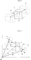
- Figure 5 is a schematic view illustrating a positional relationship of both the gamma-ray detectors and an image reconstruction area.
- Figure 6 is a graph illustrating coordinate systems of the both gamma-ray detectors and the image reconstruction area.
- the gamma-ray detectors 1a, 2a are assembles of minute scintillators a, b, respectively.
- An image reconstruction area S having the center coordinate OC is disposed between the gamma-ray detectors 1a, 2a.
- the center coordinate OC is specified by a vector VC starting from a mechanical origin OM of the apparatus.
- Vectors VA, VB extending from the mechanical origin OM of the apparatus to the center coordinates OA, OB of the gamma-ray detectors 1a, 2a, respectively, are determined in accordance with position data of the gamma-ray detectors 1a, 2a detected by a position sensor (not shown) and rotation angle data of the gamma-ray detectors 1a, 2a detected with an angle sensor (not shown).
- the vector uA is determined from information on the position and direction of the gamma-ray detectors 1a, 2a stored as the list mode data and the following Expression (3).
- the data on the position and the direction of the gamma-ray detectors 1a, 2a may be stored as tag information only when the position and the direction vary.
- uA R X ⁇ R Y ⁇ R Z ⁇ WA
- Rx, R Y , and Rz denote rotation of the gamma-ray detectors 1a, 2a about X-, Y-, and Z-axes, respectively, the axes being orthogonal to one another with reference to the mechanical origin OM of the apparatus
- T denotes a position in directions of the X-, Y-, and Z-axes (i.e., VA).
- the vector uB is determinable in the same manner as that for the vector uA.
- a list mode reconstruction algorithm of iterative approximation type is applicable to the determination of the line LOR (Line Of Response) connecting the scintillator elements a, b having detected the gamma-rays coincidently for every event.
- the update expression for obtaining an image with the list mode reconstruction algorithm is as the following Expression (4).
- the update Expression (4) is repeatedly performed to calculate an RI distribution image (distribution image of positron).
- Figure 7 is a schematic side view of an imaging mode with the PET apparatus.
- Figure 8 is a schematic side view of another imaging mode, different from that of Figure 7 , with the PET apparatus. Similar to the side view of Figure 1(b) , Figures 7 and 8 are each a side view of the PET apparatus seen reversely of Figure 1(a) , i.e., a side view seen from the head of a subject M.
- FIG. 2(a) the holding arms 3, 4 overlap one another completely, and ends of the detector units 1, 2 are adjacent to each other.
- the detector unit 1 is moved along with the holding arm 3 in the direction of arrow RA R (clockwise in the circumferential direction) in Figure 2(b)
- the detector unit 2 is moved along with the holding arm 4 in the direction of arrow RB L (counterclockwise in the circumferential direction).
- the detector units 1, 2 are moved in the vertical direction across the subject M so as to face to each other.
- the clockwise is a rotation direction seen from the subject M placed on his/her back on the top board 22, and the counterclockwise is a rotation direction seen from the subject M.
- the detector units 1, 2 face to each other in the vertical direction. From such a condition, the detector unit 1 is moved along with the holding arm 3 in the direction of arrow RA R (clockwise in the circumferential direction) in Figure 2(c) , and the detector unit 2 is moved along with the holding arm 4 in the direction of arrow RB R (clockwise circumferential direction). Thereafter, the detector units 1, 2 face to each other horizontally on both sides of the subject M.
- the holding arms 3, 4 slide in the direction of arrow RA (circumferential direction) or the direction of arrow RB (circumferential direction) at the same level without moving the lifting members 7, 8 vertically.
- the lifting members 7, 8 are moved independently in the vertical direction to change the levels of the holding arms 3, 4. Such may be adopted.
- FIGS 7(a) and 7(b) The following describes an imaging mode illustrated in Figures 7(a) and 7(b) .
- the holding arms 3, 4 overlap one another completely, and ends of the detector units 1, 2 are adjacent to each other.
- the detector unit 1 is moved along with the holding arm 3 in the direction of arrow RA R (clockwise in the circumferential direction) in Figure 7(a)
- the detector unit 2 is moved along with the holding arm 4 in the direction of arrow RB L (counterclockwise circumferential direction).
- the detector units 1, 2 are disposed vertically across the subject M so as to face to each other, as illustrated in Figure 7(a) .
- the detector units 1, 2 face to each other vertically. From such a condition, the arm holder 5, the holding arm 3, and the detector unit 1 are moved downward along with the lifting member 7 in a direction of arrow RC D (downward in the vertical direction) in Figure 7(b) , and the arm holder 6, the holding arm 4, and the detector unit 2 are moved upward along with the lifting member 8 in a direction of arrow RD U (upward in the vertical direction). Thereafter, the detector units 1, 2 are disposed close to the subject M in the vertical direction.
- the subject M is placed at the center of the detector units 1, 2 in Figures 1 , 2 , and 7 .
- the subject M may be placed close to the detector units 1, 2 radially.
- an imaging mode illustrated in Figures 8(a) and 8(b) only shown are the detector units 1, 2 and the subject M, and thus other elements are not shown.
- the ends of the detector units 1, 2 are adjacent to each other. From such a condition, the detector unit 1 is rotated by 90 degrees in the direction of arrow RA R (clockwise circumferential direction) in Figure 8(a) , and the detector unit 2 is rotated by 90 degrees in the direction of arrow RB R (clockwise in the circumferential direction). Thereafter, as illustrated in Figure 8(a) , the detector units 1, 2 are disposed above the subject M.
- the detector units 1, 2 are disposed above the subject M. From such a condition, the detector unit 1 is moved downward in the direction of arrow RC D (downward in the vertical direction) in Figure 8(b) , and the detector unit 2 is moved downward in the direction of arrow RD D (downward in the vertical direction). Accordingly, the subject M is accessible to the detector units 1, 2 radially.
- the detector units 1, 2 are not moved downward, but only the top board 22 (see Figures 1 , 2 , and 7 ) is moved upward, whereby the subject M on the top board 22 is moved upward to be accessible to the detector units 1, 2 radially.
- the detector units 1, 2 are moved downward, and the top board 22 is moved upward, whereby the subject M is accessible to the detector units 1, 2 radially.
- the imaging mode in Figure 8 in which the detector units 1, 2 are disposed above the subject M is not limitative.
- the following modes are applicable. That is, the detector units 1, 2 are disposed below the subject M.
- the detector units 1, 2 are disposed on either a left side or a right side of the subject M. In such modes, the subject M may be accessible to the detector units 1, 2 radially in the same manner.
- the PET apparatus of the present embodiment mentioned above includes a plurality of detector units (two detector units 1, 2 in the present embodiment) on a part of the arc of the circle surrounding the subject M, and a plurality of holding arms (two holding arms 3, 4 in the present embodiment) each disposed on the arc and holding the detector units 1, 2, respectively.
- the holding arms 3, 4 are moved independently along the circle surrounding the subject M, whereby the detector units 1, 2 are moved.
- the detector units 1, 2 are each disposed on the arc, and the holding arms 3, 4 are each disposed on the arc. Accordingly, the detector units 1, 2 are held entirely along the holding arms 3, 4. In the present embodiment, the detector unit 1 is entirely held along the holding arm 3, and the detector unit 2 is entirely held along the holding arm 4.
- the detector units 1, 2 are not cantilevered, causing a stable hold of the detector units 1, 2. This results in less swing of the detector units 1, 2.
- the detector units 1, 2 are each disposed on the arc surrounding the subject M. Accordingly, there is no need for a mechanism of changing and controlling inclination angles.
- the detector units are disposed individually depending on a focused imaging area. This can produce another effect of enlarging a stereo angle surrounding the imaging area.
- the present embodiment further includes the distance changing mechanism 30 changing the distance between the adjacent detector units 1, 2, by moving the detector units 1, 2 and the holding arms 3, 4 in one direction (the circumferential direction or the vertical direction in the present embodiment).
- the distance changing mechanism 30 reduces the distance between the adjacent detector units 1, 2 (e.g., reduces the distance from that in the imaging mode in Figure 7(a) to that in the imaging mode in Figure 7(b) ). This allows an enlarged stereo angle surrounding the subject M.
- reduction in distance between the adjacent detector units 1, 2 causes approach of the detector units 1, 2 to the subject M, achieving enhanced sensitivity of the detectors.
- the detector units 1, 2 and the holding arms 3, 4 are attached to the transportable carriage 9, and the detector units 1, 2 surround the mount table (bed 20 in the present embodiment) supporting the subject M placed thereon.
- the PET apparatus can image the subject placed on the mount table (e.g., bed 20 in the present embodiment) of the existing apparatus (e.g., a modality apparatus such as an X-ray CT apparatus).
- the present invention is not limited to the embodiment mentioned above, but may be modified as under.
- an anti-collision mechanism 50 as illustrated in Figure 10 is provided to prevent collision of the detector unit with the holding arm caused by operation of the distance changing mechanism. Such a mechanism can prevent the collision from occurring.
- the anti-collision mechanism 50 may be formed by a mechanical mechanism, a mechanism as illustrated in Figure 10(a) , a mechanism as illustrated in Figure 10(b) that electrically controls positions, or a mechanism in combination of the above mechanisms.
- the anti-collision mechanism 50 corresponds to the anti-collision mechanism in the present invention.
- the lifting member 7 includes a protrusion 51 on a lower end thereof.
- the holding arm 3 (not shown in Figure 10(a) ) contacts the detector unit 2 (not shown in Figure 10(a) )
- the holding arm 4 (not shown in Figure 10(a) ) contacts the detector unit 1 (not shown in Figure 10(a) )
- the lifting member 7 and the lifting member 8 are disposed at the same level. From such a condition, the lifting member 7 is moved upward or the lifting member 8 is moved downward, and correspondingly the detector unit 1 and the holding arm 3 are moved upward, or the detector unit 2 and the holding arm 4 are moved downward.
- the holding arm 3 collides against the detector unit 2
- the holding arm 4 collides against the detector unit 1.
- the above protrusion 51 provided so as to prevent the lifting member 7 above the lifting member 8 contacts the lifting member 8 immediately before the lifting member 7 is located above the lifting member 8. This allows mechanical stop of the lifting members 7, 8.
- the anti-collision mechanism 50 performing positional control electrically includes a position detecting mechanism 52, such as a potentiometer.
- the position detecting mechanism 52 are attached to each of the detector units, the holding arms, or the lifting members.
- the positions of the detector units, the holding arms, or the lifting members are detected, and detection results by the position detecting mechanism 52 are transmitted to a controller 53 formed by a central processing unit (CPU) and the like.
- the controller 53 controls the distance changing mechanism 30 to stop driving, whereby the collision is prevented from occurring.
Description
- The present invention relates to a positron CT apparatus that detects radiation emitted from positron radiopharmaceutical administered to a subject and generates a distribution image of positrons as an image. More particularly, the present invention is directed to a technique of imaging a human body for a subject.
- A positron CT apparatus, i.e., a PET (Positron Emission Tomography) apparatus reconstructs a tomographic image of a subject only upon simultaneous detection (i.e., coincidence counting) of two gamma-rays generated through annihilation of a positive electron (Positron) with a plurality of detectors. Specifically, the radiopharmaceutical containing positron-emitting radionuclide is administered to the subject. Then pair annihilation gamma-rays of 511Kev emitted from the administered subject are detected with detectors each formed by groups of many detector elements (e.g., scintillators). Thereafter, when gamma-rays are detected with two detectors within a certain time period, the gamma-rays are detected "coincidently", and are counted as pair annihilation gamma-rays. Moreover, a line (LOR: Line Of Response) is identified that connects the two detectors that detect positions where the pair annihilation gamma-rays are generated. Then information on coincidence that is detected in such a manner is stored for reconstruction, whereby a positron-emitting radionuclide image (i.e., a tomographic image) is obtained.
- In recent years, such an apparatus has a trend to conduct a diagnosis by superimposing the tomographic image obtained by the PET apparatus on a shape image obtained by another type of modality apparatus. Accordingly, the number of apparatus such as a PET/CT apparatus has increased in which a plurality of PET apparatus and modality apparatus accept a mount table (e.g., bed) supporting the subject placed thereon.
- However, addition of a new modality apparatus to the existing modality apparatus is difficult in terms of constraint of the bed. As a result, new purchase of a plurality of PET apparatus or modality apparatus is required. Accordingly, the present Applicant has suggested another type of PET apparatus. See Japanese Patent No.
4650324 - With the PET apparatus, the bed of the existing modality apparatus (e.g., X-ray CT apparatus) is commonly used and the carriage is transported close to the modality apparatus. This allows arrangement of the detector units adjacent to the modality apparatus. Consequently, additional arrangement of the PET apparatus to the existing modality apparatus is performable without new purchase of a plurality of PET apparatus and modality apparatus.
- As illustrated in
Figure 11 , the PET apparatus includes two holding arms A1, A2 (a first C-shape arm, and a second C-shape arm) in an arc shape. The holding arms include at tips thereof detector units U1, U2 (a first gamma-ray detector, and second gamma-ray detector), respectively. The two holding arms A1, A2 move independently along a circle surrounding the subject M, thereby changing inclination angles of the detector units U1, U2 such that surfaces of the detector units U1, U2 into which gamma-rays enter face to each other across the subject M. Such a configuration allows variation in distance between the detector units U1, U2 depending on a size of the subject M while the inclination angles are changed as illustrated inFigures 11(a) and 11(b) . This achieves radiography while the detector units U1, U2 face to each other. - [Patent Literature 1] Japanese Patent No.
4650324 -
JP 2007 263865 A JP H11 285492 A FR 2 697 918 A1 - However, the apparatus having the configuration of
Figure 11 possesses the following drawback. That is, as illustrated inFigure 11 , the detector units U1, U2 are mounted on the tips of the holding arms A1, A2, respectively. In other words, the detector units U1, U2 are cantilevered. As a result, the detector units U1, U2 are likely to swing. Moreover, a mechanism is required that changes and controls the inclination angles. This causes a complicated configuration. - The present invention has been made regarding the state of the art noted above, and its object is to provide a positron CT apparatus with detector units unlikely to swing and thus achieves a simple configuration.
- The present invention adopts the following construction for overcoming the above drawback. One embodiment of the present invention discloses a positron CT apparatus that performs radiography by detecting radiation emitted from positron radiopharmaceutical administered to a subject. The positron CT apparatus includes a plurality of detector units each disposed on a part of an arc of a circle surrounding the subject, and a plurality of holding arms each disposed on the arc and holding the detector units individually. The holding arms moves along the circle surrounding the subject independently, thereby causing the detector units to move.
- [Operation and Effect] With the embodiment of the positron CT apparatus, a plurality of detector units and a plurality of holding arms are provided. The detector units are each disposed on a part of the arc of the circle surrounding the subject. The holding arms each disposed on the arc hold the detector units individually. Here, the number of detector units is not necessarily equal to that of holding arms. The holding arms moves independently along the circle surrounding the subject, thereby causing the detector units to move. The detector units are each disposed on the arc, and the holding arms are also each disposed on the arc. Accordingly, the detector units are entirely held along the holding arms.
- Consequently, the detector units are not cantilevered, causing a stable hold of the detector units. This results in less swing of the detector units. Moreover, the detector units are each disposed on the arc surrounding the subject. Accordingly, there is no need for a mechanism of changing and controlling inclination angles. This achieves a simple configuration.
- Moreover, the detector units are disposed individually depending on a focused imaging area. This can produce another effect of enlarging a stereo angle surrounding the imaging area.
- Moreover, it is preferable that the positron CT apparatus further includes a distance changing mechanism changing a distance between the adjacent detector units by moving the detector units and the holding arms in one direction. Especially, the distance changing mechanism reduces the distance between the adjacent detector units. This allows a more enlarged stereo angle surrounding the subject. Moreover, reduction in distance between the adjacent detector units causes the detector units to be close to the subject, achieving enhanced sensitivity of the detectors.
- Moreover, it is preferable that an anti-collision mechanism is provided that prevents collision of the detector units with the holding arms caused by operation of the distance changing mechanism. For instance, when two detector units and two holding arms are provided, it is assumed that a first holding arm holds a first detector unit, and a second holding arm holds a second detector unit. The distance changing mechanism moves the detector units and the holding arms for changing a distances between the detector units. This may cause collision of the first holding arm with the second detector unit, or collision of the second holding arm with the first detector unit. Accordingly, the anti-collision mechanism is provided that prevents the collision of the detector unit with the holding arm caused by the operation of the distance changing mechanism. The mechanism can prevent the collision from occurring. Here, the anti-collision mechanism may be formed by a mechanical mechanism, a mechanism that electrically controls positions, or a mechanism in combination of the above mechanisms.
- As mentioned above, one embodiment of the positron CT apparatus according to the present invention is configured such that the detector units and the holding arms are attached to the transportable carriage, and the detector units surround a mount table supporting the subject placed thereon. Such a configuration allows movement of the detector units and incorporation of the transportable the carriage. Consequently, the positron CT apparatus can image the subject placed on the mount table (e.g., bed) of the existing apparatus.
- With the embodiment of the positron CT apparatus, a plurality of detector units and a plurality of holding arms are provided. The detector units are each disposed on a part of the arc of the circle surrounding the subject. The holding arms each disposed on the arc hold the detector units individually. The holding arms move independently along the circle surrounding the subject, thereby causing the detector units to move. This causes less swing of the detector units, achieving a simple configuration.
-
-
Figure 1 is a schematic side view of a PET (Positron Emission Tomography) apparatus and a schematic front view of detector units and holding arms according to one embodiment of the present invention. -
Figure 2 is a schematic perspective view of the PET apparatus according to the embodiment. -
Figure 3 schematically illustrates gamma-ray detectors in the detector unit. -
Figure 4 schematically illustrates one of the gamma-ray detectors. -
Figure 5 is a schematic view of a positional relationship between the gamma-ray detectors and an image reconstruction area. -
Figure 6 is a graph illustrating a coordinate system of the gamma-ray detectors and the image reconstruction area. -
Figure 7 is a schematic side view of an imaging mode by the PET apparatus. -
Figure 8 is a schematic side view of another imaging mode by the PET apparatus that differs from the mode inFigure 7 . -
Figure 9 is a schematic side view of a PET apparatus according to one modification of the present invention. -
Figure 10 is a schematic sectional view of an anti-collision mechanism. -
Figure 11 schematically illustrates a currently-used PET apparatus. - The following describes embodiments of the present invention with reference to drawings.
Figures 1(a) and 1(b) are a schematic side view of a PET (Positron Emission Tomography) apparatus and a schematic front view of detector units and holding arms according to one embodiment of the present invention.Figures 2(a) to 2(c) are each a schematic perspective view of the PET apparatus according to the embodiment. Note thatFigure 1(b) is a side view of the PET apparatus seen reversely ofFigure 1(a) , i.e., a side view seen from the head of a subject M. - As illustrated in
Figures 1 and2 , the PET apparatus according to the present embodiment includes twodetector units arms detector units arms arm 3 holds thedetector unit 1. The holdingarm 4 holds thedetector unit 2. Thedetector units arms - The PET apparatus further includes two
arm holders members transportable carriage 9. Thearm holders arms arm 3 is slidable relative to thearm holder 5 in a direction of arrow RA (circumferential direction). The holdingarm 4 is slidable relative to thearm holder 6 in a direction of arrow RB (circumferential direction). Thecarriage 9 corresponds to the carriage in the present invention. - The above configuration of the holding
arms arms arm 3, thedetector unit 1 held on the holdingarm 3 is moved in the same direction of arrow RA (circumferential direction). Moreover, in association with the movement of the holdingarm 4, thedetector unit 2 held on the holdingarm 4 is moved in the same direction of arrow RB (circumferential direction). - As mentioned above, independent movement of the holding
arms detector units detector unit 1 and the holdingarm 3 as well as combination of thedetector unit 2 and the holdingarm 4 are independently moved. Accordingly, in the drawing, the combination of thedetector unit 1 and the holdingarm 3 is denoted by dotted hatching, and the combination of thedetector unit 2 and the holdingarm 4 is denoted by dark gray fills for convenience. - The lifting
members arm holders member 7 is vertically movable relative to thecarriage 9 in a direction of arrow RC (vertical direction, seeFigure 1(a) ). The liftingmember 8 is vertically movable relative to thecarriage 9 in a direction of arrow RD (vertical direction, seeFigure 1(b) ). - Such a configuration of the
lifting members arm holders member 7, thearm holder 5 held on the liftingmember 7 is moved in the direction of arrow RC (vertical direction). In addition, the holdingarm 3 held on thearm holder 5 as well as thedetector unit 1 held on the holdingarm 3 are also moved in the direction of arrow RC (vertical direction). Moreover, in association with the movement of the liftingmember 8, thearm holder 6 held on the liftingmember 8 is moved in the same direction of arrow RD (vertical direction). In addition, the holdingarm 4 held on thearm holder 6 as well as thedetector unit 2 held on the holdingarm 4 are also moved in the same direction of arrow RD (vertical direction). - The
carriage 9 includes on a bottom thereof arear wheel 10 and afront wheel 11. These wheels are moved on the floor, whereby thecarriage 9 is transportable. Thefront wheel 11 is connected to a motor (not shown) via a driving shaft (not shown). The motor drives, and correspondingly thefront wheel 11 drives. An operator rotates therear wheel 10 by pushing and pulling thecarriage 9 at a rear side thereof in any directions. This allows movement of thecarriage 9 on the floor in any directions. Consequently, transporting thecarriage 9 to a side close to an existing apparatus (e.g., a modality apparatus such as an X-ray CT apparatus) allows arrangement of thedetector units - The existing apparatus is provided with a
bed 20 external to the PET apparatus. Thebed 20 includes a base 21 (not shown inFigure 1 ), and atop board 22. Thebase 21 is disposed on the floor. Thebase 21 is extendable vertically, thereby changing a level of thetop board 22 held on thebase 21. Thetop board 22 supports the subject M placed thereon. Thetop board 22 is movable horizontally relative to thebase 21. - The PET apparatus further includes a distance changing mechanism 30 (only shown in
Figure 1(a) ). Thedistance changing mechanism 30 movesdistance units arms detector units Figure 1(a) , thedistance changing mechanism 30 is only connected to the liftingmember 7. However, in the present embodiment, thedistance changing mechanism 30 is actually connected also to thearm holders member 8. Thedistance changing mechanism 30 is formed by a motor, a driving shaft, a gear, and a rack (each of them not shown). Thedistance changing mechanism 30 corresponds to the distance changing mechanism in the present invention. - In order to slide the holding
arm 3 relative to thearm holder 5 in the direction of arrow RA (circumferential direction) with thedistance changing mechanism 30, the motor, the driving shaft, and the gear are attached to thearm holder 5, and an arc-shaped rack is attached to the holdingarm 3. Driving the motor causes the gear to drive via the driving shaft, and accordingly, causes the arc-shaped rack engaged with the gear to drive, thereby causing the holdingarm 3 to slide relative to thearm holder 5 in the direction of arrow RA (circumferential direction). The same is applied for slide of the holdingarm 4 relative to thearm holder 6 in the direction of arrow RB (circumferential direction) with thedistance changing mechanism 30. - The
distance changing mechanism 30 does not necessarily have such a configuration as above. For instance, thedistance changing mechanism 30 is formed by a motor, a driving shaft, a gear, and a belt. The belt winds the holdingarm 3. Driving the motor causes the gear to drive via a driving shaft. Winding of the belt engaged with the gear causes the holdingarm 3 to slide relative to thearm holder 5 in the direction of arrow RA (circumferential direction). Such a configuration may be adopted. - In order to move the lifting
member 7 relative to thecarriage 9 vertically in the direction of arrow RC (vertical direction) with thedistance changing mechanism 30, the motor, the driving shaft, and the gear are attached to thecarriage 9, and a flat rack is attached to the liftingmember 7. Driving the motor causes the gear to drive via the driving shaft, and accordingly causes the flat rack engaged with the gear to drive, thereby causing the liftingmember 7 to move vertically relative to thecarriage 9 in the direction of arrow RC (vertical direction). The same is applied for movement of the liftingmember 8 vertically relative to thecarriage 9 in the direction of arrow RD (vertical direction) with thedistance changing mechanism 30. - The
distance changing mechanism 30 does not necessarily have such a configuration as above. For instance, thedistance changing mechanism 30 is formed by a motor, a driving shaft, a screw shaft, and a guide member. The liftingmember 7 is slidably attached to the guide member. Driving the motor causes the screw shaft to rotate via the driving shaft. Rotation of the screw shaft causes the liftingmember 7 to move vertically relative to the guide member in the direction of arrow RC (vertical direction), thereby causing the lifting member 7 t move vertically relative to thecarriage 9 in the direction of arrow RC direction (vertical direction). Such a configuration may be adopted. - As noted above, the
distance changing mechanism 30 causes the holdingarms arm holders lifting members carriage 9. Moreover, thedistance changing mechanism 30 causes thearm holders arms arms detector units - Scintillator blocks (not shown in
Figures 1 and2 ) of the gamma-ray detectors Figures 5 and 6 ) convert gamma-rays into light. The gamma-rays are generated from the subject M to which the radiopharmaceutical is administered. Then photomultipliers (PMT: Photo Multiplier Tube) (not shown inFigure1 and2 ) in the gamma-ray detectors - Specifically, when the radiopharmaceutical is administered to the subject M, a positron of a positron-emission type RI (radioactive isotope) annihilates to generate two gamma-ray beams. The coincidence circuit checks positions of the scintillator blocks and an incidence timing of the gamma-ray beams. Only when the gamma-ray beams coincidently enter into two scintillator blocks facing to each other across the subject M, it is determined that the transmitted image information is valid data. When the gamma-ray beam enters into only one of the scintillator blocks, the coincidence circuit is invalid. That is, the coincidence circuit detects coincident observation of the gamma-ray beams in the two gamma-
ray detectors - The image information transmitted to the coincidence circuit is determined as projection data. The projection data is reconstructed to generate a tomographic image (RI distribution image).
- The following describes a concrete configuration of the
detector units Figures 3 and 4. Figure 3 schematically illustrates gamma-ray detectors in the detector unit.Figure 4 is a schematic perspective view of one of the gamma-ray detectors. InFigures 3 and 4 , thedetector unit 1 is representatively illustrated. Since thedetector unit 2 has the same configuration as that of thedetector unit 1, the description thereof is to be omitted. In addition, a DOI detector is described as one example of the gamma-ray detector that allows discrimination of a position in a depth direction (DOI: Depth of Interaction) where interaction occurs. - As illustrated in
Figure 3 , a plurality of gamma-ray detectors 1a is unitized in arc to form adetector unit 1. As illustrated inFigures 3 and 4 , the gamma-ray detector 1a includes ascintillator block 1A, alight guide 1B optically coupled to thescintillator block 1A, and aphotomultiplier 1C (hereinafter, simply abbreviated to "PMT") optically coupled to thelight guide 1B. Thescintillator block 1A is formed by scintillator elements. The scintillator elements glow in association with incident gamma-rays, thereby converting the gamma-rays into light. With the conversion, the scintillator elements detect gamma-rays. The light glowing in the scintillator elements diffuses sufficiently in thescintillator block 1A, and the light enters into aPMT 1C through thelight guide 1B. ThePMT 1C multiplies and converts the light in thescintillator block 1A into an electric signal. The electric signal is transmitted to the coincidence circuit (not shown) as the image information (pixel value) mentioned above. - As illustrated in
Figure 4 , the gamma-ray detector 1a is composed of scintillator elements disposed three-dimensionally. Accordingly, the gamma-ray detector 1a is a DOI detector formed by a plurality of layers in the depth direction.Figures 3 and 4 each illustrate a four-layered DOI detector. However, the number of layers is not particularly limited as long as the number is plural. Moreover, the gamma-ray detector is not necessarily a DOI detector. Alternatively, the gamma-ray detector may be formed by only one-layered scintillator elements. - As mentioned above, the distance changing mechanism 30 (see
Figure 1 ) changes the distance between thedetector units ray detectors ray detector 2a of thedetector unit 2, seeFigures 5 and 6 ) vary constantly. Radiography is performed while thedetector units Figure 2 (b) ), or in the horizontal direction (seeFigure 2 (c) ), or while thedetector units Figure 7(b) ) depending on an imaging attitude or a size of the subject M. This causes an increased dose of gamma-rays detected in the gamma-ray detectors ray detectors ray detectors - The following describes a reconstruction algorithm with reference to
Figures 5 and 6 upon variation in position and direction of the gamma-ray detectors Figure 5 is a schematic view illustrating a positional relationship of both the gamma-ray detectors and an image reconstruction area.Figure 6 is a graph illustrating coordinate systems of the both gamma-ray detectors and the image reconstruction area. - As illustrated in
Figures 5 and 6 , the gamma-ray detectors ray detectors ray detectors ray detectors ray detectors - Consequently, when such phenomenon (hereinafter, abbreviated to "event" where appropriate) occurs as gamma-rays emitted from the subject M are coincidently counted, vectors uA, uB extending from the mechanical origin OM of the apparatus to scintillator elements a, b, respectively, having detected gamma-rays coincidently are given by the following Expressions (1) and (2):


- Moreover, when the phenomenon (event) occurs that the gamma-rays emitted from the subject M are coincidently counted, address pair data of the scintillator elements a, b having detected the gamma-rays, and address pair data of the vectors uA, uB of the scintillator elements a, b having detected the gamma-rays is collected and stored for every event as list mode data. On the other hand, a line LOR (Line Of Response) connecting the scintillator elements a, b having detected the gamma-rays coincidently is determined for every event from the address pair data of the vectors uA, uB that is collected and stored as the list mode data. Here, positron-emitting radionuclide lies on the line LOR.
- The vector uA is determined from information on the position and direction of the gamma-
ray detectors ray detectors 
ray detectors 
- As noted above, a list mode reconstruction algorithm of iterative approximation type is applicable to the determination of the line LOR (Line Of Response) connecting the scintillator elements a, b having detected the gamma-rays coincidently for every event. See, Non- Patent Literature Reader et al 1998 Phys. Med Bial.43 835-846. The update expression for obtaining an image with the list mode reconstruction algorithm is as the following Expression (4). The update Expression (4) is repeatedly performed to calculate an RI distribution image (distribution image of positron).
Mathematical Formula 2
where fk j denotes a pixel value of a pixel j upon k-th repeat, aij denotes the probability that a gamma-ray from the pixel j is detected by an LORi, M denotes the determined number of events, and I denotes the total number of LOR under the present radiographic condition (gamma-ray detector arrangement). Here, the update expression applicable to the present embodiment and used for the image reconstruction algorithm is not limited to the Expression (4). The image reconstruction algorithm is a known method referred to as an "iterative approximation method", and thus the detailed description thereof is to be omitted. - The following describes a concrete imaging mode of the PET apparatus with reference to
Figures 7 and9 along withFigure 2 mentioned above.Figure 7 is a schematic side view of an imaging mode with the PET apparatus.Figure 8 is a schematic side view of another imaging mode, different from that ofFigure 7 , with the PET apparatus. Similar to the side view ofFigure 1(b) ,Figures 7 and8 are each a side view of the PET apparatus seen reversely ofFigure 1(a) , i.e., a side view seen from the head of a subject M. Consequently, when thelifting members arm holders arm holder 6 and the liftingmember 8 remain hidden and only thearm holder 5 and the liftingmember 7 are visible inFigure 1(a) , whereas thearm holder 5 and the liftingmember 7 remain hidden and only thearm holder 6 and the liftingmember 8 are visible inFigure 7(a) . - The following firstly describes an imaging mode illustrated in
Figures 2(a) to 2(c) . As illustrated inFigure 2(a) , the holdingarms detector units detector unit 1 is moved along with the holdingarm 3 in the direction of arrow RAR (clockwise in the circumferential direction) inFigure 2(b) , and thedetector unit 2 is moved along with the holdingarm 4 in the direction of arrow RBL (counterclockwise in the circumferential direction). Then, thedetector units top board 22, and the counterclockwise is a rotation direction seen from the subject M. - In contrast to this, as illustrated in
Figure 2(b) , thedetector units detector unit 1 is moved along with the holdingarm 3 in the direction of arrow RAR (clockwise in the circumferential direction) inFigure 2(c) , and thedetector unit 2 is moved along with the holdingarm 4 in the direction of arrow RBR (clockwise circumferential direction). Thereafter, thedetector units - In the imaging mode illustrated in
Figures 2(a) to 2(c) , the holdingarms lifting members Figures 7(a) and 7(b) , the liftingmembers arms - The following describes an imaging mode illustrated in
Figures 7(a) and 7(b) . As illustrated inFigure 2(a) , the holdingarms detector units detector unit 1 is moved along with the holdingarm 3 in the direction of arrow RAR (clockwise in the circumferential direction) inFigure 7(a) , and thedetector unit 2 is moved along with the holdingarm 4 in the direction of arrow RBL (counterclockwise circumferential direction). Then, similar to the mode inFigure 2(b) , thedetector units Figure 7(a) . - Moreover, as illustrated in
Figure 7(a) , thedetector units arm holder 5, the holdingarm 3, and thedetector unit 1 are moved downward along with the liftingmember 7 in a direction of arrow RCD (downward in the vertical direction) inFigure 7(b) , and thearm holder 6, the holdingarm 4, and thedetector unit 2 are moved upward along with the liftingmember 8 in a direction of arrow RDU (upward in the vertical direction). Thereafter, thedetector units - The subject M is placed at the center of the
detector units Figures 1 ,2 , and7 . Alternatively, as illustrated inFigure 8(b) , the subject M may be placed close to thedetector units Figures 8(a) and 8(b) , only shown are thedetector units Figure 2(a) , the ends of thedetector units detector unit 1 is rotated by 90 degrees in the direction of arrow RAR (clockwise circumferential direction) inFigure 8(a) , and thedetector unit 2 is rotated by 90 degrees in the direction of arrow RBR (clockwise in the circumferential direction). Thereafter, as illustrated inFigure 8(a) , thedetector units - Moreover, as illustrated in
Figure 8(a) , thedetector units detector unit 1 is moved downward in the direction of arrow RCD (downward in the vertical direction) inFigure 8(b) , and thedetector unit 2 is moved downward in the direction of arrow RDD (downward in the vertical direction). Accordingly, the subject M is accessible to thedetector units detector units Figures 1 ,2 , and7 ) is moved upward, whereby the subject M on thetop board 22 is moved upward to be accessible to thedetector units detector units top board 22 is moved upward, whereby the subject M is accessible to thedetector units Figure 8 in which thedetector units detector units detector units detector units - The PET apparatus of the present embodiment mentioned above includes a plurality of detector units (two
detector units arms detector units arms detector units detector units arms detector units arms detector unit 1 is entirely held along the holdingarm 3, and thedetector unit 2 is entirely held along the holdingarm 4. - Consequently, the
detector units detector units detector units detector units - Moreover, the detector units are disposed individually depending on a focused imaging area. This can produce another effect of enlarging a stereo angle surrounding the imaging area.
- Moreover, it is preferable that the present embodiment further includes the
distance changing mechanism 30 changing the distance between theadjacent detector units detector units arms distance changing mechanism 30 reduces the distance between theadjacent detector units 1, 2 (e.g., reduces the distance from that in the imaging mode inFigure 7(a) to that in the imaging mode inFigure 7(b) ). This allows an enlarged stereo angle surrounding the subject M. Moreover, reduction in distance between theadjacent detector units detector units - In the present embodiment, the
detector units arms transportable carriage 9, and thedetector units bed 20 in the present embodiment) supporting the subject M placed thereon. Such a configuration allows movement of thedetector units carriage 9. Consequently, the PET apparatus can image the subject placed on the mount table (e.g.,bed 20 in the present embodiment) of the existing apparatus (e.g., a modality apparatus such as an X-ray CT apparatus). - The present invention is not limited to the embodiment mentioned above, but may be modified as under.
- (1) In the embodiment mentioned above, a human body has been described as one example of the subject. Alternatively, the present invention is applicable to a positron CT apparatus (PET apparatus) that images small animals (e.g., mice).
- (2) In the embodiment mentioned above, the positron CT apparatus (PET apparatus) imaging a whole human body has been described. However, an imaging object is not limited to the whole body. That is, the present invention is applicable to a PET apparatus that images the head of a subject, or a mammography PET apparatus that images the breast of a subject.
- (3) In the embodiment mentioned above, two detector units and two holding arms are provided. However, the number thereof is not limited to two as long as the number is plural. That is, three or more detector units and three or more holding arms may be adopted. Moreover, the number of detector units is not necessarily the same as that of holding arms as long as a plurality of detector units are each disposed on a part of the arc, and the holding arms are each disposed on the arc to move independently for moving the detector units.
- (4) In the embodiment mentioned above, both the detector units and the holding arms are each disposed on a part of the arc. However, the holding arms may be arranged integratedly in a circular shape. For instance, as illustrated in
Figure 9 , holding arms 41, 42 in a circular rail shape are disposed (one of the holding arms 41, 42 is disposed in front of the other of the holding arms 41, 42), and agantry 43 holds the holding arms 41, 42. The holding arm 41 is moved in a direction of arrow RE (circumferential direction), and correspondingly thedetector unit 1 held with the holding arm 41 is moved in the same direction of arrow RE (circumferential direction). Moreover, the holding arm 42 is moved in a direction of arrow RF (circumferential direction), and correspondingly thedetector unit 2 held with the holding arm 42 is moved in the same direction of arrow RF (circumferential direction). Here, thedetector units detector units - (5) In the embodiment mentioned above, the
detector units arms detector units - (6) In the embodiment mentioned above, the detector units and the holding arms are attached to the transportable carriage, and the detector units surround the mount table of the existing apparatus. However, it is not always necessary to attach the detector units and the holding arms to the transportable carriage. Alternatively, the present invention is applicable to a PET apparatus having a base fixedly attached to the floor or the ceiling.
- (7) In the embodiment mentioned above, a single PET apparatus has been described. Alternatively, the present invention is applicable to an apparatus in combination of the PET apparatus and another modality apparatus (e.g., X-ray CT apparatus).
- (8) An anti-collision mechanism is preferably provided that prevents collision of the detector units with the holding arms caused by operation of the distance changing mechanism 30 (see
Figure 1(a) ). As described in the embodiment above, when the two detector units and the two holding arms are provided, and a first holding arm 3 (seeFigure 1 ,2 , and7 ) holds a first detector unit 1 (seeFigure 1 ,2 , and7 ), and a second holding arm 4 (seeFigure 1 ,2 , and7 ) holds a second detector unit 2 (seeFigure 1 ,2 , and7 ), thedistance changing mechanism 30 changing the distance between thedetector units detector units arms arm 3 with thedetector unit 2 or collision of the holdingarm 4 with thedetector unit 1. Especially, the holdingarm 3 contacts thedetector unit 2, and the holdingarm 4contacts detector unit 1. From such a condition, when thedetector unit 1 and the holdingarm 3 are moved upward or thedetector unit 2 and the holdingarm 4 moved downward, the holdingarm 3 collides against thedetector unit 2 and the holdingarm 4 collides against thedetector unit 1. - Accordingly, an
anti-collision mechanism 50 as illustrated inFigure 10 is provided to prevent collision of the detector unit with the holding arm caused by operation of the distance changing mechanism. Such a mechanism can prevent the collision from occurring. Here, theanti-collision mechanism 50 may be formed by a mechanical mechanism, a mechanism as illustrated inFigure 10(a) , a mechanism as illustrated inFigure 10(b) that electrically controls positions, or a mechanism in combination of the above mechanisms. Theanti-collision mechanism 50 corresponds to the anti-collision mechanism in the present invention. - As illustrated in
Figure 10(a) , with theanti-collision mechanism 50 having a mechanical mechanism, the liftingmember 7 includes aprotrusion 51 on a lower end thereof. When the holding arm 3 (not shown inFigure 10(a) ) contacts the detector unit 2 (not shown inFigure 10(a) ), and the holding arm 4 (not shown inFigure 10(a) ) contacts the detector unit 1 (not shown inFigure 10(a) ), the liftingmember 7 and the liftingmember 8 are disposed at the same level. From such a condition, the liftingmember 7 is moved upward or the liftingmember 8 is moved downward, and correspondingly thedetector unit 1 and the holdingarm 3 are moved upward, or thedetector unit 2 and the holdingarm 4 are moved downward. As a result, the holdingarm 3 collides against thedetector unit 2, and the holdingarm 4 collides against thedetector unit 1. Theabove protrusion 51 provided so as to prevent the liftingmember 7 above the liftingmember 8 contacts the liftingmember 8 immediately before the liftingmember 7 is located above the liftingmember 8. This allows mechanical stop of thelifting members - Moreover, as illustrated in
Figure 10(b) , theanti-collision mechanism 50 performing positional control electrically includes aposition detecting mechanism 52, such as a potentiometer. Theposition detecting mechanism 52 are attached to each of the detector units, the holding arms, or the lifting members. The positions of the detector units, the holding arms, or the lifting members are detected, and detection results by theposition detecting mechanism 52 are transmitted to acontroller 53 formed by a central processing unit (CPU) and the like. Then, when receiving the position results immediately before collision from theposition detecting mechanism 52, thecontroller 53 controls thedistance changing mechanism 30 to stop driving, whereby the collision is prevented from occurring. -
- 1,2 ... detector unit
- 3, 4 ... holding arm
- 9 ... carriage
- 30 ... distance changing mechanism
- 50 ... anti-collision mechanism
Claims (10)
- A positron CT apparatus performing radiography by detecting radiation emitted from positron radiopharmaceutical administered to a subject (M), the positron CT apparatus comprising:a plurality of detector units (1, 2) each disposed on a part of an arc of a circle surrounding the subject (M),a plurality of holding arms (3, 4) each disposed on the arc and holding the detector units (1, 2) individually,the holding arms (3, 4) moving along the circle surrounding the subject (M) independently, thereby causing the detector units (1, 2) to move,arm holders (5, 6) holding the holding arms (3, 4) individually, characterised in that it further comprises a distance changing mechanism (30), wherein the distance changing mechanism (30) changes the distance between the adjacent detector units (1, 2) by moving the holding arms (3, 4) and the arm holders (5, 6) in a vertical direction (RC, RD).
- The positron CT apparatus according to claim 1, wherein
the distance changing mechanism (30) changes the distance between the adjacent detector units (1, 2) by moving the holding arms (3, 4) in a circumferential direction (RA, RB). - The positron CT apparatus according to claim 2, wherein
the distance changing mechanism (30) moves the holding arms (3, 4) in the circumferential direction (RA, RB) by sliding the holding arms (3, 4) relative to the arm holders (5, 6) in the circumferential direction (RA, RB). - The positron CT apparatus according to claims 1 to 3, further comprising:lifting members (7, 8) lifting the arm holders (5, 6) individually, whereinthe distance changing mechanism (30) moves the arm holders (5, 6) held with the lifting members (7, 8) and the holding arms (3, 4) held with the arm holders (5, 6) by moving the lifting members (7, 8) in the vertical direction (RC, RD).
- The positron CT apparatus according to any of claims 1 to 4, further comprising:an anti-collision mechanism (50) preventing collision of the detector units (1, 2) with the holding arms (3, 4) caused by operation of the distance changing mechanism (30).
- The positron CT apparatus according to claim 5, wherein
when the number of detector units (1, 2) is two and the number of holding arms (3, 4) is two, and a first holding arm (3) holds a first detector unit (1), and a second holding arm (4) holds a second detector unit (2), the anti-collision mechanism (50) prevents collision of the first holding arm (3) with the second detector unit (2), or collision of the second holding arm (4) with the first detector unit (1). - The positron CT apparatus according to claim 5 or 6, wherein
the anti-collision mechanism (50) is formed by a mechanical mechanism. - The positron CT apparatus according to any of claims 5 to 7, wherein
the anti-collision mechanism (50) is formed by a mechanism that electrically controls positions. - The positron CT apparatus according to claim 8, wherein
the anti-collision mechanism (50) includes
a position detecting mechanism (52) detecting positions of the detector units (1, 2) or mechanisms holding the detector units (1, 2) individually, and
a controller (53) controlling the anti-collision mechanism (50) in accordance with a positional detection result by the position detecting mechanism (52). - The positron CT apparatus according to any of claims 1 to 9, wherein
the detector units (1, 2) and the holding arms (3, 4) are attached to a transportable carriage (9), and the detector units (1, 2) surround a mount table (20) supporting the subject (M) placed thereon.
Applications Claiming Priority (2)
| Application Number | Priority Date | Filing Date | Title |
|---|---|---|---|
| JP2013017225 | 2013-01-31 | ||
| PCT/JP2014/051121 WO2014119428A1 (en) | 2013-01-31 | 2014-01-21 | Positron ct device |
Publications (3)
| Publication Number | Publication Date |
|---|---|
| EP2952932A1 EP2952932A1 (en) | 2015-12-09 |
| EP2952932A4 EP2952932A4 (en) | 2016-01-13 |
| EP2952932B1 true EP2952932B1 (en) | 2017-11-01 |
Family
ID=51262143
Family Applications (1)
| Application Number | Title | Priority Date | Filing Date |
|---|---|---|---|
| EP14746255.0A Not-in-force EP2952932B1 (en) | 2013-01-31 | 2014-01-21 | Positron ct apparatus |
Country Status (5)
| Country | Link |
|---|---|
| US (1) | US10349904B2 (en) |
| EP (1) | EP2952932B1 (en) |
| JP (2) | JP6024764B2 (en) |
| CN (1) | CN104919337B (en) |
| WO (1) | WO2014119428A1 (en) |
Families Citing this family (7)
| Publication number | Priority date | Publication date | Assignee | Title |
|---|---|---|---|---|
| EP3209208B1 (en) * | 2014-10-22 | 2019-12-04 | Carestream Health, Inc. | Mobile radiographic imaging apparatus |
| EP3494547B1 (en) * | 2016-08-03 | 2020-06-17 | Koninklijke Philips N.V. | Time-of-flight (tof) pet image reconstruction using locally modified tof kernels |
| CN108853751A (en) * | 2017-05-12 | 2018-11-23 | 南京中硼联康医疗科技有限公司 | Photon emits detection device and the boron neutron capture treatment system with it |
| JP6938757B2 (en) * | 2017-05-12 | 2021-09-22 | 南京中硼▲聯▼康医▲療▼科技有限公司Neuboron Medtech Ltd. | Photon emission detector and boron neutron capture therapy system with it |
| US10702223B2 (en) * | 2017-06-07 | 2020-07-07 | Epica International, Inc. | Imaging table for greater access to patient region of interest |
| US11712209B2 (en) | 2017-06-07 | 2023-08-01 | Epica International, Inc. | Imaging table for greater access to patient region of interest |
| US11375962B2 (en) * | 2019-08-05 | 2022-07-05 | Linev Systems, Inc. | Fast foreign object scanner for scanning human bodies |
Family Cites Families (8)
| Publication number | Priority date | Publication date | Assignee | Title |
|---|---|---|---|---|
| FR2677447A1 (en) * | 1991-06-07 | 1992-12-11 | Sopha Medical | GAMMA TOMOGRAPHIC CAMERA PROVIDED WITH AN ORIENTABLE DETECTOR. |
| FR2697918B1 (en) * | 1992-11-10 | 1994-12-30 | Gen Electric | Scintigraphy device. |
| JP3762539B2 (en) | 1998-04-03 | 2006-04-05 | 株式会社日立メディコ | X-ray fluoroscopic apparatus and method |
| JP2006055518A (en) * | 2004-08-23 | 2006-03-02 | Shimadzu Corp | X-ray diagnostic system |
| US8452381B2 (en) | 2004-12-17 | 2013-05-28 | Koninklijke Philips Electronics N.V. | Gantry system |
| JP4650324B2 (en) * | 2006-03-29 | 2011-03-16 | 株式会社島津製作所 | Nuclear medicine diagnostic equipment |
| WO2008035400A1 (en) * | 2006-09-19 | 2008-03-27 | Shimadzu Corporation | Nuclear medicine diagnosis system |
| JP5815218B2 (en) * | 2010-08-30 | 2015-11-17 | 株式会社東芝 | Radiotherapy apparatus, control method, and control program |
-
2014
- 2014-01-21 CN CN201480004947.8A patent/CN104919337B/en not_active Expired - Fee Related
- 2014-01-21 EP EP14746255.0A patent/EP2952932B1/en not_active Not-in-force
- 2014-01-21 WO PCT/JP2014/051121 patent/WO2014119428A1/en active Application Filing
- 2014-01-21 JP JP2014559638A patent/JP6024764B2/en active Active
- 2014-01-21 US US14/764,932 patent/US10349904B2/en not_active Expired - Fee Related
-
2016
- 2016-10-13 JP JP2016201859A patent/JP2017003603A/en active Pending
Non-Patent Citations (1)
| Title |
|---|
| None * |
Also Published As
| Publication number | Publication date |
|---|---|
| US10349904B2 (en) | 2019-07-16 |
| EP2952932A1 (en) | 2015-12-09 |
| WO2014119428A1 (en) | 2014-08-07 |
| CN104919337A (en) | 2015-09-16 |
| CN104919337B (en) | 2018-01-09 |
| US20150366519A1 (en) | 2015-12-24 |
| JP2017003603A (en) | 2017-01-05 |
| JP6024764B2 (en) | 2016-11-16 |
| JPWO2014119428A1 (en) | 2017-01-26 |
| EP2952932A4 (en) | 2016-01-13 |
Similar Documents
| Publication | Publication Date | Title |
|---|---|---|
| EP2952932B1 (en) | Positron ct apparatus | |
| US7693565B2 (en) | Method and apparatus for automatically positioning a structure within a field of view | |
| JP2006516742A (en) | Single photon emission computed tomography system | |
| WO2015019312A1 (en) | Pet system with crystal or detector unit spacing | |
| JP6298451B2 (en) | Image processing system and image processing method | |
| JP5195935B2 (en) | Radiation tomography equipment | |
| WO2010109523A1 (en) | Radiation tomography device | |
| JP5176355B2 (en) | Diagnostic equipment | |
| JP4817055B2 (en) | Mammography equipment | |
| JP2535762B2 (en) | Simultaneous Scattering Counting Method with Gamma Absorber in Positron Tomography Equipment and Positron Tomography Equipment | |
| EP1336869A2 (en) | Apparatus for forming radiation source distribution image | |
| US20110019895A1 (en) | Tomographic equipment, imaging system provided therewith, and imaging data acquisition method | |
| US8519341B2 (en) | Radiation tomography apparatus | |
| JP5262152B2 (en) | Diagnostic system | |
| JP3881403B2 (en) | Nuclear medicine diagnostic equipment | |
| JP2007212295A (en) | Nuclear medicine diagnostic equipment | |
| JPWO2020059135A1 (en) | Data processing methods, programs, data processing equipment and positron emission tomographic imaging equipment | |
| US11944479B2 (en) | Medical image diagnosis apparatus, x-ray computed tomography apparatus, and medical image diagnosis assisting method | |
| JPH10160848A (en) | Nuclear medicine diagnostic device | |
| JP2005114739A (en) | Nuclear medicine diagnostic equipment | |
| US20230284984A1 (en) | Pet apparatus, pet-ct apparatus, image generation and display method, and nonvolatile computer-readable storage medium storing image generation and display program | |
| JP6575682B2 (en) | Radiation tomography equipment | |
| JP4374983B2 (en) | Nuclear medicine imaging equipment | |
| JPH10160849A (en) | Nuclear medicine diagnostic device | |
| JP2005249412A (en) | Radioactivity imaging system |
Legal Events
| Date | Code | Title | Description |
|---|---|---|---|
| PUAI | Public reference made under article 153(3) epc to a published international application that has entered the european phase |
Free format text: ORIGINAL CODE: 0009012 |
|
| 17P | Request for examination filed |
Effective date: 20150813 |
|
| AK | Designated contracting states |
Kind code of ref document: A1 Designated state(s): AL AT BE BG CH CY CZ DE DK EE ES FI FR GB GR HR HU IE IS IT LI LT LU LV MC MK MT NL NO PL PT RO RS SE SI SK SM TR |
|
| AX | Request for extension of the european patent |
Extension state: BA ME |
|
| A4 | Supplementary search report drawn up and despatched |
Effective date: 20151215 |
|
| RIC1 | Information provided on ipc code assigned before grant |
Ipc: A61B 6/10 20060101ALI20151209BHEP Ipc: A61B 6/03 20060101ALI20151209BHEP Ipc: G01T 1/161 20060101AFI20151209BHEP Ipc: A61B 6/00 20060101ALI20151209BHEP |
|
| DAX | Request for extension of the european patent (deleted) | ||
| R17P | Request for examination filed (corrected) |
Effective date: 20150813 |
|
| GRAP | Despatch of communication of intention to grant a patent |
Free format text: ORIGINAL CODE: EPIDOSNIGR1 |
|
| RIC1 | Information provided on ipc code assigned before grant |
Ipc: A61B 6/10 20060101ALI20170509BHEP Ipc: A61B 6/03 20060101ALI20170509BHEP Ipc: G01T 1/161 20060101AFI20170509BHEP Ipc: A61B 6/00 20060101ALI20170509BHEP |
|
| INTG | Intention to grant announced |
Effective date: 20170601 |
|
| GRAS | Grant fee paid |
Free format text: ORIGINAL CODE: EPIDOSNIGR3 |
|
| GRAA | (expected) grant |
Free format text: ORIGINAL CODE: 0009210 |
|
| AK | Designated contracting states |
Kind code of ref document: B1 Designated state(s): AL AT BE BG CH CY CZ DE DK EE ES FI FR GB GR HR HU IE IS IT LI LT LU LV MC MK MT NL NO PL PT RO RS SE SI SK SM TR |
|
| REG | Reference to a national code |
Ref country code: GB Ref legal event code: FG4D |
|
| REG | Reference to a national code |
Ref country code: CH Ref legal event code: EP Ref country code: AT Ref legal event code: REF Ref document number: 942587 Country of ref document: AT Kind code of ref document: T Effective date: 20171115 |
|
| REG | Reference to a national code |
Ref country code: IE Ref legal event code: FG4D |
|
| REG | Reference to a national code |
Ref country code: DE Ref legal event code: R096 Ref document number: 602014016619 Country of ref document: DE |
|
| REG | Reference to a national code |
Ref country code: FR Ref legal event code: PLFP Year of fee payment: 5 |
|
| REG | Reference to a national code |
Ref country code: NL Ref legal event code: MP Effective date: 20171101 |
|
| REG | Reference to a national code |
Ref country code: LT Ref legal event code: MG4D |
|
| REG | Reference to a national code |
Ref country code: AT Ref legal event code: MK05 Ref document number: 942587 Country of ref document: AT Kind code of ref document: T Effective date: 20171101 |
|
| PG25 | Lapsed in a contracting state [announced via postgrant information from national office to epo] |
Ref country code: SE Free format text: LAPSE BECAUSE OF FAILURE TO SUBMIT A TRANSLATION OF THE DESCRIPTION OR TO PAY THE FEE WITHIN THE PRESCRIBED TIME-LIMIT Effective date: 20171101 Ref country code: LT Free format text: LAPSE BECAUSE OF FAILURE TO SUBMIT A TRANSLATION OF THE DESCRIPTION OR TO PAY THE FEE WITHIN THE PRESCRIBED TIME-LIMIT Effective date: 20171101 Ref country code: NL Free format text: LAPSE BECAUSE OF FAILURE TO SUBMIT A TRANSLATION OF THE DESCRIPTION OR TO PAY THE FEE WITHIN THE PRESCRIBED TIME-LIMIT Effective date: 20171101 Ref country code: FI Free format text: LAPSE BECAUSE OF FAILURE TO SUBMIT A TRANSLATION OF THE DESCRIPTION OR TO PAY THE FEE WITHIN THE PRESCRIBED TIME-LIMIT Effective date: 20171101 Ref country code: NO Free format text: LAPSE BECAUSE OF FAILURE TO SUBMIT A TRANSLATION OF THE DESCRIPTION OR TO PAY THE FEE WITHIN THE PRESCRIBED TIME-LIMIT Effective date: 20180201 Ref country code: ES Free format text: LAPSE BECAUSE OF FAILURE TO SUBMIT A TRANSLATION OF THE DESCRIPTION OR TO PAY THE FEE WITHIN THE PRESCRIBED TIME-LIMIT Effective date: 20171101 |
|
| PG25 | Lapsed in a contracting state [announced via postgrant information from national office to epo] |
Ref country code: RS Free format text: LAPSE BECAUSE OF FAILURE TO SUBMIT A TRANSLATION OF THE DESCRIPTION OR TO PAY THE FEE WITHIN THE PRESCRIBED TIME-LIMIT Effective date: 20171101 Ref country code: AT Free format text: LAPSE BECAUSE OF FAILURE TO SUBMIT A TRANSLATION OF THE DESCRIPTION OR TO PAY THE FEE WITHIN THE PRESCRIBED TIME-LIMIT Effective date: 20171101 Ref country code: LV Free format text: LAPSE BECAUSE OF FAILURE TO SUBMIT A TRANSLATION OF THE DESCRIPTION OR TO PAY THE FEE WITHIN THE PRESCRIBED TIME-LIMIT Effective date: 20171101 Ref country code: HR Free format text: LAPSE BECAUSE OF FAILURE TO SUBMIT A TRANSLATION OF THE DESCRIPTION OR TO PAY THE FEE WITHIN THE PRESCRIBED TIME-LIMIT Effective date: 20171101 Ref country code: BG Free format text: LAPSE BECAUSE OF FAILURE TO SUBMIT A TRANSLATION OF THE DESCRIPTION OR TO PAY THE FEE WITHIN THE PRESCRIBED TIME-LIMIT Effective date: 20180201 Ref country code: IS Free format text: LAPSE BECAUSE OF FAILURE TO SUBMIT A TRANSLATION OF THE DESCRIPTION OR TO PAY THE FEE WITHIN THE PRESCRIBED TIME-LIMIT Effective date: 20180301 Ref country code: GR Free format text: LAPSE BECAUSE OF FAILURE TO SUBMIT A TRANSLATION OF THE DESCRIPTION OR TO PAY THE FEE WITHIN THE PRESCRIBED TIME-LIMIT Effective date: 20180202 |
|
| PG25 | Lapsed in a contracting state [announced via postgrant information from national office to epo] |
Ref country code: SK Free format text: LAPSE BECAUSE OF FAILURE TO SUBMIT A TRANSLATION OF THE DESCRIPTION OR TO PAY THE FEE WITHIN THE PRESCRIBED TIME-LIMIT Effective date: 20171101 Ref country code: EE Free format text: LAPSE BECAUSE OF FAILURE TO SUBMIT A TRANSLATION OF THE DESCRIPTION OR TO PAY THE FEE WITHIN THE PRESCRIBED TIME-LIMIT Effective date: 20171101 Ref country code: CY Free format text: LAPSE BECAUSE OF FAILURE TO SUBMIT A TRANSLATION OF THE DESCRIPTION OR TO PAY THE FEE WITHIN THE PRESCRIBED TIME-LIMIT Effective date: 20171101 Ref country code: DK Free format text: LAPSE BECAUSE OF FAILURE TO SUBMIT A TRANSLATION OF THE DESCRIPTION OR TO PAY THE FEE WITHIN THE PRESCRIBED TIME-LIMIT Effective date: 20171101 Ref country code: CZ Free format text: LAPSE BECAUSE OF FAILURE TO SUBMIT A TRANSLATION OF THE DESCRIPTION OR TO PAY THE FEE WITHIN THE PRESCRIBED TIME-LIMIT Effective date: 20171101 |
|
| REG | Reference to a national code |
Ref country code: DE Ref legal event code: R097 Ref document number: 602014016619 Country of ref document: DE |
|
| PG25 | Lapsed in a contracting state [announced via postgrant information from national office to epo] |
Ref country code: IT Free format text: LAPSE BECAUSE OF FAILURE TO SUBMIT A TRANSLATION OF THE DESCRIPTION OR TO PAY THE FEE WITHIN THE PRESCRIBED TIME-LIMIT Effective date: 20171101 Ref country code: PL Free format text: LAPSE BECAUSE OF FAILURE TO SUBMIT A TRANSLATION OF THE DESCRIPTION OR TO PAY THE FEE WITHIN THE PRESCRIBED TIME-LIMIT Effective date: 20171101 Ref country code: SM Free format text: LAPSE BECAUSE OF FAILURE TO SUBMIT A TRANSLATION OF THE DESCRIPTION OR TO PAY THE FEE WITHIN THE PRESCRIBED TIME-LIMIT Effective date: 20171101 Ref country code: RO Free format text: LAPSE BECAUSE OF FAILURE TO SUBMIT A TRANSLATION OF THE DESCRIPTION OR TO PAY THE FEE WITHIN THE PRESCRIBED TIME-LIMIT Effective date: 20171101 |
|
| REG | Reference to a national code |
Ref country code: CH Ref legal event code: PL |
|
| PLBE | No opposition filed within time limit |
Free format text: ORIGINAL CODE: 0009261 |
|
| STAA | Information on the status of an ep patent application or granted ep patent |
Free format text: STATUS: NO OPPOSITION FILED WITHIN TIME LIMIT |
|
| 26N | No opposition filed |
Effective date: 20180802 |
|
| PG25 | Lapsed in a contracting state [announced via postgrant information from national office to epo] |
Ref country code: LU Free format text: LAPSE BECAUSE OF NON-PAYMENT OF DUE FEES Effective date: 20180121 |
|
| REG | Reference to a national code |
Ref country code: IE Ref legal event code: MM4A |
|
| REG | Reference to a national code |
Ref country code: BE Ref legal event code: MM Effective date: 20180131 |
|
| PG25 | Lapsed in a contracting state [announced via postgrant information from national office to epo] |
Ref country code: BE Free format text: LAPSE BECAUSE OF NON-PAYMENT OF DUE FEES Effective date: 20180131 Ref country code: SI Free format text: LAPSE BECAUSE OF FAILURE TO SUBMIT A TRANSLATION OF THE DESCRIPTION OR TO PAY THE FEE WITHIN THE PRESCRIBED TIME-LIMIT Effective date: 20171101 Ref country code: LI Free format text: LAPSE BECAUSE OF NON-PAYMENT OF DUE FEES Effective date: 20180131 Ref country code: CH Free format text: LAPSE BECAUSE OF NON-PAYMENT OF DUE FEES Effective date: 20180131 |
|
| PG25 | Lapsed in a contracting state [announced via postgrant information from national office to epo] |
Ref country code: IE Free format text: LAPSE BECAUSE OF NON-PAYMENT OF DUE FEES Effective date: 20180121 |
|
| PG25 | Lapsed in a contracting state [announced via postgrant information from national office to epo] |
Ref country code: MC Free format text: LAPSE BECAUSE OF FAILURE TO SUBMIT A TRANSLATION OF THE DESCRIPTION OR TO PAY THE FEE WITHIN THE PRESCRIBED TIME-LIMIT Effective date: 20171101 |
|
| PG25 | Lapsed in a contracting state [announced via postgrant information from national office to epo] |
Ref country code: MT Free format text: LAPSE BECAUSE OF NON-PAYMENT OF DUE FEES Effective date: 20180121 |
|
| PG25 | Lapsed in a contracting state [announced via postgrant information from national office to epo] |
Ref country code: TR Free format text: LAPSE BECAUSE OF FAILURE TO SUBMIT A TRANSLATION OF THE DESCRIPTION OR TO PAY THE FEE WITHIN THE PRESCRIBED TIME-LIMIT Effective date: 20171101 |
|
| PG25 | Lapsed in a contracting state [announced via postgrant information from national office to epo] |
Ref country code: PT Free format text: LAPSE BECAUSE OF FAILURE TO SUBMIT A TRANSLATION OF THE DESCRIPTION OR TO PAY THE FEE WITHIN THE PRESCRIBED TIME-LIMIT Effective date: 20171101 |
|
| PG25 | Lapsed in a contracting state [announced via postgrant information from national office to epo] |
Ref country code: HU Free format text: LAPSE BECAUSE OF FAILURE TO SUBMIT A TRANSLATION OF THE DESCRIPTION OR TO PAY THE FEE WITHIN THE PRESCRIBED TIME-LIMIT; INVALID AB INITIO Effective date: 20140121 Ref country code: MK Free format text: LAPSE BECAUSE OF NON-PAYMENT OF DUE FEES Effective date: 20171101 |
|
| PG25 | Lapsed in a contracting state [announced via postgrant information from national office to epo] |
Ref country code: AL Free format text: LAPSE BECAUSE OF FAILURE TO SUBMIT A TRANSLATION OF THE DESCRIPTION OR TO PAY THE FEE WITHIN THE PRESCRIBED TIME-LIMIT Effective date: 20171101 |
|
| PGFP | Annual fee paid to national office [announced via postgrant information from national office to epo] |
Ref country code: FR Payment date: 20201210 Year of fee payment: 8 |
|
| PGFP | Annual fee paid to national office [announced via postgrant information from national office to epo] |
Ref country code: DE Payment date: 20210105 Year of fee payment: 8 Ref country code: GB Payment date: 20210113 Year of fee payment: 8 |
|
| REG | Reference to a national code |
Ref country code: DE Ref legal event code: R119 Ref document number: 602014016619 Country of ref document: DE |
|
| GBPC | Gb: european patent ceased through non-payment of renewal fee |
Effective date: 20220121 |
|
| PG25 | Lapsed in a contracting state [announced via postgrant information from national office to epo] |
Ref country code: GB Free format text: LAPSE BECAUSE OF NON-PAYMENT OF DUE FEES Effective date: 20220121 Ref country code: DE Free format text: LAPSE BECAUSE OF NON-PAYMENT OF DUE FEES Effective date: 20220802 |
|
| PG25 | Lapsed in a contracting state [announced via postgrant information from national office to epo] |
Ref country code: FR Free format text: LAPSE BECAUSE OF NON-PAYMENT OF DUE FEES Effective date: 20220131 |