US11375962B2 - Fast foreign object scanner for scanning human bodies - Google Patents
Fast foreign object scanner for scanning human bodies Download PDFInfo
- Publication number
- US11375962B2 US11375962B2 US16/531,339 US201916531339A US11375962B2 US 11375962 B2 US11375962 B2 US 11375962B2 US 201916531339 A US201916531339 A US 201916531339A US 11375962 B2 US11375962 B2 US 11375962B2
- Authority
- US
- United States
- Prior art keywords
- detector
- arm
- ray
- gantry
- detector arrays
- Prior art date
- Legal status (The legal status is an assumption and is not a legal conclusion. Google has not performed a legal analysis and makes no representation as to the accuracy of the status listed.)
- Active, expires
Links
- 238000003384 imaging method Methods 0.000 claims abstract description 4
- 238000003491 array Methods 0.000 claims description 22
- MARUHZGHZWCEQU-UHFFFAOYSA-N 5-phenyl-2h-tetrazole Chemical compound C1=CC=CC=C1C1=NNN=N1 MARUHZGHZWCEQU-UHFFFAOYSA-N 0.000 claims description 2
- 230000003111 delayed effect Effects 0.000 claims description 2
- 229910010272 inorganic material Inorganic materials 0.000 claims description 2
- 239000011147 inorganic material Substances 0.000 claims description 2
- 239000011368 organic material Substances 0.000 claims description 2
- 230000037182 bone density Effects 0.000 claims 1
- 238000013461 design Methods 0.000 description 7
- 238000000034 method Methods 0.000 description 6
- 230000008569 process Effects 0.000 description 5
- 230000008901 benefit Effects 0.000 description 4
- 238000001816 cooling Methods 0.000 description 4
- 210000000988 bone and bone Anatomy 0.000 description 3
- 238000005516 engineering process Methods 0.000 description 3
- 239000000463 material Substances 0.000 description 3
- 230000005855 radiation Effects 0.000 description 3
- 238000010586 diagram Methods 0.000 description 2
- 230000007246 mechanism Effects 0.000 description 2
- 230000001681 protective effect Effects 0.000 description 2
- 208000010392 Bone Fractures Diseases 0.000 description 1
- 208000001132 Osteoporosis Diseases 0.000 description 1
- 230000001133 acceleration Effects 0.000 description 1
- 230000006978 adaptation Effects 0.000 description 1
- 238000004364 calculation method Methods 0.000 description 1
- 239000003086 colorant Substances 0.000 description 1
- 150000001875 compounds Chemical class 0.000 description 1
- 230000008878 coupling Effects 0.000 description 1
- 238000010168 coupling process Methods 0.000 description 1
- 238000005859 coupling reaction Methods 0.000 description 1
- 238000010438 heat treatment Methods 0.000 description 1
- 238000004519 manufacturing process Methods 0.000 description 1
- 238000012986 modification Methods 0.000 description 1
- 230000004048 modification Effects 0.000 description 1
- 238000013021 overheating Methods 0.000 description 1
- 238000012545 processing Methods 0.000 description 1
- 229910052761 rare earth metal Inorganic materials 0.000 description 1
- 150000002910 rare earth metals Chemical class 0.000 description 1
- 230000001360 synchronised effect Effects 0.000 description 1
- 238000012360 testing method Methods 0.000 description 1
- 238000004804 winding Methods 0.000 description 1
Images


Classifications
-
- G01V5/20—
-
- A—HUMAN NECESSITIES
- A61—MEDICAL OR VETERINARY SCIENCE; HYGIENE
- A61B—DIAGNOSIS; SURGERY; IDENTIFICATION
- A61B6/00—Apparatus for radiation diagnosis, e.g. combined with radiation therapy equipment
- A61B6/12—Devices for detecting or locating foreign bodies
-
- A—HUMAN NECESSITIES
- A61—MEDICAL OR VETERINARY SCIENCE; HYGIENE
- A61B—DIAGNOSIS; SURGERY; IDENTIFICATION
- A61B6/00—Apparatus for radiation diagnosis, e.g. combined with radiation therapy equipment
- A61B6/44—Constructional features of apparatus for radiation diagnosis
- A61B6/4429—Constructional features of apparatus for radiation diagnosis related to the mounting of source units and detector units
- A61B6/4435—Constructional features of apparatus for radiation diagnosis related to the mounting of source units and detector units the source unit and the detector unit being coupled by a rigid structure
- A61B6/4441—Constructional features of apparatus for radiation diagnosis related to the mounting of source units and detector units the source unit and the detector unit being coupled by a rigid structure the rigid structure being a C-arm or U-arm
-
- A—HUMAN NECESSITIES
- A61—MEDICAL OR VETERINARY SCIENCE; HYGIENE
- A61B—DIAGNOSIS; SURGERY; IDENTIFICATION
- A61B6/00—Apparatus for radiation diagnosis, e.g. combined with radiation therapy equipment
- A61B6/50—Clinical applications
- A61B6/505—Clinical applications involving diagnosis of bone
-
- A—HUMAN NECESSITIES
- A61—MEDICAL OR VETERINARY SCIENCE; HYGIENE
- A61B—DIAGNOSIS; SURGERY; IDENTIFICATION
- A61B6/00—Apparatus for radiation diagnosis, e.g. combined with radiation therapy equipment
- A61B6/52—Devices using data or image processing specially adapted for radiation diagnosis
- A61B6/5211—Devices using data or image processing specially adapted for radiation diagnosis involving processing of medical diagnostic data
- A61B6/5229—Devices using data or image processing specially adapted for radiation diagnosis involving processing of medical diagnostic data combining image data of a patient, e.g. combining a functional image with an anatomical image
- A61B6/5235—Devices using data or image processing specially adapted for radiation diagnosis involving processing of medical diagnostic data combining image data of a patient, e.g. combining a functional image with an anatomical image combining images from the same or different ionising radiation imaging techniques, e.g. PET and CT
-
- G—PHYSICS
- G01—MEASURING; TESTING
- G01T—MEASUREMENT OF NUCLEAR OR X-RADIATION
- G01T1/00—Measuring X-radiation, gamma radiation, corpuscular radiation, or cosmic radiation
- G01T1/16—Measuring radiation intensity
- G01T1/161—Applications in the field of nuclear medicine, e.g. in vivo counting
- G01T1/163—Whole body counters
-
- A—HUMAN NECESSITIES
- A61—MEDICAL OR VETERINARY SCIENCE; HYGIENE
- A61B—DIAGNOSIS; SURGERY; IDENTIFICATION
- A61B6/00—Apparatus for radiation diagnosis, e.g. combined with radiation therapy equipment
- A61B6/42—Apparatus for radiation diagnosis, e.g. combined with radiation therapy equipment with arrangements for detecting radiation specially adapted for radiation diagnosis
- A61B6/4208—Apparatus for radiation diagnosis, e.g. combined with radiation therapy equipment with arrangements for detecting radiation specially adapted for radiation diagnosis characterised by using a particular type of detector
- A61B6/4241—Apparatus for radiation diagnosis, e.g. combined with radiation therapy equipment with arrangements for detecting radiation specially adapted for radiation diagnosis characterised by using a particular type of detector using energy resolving detectors, e.g. photon counting
-
- A—HUMAN NECESSITIES
- A61—MEDICAL OR VETERINARY SCIENCE; HYGIENE
- A61B—DIAGNOSIS; SURGERY; IDENTIFICATION
- A61B6/00—Apparatus for radiation diagnosis, e.g. combined with radiation therapy equipment
- A61B6/44—Constructional features of apparatus for radiation diagnosis
- A61B6/4488—Means for cooling
-
- A—HUMAN NECESSITIES
- A61—MEDICAL OR VETERINARY SCIENCE; HYGIENE
- A61B—DIAGNOSIS; SURGERY; IDENTIFICATION
- A61B6/00—Apparatus for radiation diagnosis, e.g. combined with radiation therapy equipment
- A61B6/48—Diagnostic techniques
- A61B6/482—Diagnostic techniques involving multiple energy imaging
-
- G—PHYSICS
- G01—MEASURING; TESTING
- G01T—MEASUREMENT OF NUCLEAR OR X-RADIATION
- G01T1/00—Measuring X-radiation, gamma radiation, corpuscular radiation, or cosmic radiation
- G01T1/16—Measuring radiation intensity
Definitions
- the present invention relates to a scanner for human bodies, particularly a scanner for foreign objects, such as a scanner used in forensic applications.
- the invention relates to a fast forensic foreign object scanner that substantially overcomes one or more disadvantages of the related art.
- the use of a new combination of a low-current X-ray source up to 2.5 mA and a detector with TDS technology makes it possible to obtain continuously high-quality X-ray photographs without limiting the scanning time and without forced inactivity to cool the X-ray source.
- FIG. 1 is a perspective three-dimensional view of the foreign object scanner of the present invention.
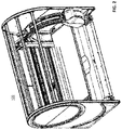
- FIG. 2 is another perspective three-dimensional view of the foreign object scanner of the present invention.
- FIG. 3 is a side view of the foreign object scanner of the present invention.
- FIG. 4 is a different side view of the foreign object scanner of the present invention.
- FIG. 5 is a top view of the foreign object scanner of the present invention.
- FIG. 6 is a perspective three-dimensional view of the foreign object scanner of the present invention with the table out.
- FIG. 7 is another perspective three-dimensional view of the foreign object scanner of the present invention with the table out.
- FIG. 8 is a system block diagram of the system.
- FIG. 9 is a view looking horizontally towards the head of the body
- FIG. 10 is a different side view of C-frame (C-arm).
- FIGS. 11A-11B is a perspective three-dimensional view of C-frame.
- FIGS. 12A-12B show additional views of the C-frame and the detector arrays.
- FIG. 13 is a positioning precision of the electromagnetic drive.
- FIG. 14 is a layout of detector boards on the C-frame.
- FIG. 15 - FIG. 20 show perspective views of a variation of the design with sliding doors.
- FIG. 21 - FIG. 23 show perspective views of a variation of the design in a lightweight version.
- a set of detector arrays 1002 are located on the C-frame 102 (see FIG. 6 ) (which is itself mounted on a gantry 104 , see FIG. 1 ), at the same radius from a focal point of the X-ray source.
- the radius is 1237.6 mm, although, obviously, the particular radius depends on engineering design considerations.
- the active length of each detector array is 153.6 mm and the active width of each detector array is 6.4 mm
- Each detector array has 64 pixel lines and the size of each pixel is 0.1 ⁇ 0.1 mm. A total of 7 detector arrays are used in this example.
- the radius line is perpendicular to the center of each detector array 1002 (see FIG. 14 ).
- the width of the table 106 (see FIG. 1 ) that is transparent to the X-rays is 830 mm, in the exemplary embodiment.
- Such an arrangement of the detector arrays 1002 permits to (1) considerably increase the width of the transparent portion of the table 106 (i.e., the width of the object/body being scanned), while keeping the overall dimensions of the scanner to a minimum; and (2) to generate an image of the object with minimal geometric distortions, which, in turn, permits to (3) use algorithms for generating a high-contrast image.
- the scanner system includes the following components (see system block diagram in FIG. 8 ):
- the rotating mechanism, C-frame, detector and radiation system form a production unit of the system.
- the use of the selected parameters of the X-ray generator and the detector arrays permit (1) a continuous imaging process that does not require interruptions for cooling of the X-ray source, (2) using TDS technology.
- the image is processed using a computer, where it is possible to adjust multi-threaded distributed computing using capabilities of a multi-core processor.
- a 2D digital image is formed so that the number of elements (pixels) along one coordinate (in the scanning direction) is determined by the number of scanning steps (number of counting) and the number of detectors in the direction perpendicular to the scanning direction along the other coordinate.
- a personal computer with a processor INTEL CORE i7-8700 or better may be used for high speed data processing from the detector and image generation.
- the detector receives X-rays and generates images in TDS (Time Delayed Summation) mode. This is when an object moves across the detector in such a way the same area is imaged by each row of the detector at a time allowing each row to be summed to get a more statistically accurate sample of that section of the object. These samples form lines in the output image and so form a complete scan of the object.
- TDS Time Delayed Summation
- detector pixel values are shifted along rows during image acquisition to compensate for detector motion.
- This detector is a non-scintillating detector type (e.g., cadmium-telluride) to directly count the photons.
- This detector allows to generate good quality X-Ray image using relatively low-current X-ray sources, e.g., up to 2.5 mA current requirements for the X-ray source. Compare this with conventional scanners that use scintillator-type detectors, and require a source that has a max current of 400 mA—which means it can only work in this regime only 13-15 sec, and then requires to be off-line for cooling. This, in turn, forces the source to move at high speed, relative to the object being scanned. The present scanner does not need such high speed because doesn't need cooling after each scanning (in the exemplary embodiment, the scanner has an X-ray source with max. current of 2.5 mA, 200 kV, focal spot 0.8 mm, fan angle of 49.7°, see FIG. 14 , in one example).
- the use of an electromagnetic drive permits high-precision in positioning of the C-frame (and of the detector arrays), while the movement of the C-frame is relatively smooth in the lateral direction (the amplitude of the vibrations is less than 50 microns, which again assists in generating a high-quality high-contrast image).
- the electromagnetic drive is a linear synchronous motor that includes a moving element (anchor) and a magnetic strip (stator).
- the anchor has a magnetic geared drive that fits into the windings, which is sealed with a thermally conductive compound.
- the stator includes rare earth magnets of alternating polarity. A typical gap between the anchor and the stator is about 1 mm
- High positioning precision (see FIG. 13 , where positioning precision is about 7 microns) is enabled by the fact that no mechanical coupling is needed—this permits high precision of the motor, high reliability, highly stable electromotive force, accurate and high acceleration, and very precise movement and positioning.
- a body up to 250 kg can be placed on the table and scanned (see FIG. 9 , showing a view looking horizontally towards the head of the body, exemplary dimensions listed in mm).
- a larger scanning area (830 ⁇ 2100 mm) is also possible with the proposed arrangement, compared to conventional solutions.
- the basic design of the scanner 100 shown in ( FIG. 1 - FIG. 5 ), can have various variants of the design while retaining its basic structural functionality, which allows to obtain high-contrast high-quality images.
- the basic design can be modified in the X-ray protective design with sliding doors 1502 (see various perspective views shown in FIG. 15 - FIG. 20 ), which allows to use the scanner without a special X-ray protective room.
- the basic structure can be modified in the lightweight version ( FIG. 21 - FIG. 23 ), which allows to reduce its overall weight, dimensions and provide the visibility of the table with the patient and the scanning process from three sides. while maintaining the specified rigidity of the structure
- the direct photon counting detector can operate in a dual-energy mode.
- the advantage of using two energies in comparison with one is the ability to recognize different materials by atomic number (Z), which is achieved by comparing the degree of attenuation of x-rays for different energies, depending on the atomic number of the material.
- the estimate is based on the ratio between the low-energy (SE1) and high-energy (SE2) signals from the detector.
- the proposed scanner for human bodies can be used for estimate the density of human bodies bones. That allows to diagnose osteoporosis before a broken bone occurs. This test helps to estimate the density of the bones and reduce the chance of breaking a bone.
Abstract
Description
-
- fast heating of the x-ray tube, which limits the scanning time to 13-15 seconds;
- a long period of time of inactivity between the scan to cool the x-ray tube;
- the low period of the lifetime of the x-ray tube and the high cost of replacing it.
-
- The stand includes:
-
Frame 110; - Linear drive;
-
- Rotating mechanism;
- C-
frame 102; - Detector (see
elements 1002 inFIGS. 10 and 14 ); - Radiation system composed of:
- X-Ray generator 902 (see
FIG. 9 ); - Collimator;
- X-Ray generator 902 (see
- Position control system;
- Lifting table;
- Electrical cabinet;
- Electric equipment;
- Casings;
- Operator's AWS composed of:
- Remote control;
- Acquisition workstation.
- The stand includes:
Claims (19)
Priority Applications (1)
| Application Number | Priority Date | Filing Date | Title |
|---|---|---|---|
| US16/531,339 US11375962B2 (en) | 2019-08-05 | 2019-08-05 | Fast foreign object scanner for scanning human bodies |
Applications Claiming Priority (1)
| Application Number | Priority Date | Filing Date | Title |
|---|---|---|---|
| US16/531,339 US11375962B2 (en) | 2019-08-05 | 2019-08-05 | Fast foreign object scanner for scanning human bodies |
Publications (2)
| Publication Number | Publication Date |
|---|---|
| US20210038175A1 US20210038175A1 (en) | 2021-02-11 |
| US11375962B2 true US11375962B2 (en) | 2022-07-05 |
Family
ID=74499599
Family Applications (1)
| Application Number | Title | Priority Date | Filing Date |
|---|---|---|---|
| US16/531,339 Active 2039-08-13 US11375962B2 (en) | 2019-08-05 | 2019-08-05 | Fast foreign object scanner for scanning human bodies |
Country Status (1)
| Country | Link |
|---|---|
| US (1) | US11375962B2 (en) |
Families Citing this family (1)
| Publication number | Priority date | Publication date | Assignee | Title |
|---|---|---|---|---|
| US11726220B2 (en) * | 2021-01-19 | 2023-08-15 | Analogic Corporation | Radiation detectors for scanning systems, and related scanning systems |
Citations (61)
| Publication number | Priority date | Publication date | Assignee | Title |
|---|---|---|---|---|
| US3784820A (en) * | 1970-06-22 | 1974-01-08 | Univ Case Western Reserve | Tomographic scanning process |
| US4230129A (en) * | 1975-07-11 | 1980-10-28 | Leveen Harry H | Radio frequency, electromagnetic radiation device having orbital mount |
| US5287546A (en) * | 1992-09-14 | 1994-02-15 | Lunar Corporation | Patient positioning apparatus for bone scanning |
| US5464984A (en) * | 1985-12-11 | 1995-11-07 | General Imaging Corporation | X-ray imaging system and solid state detector therefor |
| US5509042A (en) * | 1991-02-13 | 1996-04-16 | Lunar Corporation | Automated determination and analysis of bone morphology |
| US5657369A (en) * | 1993-11-22 | 1997-08-12 | Hologic, Inc. | X-ray bone densitometry system having forearm positioning assembly |
| US5715820A (en) * | 1995-06-06 | 1998-02-10 | Hologic, Inc. | X-ray bone densitometry using multiple pass scanning with image blending |
| US5745544A (en) * | 1991-02-13 | 1998-04-28 | Lunar Corporation | Bone densitometer with film cassette |
| US5748705A (en) * | 1993-11-22 | 1998-05-05 | Hologic Inc. | X-ray bone densitometry |
| US6147352A (en) * | 1998-02-23 | 2000-11-14 | Digirad Corporation | Low profile open ring single photon emission computed tomographic imager |
| US6217214B1 (en) * | 1993-11-22 | 2001-04-17 | Hologic, Inc. | X-ray bone densitometry apparatus |
| US6256374B1 (en) * | 1998-10-19 | 2001-07-03 | Fluoroscan Imaging Systems, Inc. | Miniature C-arm apparatus with dual video display monitor and single driver interface therefor |
| US20010048732A1 (en) * | 2000-02-09 | 2001-12-06 | Wilson Kevin E. | Two-dimensional slot x-ray bone densitometry, radiography and tomography |
| US20020018542A1 (en) * | 1998-11-30 | 2002-02-14 | Gerhard Fenkart | Nonintrusive inspection system |
| US6438201B1 (en) * | 1994-11-23 | 2002-08-20 | Lunar Corporation | Scanning densitometry system with adjustable X-ray tube current |
| US20040022350A1 (en) * | 2002-02-15 | 2004-02-05 | Breakaway Imaging, Llc | Breakable gantry apparatus for multidimensional x-ray based imaging |
| US20050117700A1 (en) * | 2003-08-08 | 2005-06-02 | Peschmann Kristian R. | Methods and systems for the rapid detection of concealed objects |
| US20050234327A1 (en) * | 2004-04-06 | 2005-10-20 | Saracen Michael J | Robotic arm for patient positioning assembly |
| US20060291623A1 (en) * | 2005-06-14 | 2006-12-28 | L-3 Communications Security And Detection Systems, Inc. | Inspection system with material identification |
| US20070085011A1 (en) * | 2005-09-09 | 2007-04-19 | Dieter Ritter | Method and imaging system for generation of a scintigraphic exposure of a patient |
| US20080082002A1 (en) * | 2006-10-02 | 2008-04-03 | Kevin Wilson | Assessing cardiovascular and vertebral/hip fracture risk and bone condition using quantitative computed tomography and/or dual energy x-ray absorptiometry |
| US20090086907A1 (en) * | 2007-06-09 | 2009-04-02 | Steven Winn Smith | Automobile Scanning System |
| US20090147925A1 (en) * | 2005-04-13 | 2009-06-11 | Lodox Systems (Proprietary) Limited | Calibration tool and a method of calibrating an imaging system |
| US20090296880A1 (en) * | 2008-05-30 | 2009-12-03 | Lodox Systems ( Proprietary ) Limited | Distortion correction method for linear scanning x-ray system |
| US7903779B2 (en) * | 2002-08-21 | 2011-03-08 | Medtronic Navigation, Inc. | Apparatus and method for reconstruction of volumetric images in a divergent scanning computed tomography system |
| US20110058649A1 (en) * | 2009-09-10 | 2011-03-10 | General Electric Company | Transverse scanning bone densitometer and detector used in same |
| US20110085640A1 (en) * | 2009-10-12 | 2011-04-14 | Franz Fadler | Radiation therapy device |
| US20110122990A1 (en) * | 2009-11-24 | 2011-05-26 | Ehud Dafni | Methods apparatus assemblies and systems for implementing a ct scanner |
| US20110182402A1 (en) * | 2010-01-28 | 2011-07-28 | Varian Medical Systems, Inc. | Imaging breast cancerous lesions with microcalcifications |
| US20110280379A1 (en) * | 2010-05-14 | 2011-11-17 | Michael Maschke | Imaging apparatus comprising a ring-shaped gantry |
| US20120014503A1 (en) * | 2010-07-14 | 2012-01-19 | Christer Ullberg | Computed Tomography Scanning System and Method |
| US20120087465A1 (en) * | 2010-10-11 | 2012-04-12 | Abdelaziz Ikhlef | Multi-faceted tileable detector for volumetric computed tomography imaging |
| US20120232375A1 (en) * | 2009-09-11 | 2012-09-13 | StraxCorp Pty Ltd. | Method and system for image analysis of selected tissue structures |
| US20130039472A1 (en) * | 2011-02-08 | 2013-02-14 | Rapican Systems, Inc. | Covert surveillance using multi-modality sensing |
| US8424133B1 (en) * | 2011-02-18 | 2013-04-23 | Remo J. Rossi | Iso-roll table |
| US20130235971A1 (en) * | 2012-02-22 | 2013-09-12 | L-3 Communications Security and Detection Systems Corp. | X-ray imager with sparse detector array |
| US20130343519A1 (en) * | 2012-06-25 | 2013-12-26 | George W. Ma | Portable dual-energy radiographic x-ray perihpheral bone density and imaging systems and methods |
| US20140171725A1 (en) * | 2012-09-05 | 2014-06-19 | Varian Medical Systems, Inc. | Radiation systems with minimal or no shielding requirement on building |
| US20140211925A1 (en) * | 2013-01-31 | 2014-07-31 | Ge Medical Systems Global Technology Company, Llc | Geometry calibration algorithm for large flat module detector ct scanner |
| US20140226789A1 (en) * | 2011-02-08 | 2014-08-14 | Joseph Bendahan | Covert Surveillance Using Multi-Modality Sensing |
| US20150146853A1 (en) * | 2005-05-02 | 2015-05-28 | Oy Ajat Ltd. | Radiation imaging device with irregular rectangular shape and extraoral dental imaging system therefrom |
| US20150246244A1 (en) * | 2014-02-28 | 2015-09-03 | Decision Sciences International Corporation | Charged particle tomography scanner for real-time volumetric radiation dose monitoring and control |
| US20150366519A1 (en) * | 2013-01-31 | 2015-12-24 | Shimadzu Corporation | Positron ct apparatus |
| US20160203598A1 (en) * | 2013-08-21 | 2016-07-14 | Shimadzu Corporation | Image processing device |
| US20170053414A1 (en) * | 2015-08-20 | 2017-02-23 | Siemens Healthcare Gmbh | Method for local improvement of image quality |
| US20170245826A1 (en) * | 2016-02-29 | 2017-08-31 | Toshiba Medical Systems Corporation | X-ray diagnostic apparatus |
| US20170258425A1 (en) * | 2016-03-09 | 2017-09-14 | Medtronic Navigation, Inc. | Transformable Imaging System |
| US20170293039A1 (en) * | 2016-04-06 | 2017-10-12 | Siemens Healthcare Gmbh | X-ray detector with protective element and adhesive element |
| US20170340268A1 (en) * | 2016-05-30 | 2017-11-30 | Prismatic Sensors Ab | X-ray imaging for enabling assessment of scoliosis |
| US20180192967A1 (en) * | 2015-06-15 | 2018-07-12 | Koninklijke Philips N.V. | Tiled detector arrangement for differential phase contrast ct |
| US20180240842A1 (en) * | 2015-08-31 | 2018-08-23 | G-Ray Switzerland Sa | Photon counting cone-beam ct apparatus with monolithic cmos integrated pixel detectors |
| US20180289339A1 (en) * | 2015-12-04 | 2018-10-11 | Epica International, Inc. | Radiological imaging device |
| US20180304098A1 (en) * | 2017-04-21 | 2018-10-25 | Varian Medical Systems, Inc. | Dual-axis ring gantry radiotherapy systems |
| US20180356352A1 (en) * | 2015-06-16 | 2018-12-13 | Dylog Italia S.P.A. | Non-Destructive X-ray Inspection Machine, Devices Provided for Such Machine and Method for Operating the Same |
| US20190179040A1 (en) * | 2017-12-08 | 2019-06-13 | X-Scan Imaging Corporation | Integrated multi-slice x-ray detector for in-line computed tomography |
| US20190223278A1 (en) * | 2018-01-12 | 2019-07-18 | Accuray Incorporated | Detecting motion by using a low dose x-ray image |
| US20190388044A1 (en) * | 2018-06-25 | 2019-12-26 | Shimadzu Corporation | Radiation fluoroscopic imaging apparatus |
| US20200029927A1 (en) * | 2017-03-31 | 2020-01-30 | Hologic, Inc. | Multiple modality body composition analysis |
| US20200060638A1 (en) * | 2016-11-02 | 2020-02-27 | Eurotec Medical Systems S.R.L. | Apparatus for x-ray bone densitometry |
| US20200163643A1 (en) * | 2017-07-04 | 2020-05-28 | Eos Imaging | Method of radiography of an organ of a patient |
| US20200205763A1 (en) * | 2018-12-27 | 2020-07-02 | Medtronic Navigation, Inc. | System and Method for Imaging a Subject |
-
2019
- 2019-08-05 US US16/531,339 patent/US11375962B2/en active Active
Patent Citations (62)
| Publication number | Priority date | Publication date | Assignee | Title |
|---|---|---|---|---|
| US3784820A (en) * | 1970-06-22 | 1974-01-08 | Univ Case Western Reserve | Tomographic scanning process |
| US4230129A (en) * | 1975-07-11 | 1980-10-28 | Leveen Harry H | Radio frequency, electromagnetic radiation device having orbital mount |
| US5464984A (en) * | 1985-12-11 | 1995-11-07 | General Imaging Corporation | X-ray imaging system and solid state detector therefor |
| US5509042A (en) * | 1991-02-13 | 1996-04-16 | Lunar Corporation | Automated determination and analysis of bone morphology |
| US5745544A (en) * | 1991-02-13 | 1998-04-28 | Lunar Corporation | Bone densitometer with film cassette |
| US5287546A (en) * | 1992-09-14 | 1994-02-15 | Lunar Corporation | Patient positioning apparatus for bone scanning |
| US6217214B1 (en) * | 1993-11-22 | 2001-04-17 | Hologic, Inc. | X-ray bone densitometry apparatus |
| US5748705A (en) * | 1993-11-22 | 1998-05-05 | Hologic Inc. | X-ray bone densitometry |
| US5657369A (en) * | 1993-11-22 | 1997-08-12 | Hologic, Inc. | X-ray bone densitometry system having forearm positioning assembly |
| US6438201B1 (en) * | 1994-11-23 | 2002-08-20 | Lunar Corporation | Scanning densitometry system with adjustable X-ray tube current |
| US5715820A (en) * | 1995-06-06 | 1998-02-10 | Hologic, Inc. | X-ray bone densitometry using multiple pass scanning with image blending |
| US6147352A (en) * | 1998-02-23 | 2000-11-14 | Digirad Corporation | Low profile open ring single photon emission computed tomographic imager |
| US6256374B1 (en) * | 1998-10-19 | 2001-07-03 | Fluoroscan Imaging Systems, Inc. | Miniature C-arm apparatus with dual video display monitor and single driver interface therefor |
| US20020018542A1 (en) * | 1998-11-30 | 2002-02-14 | Gerhard Fenkart | Nonintrusive inspection system |
| US20010048732A1 (en) * | 2000-02-09 | 2001-12-06 | Wilson Kevin E. | Two-dimensional slot x-ray bone densitometry, radiography and tomography |
| US20040022350A1 (en) * | 2002-02-15 | 2004-02-05 | Breakaway Imaging, Llc | Breakable gantry apparatus for multidimensional x-ray based imaging |
| US6940941B2 (en) * | 2002-02-15 | 2005-09-06 | Breakaway Imaging, Llc | Breakable gantry apparatus for multidimensional x-ray based imaging |
| US7903779B2 (en) * | 2002-08-21 | 2011-03-08 | Medtronic Navigation, Inc. | Apparatus and method for reconstruction of volumetric images in a divergent scanning computed tomography system |
| US20050117700A1 (en) * | 2003-08-08 | 2005-06-02 | Peschmann Kristian R. | Methods and systems for the rapid detection of concealed objects |
| US20050234327A1 (en) * | 2004-04-06 | 2005-10-20 | Saracen Michael J | Robotic arm for patient positioning assembly |
| US20090147925A1 (en) * | 2005-04-13 | 2009-06-11 | Lodox Systems (Proprietary) Limited | Calibration tool and a method of calibrating an imaging system |
| US20150146853A1 (en) * | 2005-05-02 | 2015-05-28 | Oy Ajat Ltd. | Radiation imaging device with irregular rectangular shape and extraoral dental imaging system therefrom |
| US20060291623A1 (en) * | 2005-06-14 | 2006-12-28 | L-3 Communications Security And Detection Systems, Inc. | Inspection system with material identification |
| US20070085011A1 (en) * | 2005-09-09 | 2007-04-19 | Dieter Ritter | Method and imaging system for generation of a scintigraphic exposure of a patient |
| US20080082002A1 (en) * | 2006-10-02 | 2008-04-03 | Kevin Wilson | Assessing cardiovascular and vertebral/hip fracture risk and bone condition using quantitative computed tomography and/or dual energy x-ray absorptiometry |
| US20090086907A1 (en) * | 2007-06-09 | 2009-04-02 | Steven Winn Smith | Automobile Scanning System |
| US20090296880A1 (en) * | 2008-05-30 | 2009-12-03 | Lodox Systems ( Proprietary ) Limited | Distortion correction method for linear scanning x-ray system |
| US20110058649A1 (en) * | 2009-09-10 | 2011-03-10 | General Electric Company | Transverse scanning bone densitometer and detector used in same |
| US20120232375A1 (en) * | 2009-09-11 | 2012-09-13 | StraxCorp Pty Ltd. | Method and system for image analysis of selected tissue structures |
| US20110085640A1 (en) * | 2009-10-12 | 2011-04-14 | Franz Fadler | Radiation therapy device |
| US20110122990A1 (en) * | 2009-11-24 | 2011-05-26 | Ehud Dafni | Methods apparatus assemblies and systems for implementing a ct scanner |
| US20110182402A1 (en) * | 2010-01-28 | 2011-07-28 | Varian Medical Systems, Inc. | Imaging breast cancerous lesions with microcalcifications |
| US20110280379A1 (en) * | 2010-05-14 | 2011-11-17 | Michael Maschke | Imaging apparatus comprising a ring-shaped gantry |
| US20120014503A1 (en) * | 2010-07-14 | 2012-01-19 | Christer Ullberg | Computed Tomography Scanning System and Method |
| US20120087465A1 (en) * | 2010-10-11 | 2012-04-12 | Abdelaziz Ikhlef | Multi-faceted tileable detector for volumetric computed tomography imaging |
| US20130039472A1 (en) * | 2011-02-08 | 2013-02-14 | Rapican Systems, Inc. | Covert surveillance using multi-modality sensing |
| US20140226789A1 (en) * | 2011-02-08 | 2014-08-14 | Joseph Bendahan | Covert Surveillance Using Multi-Modality Sensing |
| US8424133B1 (en) * | 2011-02-18 | 2013-04-23 | Remo J. Rossi | Iso-roll table |
| US20130235971A1 (en) * | 2012-02-22 | 2013-09-12 | L-3 Communications Security and Detection Systems Corp. | X-ray imager with sparse detector array |
| US20130343519A1 (en) * | 2012-06-25 | 2013-12-26 | George W. Ma | Portable dual-energy radiographic x-ray perihpheral bone density and imaging systems and methods |
| US20140171725A1 (en) * | 2012-09-05 | 2014-06-19 | Varian Medical Systems, Inc. | Radiation systems with minimal or no shielding requirement on building |
| US20140211925A1 (en) * | 2013-01-31 | 2014-07-31 | Ge Medical Systems Global Technology Company, Llc | Geometry calibration algorithm for large flat module detector ct scanner |
| US20150366519A1 (en) * | 2013-01-31 | 2015-12-24 | Shimadzu Corporation | Positron ct apparatus |
| US20160203598A1 (en) * | 2013-08-21 | 2016-07-14 | Shimadzu Corporation | Image processing device |
| US20150246244A1 (en) * | 2014-02-28 | 2015-09-03 | Decision Sciences International Corporation | Charged particle tomography scanner for real-time volumetric radiation dose monitoring and control |
| US20180192967A1 (en) * | 2015-06-15 | 2018-07-12 | Koninklijke Philips N.V. | Tiled detector arrangement for differential phase contrast ct |
| US20180356352A1 (en) * | 2015-06-16 | 2018-12-13 | Dylog Italia S.P.A. | Non-Destructive X-ray Inspection Machine, Devices Provided for Such Machine and Method for Operating the Same |
| US20170053414A1 (en) * | 2015-08-20 | 2017-02-23 | Siemens Healthcare Gmbh | Method for local improvement of image quality |
| US20180240842A1 (en) * | 2015-08-31 | 2018-08-23 | G-Ray Switzerland Sa | Photon counting cone-beam ct apparatus with monolithic cmos integrated pixel detectors |
| US20180289339A1 (en) * | 2015-12-04 | 2018-10-11 | Epica International, Inc. | Radiological imaging device |
| US20170245826A1 (en) * | 2016-02-29 | 2017-08-31 | Toshiba Medical Systems Corporation | X-ray diagnostic apparatus |
| US20170258425A1 (en) * | 2016-03-09 | 2017-09-14 | Medtronic Navigation, Inc. | Transformable Imaging System |
| US20170293039A1 (en) * | 2016-04-06 | 2017-10-12 | Siemens Healthcare Gmbh | X-ray detector with protective element and adhesive element |
| US20170340268A1 (en) * | 2016-05-30 | 2017-11-30 | Prismatic Sensors Ab | X-ray imaging for enabling assessment of scoliosis |
| US20200060638A1 (en) * | 2016-11-02 | 2020-02-27 | Eurotec Medical Systems S.R.L. | Apparatus for x-ray bone densitometry |
| US20200029927A1 (en) * | 2017-03-31 | 2020-01-30 | Hologic, Inc. | Multiple modality body composition analysis |
| US20180304098A1 (en) * | 2017-04-21 | 2018-10-25 | Varian Medical Systems, Inc. | Dual-axis ring gantry radiotherapy systems |
| US20200163643A1 (en) * | 2017-07-04 | 2020-05-28 | Eos Imaging | Method of radiography of an organ of a patient |
| US20190179040A1 (en) * | 2017-12-08 | 2019-06-13 | X-Scan Imaging Corporation | Integrated multi-slice x-ray detector for in-line computed tomography |
| US20190223278A1 (en) * | 2018-01-12 | 2019-07-18 | Accuray Incorporated | Detecting motion by using a low dose x-ray image |
| US20190388044A1 (en) * | 2018-06-25 | 2019-12-26 | Shimadzu Corporation | Radiation fluoroscopic imaging apparatus |
| US20200205763A1 (en) * | 2018-12-27 | 2020-07-02 | Medtronic Navigation, Inc. | System and Method for Imaging a Subject |
Also Published As
| Publication number | Publication date |
|---|---|
| US20210038175A1 (en) | 2021-02-11 |
Similar Documents
| Publication | Publication Date | Title |
|---|---|---|
| US7796734B2 (en) | Multiple image collection and synthesis for personnel screening | |
| JP3168824B2 (en) | X-ray CT system | |
| EP2223165B1 (en) | Multiple image collection and synthesis for personnel screening | |
| CN1643371A (en) | Systems and methods for imaging large field-of-view objects | |
| JPH1151879A (en) | Non-destructive inspection device | |
| CN114199907B (en) | Multi-resolution CT imaging system and method | |
| AU2015415888B2 (en) | An electron guiding and receiving element | |
| US20230255584A1 (en) | Fast 3D Radiography with Multiple Pulsed X-ray Sources by Deflecting Tube Electron Beam using Electro-Magnetic Field | |
| US11375962B2 (en) | Fast foreign object scanner for scanning human bodies | |
| JP6877975B2 (en) | X-ray CT device | |
| US10492746B2 (en) | Spherical detector for CT system | |
| JP2000046760A (en) | X-ray tomographic surface inspection apparatus | |
| EP3686913A1 (en) | Anode target, ray light source, computed tomography device, and imaging method | |
| JP2004337609A (en) | Collimator assembly for computer tomography system | |
| EP1463085B1 (en) | X-ray inspection system and method of operating | |
| US5293416A (en) | Radiography apparatus for producing X-ray shadowgraphs | |
| US11226296B2 (en) | Tunnel computerised tomographic scanner and method for acquiring images from a scintillator of a tunnel computerised tomography scanner | |
| US11762123B2 (en) | X-ray cross technology for human body inspection | |
| NL8005171A (en) | SCANNER FOR A COMPUTER-CONTROLLED TOMOGRAPHIC SYSTEM. | |
| JPH01254148A (en) | X-ray ct scanner | |
| US20240122568A1 (en) | Fast 3D Radiography with Multiple Pulsed X-ray Sources by Deflecting Tube Electron Beam using Electro-Magnetic Field | |
| CN114732426B (en) | Three-dimensional ultrafast X-ray CT imaging system and imaging method | |
| JP2006029886A (en) | Stereographic image acquisition method, and device therefor | |
| WO2023056881A1 (en) | Ct imaging system | |
| Cañas et al. | Large area detector with the Medipix2 chip |
Legal Events
| Date | Code | Title | Description |
|---|---|---|---|
| AS | Assignment |
Owner name: ADANI SYSTEMS, INC., VIRGINIA Free format text: ASSIGNMENT OF ASSIGNORS INTEREST;ASSIGNOR:LINEV, VLADIMIR N.;REEL/FRAME:049956/0279 Effective date: 20190805 |
|
| FEPP | Fee payment procedure |
Free format text: ENTITY STATUS SET TO UNDISCOUNTED (ORIGINAL EVENT CODE: BIG.); ENTITY STATUS OF PATENT OWNER: SMALL ENTITY |
|
| FEPP | Fee payment procedure |
Free format text: ENTITY STATUS SET TO SMALL (ORIGINAL EVENT CODE: SMAL); ENTITY STATUS OF PATENT OWNER: SMALL ENTITY |
|
| STPP | Information on status: patent application and granting procedure in general |
Free format text: NON FINAL ACTION MAILED |
|
| STPP | Information on status: patent application and granting procedure in general |
Free format text: RESPONSE TO NON-FINAL OFFICE ACTION ENTERED AND FORWARDED TO EXAMINER |
|
| STPP | Information on status: patent application and granting procedure in general |
Free format text: FINAL REJECTION MAILED |
|
| STPP | Information on status: patent application and granting procedure in general |
Free format text: RESPONSE AFTER FINAL ACTION FORWARDED TO EXAMINER |
|
| STPP | Information on status: patent application and granting procedure in general |
Free format text: ADVISORY ACTION MAILED |
|
| STPP | Information on status: patent application and granting procedure in general |
Free format text: DOCKETED NEW CASE - READY FOR EXAMINATION |
|
| STPP | Information on status: patent application and granting procedure in general |
Free format text: NON FINAL ACTION MAILED |
|
| STPP | Information on status: patent application and granting procedure in general |
Free format text: RESPONSE TO NON-FINAL OFFICE ACTION ENTERED AND FORWARDED TO EXAMINER |
|
| STPP | Information on status: patent application and granting procedure in general |
Free format text: FINAL REJECTION MAILED |
|
| STPP | Information on status: patent application and granting procedure in general |
Free format text: RESPONSE AFTER FINAL ACTION FORWARDED TO EXAMINER |
|
| AS | Assignment |
Owner name: LINEV SYSTEMS, INC., VIRGINIA Free format text: ASSIGNMENT OF ASSIGNORS INTEREST;ASSIGNOR:ADANI SYSTEMS, INC.;REEL/FRAME:059877/0690 Effective date: 20220510 |
|
| STPP | Information on status: patent application and granting procedure in general |
Free format text: PUBLICATIONS -- ISSUE FEE PAYMENT RECEIVED |
|
| STPP | Information on status: patent application and granting procedure in general |
Free format text: PUBLICATIONS -- ISSUE FEE PAYMENT VERIFIED |
|
| STCF | Information on status: patent grant |
Free format text: PATENTED CASE |
|
| AS | Assignment |
Owner name: LINEV SYSTEMS US, INC., VIRGINIA Free format text: CORRECTIVE ASSIGNMENT TO CORRECT THE NAME OF ASSIGNEE PREVIOUSLY RECORDED AT REEL: 059877 FRAME: 0690. ASSIGNOR(S) HEREBY CONFIRMS THE ASSIGNMENT;ASSIGNOR:LINEV SYSTEMS, INC.;REEL/FRAME:060403/0227 Effective date: 20220620 |