EP2952648A1 - Clamping arrangement for a plate-shaped body - Google Patents
Clamping arrangement for a plate-shaped body Download PDFInfo
- Publication number
- EP2952648A1 EP2952648A1 EP15169639.0A EP15169639A EP2952648A1 EP 2952648 A1 EP2952648 A1 EP 2952648A1 EP 15169639 A EP15169639 A EP 15169639A EP 2952648 A1 EP2952648 A1 EP 2952648A1
- Authority
- EP
- European Patent Office
- Prior art keywords
- clamping
- arrangement according
- plate
- clamping arrangement
- shaped body
- Prior art date
- Legal status (The legal status is an assumption and is not a legal conclusion. Google has not performed a legal analysis and makes no representation as to the accuracy of the status listed.)
- Granted
Links
Images
Classifications
-
- E—FIXED CONSTRUCTIONS
- E04—BUILDING
- E04F—FINISHING WORK ON BUILDINGS, e.g. STAIRS, FLOORS
- E04F11/00—Stairways, ramps, or like structures; Balustrades; Handrails
- E04F11/18—Balustrades; Handrails
- E04F11/181—Balustrades
- E04F11/1851—Filling panels, e.g. concrete, sheet metal panels
- E04F11/1853—Glass panels
Definitions
- This present invention concerns a clamping arrangement for clamping a plate-shaped body, for example, a glass plate.
- the object of this invention is to provide an improved adjustable, but still solid clamping arrangement for plate-shaped bodies.
- clamping arrangement in accordance with the invention, is characterised in that it comprises:
- clamping arrangement according to the invention is that for the benefit of good stability of the clamping arrangement, it is assumed that the profile parts are inseparable from each other and connected to the profile of the clamping arrangement, and, in this way intrinsically solid, which border the opening in which the plate-shaped body is located.
- the body is fixed in the opening while it is located therein between the pressure elements on opposite sides which support the fixed profile parts. Setting the clamping force, and also of the often vertical position or angle of the solid clamped plate-shaped body takes place by means of at least one clamping organ applied in or onto both profile parts.
- one or more of the clamping organs are constructed as clamping organs which produce an adjustable clamping force.
- the clamping organs are constructed as adjustable clamping organs, but the clamping organs may also be constructed as fixed organs.
- an inclined clamping surface is mentioned here, which supports or forms an integral part of one or both profile parts.
- one wedge-shaped constructed part of the pressure element which operates at the bottom of the opening makes frictional contact with the inclined clamp surface, as a result of which the plate-shaped body is clamped in fixed position.
- a further embodiment of the clamping arrangement is characterised in that at least the pressure element not equipped with clamping organs has a side facing its pressure element which side exhibits a convexity.
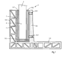
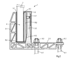
- Figures 1 and 2 each show a clamping arrangement 1 which is suitable for clamping a plate-shaped body 2.
- the plate-shaped body 2 may be a glass, metal, or plastic plate.
- a glass plate it can be considered, as being or not being composed of multiple layers, possibly toughened glass, including, among other things, such as used in a fence or railing along hand rails, balconies, stairs, etc.
- reduced back-lash clamping of the plate-shaped body 2 is of great importance.
- a small clearance at the clamping side, usually the bottom, of the body 2 already leads to a swing which is observable and experienced by users to be unsafe, or greater clearance on its opposite, upper, unclamped side.
- the plate-shaped body 2 comprises a profile 3 which is constructed from profile parts which are inseparable from each other 3-1, 3-2 having there between an opening 4 for introducing the plate-shaped body 2 therein.
- the clamping arrangement 1 comprises two supporting pressure elements 5-1, 5-2, each on opposite sides of the introduced plate-shaped body 2, against the profile parts 3-1, 3-2 in the opening 4.
- At least one of the two profile parts 3-1, 3-2 is equipped with one or more clamping organs, a clamping force on the pressure elements concerned 5-1, 5-2, and thus exercised on the plate-shaped body 2, to be further explained hereinafter as clamping organs 6-1, 6-2, 6-3; also referred to as 6.
- the pressure elements 5-1, 5-2 are flat, somewhat flexible elements which are at least applied on opposite sides of the plate-shaped body 2 in the opening 4.
- clamp force exerted by the various clamping organs 6 on the body 2 is spread over a larger area of the part of the body 2, which is located in the opening 4.
- the lower, or short side of the clamped part of the body 2 is supported by a supporting part 5-3, whereby the pressure part concerned, in this case 5-1, is L-shaped.
- the supporting part 5-3 can form a whole with the pressure element 5-1.
- Figure 1 shows a construction of the clamping arrangement 1 in which only the profile parts 3-2 are equipped with two clamping members 6-1, 6-2, and in this case, placed above each other, each of which is constructed as a pressure clamping screw against the pressure element 5-2.
- the clamping screws concerned can, for this purpose, be turned from the inside, i.e. as seen from the right in the figure, in the threaded openings in the element 5-2 in order to exert an adjustable clamping force on the plate-shaped body 2. This is particularly important when the clamping arrangement is applied at the edge of a patio or balcony, the outer side of which, in particular, after the application of the plate-shaped body 2 is not easily accessible or is not accessible without tools.
- Figure 2 shows a construction of the clamping arrangement 1 in which the side facing the pressure elements 5-2 of the clamping organs 6-1, 6-3 3-2, profile part 3-2 is equipped with clamping organ 6-3 constructed as inclined clamping surface.
- a projecting wedge-shaped part of the pressure element 5-2 at the bottom of opening 4 makes frictional contact with the inclined clamp surface by striking that pressure element 5-2 the foot at the bottom in opening 4 of the body 4 is moved to the left in Figure 2 and it is also clamped more firmly.
- the clamping organ 6-1 which is equipped with a clamping screw is located above the inclined clamping surface of the profile part 3-2, therewith the position of the plate-shaped body 2 can be further adjusted.
- the convexity 7 can be introduced in the side facing pressure element 5-1 of the profile part 3-1 which is not equipped with clamping organs.
- the profile 3 has a continuous ground profile 3-3 beyond the profile part 3-2 in which openings have been introduced in order to fix therein or thereto, respectively, adjustment bolts 8-1, or locknuts 8-2, respectively, in order to be able to anchor the clamping arrangement in one go to the surface.
- a concrete floor can be molded.
- the upright profile part 3-2, together with the pressure element 5-2, can be covered by a corner plate 9.
- the clamping organ 6-1 may be equipped with a clamping screw located above the inclined clamping surface of the profile part 3-2.
- a clamping screw located above the inclined clamping surface of the profile part 3-2.
- the left side may be the exposed outer side of for example a balcony, gallery or stand, which are generally not easily accessible without scaffolding.
- the clamping organ may be comprise a serration or a series of serrations also for preventing the pressure element 5-2 from moving upward.
- the serration's ridges and valleys extend longitudinally along the preferably continuous pressure strip element 5-2, so that they can be fastened by exerting a force from above by means of for example a soft hammer.
- the pressure element 5-2 is firmly secured and clamps the plate shape body 2, while the cement or concrete may be poured on said right side to a higher level than in cases where a clamping screw is used, without the use of the corner plate 9 being necessary.
- Advantage of the use of the longitudinal continuous pressure strip elements 5-1, 5-2 and 5-3 is further that complete lower part of the plate shaped body 2 is being clamped, that is on and along all its three clamped sides, thus preventing peak loads therein. For that reason separate wedges or keys are less advisable, because they tend to increase the chances of breaking the clamped plates 2.
Landscapes
- Engineering & Computer Science (AREA)
- Architecture (AREA)
- Civil Engineering (AREA)
- Structural Engineering (AREA)
- Surgical Instruments (AREA)
- Clamps And Clips (AREA)
- Securing Of Glass Panes Or The Like (AREA)
Abstract
Description
- This present invention concerns a clamping arrangement for clamping a plate-shaped body, for example, a glass plate.
- Such a clamping arrangement has meanwhile become generally known. The problem with the known clamping arrangements is that the set-up, in practice, is often a vertical set up and the possible readjustment after setting and assembly, if this is possible, as well as the clamped holding of the plate-shaped body, leaves to be desired.
- The object of this invention is to provide an improved adjustable, but still solid clamping arrangement for plate-shaped bodies.
- For this purpose, the clamping arrangement, in accordance with the invention, is characterised in that it comprises:
- a profile that is constructed from profile parts which are inseparable from each other, having between them an opening for the plate-shaped body, and
- two pressure elements each on opposite sides of the applied plate-shaped body, which elements support against the profile parts in the opening,
- The advantage of clamping arrangement according to the invention is that for the benefit of good stability of the clamping arrangement, it is assumed that the profile parts are inseparable from each other and connected to the profile of the clamping arrangement, and, in this way intrinsically solid, which border the opening in which the plate-shaped body is located. The body is fixed in the opening while it is located therein between the pressure elements on opposite sides which support the fixed profile parts. Setting the clamping force, and also of the often vertical position or angle of the solid clamped plate-shaped body takes place by means of at least one clamping organ applied in or onto both profile parts.
- In possible embodiments of the clamping arrangement, one or more of the clamping organs are constructed as clamping organs which produce an adjustable clamping force. Advantageously the clamping organs are constructed as adjustable clamping organs, but the clamping organs may also be constructed as fixed organs. As an example of such a fixed organ, an inclined clamping surface is mentioned here, which supports or forms an integral part of one or both profile parts. There, one wedge-shaped constructed part of the pressure element which operates at the bottom of the opening makes frictional contact with the inclined clamp surface, as a result of which the plate-shaped body is clamped in fixed position.
- A further embodiment of the clamping arrangement is characterised in that at least the pressure element not equipped with clamping organs has a side facing its pressure element which side exhibits a convexity.
- The advantage of the application of such a convexity is that by means of the pressing clamping organs on the other side of the plate-shaped body, it is possible to affect the degree of clamping and the current position or angle of the plate-shaped body which is clamped in the opening.
- Further detailed possible embodiments which are applied separately are mentioned together with the examples related thereto in the following description.
- At least, the clamping arrangement, according to this invention, will be further explained based of the following figures, in which corresponding parts are labeled with the same reference numbers. Thereby:
-
Figure 1 shows a first embodiment of the clamping arrangement according to the invention; and -
Figure 2 shows a second embodiment of the clamping arrangement according to the invention. -
Figures 1 and2 each show aclamping arrangement 1 which is suitable for clamping a plate-shaped body 2. The plate-shaped body 2 may be a glass, metal, or plastic plate. In the case of a glass plate, it can be considered, as being or not being composed of multiple layers, possibly toughened glass, including, among other things, such as used in a fence or railing along hand rails, balconies, stairs, etc. Therein, for safety reasons, reduced back-lash clamping of the plate-shaped body 2 is of great importance. After all, a small clearance at the clamping side, usually the bottom, of thebody 2 already leads to a swing which is observable and experienced by users to be unsafe, or greater clearance on its opposite, upper, unclamped side. The plate-shaped body 2 comprises a profile 3 which is constructed from profile parts which are inseparable from each other 3-1, 3-2 having there between anopening 4 for introducing the plate-shaped body 2 therein. Also, theclamping arrangement 1 comprises two supporting pressure elements 5-1, 5-2, each on opposite sides of the introduced plate-shaped body 2, against the profile parts 3-1, 3-2 in theopening 4. At least one of the two profile parts 3-1, 3-2 is equipped with one or more clamping organs, a clamping force on the pressure elements concerned 5-1, 5-2, and thus exercised on the plate-shaped body 2, to be further explained hereinafter as clamping organs 6-1, 6-2, 6-3; also referred to as 6. - The pressure elements 5-1, 5-2, as shown in both figures are flat, somewhat flexible elements which are at least applied on opposite sides of the plate-
shaped body 2 in theopening 4. By means of the pressure elements 5-1 and 5-2, clamp force exerted by the various clamping organs 6 on thebody 2 is spread over a larger area of the part of thebody 2, which is located in theopening 4. Preferably, the lower, or short side of the clamped part of thebody 2 is supported by a supporting part 5-3, whereby the pressure part concerned, in this case 5-1, is L-shaped. The supporting part 5-3 can form a whole with the pressure element 5-1. -
Figure 1 shows a construction of theclamping arrangement 1 in which only the profile parts 3-2 are equipped with two clamping members 6-1, 6-2, and in this case, placed above each other, each of which is constructed as a pressure clamping screw against the pressure element 5-2. The clamping screws concerned can, for this purpose, be turned from the inside, i.e. as seen from the right in the figure, in the threaded openings in the element 5-2 in order to exert an adjustable clamping force on the plate-shaped body 2. This is particularly important when the clamping arrangement is applied at the edge of a patio or balcony, the outer side of which, in particular, after the application of the plate-shaped body 2 is not easily accessible or is not accessible without tools. - In this construction it is also shown that, at least, that the side facing the pressure element 5-1 of the profile part 3-1 not equipped with clamping organs has introduced a convexity in its outer surface. Pressure elements 5-1, and the part of the
body 2 located in theopening 4 can tilt subsequently to thisconvexity 7. The tilting takes place by turning at least one of the two clamping screws of the clamping organs 6-1 and 6-2. A symmetrical position adjustment of thebody 2 occurs when the top T of theconvexity 7 is located approximately at the halfway point of the height of theopening 4. In practice, the radius of curvature of the convexity is such that the clearance existing at the bottom and / or at the top of theopening 4 is approximately 1 mm to each side in relation to the vertical. -
Figure 2 shows a construction of theclamping arrangement 1 in which the side facing the pressure elements 5-2 of the clamping organs 6-1, 6-3 3-2, profile part 3-2 is equipped with clamping organ 6-3 constructed as inclined clamping surface. In such a case, a projecting wedge-shaped part of the pressure element 5-2 at the bottom ofopening 4 makes frictional contact with the inclined clamp surface by striking that pressure element 5-2 the foot at the bottom inopening 4 of thebody 4 is moved to the left inFigure 2 and it is also clamped more firmly. When the clamping organ 6-1 which is equipped with a clamping screw is located above the inclined clamping surface of the profile part 3-2, therewith the position of the plate-shaped body 2 can be further adjusted. Also in this execution, theconvexity 7 can be introduced in the side facing pressure element 5-1 of the profile part 3-1 which is not equipped with clamping organs. - This figure further shows that the profile 3 has a continuous ground profile 3-3 beyond the profile part 3-2 in which openings have been introduced in order to fix therein or thereto, respectively, adjustment bolts 8-1, or locknuts 8-2, respectively, in order to be able to anchor the clamping arrangement in one go to the surface. Thereto, at some distance, from the profile part 3-2, a concrete floor can be molded. If desired, the upright profile part 3-2, together with the pressure element 5-2, can be covered by a corner plate 9.
- As outlined above the clamping organ 6-1 may be equipped with a clamping screw located above the inclined clamping surface of the profile part 3-2. For adjustment purposes it may be desired to have a clamping screw, but then the screw will have to be accessible from the right side in the figures and need not buried under cement or concrete. The left side may be the exposed outer side of for example a balcony, gallery or stand, which are generally not easily accessible without scaffolding. In an alternative the clamping organ may be comprise a serration or a series of serrations also for preventing the pressure element 5-2 from moving upward. Thereto the serration's ridges and valleys extend longitudinally along the preferably continuous pressure strip element 5-2, so that they can be fastened by exerting a force from above by means of for example a soft hammer. In that case the pressure element 5-2 is firmly secured and clamps the
plate shape body 2, while the cement or concrete may be poured on said right side to a higher level than in cases where a clamping screw is used, without the use of the corner plate 9 being necessary. Advantage of the use of the longitudinal continuous pressure strip elements 5-1, 5-2 and 5-3 is further that complete lower part of the plate shapedbody 2 is being clamped, that is on and along all its three clamped sides, thus preventing peak loads therein. For that reason separate wedges or keys are less advisable, because they tend to increase the chances of breaking theclamped plates 2.
Claims (15)
- Clamping arrangement for clamping a plate-shaped body comprising:- a profile that is constructed from profile parts which are inseparable from each other, having between them an opening for the plate-shaped body, and- two pressure elements each on opposite sides of the applied plate-shaped body, against the profile parts in the opening for support,
wherein at least one of the two profile parts is equipped with one or more clamping organs, which exercise a clamping force on the corresponding pressure element and the plate-shaped body;
whereby the side facing the pressure element of the profile part equipped with clamping organs has an inclined clamping surface (6-3); and
whereby a projecting wedge-shaped part of the pressure element at the bottom of the opening, in the case the plate-shaped body is inserted in the opening, makes frictional contact with the inclined clamping surface (6-3). - Clamping arrangement according to claim 1, characterised in that only one of the two profile parts is equipped with clamping organs.
- Clamping arrangement according to claim 1 or 2, characterised in that one or more of the clamping organs are constructed as adjustable clamping force producing clamping organs.
- Clamping arrangement according to one of the claims 1-3, characterised in that at least the pressure element not equipped with clamping organs has a side facing its pressure element which side exhibits a convexity.
- Clamping arrangement according to claim 4, characterised in that the top of the convexity is located approximately at the halfway point of the height of the opening into which the plate-shaped body is to be introduced.
- Clamping arrangement according to claim 4 or 5, characterised in that the radius of curvature of the convexity is such that the clearance existing at the bottom and / or at the top of the opening is approximately 1 mm.
- A clamping arrangement according to one of the claims 1-6, characterised in that at least one of the two pressure elements has a falling supporting part up to the bottom of the short side of the plate-shaped body.
- A clamping arrangement according to claim 7, characterised in that the at least one pressure element with the support part is L-shaped.
- Clamping arrangement according to claim 7 or 8, characterised in that at least one pressure element forms a whole with its supporting part.
- Clamping arrangement according to any one of the claims 1-9, characterised in that the clamping organ is located above the inclined clamping surface of the profile part.
- Clamping arrangement according to one of the claims 1-10, characterised in that at least one clamping organ is a clamping screw.
- Clamping arrangement according to one of the claims 1-11, characterised in that the profile has one continuous ground profile beyond at least one of the two profile parts into which openings are introduced in order to fix the clamping arrangement to a surface.
- Clamping arrangement according to claim 12, characterised in that the clamping arrangement is equipped in or on the opening for fixing with adjustment bolts or lock nuts.
- Clamping arrangement according to one of the claims 1-13, characterised in that at least one clamping organ is embodied by a serration or a series of serrations for preventing the pressure element (5-2) from moving upward.
- Clamping arrangement according to one of the claims 1-14, characterised in that at least one of the pressure elements (5-1, 5-2, 5-3) are longitudinally continuous pressure elements.
Applications Claiming Priority (1)
| Application Number | Priority Date | Filing Date | Title |
|---|---|---|---|
| NL2012944A NL2012944B1 (en) | 2014-06-04 | 2014-06-04 | Clamping device for a plate-shaped body. |
Publications (2)
| Publication Number | Publication Date |
|---|---|
| EP2952648A1 true EP2952648A1 (en) | 2015-12-09 |
| EP2952648B1 EP2952648B1 (en) | 2022-01-12 |
Family
ID=51179118
Family Applications (1)
| Application Number | Title | Priority Date | Filing Date |
|---|---|---|---|
| EP15169639.0A Active EP2952648B1 (en) | 2014-06-04 | 2015-05-28 | Clamping arrangement for a plate-shaped body |
Country Status (2)
| Country | Link |
|---|---|
| EP (1) | EP2952648B1 (en) |
| NL (1) | NL2012944B1 (en) |
Cited By (1)
| Publication number | Priority date | Publication date | Assignee | Title |
|---|---|---|---|---|
| AU2016102084B4 (en) * | 2015-12-15 | 2018-11-22 | Tct Group Pty Ltd | An Adjustable Glass Spigot |
Citations (3)
| Publication number | Priority date | Publication date | Assignee | Title |
|---|---|---|---|---|
| US4054268A (en) * | 1976-05-12 | 1977-10-18 | Sher Emil Z | Glass panel railing |
| EP1647663A1 (en) * | 2004-10-13 | 2006-04-19 | Alfons Oberhofer | Fastener for a panel element |
| EP2921606A1 (en) * | 2014-03-21 | 2015-09-23 | Qingdao Jinfer International Trading Co., Ltd | Clamping system for mounting glass balustrade |
Family Cites Families (3)
| Publication number | Priority date | Publication date | Assignee | Title |
|---|---|---|---|---|
| DE10026433C2 (en) * | 2000-05-29 | 2002-08-01 | Dorma Gmbh & Co Kg | Clamp profile for a glass pane |
| US8181405B2 (en) * | 2007-08-02 | 2012-05-22 | R&B Wagner, Inc. | Partition mounting system and clamp assembly for mounting partition |
| CH700382A1 (en) * | 2009-02-13 | 2010-08-13 | Beat Guhl | Device for fixing rails with plates of glass or other fragile materials. |
-
2014
- 2014-06-04 NL NL2012944A patent/NL2012944B1/en active
-
2015
- 2015-05-28 EP EP15169639.0A patent/EP2952648B1/en active Active
Patent Citations (3)
| Publication number | Priority date | Publication date | Assignee | Title |
|---|---|---|---|---|
| US4054268A (en) * | 1976-05-12 | 1977-10-18 | Sher Emil Z | Glass panel railing |
| EP1647663A1 (en) * | 2004-10-13 | 2006-04-19 | Alfons Oberhofer | Fastener for a panel element |
| EP2921606A1 (en) * | 2014-03-21 | 2015-09-23 | Qingdao Jinfer International Trading Co., Ltd | Clamping system for mounting glass balustrade |
Cited By (2)
| Publication number | Priority date | Publication date | Assignee | Title |
|---|---|---|---|---|
| AU2016102084B4 (en) * | 2015-12-15 | 2018-11-22 | Tct Group Pty Ltd | An Adjustable Glass Spigot |
| AU2016102084C4 (en) * | 2015-12-15 | 2020-09-10 | Tct Group Pty Ltd | An Adjustable Glass Spigot |
Also Published As
| Publication number | Publication date |
|---|---|
| EP2952648B1 (en) | 2022-01-12 |
| NL2012944B1 (en) | 2016-06-22 |
Similar Documents
| Publication | Publication Date | Title |
|---|---|---|
| US6874288B1 (en) | Concrete deck depression form system | |
| US20160319535A1 (en) | Panel mount | |
| CA3017718C (en) | Post holder | |
| AU2017228635B2 (en) | A panel mount system | |
| JP3455539B2 (en) | Support element | |
| JP2017507264A (en) | Adapter for formwork support structure | |
| EP2952648B1 (en) | Clamping arrangement for a plate-shaped body | |
| CN108060721B (en) | Five metals column base connecting piece | |
| KR20170001244U (en) | Beam bracket | |
| US9435131B2 (en) | Portable and reusable connection device having secure anchor point | |
| GB2229216A (en) | Guardrail support | |
| JP6309685B1 (en) | Formwork support method and formwork support structure | |
| AU2007101088C4 (en) | A Clamp | |
| JP5877573B1 (en) | Prop fixture | |
| KR200354079Y1 (en) | pipe support for building | |
| AU2016200499A1 (en) | Supporting Chairs for Hob Mould and Other Building Elements | |
| US7226036B1 (en) | Frame moving apparatus and method | |
| AU2014100121A4 (en) | Mounting clamps for glass panels | |
| AU2774800A (en) | Height adjustable levelling support | |
| GB2404945A (en) | Support for handrail for trestle | |
| GB2398599A (en) | Improvements in fall arrest systems e.g for roofing | |
| CZ28552U1 (en) | Hydraulic packer | |
| KR102131807B1 (en) | Ladder fixing device with rollers | |
| KR200391956Y1 (en) | balancing device for a structure form | |
| JP5661845B2 (en) | Portable roofing material walking experience device |
Legal Events
| Date | Code | Title | Description |
|---|---|---|---|
| PUAI | Public reference made under article 153(3) epc to a published international application that has entered the european phase |
Free format text: ORIGINAL CODE: 0009012 |
|
| 17P | Request for examination filed |
Effective date: 20150528 |
|
| AK | Designated contracting states |
Kind code of ref document: A1 Designated state(s): AL AT BE BG CH CY CZ DE DK EE ES FI FR GB GR HR HU IE IS IT LI LT LU LV MC MK MT NL NO PL PT RO RS SE SI SK SM TR |
|
| AX | Request for extension of the european patent |
Extension state: BA ME |
|
| RAP1 | Party data changed (applicant data changed or rights of an application transferred) |
Owner name: IMS SCHMOLZ+BICKENBACH NEDERLAND B.V. |
|
| RAP1 | Party data changed (applicant data changed or rights of an application transferred) |
Owner name: IMS NEDERLAND B.V. |
|
| STAA | Information on the status of an ep patent application or granted ep patent |
Free format text: STATUS: EXAMINATION IS IN PROGRESS |
|
| 17Q | First examination report despatched |
Effective date: 20191125 |
|
| GRAP | Despatch of communication of intention to grant a patent |
Free format text: ORIGINAL CODE: EPIDOSNIGR1 |
|
| STAA | Information on the status of an ep patent application or granted ep patent |
Free format text: STATUS: GRANT OF PATENT IS INTENDED |
|
| INTG | Intention to grant announced |
Effective date: 20211014 |
|
| RIN1 | Information on inventor provided before grant (corrected) |
Inventor name: WIJBENGA, ALBERTUS JOHANNES |
|
| GRAS | Grant fee paid |
Free format text: ORIGINAL CODE: EPIDOSNIGR3 |
|
| GRAA | (expected) grant |
Free format text: ORIGINAL CODE: 0009210 |
|
| STAA | Information on the status of an ep patent application or granted ep patent |
Free format text: STATUS: THE PATENT HAS BEEN GRANTED |
|
| AK | Designated contracting states |
Kind code of ref document: B1 Designated state(s): AL AT BE BG CH CY CZ DE DK EE ES FI FR GB GR HR HU IE IS IT LI LT LU LV MC MK MT NL NO PL PT RO RS SE SI SK SM TR |
|
| REG | Reference to a national code |
Ref country code: GB Ref legal event code: FG4D |
|
| REG | Reference to a national code |
Ref country code: CH Ref legal event code: EP |
|
| REG | Reference to a national code |
Ref country code: DE Ref legal event code: R096 Ref document number: 602015076383 Country of ref document: DE |
|
| REG | Reference to a national code |
Ref country code: IE Ref legal event code: FG4D |
|
| REG | Reference to a national code |
Ref country code: NL Ref legal event code: FP |
|
| REG | Reference to a national code |
Ref country code: AT Ref legal event code: REF Ref document number: 1462489 Country of ref document: AT Kind code of ref document: T Effective date: 20220215 |
|
| REG | Reference to a national code |
Ref country code: LT Ref legal event code: MG9D |
|
| PG25 | Lapsed in a contracting state [announced via postgrant information from national office to epo] |
Ref country code: SE Free format text: LAPSE BECAUSE OF FAILURE TO SUBMIT A TRANSLATION OF THE DESCRIPTION OR TO PAY THE FEE WITHIN THE PRESCRIBED TIME-LIMIT Effective date: 20220112 Ref country code: RS Free format text: LAPSE BECAUSE OF FAILURE TO SUBMIT A TRANSLATION OF THE DESCRIPTION OR TO PAY THE FEE WITHIN THE PRESCRIBED TIME-LIMIT Effective date: 20220112 Ref country code: PT Free format text: LAPSE BECAUSE OF FAILURE TO SUBMIT A TRANSLATION OF THE DESCRIPTION OR TO PAY THE FEE WITHIN THE PRESCRIBED TIME-LIMIT Effective date: 20220512 Ref country code: NO Free format text: LAPSE BECAUSE OF FAILURE TO SUBMIT A TRANSLATION OF THE DESCRIPTION OR TO PAY THE FEE WITHIN THE PRESCRIBED TIME-LIMIT Effective date: 20220412 Ref country code: LT Free format text: LAPSE BECAUSE OF FAILURE TO SUBMIT A TRANSLATION OF THE DESCRIPTION OR TO PAY THE FEE WITHIN THE PRESCRIBED TIME-LIMIT Effective date: 20220112 Ref country code: HR Free format text: LAPSE BECAUSE OF FAILURE TO SUBMIT A TRANSLATION OF THE DESCRIPTION OR TO PAY THE FEE WITHIN THE PRESCRIBED TIME-LIMIT Effective date: 20220112 Ref country code: ES Free format text: LAPSE BECAUSE OF FAILURE TO SUBMIT A TRANSLATION OF THE DESCRIPTION OR TO PAY THE FEE WITHIN THE PRESCRIBED TIME-LIMIT Effective date: 20220112 Ref country code: BG Free format text: LAPSE BECAUSE OF FAILURE TO SUBMIT A TRANSLATION OF THE DESCRIPTION OR TO PAY THE FEE WITHIN THE PRESCRIBED TIME-LIMIT Effective date: 20220412 |
|
| PG25 | Lapsed in a contracting state [announced via postgrant information from national office to epo] |
Ref country code: PL Free format text: LAPSE BECAUSE OF FAILURE TO SUBMIT A TRANSLATION OF THE DESCRIPTION OR TO PAY THE FEE WITHIN THE PRESCRIBED TIME-LIMIT Effective date: 20220112 Ref country code: LV Free format text: LAPSE BECAUSE OF FAILURE TO SUBMIT A TRANSLATION OF THE DESCRIPTION OR TO PAY THE FEE WITHIN THE PRESCRIBED TIME-LIMIT Effective date: 20220112 Ref country code: GR Free format text: LAPSE BECAUSE OF FAILURE TO SUBMIT A TRANSLATION OF THE DESCRIPTION OR TO PAY THE FEE WITHIN THE PRESCRIBED TIME-LIMIT Effective date: 20220413 Ref country code: FI Free format text: LAPSE BECAUSE OF FAILURE TO SUBMIT A TRANSLATION OF THE DESCRIPTION OR TO PAY THE FEE WITHIN THE PRESCRIBED TIME-LIMIT Effective date: 20220112 |
|
| PG25 | Lapsed in a contracting state [announced via postgrant information from national office to epo] |
Ref country code: IS Free format text: LAPSE BECAUSE OF FAILURE TO SUBMIT A TRANSLATION OF THE DESCRIPTION OR TO PAY THE FEE WITHIN THE PRESCRIBED TIME-LIMIT Effective date: 20220512 |
|
| REG | Reference to a national code |
Ref country code: DE Ref legal event code: R097 Ref document number: 602015076383 Country of ref document: DE |
|
| PG25 | Lapsed in a contracting state [announced via postgrant information from national office to epo] |
Ref country code: SM Free format text: LAPSE BECAUSE OF FAILURE TO SUBMIT A TRANSLATION OF THE DESCRIPTION OR TO PAY THE FEE WITHIN THE PRESCRIBED TIME-LIMIT Effective date: 20220112 Ref country code: SK Free format text: LAPSE BECAUSE OF FAILURE TO SUBMIT A TRANSLATION OF THE DESCRIPTION OR TO PAY THE FEE WITHIN THE PRESCRIBED TIME-LIMIT Effective date: 20220112 Ref country code: RO Free format text: LAPSE BECAUSE OF FAILURE TO SUBMIT A TRANSLATION OF THE DESCRIPTION OR TO PAY THE FEE WITHIN THE PRESCRIBED TIME-LIMIT Effective date: 20220112 Ref country code: EE Free format text: LAPSE BECAUSE OF FAILURE TO SUBMIT A TRANSLATION OF THE DESCRIPTION OR TO PAY THE FEE WITHIN THE PRESCRIBED TIME-LIMIT Effective date: 20220112 Ref country code: DK Free format text: LAPSE BECAUSE OF FAILURE TO SUBMIT A TRANSLATION OF THE DESCRIPTION OR TO PAY THE FEE WITHIN THE PRESCRIBED TIME-LIMIT Effective date: 20220112 Ref country code: CZ Free format text: LAPSE BECAUSE OF FAILURE TO SUBMIT A TRANSLATION OF THE DESCRIPTION OR TO PAY THE FEE WITHIN THE PRESCRIBED TIME-LIMIT Effective date: 20220112 |
|
| PLBE | No opposition filed within time limit |
Free format text: ORIGINAL CODE: 0009261 |
|
| STAA | Information on the status of an ep patent application or granted ep patent |
Free format text: STATUS: NO OPPOSITION FILED WITHIN TIME LIMIT |
|
| PG25 | Lapsed in a contracting state [announced via postgrant information from national office to epo] |
Ref country code: AL Free format text: LAPSE BECAUSE OF FAILURE TO SUBMIT A TRANSLATION OF THE DESCRIPTION OR TO PAY THE FEE WITHIN THE PRESCRIBED TIME-LIMIT Effective date: 20220112 |
|
| 26N | No opposition filed |
Effective date: 20221013 |
|
| REG | Reference to a national code |
Ref country code: BE Ref legal event code: MM Effective date: 20220531 |
|
| PG25 | Lapsed in a contracting state [announced via postgrant information from national office to epo] |
Ref country code: MC Free format text: LAPSE BECAUSE OF FAILURE TO SUBMIT A TRANSLATION OF THE DESCRIPTION OR TO PAY THE FEE WITHIN THE PRESCRIBED TIME-LIMIT Effective date: 20220112 Ref country code: LU Free format text: LAPSE BECAUSE OF NON-PAYMENT OF DUE FEES Effective date: 20220528 |
|
| PG25 | Lapsed in a contracting state [announced via postgrant information from national office to epo] |
Ref country code: SI Free format text: LAPSE BECAUSE OF FAILURE TO SUBMIT A TRANSLATION OF THE DESCRIPTION OR TO PAY THE FEE WITHIN THE PRESCRIBED TIME-LIMIT Effective date: 20220112 |
|
| PG25 | Lapsed in a contracting state [announced via postgrant information from national office to epo] |
Ref country code: IE Free format text: LAPSE BECAUSE OF NON-PAYMENT OF DUE FEES Effective date: 20220528 |
|
| REG | Reference to a national code |
Ref country code: AT Ref legal event code: UEP Ref document number: 1462489 Country of ref document: AT Kind code of ref document: T Effective date: 20220112 |
|
| PG25 | Lapsed in a contracting state [announced via postgrant information from national office to epo] |
Ref country code: BE Free format text: LAPSE BECAUSE OF NON-PAYMENT OF DUE FEES Effective date: 20220531 |
|
| P01 | Opt-out of the competence of the unified patent court (upc) registered |
Effective date: 20230514 |
|
| PG25 | Lapsed in a contracting state [announced via postgrant information from national office to epo] |
Ref country code: HU Free format text: LAPSE BECAUSE OF FAILURE TO SUBMIT A TRANSLATION OF THE DESCRIPTION OR TO PAY THE FEE WITHIN THE PRESCRIBED TIME-LIMIT; INVALID AB INITIO Effective date: 20150528 |
|
| PG25 | Lapsed in a contracting state [announced via postgrant information from national office to epo] |
Ref country code: MK Free format text: LAPSE BECAUSE OF FAILURE TO SUBMIT A TRANSLATION OF THE DESCRIPTION OR TO PAY THE FEE WITHIN THE PRESCRIBED TIME-LIMIT Effective date: 20220112 Ref country code: CY Free format text: LAPSE BECAUSE OF FAILURE TO SUBMIT A TRANSLATION OF THE DESCRIPTION OR TO PAY THE FEE WITHIN THE PRESCRIBED TIME-LIMIT Effective date: 20220112 |
|
| PG25 | Lapsed in a contracting state [announced via postgrant information from national office to epo] |
Ref country code: MT Free format text: LAPSE BECAUSE OF FAILURE TO SUBMIT A TRANSLATION OF THE DESCRIPTION OR TO PAY THE FEE WITHIN THE PRESCRIBED TIME-LIMIT Effective date: 20220112 |
|
| PG25 | Lapsed in a contracting state [announced via postgrant information from national office to epo] |
Ref country code: TR Free format text: LAPSE BECAUSE OF FAILURE TO SUBMIT A TRANSLATION OF THE DESCRIPTION OR TO PAY THE FEE WITHIN THE PRESCRIBED TIME-LIMIT Effective date: 20220112 |
|
| REG | Reference to a national code |
Ref country code: CH Ref legal event code: U11 Free format text: ST27 STATUS EVENT CODE: U-0-0-U10-U11 (AS PROVIDED BY THE NATIONAL OFFICE) Effective date: 20260601 |
|
| PGFP | Annual fee paid to national office [announced via postgrant information from national office to epo] |
Ref country code: NL Payment date: 20260526 Year of fee payment: 12 |
|
| PGFP | Annual fee paid to national office [announced via postgrant information from national office to epo] |
Ref country code: GB Payment date: 20260527 Year of fee payment: 12 |
|
| PGFP | Annual fee paid to national office [announced via postgrant information from national office to epo] |
Ref country code: IT Payment date: 20260520 Year of fee payment: 12 |
|
| PGFP | Annual fee paid to national office [announced via postgrant information from national office to epo] |
Ref country code: DE Payment date: 20260528 Year of fee payment: 12 |
|
| PGFP | Annual fee paid to national office [announced via postgrant information from national office to epo] |
Ref country code: AT Payment date: 20260528 Year of fee payment: 12 |
|
| PGFP | Annual fee paid to national office [announced via postgrant information from national office to epo] |
Ref country code: CH Payment date: 20260601 Year of fee payment: 12 |
|
| PGFP | Annual fee paid to national office [announced via postgrant information from national office to epo] |
Ref country code: FR Payment date: 20260525 Year of fee payment: 12 |