JP2017507264A - Adapter for formwork support structure - Google Patents
Adapter for formwork support structure Download PDFInfo
- Publication number
- JP2017507264A JP2017507264A JP2016555567A JP2016555567A JP2017507264A JP 2017507264 A JP2017507264 A JP 2017507264A JP 2016555567 A JP2016555567 A JP 2016555567A JP 2016555567 A JP2016555567 A JP 2016555567A JP 2017507264 A JP2017507264 A JP 2017507264A
- Authority
- JP
- Japan
- Prior art keywords
- adapter
- support
- formwork
- type
- bearer
- Prior art date
- Legal status (The legal status is an assumption and is not a legal conclusion. Google has not performed a legal analysis and makes no representation as to the accuracy of the status listed.)
- Granted
Links
Images


Classifications
-
- E—FIXED CONSTRUCTIONS
- E04—BUILDING
- E04G—SCAFFOLDING; FORMS; SHUTTERING; BUILDING IMPLEMENTS OR AIDS, OR THEIR USE; HANDLING BUILDING MATERIALS ON THE SITE; REPAIRING, BREAKING-UP OR OTHER WORK ON EXISTING BUILDINGS
- E04G11/00—Forms, shutterings, or falsework for making walls, floors, ceilings, or roofs
- E04G11/36—Forms, shutterings, or falsework for making walls, floors, ceilings, or roofs for floors, ceilings, or roofs of plane or curved surfaces end formpanels for floor shutterings
- E04G11/48—Supporting structures for shutterings or frames for floors or roofs
- E04G11/483—Supporting heads
-
- E—FIXED CONSTRUCTIONS
- E04—BUILDING
- E04G—SCAFFOLDING; FORMS; SHUTTERING; BUILDING IMPLEMENTS OR AIDS, OR THEIR USE; HANDLING BUILDING MATERIALS ON THE SITE; REPAIRING, BREAKING-UP OR OTHER WORK ON EXISTING BUILDINGS
- E04G1/00—Scaffolds primarily resting on the ground
- E04G1/14—Comprising essentially pre-assembled two-dimensional frame-like elements, e.g. of rods in L- or H-shape, with or without bracing
-
- E—FIXED CONSTRUCTIONS
- E04—BUILDING
- E04G—SCAFFOLDING; FORMS; SHUTTERING; BUILDING IMPLEMENTS OR AIDS, OR THEIR USE; HANDLING BUILDING MATERIALS ON THE SITE; REPAIRING, BREAKING-UP OR OTHER WORK ON EXISTING BUILDINGS
- E04G11/00—Forms, shutterings, or falsework for making walls, floors, ceilings, or roofs
- E04G11/36—Forms, shutterings, or falsework for making walls, floors, ceilings, or roofs for floors, ceilings, or roofs of plane or curved surfaces end formpanels for floor shutterings
- E04G11/38—Forms, shutterings, or falsework for making walls, floors, ceilings, or roofs for floors, ceilings, or roofs of plane or curved surfaces end formpanels for floor shutterings for plane ceilings of concrete
-
- E—FIXED CONSTRUCTIONS
- E04—BUILDING
- E04G—SCAFFOLDING; FORMS; SHUTTERING; BUILDING IMPLEMENTS OR AIDS, OR THEIR USE; HANDLING BUILDING MATERIALS ON THE SITE; REPAIRING, BREAKING-UP OR OTHER WORK ON EXISTING BUILDINGS
- E04G11/00—Forms, shutterings, or falsework for making walls, floors, ceilings, or roofs
- E04G11/36—Forms, shutterings, or falsework for making walls, floors, ceilings, or roofs for floors, ceilings, or roofs of plane or curved surfaces end formpanels for floor shutterings
- E04G11/48—Supporting structures for shutterings or frames for floors or roofs
- E04G11/50—Girders, beams, or the like as supporting members for forms
-
- E—FIXED CONSTRUCTIONS
- E04—BUILDING
- E04G—SCAFFOLDING; FORMS; SHUTTERING; BUILDING IMPLEMENTS OR AIDS, OR THEIR USE; HANDLING BUILDING MATERIALS ON THE SITE; REPAIRING, BREAKING-UP OR OTHER WORK ON EXISTING BUILDINGS
- E04G17/00—Connecting or other auxiliary members for forms, falsework structures, or shutterings
- E04G17/04—Connecting or fastening means for metallic forming or stiffening elements, e.g. for connecting metallic elements to non-metallic elements
-
- E—FIXED CONSTRUCTIONS
- E04—BUILDING
- E04G—SCAFFOLDING; FORMS; SHUTTERING; BUILDING IMPLEMENTS OR AIDS, OR THEIR USE; HANDLING BUILDING MATERIALS ON THE SITE; REPAIRING, BREAKING-UP OR OTHER WORK ON EXISTING BUILDINGS
- E04G25/00—Shores or struts; Chocks
-
- E—FIXED CONSTRUCTIONS
- E04—BUILDING
- E04G—SCAFFOLDING; FORMS; SHUTTERING; BUILDING IMPLEMENTS OR AIDS, OR THEIR USE; HANDLING BUILDING MATERIALS ON THE SITE; REPAIRING, BREAKING-UP OR OTHER WORK ON EXISTING BUILDINGS
- E04G25/00—Shores or struts; Chocks
- E04G2025/006—Heads therefor, e.g. pivotable
-
- E—FIXED CONSTRUCTIONS
- E21—EARTH DRILLING; MINING
- E21D—SHAFTS; TUNNELS; GALLERIES; LARGE UNDERGROUND CHAMBERS
- E21D15/00—Props; Chocks, e.g. made of flexible containers filled with backfilling material
- E21D15/50—Component parts or details of props
- E21D15/54—Details of the ends of props
- E21D15/55—Details of the ends of props of prop heads or feet
Abstract
【課題】型枠支持構造のためのアダプタ【解決手段】本発明は、第1のタイプの型枠支持部を含む型枠支持構造のためのアダプタであって、前記第1のタイプの型枠支持部に対して前記アダプタを位置付けするための取り付け部を備え、前記取り付け部は、第2のタイプの型枠支持部を支持することを特徴とするアダプタに関する。一形態では、前記取り付け部が、垂直支持体であるクラウンタイプの型枠支持体に対して前記アダプタを位置付け、前記取り付け部は、ベアラ支持部を支持する。【選択図】図1The present invention relates to an adapter for a formwork support structure including a first type formwork support portion, the adapter of the first type. An adapter is provided for positioning the adapter with respect to a support portion, and the attachment portion supports a second type of formwork support portion. In one form, the said attachment part positions the said adapter with respect to the crown type | mold formwork support body which is a vertical support body, and the said attachment part supports a bearer support part. [Selection] Figure 1
Description
本出願は、2014年3月4日を出願日とする「A FRAMEWORK BEARER SUPPORT BRACKET」というタイトルのオーストラリア特許仮出願第2014900721号を基礎とする優先権を主張するものであり、この出願の内容は、引用により本明細書の一部とする。
次の同時係属出願は、以下の明細書の記載中で参照される。
・オーストラリア特許仮出願第2012903312号を基礎とする優先権を主張し、2013年8月2日を国際出願日とする「FORMWORK SUPPORT ELEMENT」というタイトルの国際特許出願PCT/AU2013/000855。
この出願の内容は、引用により本発明の一部とする。
本発明は、コンクリート型枠に関する。本発明は、特定の形態として、コンクリート型枠支持構造のためのアダプタに関する。
This application claims priority based on Australian Patent Provisional Application No. 20144900721 entitled “A FRAMEWORK BEARER SUPPORT BRACKET” filed on March 4, 2014, the contents of which are as follows: And incorporated herein by reference.
The next co-pending application is referenced in the description of the following specification.
An international patent application PCT / AU2013 / 000855 entitled “FORMWORK SUPPORT ELEMENT”, claiming priority based on Australian Provisional Patent Application No. 201209312 and having an international filing date of August 2, 2013.
The contents of this application are hereby incorporated by reference.
The present invention relates to a concrete formwork. The present invention relates to an adapter for a concrete formwork support structure as a specific form.
建物の建設中に、コンクリート建築物においては型枠が用いられ、この型枠は、例えば床スラブや梁等の要素の形成のために濡れた状態のコンクリートを流し込むことができる型または表面を提供する。床スラブの場合、複数階の建物の床が連続して形成されること、及びその後により高い階を形成するために前の床の上に型枠が配置されることが一般的である。 During building construction, formwork is used in concrete buildings, which provide a mold or surface into which wet concrete can be poured to form elements such as floor slabs and beams. To do. In the case of floor slabs, it is common for the floors of a multi-story building to be formed continuously, and then formwork is placed on the previous floor to form a higher floor.
通常、フレームワークすなわち足場が、ロスト(すなわち再利用できない)型枠、またはひとたびコンクリートが硬化されたときコンクリートスラブから取り外され、再利用され得る型枠のいずれかを含む立設型を支持するために用いられる。再使用可能な型枠は、足場の最上部で支持されるアルミニウムの型枠パンを含み得る。或いは、ベアラ(bearer)上に支持されるシートまたはボードをフレームワークの上で用いてもよい。 Typically, the framework or scaffolding supports a standing mold that includes either a lost (ie non-reusable) formwork or a formwork that can be removed from a concrete slab and reused once the concrete is cured. Used for. The reusable formwork may include an aluminum formwork pan supported on the top of the scaffold. Alternatively, a sheet or board supported on a bearer may be used on the framework.
アルミニウム製の型枠パンは、通常は平坦な矩形の形状であり、型枠表面から下向きに延びるリップ部または縁部を有する。これらのアルミニウム製パンは、足場直立部または支柱の上に位置し1つの垂直支持体から延び、4つの上向きのフィンガ部を有する「クラウン」フォークを介して支持され得、この場合4つのフィンガ部の各々が4つの隣接するアルミニウム製パンの角部を支持する。これらのクラウンは、これらのアルミニウム製型枠パン以外のあらゆるものを支持するためには装備が不十分である。 Aluminum formwork pans are typically flat rectangular shapes and have lips or edges that extend downward from the formwork surface. These aluminum pans can be supported via a “crown” fork located on the scaffold upright or strut, extending from one vertical support and having four upward fingers, in this case four fingers Each support the corners of four adjacent aluminum pans. These crowns are not well equipped to support anything other than these aluminum mold pans.
本発明は、このような背景及びそれに関連する問題や課題に対して開発されたものである。 The present invention has been developed for such a background and related problems and problems.
本発明の一定の目的及び利点は、例示の目的で本発明の実施形態が開示された、添付の図面を参照した後述の説明からより明白となろう。 Certain objects and advantages of the present invention will become more apparent from the following description, taken in conjunction with the accompanying drawings, in which embodiments of the invention are disclosed for purposes of illustration.
本発明の第1の態様によれば、第1のタイプの型枠支持部を含む型枠支持構造のためのアダプタであって、前記第1のタイプの型枠支持部に対して前記アダプタを位置付けするための取り付け部を備え、前記取り付け部は、第2のタイプの型枠支持部を支持することを特徴とするアダプタが提供される。 According to a first aspect of the present invention, there is provided an adapter for a formwork support structure including a first type formwork support part, wherein the adapter is connected to the first type formwork support part. An adapter is provided that includes a mounting portion for positioning, the mounting portion supporting a second type of formwork support.
一形態では、型枠支持部の一方または両方が、メス型支持部である。すなわち、両支持部が、型枠の対応する部分(すなわちベアラ)がぴったりと入れられる凹部であるか、そのような凹部を有する。 In one form, one or both of the formwork support portions is a female support portion. That is, both supports are or are provided with recesses into which the corresponding part of the formwork (ie the bearer) can fit.
一形態では、型枠支持部の一方または両方が、オス型支持部である。すなわち、両支持部が、型枠の対応する開口または凹部(すなわちベアラ)にぴったりと入るように作られた部分であるか、そのような部分を有する。 In one form, one or both of the formwork support portions are male support portions. That is, both supports are, or have parts that are made to fit snugly into corresponding openings or recesses (ie bearers) in the formwork.
一形態では、前記第1のタイプの型枠支持部が、型枠の直接の支持体を提供するように適合される。 In one form, the first type of formwork support is adapted to provide a direct support for the formwork.
一形態では、前記第1のタイプの型枠支持部が、クラウンと称する1個の垂直支持体から延びる複数の上向きフィンガ部を含むものである。 In one form, the said 1st type formwork support part contains the several upward finger part extended from one vertical support body called a crown.
一形態では、前記取り付け部は、前記クラウンの前記フィンガ部の間に入れ子状に入るように適合される。 In one form, the attachment is adapted to nest between the fingers of the crown.
一形態では、前記第2のタイプの型枠支持部は、型枠パネルの間接的な支持を提供するように適合される。一形態では、前記第2のタイプの型枠支持部は、型枠のためのベアラの支持部を提供するように適合される。一形態では、前記第2のタイプの型枠支持部は、ベアラを入れ子状に受容する形状にすることによって、そのように適合される。 In one form, the second type of formwork support is adapted to provide indirect support of the formwork panel. In one form, the second type of formwork support is adapted to provide a bearer support for the formwork. In one form, the second type of formwork support is so adapted by making the bearer nested.
一形態では、前記第2のタイプの型枠支持部が、ベース部と、複数の上向きに延びるベアラガイドとを備える。 In one form, the said 2nd type formwork support part is provided with a base part and several bearer guides extended upwards.
一形態では、前記第2のタイプの型枠支持部が、概ねU字形状を有する。 In one form, the said 2nd type formwork support part has a substantially U shape.
一形態では、前記取り付け部は、前記第1のタイプの型枠支持部に対して前記アダプタを固定するための固定手段を含む。この固定手段は、ファスナ、(クイックリリースクランプを含む)クランプ、ピン(バネ仕掛けのピンを含む)、またはねじ接続のなかの1つ以上を含み得るが、これらの限定されるものと考えるべきではない。 In one form, the attachment part includes a fixing means for fixing the adapter to the first type mold support part. The securing means may include one or more of fasteners, clamps (including quick release clamps), pins (including spring-loaded pins), or threaded connections, but should not be considered limited thereto. Absent.
一形態では、前記第1のタイプの型枠支持部は、少なくとも前記第1のタイプの型枠支持部に対する前記取り付け部の位置付けの安定の効果を発揮させるべく、前記アダプタの前記取り付け部と協働するように適合される。前記第1のタイプの型枠支持部は、前記取り付け部を入れ子状に受容する形状にすること、及び/または前記取り付け部を配置するための特徴(限定しないが、突起、ピン、またはショルダ部)を含めることによって、そのように適合され得る。 In one form, the first type of formwork support part cooperates with the attachment part of the adapter in order to exhibit at least the effect of stabilizing the positioning of the attachment part with respect to the first type of formwork support part. Adapted to work. The first type of formwork support is shaped to receive the mounting portion in a nested manner and / or features for placing the mounting portion (but are not limited to protrusions, pins, or shoulder portions) ) Can be so adapted.
一形態では、前記第1のタイプの型枠支持部は、前記第1のタイプの型枠支持部に対して前記取り付け部を固定する効果を発揮させるべく、前記アダプタの前記取り付け部と協働するように適合される。前記第1のタイプの型枠支持部は、それを所定の形状にすること、及び/または前記固定手段を協働する特徴を含めることによって、そのように適合され得る。 In one embodiment, the first type of formwork support part cooperates with the attachment part of the adapter to exert an effect of fixing the attachment part to the first type formwork support part. Adapted to do. The first type of formwork support may be so adapted by making it a predetermined shape and / or including features that cooperate with the securing means.
本発明の第2の態様では、型枠支持構造のためのアダプタであって、垂直支持体であるクラウンに対して前記アダプタを位置付けするための取り付け部を備え、前記取り付け部は、ベアラ支持部を支持することを特徴とするアダプタが提供される。 In a second aspect of the present invention, an adapter for a formwork support structure, comprising an attachment portion for positioning the adapter with respect to a crown which is a vertical support, the attachment portion being a bearer support portion An adapter is provided that supports
本発明の第3の態様では、フレームワークベアラ支持ブラケットであって、型枠支持体に対して前記型枠ベアラ支持ブラケットを位置付けするための取り付け部を備え、前記取り付け部は、ベアラ支持部を支持することを特徴とする型枠ベアラ支持ブラケットが提供される。 A third aspect of the present invention is a framework bearer support bracket, comprising a mounting portion for positioning the formwork bearer support bracket with respect to a formwork support, and the mounting portion includes a bearer support portion. A formwork bearer support bracket is provided that is characterized by support.
本発明の第4の態様では、第1のタイプの型枠支持部を含む型枠支持組立体であって、アダプタであって、前記第1のタイプの型枠支持部に対して前記アダプタを位置付けするための取り付け部を備える、該アダプタを備え、前記取り付け部は、第2のタイプの型枠支持部を支持することを特徴とするアダプタが提供される。 According to a fourth aspect of the present invention, there is provided a formwork support assembly including a first type of formwork support, an adapter, wherein the adapter is connected to the first type of formwork support. An adapter is provided, comprising an adapter comprising a mounting portion for positioning, wherein the mounting portion supports a second type of formwork support.
一形態では、前記第1のタイプの型枠支持部と前記アダプタとが、少なくとも前記第1のタイプの型枠支持部に対する前記取り付け部の位置付けの安定の効果を発揮させるように、機能可能に関連付けられる。 In one aspect, the first type mold support and the adapter can function so that at least the effect of stabilizing the positioning of the mounting portion with respect to the first type mold support is exhibited. Associated.
本発明の更に別の態様では、前記型枠支持部に対するアダプタの取り付け部の位置付けの安定の効果を発揮させるべく適合された型枠支持部であって、前記取り付け部が別のタイプの型枠支持部を支持することを特徴とする型枠支持部が提供される。 According to still another aspect of the present invention, there is provided a formwork support part adapted to exhibit the effect of stabilizing the positioning of the attachment part of the adapter with respect to the formwork support part, wherein the attachment part is another type of formwork. A formwork support part is provided that supports the support part.
本発明の更に別の態様では、ベアラ支持部のためのアダプタであって、前記ベアラ支持部に対して前記アダプタを位置付けするための取り付け部を備え、前記取り付け部は、垂直支持体であるクラウンを支持することを特徴とするアダプタが提供される。 In still another aspect of the present invention, an adapter for a bearer support part, comprising an attachment part for positioning the adapter with respect to the bearer support part, wherein the attachment part is a vertical support body. An adapter is provided that supports
以下、本発明の原理を例示する本発明の1以上の実施形態を、添付の図面とともに説明する。本発明をそのような実施形態に関連して説明するが、本発明はそれらのいずれの実施形態にも限定されないことを理解されたい。むしろ、本発明は、特許請求の範囲の請求項によってのみ限定され、その発明は、多くの代替形態、改変形態、及び均等物を包含する。本発明について完全な理解を与えるために、例示の目的で、多くの具体的な詳細について以下に記載する。 The following describes one or more embodiments of the invention, illustrating the principles of the invention, with reference to the accompanying drawings. While the invention will be described in conjunction with such embodiments, it will be understood that the invention is not limited to any of those embodiments. Rather, the invention is limited only by the claims that follow and that the invention encompasses many alternatives, modifications, and equivalents. For the purpose of illustration, numerous specific details are set forth below in order to provide a thorough understanding of the present invention.
本発明は、特定の細部の特徴の一部または全てを含むことなく、特許請求の範囲により実施することができる。明確化のため、本発明に関連する技術分野で既知の技術的な内容は、本明細書中には詳細には記さず、本発明が不必要に不明確にならないようにてある。 The present invention may be practiced according to the claims without including some or all of the specific details. For the purpose of clarity, technical material that is known in the technical fields related to the invention is not described in detail herein and is not intended to unnecessarily obscure the present invention.
本発明の実施形態は、添付の図面を参照して後述する。 Embodiments of the present invention will be described later with reference to the accompanying drawings.
以下の説明において、図面全体において類似のまたは対応する部品には類似の参照符合を付す。 In the following description, like or corresponding parts will be referred to with like reference numerals throughout the drawings.
図1〜図3を参照すると、PCT/AU2013/000855(国際公開第2014/019029号(特許文献1))に記載されたタイプの足場構造の直立部または「支柱」100の上側部分が図示されている。 1 to 3, an upright portion of an anchoring structure of the type described in PCT / AU2013 / 000855 (International Publication No. 2014/019029 (Patent Document 1)) or an upper portion of a “post” 100 is illustrated. ing.
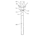
最上端部において、支柱100はクラウン110を支持し、このクラウン110は、ネック部111及び4つの上向きのフィンガ部112を有するフォーク形要素である。意図した通りに使用される場合、各フィンガ部112は、型枠パネル(図示せず)の角部を支持する。更に、クラウン110は、一般的には、クラウン110が支柱100に対して昇降できるように支柱100の最上部のねじジャッキ(図示せず)上に支持される。
At the uppermost end, the
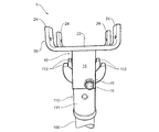
クラウン110は、使用時に型枠シート(図示せず)を支持する、支持ベアラ120(一般的には木材の梁)にはよく適合していない。この場合、アダプタ1を用いることができる。
The
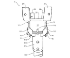
図1〜図5を参照すると、アダプタ1が、取り付け部10と、支持部20を備えることが図示されている。
Referring to FIGS. 1 to 5, the
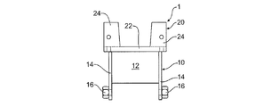
図示された実施形態では、取り付け部10が、アダプタ1をクラウン110に取り付けるために適合されている。従って、取り付け部10は、一般的には箱形状を有しており、一対の側壁12と一対の端部壁14を備える。ここで図14を参照すると、取り付け部10は、クラウン110によって提供されるプラットフォーム114の上に載置されており、クラウン110のフィンガ部112とガイド突起116との間にしっかりと入れ子状に入るサイズとされている。端部壁14は、側壁12より長く、また側壁12より低く、またネック部111のいずれかの側において、クラウン110のフィンガ部112の下のレベルまで延びている。各側壁12はボルト16と組になったナット15を有し、ボルトはナットのなかに螺合され、ボルト16のシャンクの端部をクラウン110のネック部に接触するように動かすことによって、アダプタ1をクラウン110上に固定する。
In the illustrated embodiment, the
取り付け部10の最上に支持されているのは支持部20であり、この支持部は、ベースプレート22と、4つの上向きに延びるベアラガイド24とを備える支持ブラケットの形態を有し、4つの垂直に延びるベアラガイドは2対の対向するベアラガイド24に配置されている。
Supported at the top of the mounting
使用に際しては、アダプタ1の取り付け部10を、上述のようにクラウン110のガイド突起116とフィンガ部112との間のプラットフォーム114上に配置し、ボルト16を締める。次に、ベアラ120を、支持ブラケットのベースプレート22の上でベアラガイド24の間に配置することができる。ベアラガイド24は、ベースプレート22からベアラ120が滑り落ちるのを防止する役目を果たす。型枠のシート(一般的には合板)が、ベアラ120上に支持され得ることになる。
In use, the mounting
型枠パネル(ベアラのないもの)が、支柱100上に支持されることになる場合には、ボルト16は、アダプタ1がクラウン110から取り外し可能となるまで緩めた状態とされる。
When the formwork panel (without the bearer) is to be supported on the
図示されている実施形態では、クラウン110は鋳造部品であり、アダプタ1は組み立てられたものであるが、これらの部品は、このような製造方法で製造されたものに限定されない。
In the illustrated embodiment, the
代替的実施形態では、アダプタは、上述のものと逆の構成、すなわち、ベアラまたはベアラ支持部のいずれかに対して配置されるように適合された取り付け部と、複数の型枠パネルを支持するためのクラウンとを有する構成とすることもできる。 In an alternative embodiment, the adapter supports the opposite configuration as described above, i.e. a fitting adapted to be placed against either the bearer or the bearer support, and a plurality of formwork panels. It can also be set as the structure which has a crown for.
本明細書及び特許請求の範囲の全体において、文脈上別の解釈が必要とならない限り、用語「含む/有する」、「備える」及びその活用形は、記載された整数または整数の群の個数を有することを暗示しているが、他の整数または整数の群の場合を排除するものではないことを理解されたい。 Throughout this specification and claims, the terms “include / have”, “comprise” and their conjugations refer to the number of integers or groups of integers described, unless the context requires otherwise. It is to be understood that this is implied but does not exclude the case of other integers or groups of integers.
本明細書中に記載されたあらゆる従来技術に対する参照は、そのような従来技術が技術常識の一部を形成することの示唆を認めるものとして解釈されないものか、またはそのようなものとして解釈されるべきではない。 References to any prior art described herein are not to be construed as an admission that such prior art forms part of the common general knowledge, or are interpreted as such. Should not.
本発明が、上述の特定の用途における使用に限定されないことは当業者には理解されよう。本発明は、本明細書に記載された特定の要素及び/または特徴に関するその好ましい実施形態に制限されるものではない。本発明は、ここに開示した実施形態に限定されず、特許請求の範囲の請求項によって特定される発明の精神を逸脱することなく、多種の再構成、改変、及び代替的形態を含めて実施可能であることは理解されよう。 Those skilled in the art will appreciate that the present invention is not limited to use in the specific applications described above. The present invention is not limited to its preferred embodiments relating to the specific elements and / or features described herein. The invention is not limited to the embodiments disclosed herein, but may be practiced including various reconfigurations, modifications, and alternative forms without departing from the spirit of the invention as defined by the claims. It will be understood that this is possible.
Claims (17)
前記第1のタイプの型枠支持部に対して前記アダプタを位置付けするための取り付け部を備え、
前記取り付け部は、第2のタイプの型枠支持部を支持することを特徴とするアダプタ。 An adapter for a formwork support structure including a first type formwork support,
An attachment for positioning the adapter relative to the first type of formwork support;
The adapter is characterized in that the mounting portion supports a second type of formwork support.
前記第1のタイプの型枠支持部が、型枠の直接の支持体を提供するように適合されることを特徴とするアダプタ。 The adapter according to claim 1,
An adapter wherein the first type of formwork support is adapted to provide a direct support for the formwork.
前記第1のタイプの型枠支持部が、型枠パネルの直接的な支持を提供するように適合されることを特徴とするアダプタ。 The adapter according to claim 1 or 2,
An adapter wherein the first type of formwork support is adapted to provide direct support of the formwork panel.
前記第1のタイプの型枠支持部が、1個の垂直支持体であるクラウンから延びる複数の上向きフィンガ部を含むことを特徴とするアダプタ。 The adapter according to any one of claims 1 to 3,
The adapter according to claim 1, wherein the first type of formwork support includes a plurality of upward finger portions extending from a crown which is one vertical support.
前記第2のタイプの型枠支持部は、型枠パネルの間接的な支持を提供するように適合されることを特徴とするアダプタ。 The adapter according to any one of claims 1 to 4,
The adapter of claim 2, wherein the second type of formwork support is adapted to provide indirect support of the formwork panel.
前記第2のタイプの型枠支持部は、型枠のためのベアラの支持部であることを特徴とするアダプタ。 It is an adapter as described in any one of Claims 1-5,
The adapter according to claim 2, wherein the second type mold support is a bearer support for the mold.
前記第1のタイプの型枠支持部が、1個の垂直支持体であるクラウンから延びる複数の上向きフィンガ部を含み、
前記取り付け部は、前記クラウンの前記フィンガ部の間に入れ子状に入るように適合されることを特徴とするアダプタ。 It is an adapter as described in any one of Claims 4-6,
The first type of formwork support includes a plurality of upward finger portions extending from a crown which is a single vertical support;
The adapter, wherein the mounting portion is adapted to nest between the finger portions of the crown.
前記取り付け部は、前記第1のタイプの型枠支持部に対して前記アダプタを固定するための固定手段を含むことを特徴とするアダプタ。 It is an adapter as described in any one of Claims 1-7,
The adapter is characterized in that the attachment portion includes a fixing means for fixing the adapter to the first type mold support.
前記第2のタイプの型枠支持部が、U字形状を有することを特徴とするアダプタ。 The adapter according to any one of claims 6 to 8,
The adapter, wherein the second type of formwork support has a U-shape.
前記第2のタイプの型枠支持部が、ベース部と、複数の上向きに延びるベアラガイドとを備えることを特徴とするアダプタ。 The adapter according to any one of claims 6 to 9,
The adapter according to claim 2, wherein the second type of formwork support part includes a base part and a plurality of upwardly extending bearer guides.
前記第1のタイプの型枠支持部が、型枠の間接的な支持を提供するように適合されることを特徴とするアダプタ。 The adapter according to claim 1,
An adapter wherein the first type of formwork support is adapted to provide indirect support of the formwork.
前記第2のタイプの型枠支持部が、型枠の直接的な支持を提供するように適合されることを特徴とするアダプタ。 The adapter according to claim 11, wherein
An adapter wherein the second type of formwork support is adapted to provide direct support of the formwork.
前記第2のタイプの型枠支持部が、1個の垂直支持体であるクラウンから延びる複数の上向きフィンガ部を含むことを特徴とするアダプタ。 The adapter according to claim 11 or 12,
The adapter according to claim 2, wherein the second type of formwork support includes a plurality of upward finger portions extending from a crown which is a single vertical support.
前記第1のタイプの型枠支持部は、型枠のためのベアラの支持部であることを特徴とするアダプタ。 It is an adapter as described in any one of Claims 11-13,
The adapter according to claim 1, wherein the first type of formwork support part is a bearer support part for a formwork.
前記クラウンに対して前記アダプタを位置付けするための取り付け部を備え、
前記取り付け部は、ベアラ支持部を支持することを特徴とするアダプタ。 An adapter for a crown-type formwork support that is a vertical support,
An attachment for positioning the adapter relative to the crown;
The adapter is characterized in that the attachment portion supports a bearer support portion.
前記ベアラ支持部に対して前記アダプタを位置付けするための取り付け部を備え、
前記取り付け部は、垂直支持体であるクラウンを支持することを特徴とするアダプタ。 An adapter for the bearer support,
An attachment portion for positioning the adapter with respect to the bearer support portion;
The adapter is characterized in that the mounting portion supports a crown which is a vertical support.
垂直支持体であるクラウンタイプの型枠支持体に対して前記ベアラ支持ブラケットを位置付けするための取り付け部を備え、
前記取り付け部は、ベアラ支持部を支持することを特徴とするフレームワークベアラ支持ブラケット。 A framework bearer support bracket,
A mounting portion for positioning the bearer support bracket with respect to a crown type formwork support that is a vertical support;
The attachment part supports a bearer support part, The framework bearer support bracket characterized by the above-mentioned.
Applications Claiming Priority (3)
| Application Number | Priority Date | Filing Date | Title |
|---|---|---|---|
| AU2014900721 | 2014-03-04 | ||
| AU2014900721A AU2014900721A0 (en) | 2014-03-04 | A framework bearer support bracket | |
| PCT/AU2015/000117 WO2015131229A1 (en) | 2014-03-04 | 2015-03-03 | An adapter for a formwork support structure |
Publications (2)
| Publication Number | Publication Date |
|---|---|
| JP2017507264A true JP2017507264A (en) | 2017-03-16 |
| JP6573625B2 JP6573625B2 (en) | 2019-09-11 |
Family
ID=54054259
Family Applications (1)
| Application Number | Title | Priority Date | Filing Date |
|---|---|---|---|
| JP2016555567A Expired - Fee Related JP6573625B2 (en) | 2014-03-04 | 2015-03-03 | Adapter for formwork support structure |
Country Status (14)
| Country | Link |
|---|---|
| US (1) | US10119282B2 (en) |
| EP (1) | EP3114292B1 (en) |
| JP (1) | JP6573625B2 (en) |
| KR (1) | KR20160129037A (en) |
| CN (1) | CN106103864B (en) |
| AU (1) | AU2015226826B2 (en) |
| CA (1) | CA2940051A1 (en) |
| DK (1) | DK3114292T3 (en) |
| MY (1) | MY181541A (en) |
| NZ (1) | NZ724851A (en) |
| PT (1) | PT3114292T (en) |
| RU (1) | RU2684266C2 (en) |
| SG (1) | SG11201607063PA (en) |
| WO (1) | WO2015131229A1 (en) |
Families Citing this family (11)
| Publication number | Priority date | Publication date | Assignee | Title |
|---|---|---|---|---|
| CN108337895B (en) | 2015-07-24 | 2021-02-09 | 拉链墙有限责任公司 | Partition mounting system including head coupler with adjustable head length and head position |
| ITUB20156234A1 (en) * | 2015-12-04 | 2017-06-04 | Faresin Building S P A | ANTI-LIFTING JOINT SYSTEM FOR THE REVERSIBLE JOINTING OF ELEMENTS FOR THE CREATION OF A CASSERATION FOR JETS OF SOLAI |
| CA2962013A1 (en) * | 2016-03-24 | 2017-09-24 | Faresin Building S.P.A. | Formwork for performing horizontal castings for the provision of floors |
| ES2677695B1 (en) * | 2017-02-03 | 2019-03-22 | Sist Tecnicos De Encofrados Sa | SPINDLE HEAD |
| ES2677793B1 (en) * | 2017-02-06 | 2019-03-22 | Sist Tecnicos De Encofrados Sa | HEAD FOR BEAM ENCOUNTERS |
| KR101976352B1 (en) | 2017-03-30 | 2019-05-08 | 노용규 | Elastic clip for yoke |
| IT201700099585A1 (en) * | 2017-09-06 | 2019-03-06 | Faresin Building S P A | IMPROVED SUPPORT DEVICE FOR FORMWORK SUPPORT BEAMS FOR FLOORS |
| IT201800003425A1 (en) * | 2018-03-12 | 2019-09-12 | Faresin Formwork S P A | "PERFECTED SUPPORT DEVICE, OF THE FALL-HEAD TYPE, FOR SUPPORT BEAMS OF FORMWORKS FOR FLOORS, EQUIPMENT INCLUDING THIS DEVICE AND SUPPORT BEAM TO BE ASSOCIATED WITH THE DEVICE" |
| KR102048299B1 (en) * | 2019-07-25 | 2020-01-08 | 성진이앤티 주식회사 | Guide plate provided in the module frame for collecting oil sand |
| CN111365042A (en) * | 2020-03-13 | 2020-07-03 | 重庆工程职业技术学院 | Large-section tunnel supporting device |
| CN112502481A (en) * | 2020-11-27 | 2021-03-16 | 上海建工五建集团有限公司 | Longitudinal and transverse dual-purpose supporting plate and construction method |
Citations (8)
| Publication number | Priority date | Publication date | Assignee | Title |
|---|---|---|---|---|
| GB741730A (en) * | 1952-09-10 | 1955-12-14 | Enoch Charles Williams | Adjustable supports for shuttering, centring and the like |
| JPS4630338Y1 (en) * | 1967-07-29 | 1971-10-20 | ||
| JPS62131550U (en) * | 1986-02-13 | 1987-08-19 | ||
| JPH05848U (en) * | 1991-06-19 | 1993-01-08 | 中央ビルト工業株式会社 | support |
| DE19636091A1 (en) * | 1996-09-05 | 1998-03-12 | Hollmann Niels | Frame especially for a platform or a scaffold or for decking formwork used in construction |
| US20040075042A1 (en) * | 2001-04-03 | 2004-04-22 | Alberto Arozena Bergaretxe | Floor and roof formwork system |
| US20100193663A1 (en) * | 2007-07-31 | 2010-08-05 | Paschal-Werk G. Maier Gmbh | Ceiling formwork having supporting means for formwork panels |
| WO2013139102A1 (en) * | 2012-03-19 | 2013-09-26 | 山东普瑞玛模板有限公司 | Early-removal formwork system for concreting of constructions comprising beams, plates and columns |
Family Cites Families (32)
| Publication number | Priority date | Publication date | Assignee | Title |
|---|---|---|---|---|
| US607867A (en) * | 1898-07-26 | marshall | ||
| US813318A (en) * | 1904-05-03 | 1906-02-20 | Thomas F Mccarthy | Column. |
| US813253A (en) * | 1905-06-15 | 1906-02-20 | John H Sullivan | Mold. |
| US999908A (en) * | 1910-08-15 | 1911-08-08 | Charles P Tatro | Extension tree-prop. |
| US1258409A (en) * | 1915-08-28 | 1918-03-05 | Thomas Hill | Building structure. |
| US1490461A (en) * | 1918-10-13 | 1924-04-15 | Blawknox Company | Floor-mold form |
| US1660496A (en) * | 1925-08-22 | 1928-02-28 | Arthur H Symons | Head member for shores |
| US1612516A (en) * | 1926-02-15 | 1926-12-28 | Henry H Lampert | Thead |
| US1612517A (en) * | 1926-03-13 | 1926-12-28 | Henry H Lampert | Post cap |
| US1746027A (en) * | 1927-12-01 | 1930-02-04 | Patrick J Cannon | Sidewalk bridge |
| US2331247A (en) * | 1943-03-11 | 1943-10-05 | Symons Clamp & Mfg Company | Shore head structure |
| US3001754A (en) * | 1958-11-26 | 1961-09-26 | Flum Paul Merchandising Ideas | Mounting means for telescoping pole support |
| US3132833A (en) * | 1961-05-19 | 1964-05-12 | James N Mclaughlin | Jack |
| US3203660A (en) * | 1964-08-26 | 1965-08-31 | Symons Mfg Co | T-head stabilizer for a shore |
| DE1957913C3 (en) * | 1969-11-12 | 1974-04-25 | Mannesmann Leichtbau Gmbh, 8000 Muenchen | Composable framework support |
| GB1473846A (en) * | 1973-06-29 | 1977-05-18 | Acrow Ltd | Supports for concrete formwork |
| US4036466A (en) * | 1973-12-20 | 1977-07-19 | Symons Corporation | Flying deck-type concrete form installation |
| NO153901C (en) * | 1983-11-07 | 1986-06-11 | Kristoffer Idland | SOEYLES SHOES, AND PROCEDURES FOR FOLDING SOEYLES SHOES. |
| US4741505A (en) * | 1985-03-22 | 1988-05-03 | Anderson Carl E | Scaffolding arrangement |
| US5031724A (en) * | 1989-12-29 | 1991-07-16 | James E. Wright | Shoring frame pillar |
| US5520360A (en) * | 1994-10-26 | 1996-05-28 | Wensman; Scott M. | Adjustable jack stand |
| ES2143377B1 (en) * | 1997-09-15 | 2000-12-01 | Ulma C Y E S Coop | PERFECTED HORIZONTAL FORMWORK. |
| US6832746B2 (en) * | 2001-08-10 | 2004-12-21 | Wilian Holding Company | Attachment device for concrete shoring apparatus |
| DE602005022505D1 (en) * | 2005-02-23 | 2010-09-02 | Ulma C Y E S Coop | SCOPE PANEL FORMWORK SYSTEM |
| CN200961354Y (en) * | 2006-06-21 | 2007-10-17 | 黄国威 | Roof-supporting base with bottom plate |
| DE102006055306B4 (en) * | 2006-11-23 | 2010-10-07 | Peri Gmbh | Support head for slab formwork |
| US7922145B2 (en) * | 2008-02-06 | 2011-04-12 | Swa Holding Company, Inc. | Adjustable support stand for pre-cast concrete wall forms |
| CN202012191U (en) * | 2010-12-20 | 2011-10-19 | 北京市建筑工程研究院有限责任公司 | Formwork early-dismantling tool type support |
| CN202007526U (en) * | 2011-04-06 | 2011-10-12 | 中国葛洲坝集团股份有限公司 | Adjustable supporting device for top formwork |
| CN202731289U (en) * | 2012-07-03 | 2013-02-13 | 中国建筑股份有限公司 | Early dismounting device for aluminum alloy top plate |
| CN202731290U (en) * | 2012-08-09 | 2013-02-13 | 中国二十二冶集团有限公司 | Support device for steel-wood combination keel template |
| CN103195241B (en) * | 2013-04-18 | 2014-04-02 | 深圳市广胜达建筑工程有限公司 | Early removal support device for constructional engineering |
-
2015
- 2015-03-03 CA CA2940051A patent/CA2940051A1/en not_active Abandoned
- 2015-03-03 AU AU2015226826A patent/AU2015226826B2/en active Active
- 2015-03-03 KR KR1020167026917A patent/KR20160129037A/en active IP Right Grant
- 2015-03-03 JP JP2016555567A patent/JP6573625B2/en not_active Expired - Fee Related
- 2015-03-03 PT PT15758062T patent/PT3114292T/en unknown
- 2015-03-03 DK DK15758062.2T patent/DK3114292T3/en active
- 2015-03-03 MY MYPI2016703086A patent/MY181541A/en unknown
- 2015-03-03 US US15/123,362 patent/US10119282B2/en active Active
- 2015-03-03 NZ NZ724851A patent/NZ724851A/en unknown
- 2015-03-03 WO PCT/AU2015/000117 patent/WO2015131229A1/en active Application Filing
- 2015-03-03 RU RU2016137822A patent/RU2684266C2/en active
- 2015-03-03 CN CN201580011886.2A patent/CN106103864B/en not_active Expired - Fee Related
- 2015-03-03 EP EP15758062.2A patent/EP3114292B1/en active Active
- 2015-03-03 SG SG11201607063PA patent/SG11201607063PA/en unknown
Patent Citations (8)
| Publication number | Priority date | Publication date | Assignee | Title |
|---|---|---|---|---|
| GB741730A (en) * | 1952-09-10 | 1955-12-14 | Enoch Charles Williams | Adjustable supports for shuttering, centring and the like |
| JPS4630338Y1 (en) * | 1967-07-29 | 1971-10-20 | ||
| JPS62131550U (en) * | 1986-02-13 | 1987-08-19 | ||
| JPH05848U (en) * | 1991-06-19 | 1993-01-08 | 中央ビルト工業株式会社 | support |
| DE19636091A1 (en) * | 1996-09-05 | 1998-03-12 | Hollmann Niels | Frame especially for a platform or a scaffold or for decking formwork used in construction |
| US20040075042A1 (en) * | 2001-04-03 | 2004-04-22 | Alberto Arozena Bergaretxe | Floor and roof formwork system |
| US20100193663A1 (en) * | 2007-07-31 | 2010-08-05 | Paschal-Werk G. Maier Gmbh | Ceiling formwork having supporting means for formwork panels |
| WO2013139102A1 (en) * | 2012-03-19 | 2013-09-26 | 山东普瑞玛模板有限公司 | Early-removal formwork system for concreting of constructions comprising beams, plates and columns |
Also Published As
| Publication number | Publication date |
|---|---|
| RU2016137822A3 (en) | 2018-09-18 |
| RU2684266C2 (en) | 2019-04-04 |
| EP3114292A4 (en) | 2017-10-18 |
| RU2016137822A (en) | 2018-04-04 |
| SG11201607063PA (en) | 2016-09-29 |
| AU2015226826B2 (en) | 2019-03-14 |
| PT3114292T (en) | 2019-08-02 |
| CN106103864B (en) | 2019-03-01 |
| JP6573625B2 (en) | 2019-09-11 |
| CN106103864A (en) | 2016-11-09 |
| CA2940051A1 (en) | 2015-09-11 |
| NZ724851A (en) | 2021-12-24 |
| AU2015226826A1 (en) | 2016-10-13 |
| MY181541A (en) | 2020-12-28 |
| EP3114292B1 (en) | 2019-05-01 |
| WO2015131229A1 (en) | 2015-09-11 |
| KR20160129037A (en) | 2016-11-08 |
| DK3114292T3 (en) | 2019-07-29 |
| US20170067263A1 (en) | 2017-03-09 |
| US10119282B2 (en) | 2018-11-06 |
| EP3114292A1 (en) | 2017-01-11 |
Similar Documents
| Publication | Publication Date | Title |
|---|---|---|
| JP6573625B2 (en) | Adapter for formwork support structure | |
| CN212453614U (en) | Formwork support system | |
| US9279260B2 (en) | Modular panel concrete form for self-lifting concrete form system | |
| PH12014501858A1 (en) | Preformed formwork for forming concrete floor slab for a height adjustable shipping container building structure | |
| US20150197949A1 (en) | Formwork support element | |
| CN206562761U (en) | Floor post-cast strip boatswain chair mould | |
| TWM556760U (en) | Sealing structure for the bottom of a beam space between precast panels | |
| CN203475835U (en) | Fixing part for concrete surface slab staggering beamed formwork | |
| KR101362345B1 (en) | Stairway form fixing tool | |
| US10533330B2 (en) | Concrete formwork and a formwork support bracket for forming a suspended floor slab | |
| KR20180107396A (en) | soffit length for fixing beam | |
| CN203547135U (en) | Fixing piece for slab staggering beamless formwork on concrete surface | |
| JP2006002542A (en) | Auxiliary member for form | |
| TH71195A (en) | Formwork units and formwork structures for creating concrete slabs in three-dimensional structures using formwork units. | |
| JP2004084355A (en) | Ceiling joist supporting structure for housing unit | |
| TWM336304U (en) | Supporting apparatus for large span type level template | |
| JPH02289766A (en) | Leveling device for concrete | |
| TH2728A3 (en) | Formwork for concrete structures | |
| TH2728C3 (en) | Formwork for concrete structures |
Legal Events
| Date | Code | Title | Description |
|---|---|---|---|
| A521 | Request for written amendment filed |
Free format text: JAPANESE INTERMEDIATE CODE: A523 Effective date: 20160906 |
|
| A621 | Written request for application examination |
Free format text: JAPANESE INTERMEDIATE CODE: A621 Effective date: 20180227 |
|
| A977 | Report on retrieval |
Free format text: JAPANESE INTERMEDIATE CODE: A971007 Effective date: 20181227 |
|
| A131 | Notification of reasons for refusal |
Free format text: JAPANESE INTERMEDIATE CODE: A131 Effective date: 20190115 |
|
| A521 | Request for written amendment filed |
Free format text: JAPANESE INTERMEDIATE CODE: A523 Effective date: 20190326 |
|
| TRDD | Decision of grant or rejection written | ||
| A01 | Written decision to grant a patent or to grant a registration (utility model) |
Free format text: JAPANESE INTERMEDIATE CODE: A01 Effective date: 20190723 |
|
| A61 | First payment of annual fees (during grant procedure) |
Free format text: JAPANESE INTERMEDIATE CODE: A61 Effective date: 20190813 |
|
| R150 | Certificate of patent or registration of utility model |
Ref document number: 6573625 Country of ref document: JP Free format text: JAPANESE INTERMEDIATE CODE: R150 |
|
| LAPS | Cancellation because of no payment of annual fees |