EP2952637A2 - Drain remediation - Google Patents
Drain remediation Download PDFInfo
- Publication number
- EP2952637A2 EP2952637A2 EP15170618.1A EP15170618A EP2952637A2 EP 2952637 A2 EP2952637 A2 EP 2952637A2 EP 15170618 A EP15170618 A EP 15170618A EP 2952637 A2 EP2952637 A2 EP 2952637A2
- Authority
- EP
- European Patent Office
- Prior art keywords
- teeth
- drum
- drain
- along
- strips
- Prior art date
- Legal status (The legal status is an assumption and is not a legal conclusion. Google has not performed a legal analysis and makes no representation as to the accuracy of the status listed.)
- Granted
Links
- 238000005067 remediation Methods 0.000 title claims abstract description 18
- 239000000463 material Substances 0.000 claims abstract description 34
- 238000013019 agitation Methods 0.000 claims abstract description 16
- 238000000034 method Methods 0.000 claims abstract description 5
- 239000002352 surface water Substances 0.000 description 3
- XLYOFNOQVPJJNP-UHFFFAOYSA-N water Substances O XLYOFNOQVPJJNP-UHFFFAOYSA-N 0.000 description 3
- 244000025254 Cannabis sativa Species 0.000 description 1
- 230000001010 compromised effect Effects 0.000 description 1
- 239000002245 particle Substances 0.000 description 1
Images

Classifications
-
- E—FIXED CONSTRUCTIONS
- E02—HYDRAULIC ENGINEERING; FOUNDATIONS; SOIL SHIFTING
- E02F—DREDGING; SOIL-SHIFTING
- E02F5/00—Dredgers or soil-shifting machines for special purposes
- E02F5/28—Dredgers or soil-shifting machines for special purposes for cleaning watercourses or other ways
- E02F5/282—Dredgers or soil-shifting machines for special purposes for cleaning watercourses or other ways with rotating cutting or digging tools
-
- E—FIXED CONSTRUCTIONS
- E03—WATER SUPPLY; SEWERAGE
- E03F—SEWERS; CESSPOOLS
- E03F7/00—Other installations or implements for operating sewer systems, e.g. for preventing or indicating stoppage; Emptying cesspools
-
- E—FIXED CONSTRUCTIONS
- E01—CONSTRUCTION OF ROADS, RAILWAYS, OR BRIDGES
- E01C—CONSTRUCTION OF, OR SURFACES FOR, ROADS, SPORTS GROUNDS, OR THE LIKE; MACHINES OR AUXILIARY TOOLS FOR CONSTRUCTION OR REPAIR
- E01C23/00—Auxiliary devices or arrangements for constructing, repairing, reconditioning, or taking-up road or like surfaces
- E01C23/06—Devices or arrangements for working the finished surface; Devices for repairing or reconditioning the surface of damaged paving; Recycling in place or on the road
- E01C23/065—Recycling in place or on the road, i.e. hot or cold reprocessing of paving in situ or on the traffic surface, with or without adding virgin material or lifting of salvaged material; Repairs or resurfacing involving at least partial reprocessing of the existing paving
-
- E—FIXED CONSTRUCTIONS
- E02—HYDRAULIC ENGINEERING; FOUNDATIONS; SOIL SHIFTING
- E02F—DREDGING; SOIL-SHIFTING
- E02F7/00—Equipment for conveying or separating excavated material
- E02F7/06—Delivery chutes or screening plants or mixing plants mounted on dredgers or excavators
Definitions
- the invention relates to an apparatus and method for remediation of drains by agitation of drain material.
- a common method of draining water, such as rainwater, away from a surface or structure is the use of French drains, which comprise a trench, filled with material such as gravel and stones. Surface water runs into the drain and seeps down through the drain material. The water is therefore directed away from the area surrounding the drain.
- Such drains are commonly used for the drainage of carriageways, where a drain trench is provided along an edge of the carriageway. Surface water from the carriageway is guided into the drain and seeps down through the drain material. The water is therefore directed away from carriageway, thus reducing the risk of flooding of the carriageway.
- Drains installed along carriageways are typically replaced every 10 years. However, in between replacements, the performance of the drains can be compromised. This is mainly due to clogging of the material used to fill the drain. If this is not corrected, surface water can collect on the carriageway, which has the potential for causing accidents.
- a drain remediation tool comprising a housing providing an aperture, a rotatable drum at least partially disposed within the housing, a drive shaft attached to the drum and adapted to be attached to drive apparatus for rotation of the drum and a plurality of teeth attached to the drum and protruding therefrom through the aperture of the housing, which, on rotation of the drum, sequentially penetrate material in a drain causing agitation of the material and remediation of the drain.
- agitation of material of a drain can significantly improve the drain's performance.
- the agitation has been found to at least partially release clogging of the material in the drain trench which allows the drain to work more freely and thereby remediates the drain.
- the plurality of teeth may be each substantially in the shape of a triangle, particularly a right-angled triangle.
- the teeth may have a width of approximately 40mm.
- the teeth may have a length of approximately 165mm. Agitation of the material of the drain is therefore to a depth in the trench of at least approximately 165mm, which has been found to provide sufficient declogging of the drain material to remediate the drain.
- the plurality of teeth may be arranged on the drum in a manner to carry some of the material of the drain over the drum.
- the plurality of teeth may be arranged along and around the cylindrical drum.
- the plurality of teeth may comprise two or more teeth provided on each of a plurality of strips along the cylindrical drum. For each strip the two or more teeth may be spaced along the strip. For a pair of adjacent strips the two or more teeth on a first strip may be offset along the cylindrical drum from the two or more teeth on a second strip.
- the plurality of teeth may additionally comprise a single tooth provided on at least one strip along the cylindrical drum.
- the single tooth may be provided on the at least one strip at a position approximately midway along the strip.
- the plurality of strips along the cylindrical drum may be spaced around the cylindrical drum.
- the plurality of strips may be spaced at substantially equal intervals around the cylindrical drum.
- the plurality of teeth may comprise a first single tooth provided on a first strip along the cylindrical drum, a second single tooth provided on a second strip along the cylindrical drum and six pairs of teeth provided on third to eighth strips along the cylindrical drum.
- the first and second strips may be spaced around the cylindrical drum at an interval of approximately 180 degrees.
- the third, fourth and fifth strips may be spaced around a first side of the cylindrical drum at approximately equal intervals between the first and second strips.
- the sixth, seventh and eighth strips may be spaced around a second side of the cylindrical drum at approximately equal intervals between the first and second strips.
- the first and second single teeth may be provided on the first and second strips at positions approximately midway along each strip.
- the pair of teeth may be spaced along the strip.
- each pair of teeth may be offset along the cylindrical drum to provide teeth along the length of the cylindrical drum.
- each pair of teeth may be offset along the cylindrical drum to provide teeth along the length of the cylindrical drum.
- the housing may comprise an approximate partial cylinder with closed ends.
- the aperture may be provided in a wall of the partial cylinder.
- the housing may be provided with a levelling plate which acts to at least partially level the material of the drain after agitation.
- the housing may be provided with an attachment device adapted to attach to a machine for supporting the drain remediation tool in position over the drain in use.
- the drive shaft may protrude through a further aperture in the housing for attachment to the drive apparatus.
- a method of remediating a drain comprising causing agitation of material in the drain using a drain remediation tool of the first aspect of the invention.
- the drain remediation tool 1 comprises a housing 3, a rotatable drum 5, a drive shaft 7 and a plurality of teeth 9.
- the housing 3 comprises an approximate partial cylinder 11 with closed ends provided by first and second end plates 13.
- the partial cylinder 11 provides an aperture 15.
- the housing 3 further comprises a levelling plate 17 and an attachment device 19 adapted to connect to a machine in use.
- the rotatable drum 5 is substantially cylindrical and is disposed within the housing 3, as shown.
- the drive shaft 7 is attached to the drum 5.
- the drive shaft 7 protrudes through a further aperture in the housing 3, as shown, and is attached to a drive apparatus (not shown) for rotation of the drum 5.
- the drive apparatus comprises a gearbox and a motor (not shown).
- the plurality of teeth 9 are attached to the drum 5 and protrude therefrom, as shown, so that they project through the aperture 15 in the wall of the partial cylinder 11 of the housing 3.
- the teeth 9 are substantially in the shape of a right-angled triangle, with, in this embodiment, a width of approximately 40mm and a length of approximately 165mm.
- the plurality of teeth 9 are arranged along and around the cylindrical drum 5 in a manner to carry some of the material of the drain over the drum 5.
- the plurality of teeth 9 comprise a first single tooth provided on a first strip along the cylindrical drum 5, a second single tooth provided on a second strip along the cylindrical drum 5 and six pairs of teeth provided on third to eighth strips along the cylindrical drum 5.
- the first and second strips are spaced around the cylindrical drum 5 at an interval of approximately 180 degrees.
- the third, fourth and fifth strips are spaced around a first side of the cylindrical drum 5 at approximately equal intervals between the first and second strips.
- the sixth, seventh and eighth strips are spaced around a second side of the cylindrical drum 5 at approximately equal intervals between the first and second strips.
- the first and second single teeth are provided on the first and second strips at positions approximately midway along each strip, i.e. midway along the cylindrical drum 5.
- the pair of teeth are spaced along the strip at positions approximately 300mm apart.
- each pair of teeth are offset by approximately 85mm along the cylindrical drum 5 to provide teeth along the length of the cylindrical drum 5, as shown.
- each pair of teeth is offset by approximately 85mm along the cylindrical drum 5 to provide teeth along the length of the cylindrical drum 5, as shown.
- the drain remediation tool 1 is attached to a machine 21 for use.
- the machine is a tracked vehicle, but other vehicles or machines could be used for operation of the tool.
- the attachment device 19 of the housing 3 attaches the tool 1 to an arm 23 of the tracked vehicle 21.
- the drive apparatus (not shown) is attached to a power supply (not shown) of the vehicle 21 for rotation of the drum 5.
- the drain remediation tool 1 is supported in position over a drain such that the aperture 15 of the housing 3 is placed adjacent a trench of the drain and the plurality of teeth 9 protrude through the aperture 15 into material in the drain trench.
- the tool 1 is moved along the drain by the vehicle 21.
- the drum 5 rotates and the plurality of teeth 9 sequentially penetrate material in the drain causing agitation of the material.
- agitation of the material of the drain is therefore to a depth in the trench of at least approximately 165mm.
- the arrangement of the plurality of teeth 9 on the drum 5 is such that some drain material is carried over the drum 5 and back into the drain trench.
- the result of this and the agitation is a breaking apart of particles of the drain material which have become gelled together over time by dirt and grass.
- the housing 3 is provided around the drum 5 to aid in replacement of the material back into the drain trench and to protect users of the drain remediation tool 1.
- the levelling plate 17 of the housing 3 follows the drum 5 and at least partially levels the material back into place in the drain trench after agitation.
Abstract
Description
- The invention relates to an apparatus and method for remediation of drains by agitation of drain material.
- A common method of draining water, such as rainwater, away from a surface or structure is the use of French drains, which comprise a trench, filled with material such as gravel and stones. Surface water runs into the drain and seeps down through the drain material. The water is therefore directed away from the area surrounding the drain.
- Such drains are commonly used for the drainage of carriageways, where a drain trench is provided along an edge of the carriageway. Surface water from the carriageway is guided into the drain and seeps down through the drain material. The water is therefore directed away from carriageway, thus reducing the risk of flooding of the carriageway.
- Drains installed along carriageways are typically replaced every 10 years. However, in between replacements, the performance of the drains can be compromised. This is mainly due to clogging of the material used to fill the drain. If this is not corrected, surface water can collect on the carriageway, which has the potential for causing accidents.
- According to a first aspect of the invention there is provided a drain remediation tool comprising a housing providing an aperture, a rotatable drum at least partially disposed within the housing, a drive shaft attached to the drum and adapted to be attached to drive apparatus for rotation of the drum and a plurality of teeth attached to the drum and protruding therefrom through the aperture of the housing, which, on rotation of the drum, sequentially penetrate material in a drain causing agitation of the material and remediation of the drain.
- It has been found that agitation of material of a drain can significantly improve the drain's performance. The agitation has been found to at least partially release clogging of the material in the drain trench which allows the drain to work more freely and thereby remediates the drain.
- The plurality of teeth may be each substantially in the shape of a triangle, particularly a right-angled triangle. The teeth may have a width of approximately 40mm. The teeth may have a length of approximately 165mm. Agitation of the material of the drain is therefore to a depth in the trench of at least approximately 165mm, which has been found to provide sufficient declogging of the drain material to remediate the drain.
- The plurality of teeth may be arranged on the drum in a manner to carry some of the material of the drain over the drum.
- The plurality of teeth may be arranged along and around the cylindrical drum. The plurality of teeth may comprise two or more teeth provided on each of a plurality of strips along the cylindrical drum. For each strip the two or more teeth may be spaced along the strip. For a pair of adjacent strips the two or more teeth on a first strip may be offset along the cylindrical drum from the two or more teeth on a second strip. The plurality of teeth may additionally comprise a single tooth provided on at least one strip along the cylindrical drum. The single tooth may be provided on the at least one strip at a position approximately midway along the strip. The plurality of strips along the cylindrical drum may be spaced around the cylindrical drum. The plurality of strips may be spaced at substantially equal intervals around the cylindrical drum.
- The plurality of teeth may comprise a first single tooth provided on a first strip along the cylindrical drum, a second single tooth provided on a second strip along the cylindrical drum and six pairs of teeth provided on third to eighth strips along the cylindrical drum. The first and second strips may be spaced around the cylindrical drum at an interval of approximately 180 degrees. The third, fourth and fifth strips may be spaced around a first side of the cylindrical drum at approximately equal intervals between the first and second strips. The sixth, seventh and eighth strips may be spaced around a second side of the cylindrical drum at approximately equal intervals between the first and second strips. The first and second single teeth may be provided on the first and second strips at positions approximately midway along each strip. For each of the third to eighth strips the pair of teeth may be spaced along the strip. For the third, fourth and fifth strips each pair of teeth may be offset along the cylindrical drum to provide teeth along the length of the cylindrical drum. For the sixth, seventh and eighth strips each pair of teeth may be offset along the cylindrical drum to provide teeth along the length of the cylindrical drum.
- It will be appreciated that other arrangements of the plurality of teeth on the drum may be used, such that the teeth will agitate the material of the drain and carry some of the material of the drain over the drum.
- The housing may comprise an approximate partial cylinder with closed ends. The aperture may be provided in a wall of the partial cylinder. The housing may be provided with a levelling plate which acts to at least partially level the material of the drain after agitation. The housing may be provided with an attachment device adapted to attach to a machine for supporting the drain remediation tool in position over the drain in use.
- The drive shaft may protrude through a further aperture in the housing for attachment to the drive apparatus.
- According to a second aspect of the invention there is provided a method of remediating a drain comprising causing agitation of material in the drain using a drain remediation tool of the first aspect of the invention.
- An embodiment of the invention will now be described by way of example only, with reference to the accompanying drawings, in which:
-
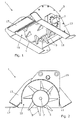
Figure 1 is a perspective view of the drain remediation tool according to the first aspect of the invention; -
Figure 2 is a cross sectional view of the tool ofFigure 1 , and -
Figure 3 is a schematic representation of the tool ofFigures 1 and 2 attached to a machine for use. - Referring to
Figures 1 and 2 , thedrain remediation tool 1 comprises ahousing 3, arotatable drum 5, adrive shaft 7 and a plurality ofteeth 9. - The
housing 3 comprises an approximatepartial cylinder 11 with closed ends provided by first andsecond end plates 13. Thepartial cylinder 11 provides anaperture 15. Thehousing 3 further comprises alevelling plate 17 and anattachment device 19 adapted to connect to a machine in use. - The
rotatable drum 5 is substantially cylindrical and is disposed within thehousing 3, as shown. Thedrive shaft 7 is attached to thedrum 5. Thedrive shaft 7 protrudes through a further aperture in thehousing 3, as shown, and is attached to a drive apparatus (not shown) for rotation of thedrum 5. The drive apparatus comprises a gearbox and a motor (not shown). - The plurality of
teeth 9 are attached to thedrum 5 and protrude therefrom, as shown, so that they project through theaperture 15 in the wall of thepartial cylinder 11 of thehousing 3. Theteeth 9 are substantially in the shape of a right-angled triangle, with, in this embodiment, a width of approximately 40mm and a length of approximately 165mm. - The plurality of
teeth 9 are arranged along and around thecylindrical drum 5 in a manner to carry some of the material of the drain over thedrum 5. The plurality ofteeth 9 comprise a first single tooth provided on a first strip along thecylindrical drum 5, a second single tooth provided on a second strip along thecylindrical drum 5 and six pairs of teeth provided on third to eighth strips along thecylindrical drum 5. The first and second strips are spaced around thecylindrical drum 5 at an interval of approximately 180 degrees. The third, fourth and fifth strips are spaced around a first side of thecylindrical drum 5 at approximately equal intervals between the first and second strips. The sixth, seventh and eighth strips are spaced around a second side of thecylindrical drum 5 at approximately equal intervals between the first and second strips. The first and second single teeth are provided on the first and second strips at positions approximately midway along each strip, i.e. midway along thecylindrical drum 5. For each of the third to eighth strips the pair of teeth are spaced along the strip at positions approximately 300mm apart. For the third, fourth and fifth strips each pair of teeth are offset by approximately 85mm along thecylindrical drum 5 to provide teeth along the length of thecylindrical drum 5, as shown. For the sixth, seventh and eighth strips each pair of teeth is offset by approximately 85mm along thecylindrical drum 5 to provide teeth along the length of thecylindrical drum 5, as shown. - Referring to
Figure 3 , thedrain remediation tool 1 is attached to amachine 21 for use. In this embodiment, the machine is a tracked vehicle, but other vehicles or machines could be used for operation of the tool. Theattachment device 19 of thehousing 3 attaches thetool 1 to anarm 23 of the trackedvehicle 21. The drive apparatus (not shown) is attached to a power supply (not shown) of thevehicle 21 for rotation of thedrum 5. - In use, the
drain remediation tool 1 is supported in position over a drain such that theaperture 15 of thehousing 3 is placed adjacent a trench of the drain and the plurality ofteeth 9 protrude through theaperture 15 into material in the drain trench. Thetool 1 is moved along the drain by thevehicle 21. As thetool 1 moves along the trench of the drain, thedrum 5 rotates and the plurality ofteeth 9 sequentially penetrate material in the drain causing agitation of the material. As the teeth length is 165mm, agitation of the material of the drain is therefore to a depth in the trench of at least approximately 165mm. The arrangement of the plurality ofteeth 9 on thedrum 5 is such that some drain material is carried over thedrum 5 and back into the drain trench. The result of this and the agitation is a breaking apart of particles of the drain material which have become gelled together over time by dirt and grass. As some of the drain material is carried over thedrum 5, thehousing 3 is provided around thedrum 5 to aid in replacement of the material back into the drain trench and to protect users of thedrain remediation tool 1. The levellingplate 17 of thehousing 3 follows thedrum 5 and at least partially levels the material back into place in the drain trench after agitation. - It has been found that agitation of the material of a drain can significantly improve the drain's performance. If remediation is carried out regularly, the working life of the drain can be greatly extended.
Claims (15)
- A drain remediation tool (1) comprising a housing (3) providing an aperture (15), a rotatable drum (5) at least partially disposed within the housing, a drive shaft (7) attached to the drum and adapted to be attached to drive apparatus for rotation of the drum and a plurality of teeth (9) attached to the drum and protruding therefrom through the aperture of the housing, which, on rotation of the drum, sequentially penetrate material in a drain causing agitation of the material and remediation of the drain.
- A tool according to claim 1 in which the plurality of teeth (9) are each substantially in the shape of a triangle.
- A tool according to claim 1 or claim 2 in which the plurality of teeth (9) are arranged on the drum (5) in a manner to carry some of the material of the drain over the drum.
- A tool according to any preceding claim in which the drum (5) is substantially cylindrical and the teeth (9) are arranged around and along the cylindrical drum.
- A tool according to claim 4 in which the plurality of teeth (9) comprise two or more teeth provided on each of a plurality of strips along the cylindrical drum (5).
- A tool according to claim 5 in which for each strip the two or more teeth (9) are spaced along the strip.
- A tool according to claim 5 or claim 6 in which for a pair of adjacent strips the two or more teeth (9) on a first strip are offset along the cylindrical drum (5) from the two or more teeth on a second strip.
- A tool according to any of claims 5 to 7 in which the plurality of teeth (9) additionally comprise a single tooth provided on at least one strip along the cylindrical drum (5).
- A tool according to any of claims 5 to 8 in which the plurality of strips along the cylindrical drum(5) are spaced around the cylindrical drum.
- A tool according to any preceding claim in which the plurality of teeth (9) comprise a first single tooth provided on a first strip along the cylindrical drum (5), a second single tooth provided on a second strip along the cylindrical drum and six pairs of teeth provided on third to eighth strips along the cylindrical drum.
- A tool according to claim 10 in which the first and second strips are spaced around the cylindrical drum (5) at an interval of approximately 180 degrees, the third, fourth and fifth strips are spaced around a first side of the cylindrical drum at approximately equal intervals between the first and second strips and the sixth, seventh and eighth strips are spaced around a second side of the cylindrical drum at approximately equal intervals between the first and second strips.
- A tool according to claim 10 and claim 11 in which the first and second single teeth (9) are provided on the first and second strips at positions approximately midway along each strip, for each of the third to eighth strips the pair of teeth are spaced along the strip, for the third, fourth and fifth strips each pair of teeth are offset along the cylindrical drum (5) to provide teeth along the length of the cylindrical drum and for the sixth, seventh and eighth strips each pair of teeth are offset along the cylindrical drum to provide teeth along the length of the cylindrical drum.
- A tool according to any preceding claim in which the housing (3) comprises an approximate partial cylinder (11) with closed ends.
- A tool according to any preceding claim in which the housing (3) is provided with a levelling plate (17) which acts to at least partially level the material of the drain after agitation.
- A method of remediating a drain comprising causing agitation of material in the drain using a drain remediation tool according to any of claims 1 to 14.
Applications Claiming Priority (1)
| Application Number | Priority Date | Filing Date | Title |
|---|---|---|---|
| GBGB1409901.4A GB201409901D0 (en) | 2014-06-04 | 2014-06-04 | Drain remediation |
Publications (3)
| Publication Number | Publication Date |
|---|---|
| EP2952637A2 true EP2952637A2 (en) | 2015-12-09 |
| EP2952637A3 EP2952637A3 (en) | 2016-05-25 |
| EP2952637B1 EP2952637B1 (en) | 2022-05-04 |
Family
ID=51214697
Family Applications (1)
| Application Number | Title | Priority Date | Filing Date |
|---|---|---|---|
| EP15170618.1A Active EP2952637B1 (en) | 2014-06-04 | 2015-06-03 | Drain remediation |
Country Status (2)
| Country | Link |
|---|---|
| EP (1) | EP2952637B1 (en) |
| GB (2) | GB201409901D0 (en) |
Families Citing this family (1)
| Publication number | Priority date | Publication date | Assignee | Title |
|---|---|---|---|---|
| CN113026642A (en) * | 2021-03-24 | 2021-06-25 | 桃源县水电工程建设有限责任公司 | A device that is used for hydraulic and hydroelectric engineering base face to clear up water stone mixture |
Family Cites Families (8)
| Publication number | Priority date | Publication date | Assignee | Title |
|---|---|---|---|---|
| US5199195A (en) * | 1989-10-10 | 1993-04-06 | Scordilis Frank P | Articulated toothed excavating apparatus |
| US5101583A (en) * | 1990-10-24 | 1992-04-07 | Andreas Scordilis | Articulated toothed excavating drum for road side ditches of desired profile |
| US5203099A (en) * | 1992-04-03 | 1993-04-20 | Commodities, Inc. | Self-powered, submersible dredge apparatus |
| CA2281162C (en) * | 1999-08-27 | 2005-05-10 | Larry Titford | Method and apparatus for ground working |
| FR2866909B1 (en) * | 2004-02-26 | 2007-07-20 | Rabaud Sa | IMPROVEMENT TO SOIL STABILIZATION AND RECYCLING MACHINES |
| DK1978161T3 (en) * | 2007-03-23 | 2011-10-24 | A W B Schots Nv | Device for clearing and / or excavation of trenches |
| US9194103B2 (en) * | 2012-05-14 | 2015-11-24 | Bruce Wade McGee | Tractor mounted excavation implement |
| DE102012221654A1 (en) * | 2012-11-27 | 2014-05-28 | Wirtgen Gmbh | Process for treating layers, and a construction machine, in particular a soil stabilizer or recycler |
-
2014
- 2014-06-04 GB GBGB1409901.4A patent/GB201409901D0/en not_active Ceased
-
2015
- 2015-06-03 EP EP15170618.1A patent/EP2952637B1/en active Active
- 2015-06-03 GB GB1509660.5A patent/GB2526944A/en not_active Withdrawn
Non-Patent Citations (1)
| Title |
|---|
| None |
Also Published As
| Publication number | Publication date |
|---|---|
| GB201509660D0 (en) | 2015-07-15 |
| EP2952637B1 (en) | 2022-05-04 |
| GB201409901D0 (en) | 2014-07-16 |
| EP2952637A3 (en) | 2016-05-25 |
| GB2526944A (en) | 2015-12-09 |
Similar Documents
| Publication | Publication Date | Title |
|---|---|---|
| ES2774374T3 (en) | Implement cutting edge wear element | |
| CN104210569A (en) | Soil prevention equipment and method for supporting chain wheel and crawler crane | |
| EP2952637A2 (en) | Drain remediation | |
| EP2783048B1 (en) | Device and method for repairing a verge | |
| KR100758003B1 (en) | Road construction for renovating and concrete and asphalt cutting machine with reduced noise system | |
| KR101106572B1 (en) | Snowplow mounted on a excavator | |
| KR100880733B1 (en) | Excavation equipment of a road boundary stone back guard rear | |
| KR20080095470A (en) | A concrete crushing drill device | |
| US20150068072A1 (en) | Trenching wheel with front-mounted cleaner | |
| SU727729A2 (en) | Soil-compacting apparatus | |
| CN217630403U (en) | Miniature cleaning device of floating slab section basement ditch | |
| JP2003053317A (en) | Underground water drainage structure of original position confinement construction method | |
| CN204279685U (en) | The holder anti-indigenous equipment of sprocket wheel and crawler crane | |
| KR101653804B1 (en) | Excavator ripper equipped with a rotary blade | |
| CN216041085U (en) | Foundation ditch hypotenuse trimming device for building site | |
| CN210439358U (en) | High-reliability automatic soil-shifting power ditcher | |
| CN212984132U (en) | Municipal administration prevents stifled escape canal | |
| CN211596870U (en) | Digging bucket | |
| CN211314215U (en) | Rotatable tearing cutter of shield machine | |
| KR101547956B1 (en) | Reverse Circulation Drill System | |
| RU2410496C2 (en) | Bulldoser | |
| JP4629598B2 (en) | Underground space widening device and underground space widening method | |
| JP6651116B2 (en) | Groove forming bucket | |
| JP2002121744A (en) | Excavation device for caisson | |
| EP2617901A2 (en) | Trenching device |
Legal Events
| Date | Code | Title | Description |
|---|---|---|---|
| PUAI | Public reference made under article 153(3) epc to a published international application that has entered the european phase |
Free format text: ORIGINAL CODE: 0009012 |
|
| AK | Designated contracting states |
Kind code of ref document: A2 Designated state(s): AL AT BE BG CH CY CZ DE DK EE ES FI FR GB GR HR HU IE IS IT LI LT LU LV MC MK MT NL NO PL PT RO RS SE SI SK SM TR |
|
| AX | Request for extension of the european patent |
Extension state: BA ME |
|
| PUAL | Search report despatched |
Free format text: ORIGINAL CODE: 0009013 |
|
| AK | Designated contracting states |
Kind code of ref document: A3 Designated state(s): AL AT BE BG CH CY CZ DE DK EE ES FI FR GB GR HR HU IE IS IT LI LT LU LV MC MK MT NL NO PL PT RO RS SE SI SK SM TR |
|
| AX | Request for extension of the european patent |
Extension state: BA ME |
|
| RIC1 | Information provided on ipc code assigned before grant |
Ipc: E02F 7/06 20060101ALI20160421BHEP Ipc: E02F 5/28 20060101AFI20160421BHEP |
|
| STAA | Information on the status of an ep patent application or granted ep patent |
Free format text: STATUS: REQUEST FOR EXAMINATION WAS MADE |
|
| 17P | Request for examination filed |
Effective date: 20161125 |
|
| RBV | Designated contracting states (corrected) |
Designated state(s): AL AT BE BG CH CY CZ DE DK EE ES FI FR GB GR HR HU IE IS IT LI LT LU LV MC MK MT NL NO PL PT RO RS SE SI SK SM TR |
|
| STAA | Information on the status of an ep patent application or granted ep patent |
Free format text: STATUS: EXAMINATION IS IN PROGRESS |
|
| 17Q | First examination report despatched |
Effective date: 20200511 |
|
| STAA | Information on the status of an ep patent application or granted ep patent |
Free format text: STATUS: EXAMINATION IS IN PROGRESS |
|
| GRAP | Despatch of communication of intention to grant a patent |
Free format text: ORIGINAL CODE: EPIDOSNIGR1 |
|
| STAA | Information on the status of an ep patent application or granted ep patent |
Free format text: STATUS: GRANT OF PATENT IS INTENDED |
|
| INTG | Intention to grant announced |
Effective date: 20211209 |
|
| GRAS | Grant fee paid |
Free format text: ORIGINAL CODE: EPIDOSNIGR3 |
|
| GRAA | (expected) grant |
Free format text: ORIGINAL CODE: 0009210 |
|
| STAA | Information on the status of an ep patent application or granted ep patent |
Free format text: STATUS: THE PATENT HAS BEEN GRANTED |
|
| AK | Designated contracting states |
Kind code of ref document: B1 Designated state(s): AL AT BE BG CH CY CZ DE DK EE ES FI FR GB GR HR HU IE IS IT LI LT LU LV MC MK MT NL NO PL PT RO RS SE SI SK SM TR |
|
| REG | Reference to a national code |
Ref country code: GB Ref legal event code: FG4D |
|
| REG | Reference to a national code |
Ref country code: CH Ref legal event code: EP |
|
| REG | Reference to a national code |
Ref country code: AT Ref legal event code: REF Ref document number: 1489168 Country of ref document: AT Kind code of ref document: T Effective date: 20220515 |
|
| REG | Reference to a national code |
Ref country code: DE Ref legal event code: R096 Ref document number: 602015078630 Country of ref document: DE |
|
| REG | Reference to a national code |
Ref country code: IE Ref legal event code: FG4D |
|
| REG | Reference to a national code |
Ref country code: LT Ref legal event code: MG9D |
|
| REG | Reference to a national code |
Ref country code: NL Ref legal event code: MP Effective date: 20220504 |
|
| REG | Reference to a national code |
Ref country code: AT Ref legal event code: MK05 Ref document number: 1489168 Country of ref document: AT Kind code of ref document: T Effective date: 20220504 |
|
| PG25 | Lapsed in a contracting state [announced via postgrant information from national office to epo] |
Ref country code: SE Free format text: LAPSE BECAUSE OF FAILURE TO SUBMIT A TRANSLATION OF THE DESCRIPTION OR TO PAY THE FEE WITHIN THE PRESCRIBED TIME-LIMIT Effective date: 20220504 Ref country code: PT Free format text: LAPSE BECAUSE OF FAILURE TO SUBMIT A TRANSLATION OF THE DESCRIPTION OR TO PAY THE FEE WITHIN THE PRESCRIBED TIME-LIMIT Effective date: 20220905 Ref country code: NO Free format text: LAPSE BECAUSE OF FAILURE TO SUBMIT A TRANSLATION OF THE DESCRIPTION OR TO PAY THE FEE WITHIN THE PRESCRIBED TIME-LIMIT Effective date: 20220804 Ref country code: NL Free format text: LAPSE BECAUSE OF FAILURE TO SUBMIT A TRANSLATION OF THE DESCRIPTION OR TO PAY THE FEE WITHIN THE PRESCRIBED TIME-LIMIT Effective date: 20220504 Ref country code: LT Free format text: LAPSE BECAUSE OF FAILURE TO SUBMIT A TRANSLATION OF THE DESCRIPTION OR TO PAY THE FEE WITHIN THE PRESCRIBED TIME-LIMIT Effective date: 20220504 Ref country code: HR Free format text: LAPSE BECAUSE OF FAILURE TO SUBMIT A TRANSLATION OF THE DESCRIPTION OR TO PAY THE FEE WITHIN THE PRESCRIBED TIME-LIMIT Effective date: 20220504 Ref country code: GR Free format text: LAPSE BECAUSE OF FAILURE TO SUBMIT A TRANSLATION OF THE DESCRIPTION OR TO PAY THE FEE WITHIN THE PRESCRIBED TIME-LIMIT Effective date: 20220805 Ref country code: FI Free format text: LAPSE BECAUSE OF FAILURE TO SUBMIT A TRANSLATION OF THE DESCRIPTION OR TO PAY THE FEE WITHIN THE PRESCRIBED TIME-LIMIT Effective date: 20220504 Ref country code: ES Free format text: LAPSE BECAUSE OF FAILURE TO SUBMIT A TRANSLATION OF THE DESCRIPTION OR TO PAY THE FEE WITHIN THE PRESCRIBED TIME-LIMIT Effective date: 20220504 Ref country code: BG Free format text: LAPSE BECAUSE OF FAILURE TO SUBMIT A TRANSLATION OF THE DESCRIPTION OR TO PAY THE FEE WITHIN THE PRESCRIBED TIME-LIMIT Effective date: 20220804 Ref country code: AT Free format text: LAPSE BECAUSE OF FAILURE TO SUBMIT A TRANSLATION OF THE DESCRIPTION OR TO PAY THE FEE WITHIN THE PRESCRIBED TIME-LIMIT Effective date: 20220504 |
|
| PGFP | Annual fee paid to national office [announced via postgrant information from national office to epo] |
Ref country code: IE Payment date: 20220802 Year of fee payment: 8 Ref country code: GB Payment date: 20220729 Year of fee payment: 8 |
|
| PG25 | Lapsed in a contracting state [announced via postgrant information from national office to epo] |
Ref country code: RS Free format text: LAPSE BECAUSE OF FAILURE TO SUBMIT A TRANSLATION OF THE DESCRIPTION OR TO PAY THE FEE WITHIN THE PRESCRIBED TIME-LIMIT Effective date: 20220504 Ref country code: PL Free format text: LAPSE BECAUSE OF FAILURE TO SUBMIT A TRANSLATION OF THE DESCRIPTION OR TO PAY THE FEE WITHIN THE PRESCRIBED TIME-LIMIT Effective date: 20220504 Ref country code: LV Free format text: LAPSE BECAUSE OF FAILURE TO SUBMIT A TRANSLATION OF THE DESCRIPTION OR TO PAY THE FEE WITHIN THE PRESCRIBED TIME-LIMIT Effective date: 20220504 Ref country code: IS Free format text: LAPSE BECAUSE OF FAILURE TO SUBMIT A TRANSLATION OF THE DESCRIPTION OR TO PAY THE FEE WITHIN THE PRESCRIBED TIME-LIMIT Effective date: 20220904 |
|
| REG | Reference to a national code |
Ref country code: DE Ref legal event code: R119 Ref document number: 602015078630 Country of ref document: DE |
|
| PG25 | Lapsed in a contracting state [announced via postgrant information from national office to epo] |
Ref country code: SM Free format text: LAPSE BECAUSE OF FAILURE TO SUBMIT A TRANSLATION OF THE DESCRIPTION OR TO PAY THE FEE WITHIN THE PRESCRIBED TIME-LIMIT Effective date: 20220504 Ref country code: SK Free format text: LAPSE BECAUSE OF FAILURE TO SUBMIT A TRANSLATION OF THE DESCRIPTION OR TO PAY THE FEE WITHIN THE PRESCRIBED TIME-LIMIT Effective date: 20220504 Ref country code: RO Free format text: LAPSE BECAUSE OF FAILURE TO SUBMIT A TRANSLATION OF THE DESCRIPTION OR TO PAY THE FEE WITHIN THE PRESCRIBED TIME-LIMIT Effective date: 20220504 Ref country code: EE Free format text: LAPSE BECAUSE OF FAILURE TO SUBMIT A TRANSLATION OF THE DESCRIPTION OR TO PAY THE FEE WITHIN THE PRESCRIBED TIME-LIMIT Effective date: 20220504 Ref country code: DK Free format text: LAPSE BECAUSE OF FAILURE TO SUBMIT A TRANSLATION OF THE DESCRIPTION OR TO PAY THE FEE WITHIN THE PRESCRIBED TIME-LIMIT Effective date: 20220504 Ref country code: CZ Free format text: LAPSE BECAUSE OF FAILURE TO SUBMIT A TRANSLATION OF THE DESCRIPTION OR TO PAY THE FEE WITHIN THE PRESCRIBED TIME-LIMIT Effective date: 20220504 |
|
| REG | Reference to a national code |
Ref country code: CH Ref legal event code: PL |
|
| REG | Reference to a national code |
Ref country code: BE Ref legal event code: MM Effective date: 20220630 |
|
| PG25 | Lapsed in a contracting state [announced via postgrant information from national office to epo] |
Ref country code: MC Free format text: LAPSE BECAUSE OF FAILURE TO SUBMIT A TRANSLATION OF THE DESCRIPTION OR TO PAY THE FEE WITHIN THE PRESCRIBED TIME-LIMIT Effective date: 20220504 |
|
| PLBE | No opposition filed within time limit |
Free format text: ORIGINAL CODE: 0009261 |
|
| STAA | Information on the status of an ep patent application or granted ep patent |
Free format text: STATUS: NO OPPOSITION FILED WITHIN TIME LIMIT |
|
| PG25 | Lapsed in a contracting state [announced via postgrant information from national office to epo] |
Ref country code: AL Free format text: LAPSE BECAUSE OF FAILURE TO SUBMIT A TRANSLATION OF THE DESCRIPTION OR TO PAY THE FEE WITHIN THE PRESCRIBED TIME-LIMIT Effective date: 20220504 |
|
| 26N | No opposition filed |
Effective date: 20230207 |
|
| PG25 | Lapsed in a contracting state [announced via postgrant information from national office to epo] |
Ref country code: LU Free format text: LAPSE BECAUSE OF NON-PAYMENT OF DUE FEES Effective date: 20220603 Ref country code: LI Free format text: LAPSE BECAUSE OF NON-PAYMENT OF DUE FEES Effective date: 20220630 Ref country code: FR Free format text: LAPSE BECAUSE OF NON-PAYMENT OF DUE FEES Effective date: 20220704 Ref country code: CH Free format text: LAPSE BECAUSE OF NON-PAYMENT OF DUE FEES Effective date: 20220630 |
|
| PG25 | Lapsed in a contracting state [announced via postgrant information from national office to epo] |
Ref country code: SI Free format text: LAPSE BECAUSE OF FAILURE TO SUBMIT A TRANSLATION OF THE DESCRIPTION OR TO PAY THE FEE WITHIN THE PRESCRIBED TIME-LIMIT Effective date: 20220504 Ref country code: DE Free format text: LAPSE BECAUSE OF NON-PAYMENT OF DUE FEES Effective date: 20230103 Ref country code: BE Free format text: LAPSE BECAUSE OF NON-PAYMENT OF DUE FEES Effective date: 20220630 |
|
| PG25 | Lapsed in a contracting state [announced via postgrant information from national office to epo] |
Ref country code: IT Free format text: LAPSE BECAUSE OF FAILURE TO SUBMIT A TRANSLATION OF THE DESCRIPTION OR TO PAY THE FEE WITHIN THE PRESCRIBED TIME-LIMIT Effective date: 20220504 |
|
| GBPC | Gb: european patent ceased through non-payment of renewal fee |
Effective date: 20230603 |
|
| REG | Reference to a national code |
Ref country code: IE Ref legal event code: MM4A |
|
| PG25 | Lapsed in a contracting state [announced via postgrant information from national office to epo] |
Ref country code: HU Free format text: LAPSE BECAUSE OF FAILURE TO SUBMIT A TRANSLATION OF THE DESCRIPTION OR TO PAY THE FEE WITHIN THE PRESCRIBED TIME-LIMIT; INVALID AB INITIO Effective date: 20150603 |
|
| PG25 | Lapsed in a contracting state [announced via postgrant information from national office to epo] |
Ref country code: IE Free format text: LAPSE BECAUSE OF NON-PAYMENT OF DUE FEES Effective date: 20230603 |