EP2952395A1 - Tongue and seat belt device using same - Google Patents
Tongue and seat belt device using same Download PDFInfo
- Publication number
- EP2952395A1 EP2952395A1 EP13873342.3A EP13873342A EP2952395A1 EP 2952395 A1 EP2952395 A1 EP 2952395A1 EP 13873342 A EP13873342 A EP 13873342A EP 2952395 A1 EP2952395 A1 EP 2952395A1
- Authority
- EP
- European Patent Office
- Prior art keywords
- resin molded
- molded portion
- soft
- hard
- tongue
- Prior art date
- Legal status (The legal status is an assumption and is not a legal conclusion. Google has not performed a legal analysis and makes no representation as to the accuracy of the status listed.)
- Granted
Links
Images




Classifications
-
- A—HUMAN NECESSITIES
- A44—HABERDASHERY; JEWELLERY
- A44B—BUTTONS, PINS, BUCKLES, SLIDE FASTENERS, OR THE LIKE
- A44B11/00—Buckles; Similar fasteners for interconnecting straps or the like, e.g. for safety belts
- A44B11/25—Buckles; Similar fasteners for interconnecting straps or the like, e.g. for safety belts with two or more separable parts
- A44B11/2503—Safety buckles
- A44B11/2546—Details
- A44B11/2561—Tongue elements
-
- B—PERFORMING OPERATIONS; TRANSPORTING
- B60—VEHICLES IN GENERAL
- B60R—VEHICLES, VEHICLE FITTINGS, OR VEHICLE PARTS, NOT OTHERWISE PROVIDED FOR
- B60R22/00—Safety belts or body harnesses in vehicles
- B60R22/18—Anchoring devices
- B60R2022/1812—Connections between seat belt and buckle tongue
Definitions
- the present invention relates to the technical field of a tongue that is slidably supported by a seat belt and that is secured to a buckle fixed to, for example, a vehicle body and to the technical field of a seat belt device using the tongue.
- a seat belt device that is attached to a seat of a vehicle, such as an automobile, an occupant is restrained by a seat belt in an emergency where a deceleration that is higher than that in a normal state acts upon a vehicle during, for example, a collision (hereunder simply referred to as "in an emergency").
- a three-point seat belt device is generally widely known and is frequently used.
- a seat belt that has been withdrawn from a seat belt retractor is guided by a belt guide anchor and its front end is fixed to a vehicle body.
- a tongue is slidably supported by the seat belt that has been guided by the belt guide anchor.
- the seat belt slidably passes through an elongated seat-belt through hole of the tongue.
- the seat belt When a seat belt is not fastened, since, ordinarily, the seat belt is maximally retracted by the seat-belt retractor, the seat belt is positioned along an inside wall of a vehicle at, for example, a center pillar. Therefore, the tongue positioned by a tongue stopper is positioned near this inside wall. Consequently, if, when an occupant gets off the vehicle, the occupant contacts the tongue, the tongue may contact a trim at the inside wall of the vehicle. When, in order to get off the vehicle, the occupant wearing the seat belt detaches the tongue from the buckle and lets go of the tongue, the seat belt is retracted by the seat belt retractor.
- the tongue may similarly contact the trim at the inside wall of the vehicle as a result of being raised as the seat belt is being retracted.
- the tongue of the seat belt device in a state in which an occupant is not seated on a seat of the vehicle and in which the seat belt is in an unfastened state may similarly contact the trim at the inside wall of the vehicle due to vibration generated when the vehicle travels.
- a portion that contacts the trim at the inside wall of the vehicle is mostly a grasping portion.
- the tongue is such that, at a grasping portion of the tongue that is very likely to contact a trim at an inside wall of a vehicle, molding with a relatively hard resin is performed at a portion of a metallic plate that becomes a core and through which a seat belt passes and molding with a resin that is softer than the hard resin is performed at a portion of the metallic plate that is very likely to contact the inside wall of the vehicle (refer to, for example, Patent Literature (PTL) 1).
- PTL Patent Literature
- polyamide resin such as nylon 6
- TPE thermoplastic elastomer
- the present invention has been achieved in view of such circumstances, and its object is to provide a tongue that is capable of further increasing durability by reducing coming off of two different resins of a resin molded portion at a metallic plate, while reducing the occurrence of small scratches or dents in a surrounding member and reducing abnormal noise when the tongue contacts this member.
- a tongue according to the present invention including a securing portion that is formed of a metallic plate and that is securable to a buckle and a resin molded portion that forms a grasping portion as a result of performing molding at a grasping portion corresponding section with a resin and that has a belt through hole through which a seat belt passes, the grasping portion corresponding section being formed of the metallic plate and being integrally formed with the securing portion, the grasping portion being grasped and a securing operation being performed to secure the securing portion to the buckle, wherein the resin molded portion includes a hard-resin molded portion that is formed by performing molding at a predetermined portion of the grasping portion corresponding section of the metallic plate with a hard resin and a soft-resin molded portion that is formed by being molded on a predetermined portion of the hard-resin molded portion with a resin that is softer than the hard resin and by being bonded or fused to the hard-resin
- two securing protrusions are provided at respective side surfaces of the elongated protrusion and the soft-resin molded portion is molded with the soft resin so as to cover the securing protrusions, and the securing protrusions are securing protrusions that reduce coming off of the soft-resin molded portion from the hard-resin molded portion.
- an end surface of the elongated protrusion of the hard-resin molded portion is a fine uneven surface, and the soft-resin molded portion is bonded or fused to the fine uneven surface.
- a protruding portion that protrudes towards the soft-resin molded portion is provided at an end of the hard-resin molded portion at an outer peripheral surface of the grasping portion in a direction along a direction in which the securing portion is secured to the buckle, and the protruding portion forms part of a boundary between the hard-resin molded portion and the soft-resin molded portion.
- a seat belt device includes at least a seat belt, a seat belt retractor that retracts the seat belt, a tongue that is slidably supported by the seat belt, and a buckle, the tongue being inserted into and secured to the buckle, the seat belt being fastened around an occupant by inserting the tongue into and securing the tongue by the buckle, wherein the tongue is the tongue according to any one of the above-described tongues according to the present invention.
- the soft-resin molded portion is bonded or fused to a predetermined portion of the hard-resin molded portion. Therefore, by providing the soft-resin molded portion at a portion of the hard-resin molded portion that tends to contact members of a vehicle body, such as a center pillar, near the tongue, it is possible to allow the soft-resin molded portion to contact the members of the vehicle body.
- the soft-resin molded portion to function as a cushioning material, it is possible to effectively reduce the occurrence of small scratches and dents in the members of the vehicle body, and to effectively reduce noise that is generated due to contact of the tongue and the members of the vehicle body with each other.
- an elongated protrusion is provided at a portion of the hard-resin molded portion that is bonded or fused to the soft-resin molded portion and the soft-resin molded portion is molded at the elongated protrusion with a soft resin so as to cover the elongated protrusion. Since the elongated protrusion increases the bonding area (fusion area) between the hard-resin molded portion and the soft-resin molded portion, it is possible to more effectively increase the bonding strength (fusion strength) between the hard-resin molded portion and the soft-resin molded portion.
- the hard-resin molded portion is formed by performing molding at almost the entire grasping portion corresponding section of the metallic plate of the tongue with a relatively hard resin, such as polyamide resin, so that it is possible to further increase the strength of the grasping portion of the tongue.
- two securing protrusions are provided at respective sides of the elongated protrusion and the soft-resin molded portion is molded on the securing protrusions with a soft resin so as to cover the securing protrusions. Since the securing protrusions provide an anchoring effect with respect to the soft-resin molded portion, it is possible to make it even less likely for the soft-resin molded portion to come off from the hard-resin molded portion.
- the end surface of the elongated protrusion of the hard-resin molded portion is formed as a fine uneven surface and the soft-resin molded portion is bonded or fused to the fine uneven surface, the relatively hard resin of the hard-resin molded portion and the relatively soft resin of the soft-resin molded portion at the uneven surface during resin molding tend to melt, so that the bonding strength (fusion strength) between the hard-resin molded portion and the soft-resin molded portion can be considerably increased.
- a protruding portion that protrudes towards the soft-resin molded portion is provided at the end of the hard-resin molded portion at the outer peripheral surface of the grasping portion in the direction along the direction in which the securing portion is secured to the buckle, and the protruding portion forms part of a boundary between the hard-resin molded portion and the soft-resin molded portion.
- the boundary region between the hard-resin molded portion and the soft-resin molded portion at the outer peripheral surface of the grasping portion in the direction along the direction in which the securing portion is secured to the buckle is a region where the tips of finger nails of a seat belt wearer tend to get caught.
- this protruding portion allows the portion of the end of the soft-resin molded portion where the tips of the finger nails of the seat belt wearer get caught to be further shortened. Therefore, since the tips of the finger nails are less likely to get caught by the end of the soft-resin molded portion, it is less likely for the soft-resin molded portion to come off from the hard-resin molded portion.
- Fig. 1 is a schematic view of a seat belt device according to an exemplary embodiment of the present invention.
- the seat belt device is basically the same as a three-point seat belt device that is generally publicly known.
- reference numeral 1 denotes the seat belt device
- reference numeral 2 denotes a vehicle seat
- reference numeral 3 denotes a seat belt retractor disposed at a vehicle body near the vehicle seat
- reference numeral 4 denotes a seat belt that is withdrawably retracted by the seat belt retractor 3 and whose belt anchor 4a provided at an end of the seat belt 4 is fixed to a floor of the vehicle body or the vehicle seat 2
- reference numeral 5 denotes a belt guide anchor that guides the seat belt 4 withdrawn from the seat belt retractor 3 towards an occupant's shoulder
- reference numeral 6 denotes a tongue that is slidably supported by the seat belt 4 guided from the belt guide anchor
- reference numeral 7 denotes a buckle that is fixed to the floor of the vehicle body or the vehicle seat 2, the tongue 6 being inserted into and secured to the buckle 7 so as
- the tongue 6 When the seat belt 3 is not fastened, the tongue 6 is not secured to the buckle 7 and the whole seal belt 4 (more specifically, the length of the seat belt 4 that can be retracted by the seat belt retractor 3 without a problem) is retracted by the seat belt retractor 3.
- the seat belt 4 When the seat belt 4 is fastened around an occupant, as shown in Fig. 1 , the seat belt 4 is withdrawn from the seat belt retractor 3 by a predetermined length.
- the seat belt 4 is fastened around the occupant.
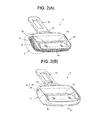
- Fig. 2(A) is a perspective view of the tongue according to an exemplary embodiment of the present invention that is used in the seat belt device according to the exemplary embodiment, the tongue being shown in a state in which molding with a hard resin has been performed and molding with a soft resin has not been performed at a grasping portion at a metallic plate, which is a core; and Fig. 2(B) is a perspective view of the tongue in a state in which molding with a soft resin has been performed on a portion of the hard resin of the tongue in the state shown in Fig. 2(A) .
- Fig. 3 is a partial enlarged sectional view along line III-III in Fig. 2(B) .
- the tongue 6 includes a securing portion 6a and a grasping portion 6b as with existing tongues.
- the securing portion 6a can be secured to the buckle 7 and the grasping portion 6b is a portion that is grasped by a seat-belt wearer when securing the securing portion 6a to the buckle 7.
- a belt through hole 6c through which the seat belt 4 passes is provided in the grasping portion 6b.
- the tongue 6 includes a metallic plate 6d and a resin molded portion 6e.
- the metallic plate 6d includes the securing portion 6a and a grasping portion corresponding section 6f corresponding to the grasping portion 6b and forms a T shape.
- the metallic plate 6d has a through hole 6t for a belt through hole 6c.
- the resin molded portion 6e is a portion where molding has been performed at the grasping portion corresponding section 6f with a resin.
- the resin molded portion 6e includes a hard-resin molded portion 6g that has been molded with a relatively hard resin and a soft-resin molded portion 6h that has been molded with a resin that is softer than the hard-resin molded portion 6g.
- polyamide resin such as nylon 6 is used for the hard-resin molded portion 6g and thermoplastic elastomer (TPE) is used for the soft-resin molded portion 6h.
- the hard-resin molded portion 6g is a portion where molding has been performed at the entire or substantially the entire surface of the grasping portion corresponding section 6f of the metallic plate 6d with polyamide resin.
- the molding with the polyamide resin is performed at an inner peripheral edge at the through hole 6t of the metallic plate 6d to form the belt through hole 6c.
- the hard-resin molded portion 6g is formed, so that the strength of the grasping portion 6b is increased.
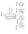
- a portion that has been molded at regions of the left side end surface and the right side end surface in Fig. 2(A) of the tongue 6 (an upper side end surface and a lower side end surface in Fig. 4(A) ; that is, side end surfaces in a direction substantially along a direction in which the securing portion 6a is secured to the buckle 7) and on a region corresponding to a side end surface opposite to the securing portion 6a and extending along an outer peripheral edge of the grasping portion 6b in Fig. 2(A) of the tongue 6 is a thin-walled portion 6i that is thinner than the other portions.
- the soft-resin molded portion 6h is a portion in which TPE molding is performed on a surface of the thin-walled portion 6i of the hard-resin molded portion 6g.
- the polyamide resin and the TPE are joined by bonding (or fusion).
- a bonding structure between the polyamide resin and the TEP is a structure in which the hard-resin molded portion 6g, formed of the polyamide resin, and the soft-resin molded portion 6h, formed of the TPE, do not easily come off from each other as a result of being firmly bonded to each other.
- the structure in which the hard-resin molded portion 6g and the soft-resin molded portion 6h do not easily come off from each other is hereunder described.
- an elongated protrusion 6j is provided at a surface of the thin-walled portion 6i of the hard-resin molded portion 6g.
- the elongated protrusion 6j extends in the thin-walled portion 6i of the hard-resin molded portion 6g along the outer peripheral edge of the grasping portion 6b to the left and right side end surfaces of the tongue 6 and the side end surface of the tongue 6 opposite to the securing portion 6a.
- An end surface 6k of the elongated protrusion 6j is formed in the form of a straight line in transverse cross section in a direction that is orthogonal to a longitudinal direction of the elongated protrusion 6j.
- the shape of the elongated protrusion 6j in the transverse cross section in the direction that is orthogonal to the longitudinal direction of the elongated protrusion 6j is formed so as to differ depending upon the position of the grasping portion 6b.
- the shape of the elongated protrusion 6j in transverse cross section is a substantially parallelogrammatic shape whose short side is substantially parallel to the metallic plate 6d.
- the soft-resin molded portion 6h is formed by TPE molding so as to cover the entire elongated protrusion 6j formed into a substantially parallelogrammatic shape in the thin-walled portion 6i of the hard-resin molded portion 6g.
- the shape of the elongated protrusion 6j in transverse cross section is substantially rectangular.
- Securing protrusions 6m and 6n are provided at sides of the substantially rectangular shape that are substantially parallel to the metallic plate 6d. These securing protrusions 6m and 6n extend in the longitudinal direction of the elongated protrusion 6j in the regions of the left and right side end surfaces, and their shapes in transverse cross section are substantially in the form of a fan forming an angle of about 90 degrees (that is, shapes that are substantially 1/4 of one circle). A portion of the arc of each fan faces a corresponding outer peripheral side end surface of the grasping portion 6b.
- the soft-resin molded portion 6h is formed by TPE molding so as to cover the entire substantially rectangular elongated protrusion 6j including the securing protrusions 6m and 6n in the thin-walled portion 6i of the hard-resin molded portion 6g.
- polyamide resins such as nylon 6
- polyamide resins such as nylon 6
- the surface of the hard-resin molded portion 6g and the surface of the soft-resin molded portion 6h are substantially flush with each other. This makes it possible to prevent a seat-belt wearer from having a strange feeling even if two different types of molded portions, that is, the hard-resin molded portion 6g and the soft-resin molded portion 6h, are provided at the grasping portion 6b of the tongue 6.
- the shape of the elongated protrusion 6j in transverse cross section is a substantially trapezoidal shape in which a side at an outer peripheral end is slightly longer.
- Securing protrusions 6m and 6n which are similar to the securing protrusions 6m and 6n shown in Fig. 4(D) , are provided at sides of the substantially trapezoidal shape that are substantially parallel to the metallic plate 6d (sides that are positioned in a direction that is substantially orthogonal to the height of the substantially trapezoidal shape).
- the soft-resin molded portion 6h is formed by TPE molding so as to cover the sides of the substantially trapezoidal shape of the substantially rectangular elongated protrusion 6j including the securing protrusions 6m and 6n in the thin-walled portion 6i of the hard-resin molded portion 6j, the sides being substantially parallel to the metallic plate 6d.
- polyamide resins such as nylon 6
- polyamide resins such as nylon 6
- the surface of the hard-resin molded portion 6g and the surface of the soft-resin molded portion 6h are substantially flush with each other. In the regions, the hard-resin molded portion 6g is exposed at part of the outer peripheral end of the grasping portion 6b and the outer peripheral end of the grasping portion 6b is formed.
- the elongated protrusion 6j causes the area of contact between the molded portions at a boundary between the hard-resin molded portion 6g and the soft-resin molded portion 6h to be larger than that at the boundary of a substantially planar shape where the elongated protrusion 6j is not provided.
- This causes the hard-resin molded portion 6g and the soft-resin molded portion 6h to be more firmly bonded (fused) with each other, as a result of which it is less likely for them to come off from each other.
- the securing protrusions 6m and 6n are provided at the side faces of the elongated protrusion 6j and form the shape of an anchor. Therefore, even if the soft-resin molded portion 6h tries to come off from the hard-resin molded portion 6g, the soft-resin molded portion 6h is secured by the securing protrusions 6m and 6n, so that an anchoring effect is provided. Consequently, it is even less likely for the soft-resin molded portion 6h to come off from the hard-resin molded portion 6g.
- the elongated protrusion 6j and the securing protrusions 6m and 6n form a structure that makes it less likely for the hard-resin molded portion 6g and the soft-resin molded portion 6h to come off from each other.
- the end surface 6k of the elongated protrusion 6j is a fine uneven surface (a surface having a predetermined surface roughness such as a knurled surface or a pear-skin surface) 6o formed by surface texturing, such as etching. Due to the fine uneven surface 6o, the polyamide resin of the hard-resin molded portion 6g and the TPE of the soft-resin molded portion 6h at the uneven surface 6o during resin molding tend to melt, so that the bonding strength (fusion strength) of the hard-resin molded portion 6g and the soft-resin molded portion 6h with each other is increased.
- the soft-resin molded portion 6h makes it possible for the soft-resin molded portion 6h to be connected to the hard-resin molded portion 6g by a planar connection that provides a predetermined bonding strength (fusion strength), as a result of which it is possible to make it even less likely for the soft-resin molded portion 6h to come off from the hard-resin molded portion 6g. Therefore, the fine uneven surface 6o also forms a structure that makes it less likely for the hard-resin molded portion 6g and the soft-resin molded portion 6h to come off from each other.
- portions 6q 1 of the ends 6q of the soft-resin molded portion 6h where the nail tips get caught are shorter than relatively long straight-line ends 6q 1 shown in Fig. 6(C) where the protruding portions 6p are not provided. That is, the protruding portions 6p reduce the sizes of areas where the nail tips get caught by the ends 6q of the soft-resin molded portion 6h.
- the protruding portions 6q also form a structure that makes it less likely for the hard-resin molded portion 6g and the soft-resin molded portion 6h to come off from each other.
- the soft-resin molded portion 6h is provided at a portion of the hard-resin molded portion 6g that tends to contact members of a vehicle body, such as a center pillar 8 (shown in Fig. 1 ), near the tongue 6. Therefore, it is possible to allow the soft-resin molded portion 6h to contact the members of the vehicle body. That is, the soft-resin molded portion 6h contacts the members of the vehicle body frequently.
- the soft-resin molded portion 6b to function as a cushioning material, it is possible to effectively reduce the occurrence of small scratches and dents in the members of the vehicle body, such as a trim, at an inside wall of a vehicle and to effectively reduce noise that is generated due to contact of the tongue 6 and the members of the vehicle body with each other.
- the elongated protrusion 6j is provided at a portion of the hard-resin molded portion 6g that is bonded or fused to the soft-resin molded portion 6h and the soft-resin molded portion 6h is molded on the elongated protrusion 6j with a soft resin so as to cover the elongated protrusion 6j. Since the elongated protrusion 6j increases the bonding area (fusion area) between the hard-resin molded portion 6g and the soft-resin molded portion 6h, it is possible to more effectively increase the bonding strength (fusion strength) between the hard-resin molded portion 6g and the soft-resin molded portion 6h.
- the hard-resin molded portion 6g is formed by performing molding at almost the entire grasping portion corresponding section 6f of the metallic plate 6d of the tongue 6 with polyamide resin. Therefore, it is possible to further increase the strength of the grasping portion 6b of the tongue 6.
- the securing protrusions 6m and 6n are provided at the respective sides of the elongated protrusion 6j of the hard-resin molded portion 6g and the soft-resin molded portion 6h is formed by TPE molding so as to cover the elongated protrusion 6j and the securing protrusions 6m and 6n.
- the securing protrusions 6m and 6n provide an anchoring effect with respect to the soft-resin molded portion 6h, so that it is possible to make it even less likely for the soft-resin molded portion 6h to come off from the hard-resin molded portion 6g.
- the securing protrusions 6m and 6n near the boundary between the soft-resin molded portion 6h and the hard-resin molded portion 6g where the soft-resin molded portion 6h tends to come off, it is possible to even more effectively reduce the coming off of the soft-resin molded portion 6h from the hard-resin molded portion 6g.
- the end surface 6k of the aforementioned elongated protrusion 6j becomes the fine uneven surface 6o by surface texturing and the soft-resin molded portion 6h is bonded or fused to the fine uneven surface 6o. Due to the fine uneven surface 6o, the polyamide resin of the hard-resin molded portion 6g and the TPE of the soft-resin molded portion 6h at the uneven surface 6o during resin molding tend to melt, so that the bonding strength (fusion strength) of the hard-resin molded portion 6g and the soft-resin molded portion 6h with each other can be increased.
- the substantially U-shaped protruding portions 6p that protrude towards the soft-resin molded portion 6h are formed at the hard-resin molded portion 6g.
- the protruding portions 6p form part of the boundary between the hard-resin molded portion 6g and the soft-resin molded portion 6h.
- the boundary region between the hard-resin molded portion 6g and the soft-resin molded portion 6h at the outer peripheral surface of the grasping portion 6b in the direction along the direction in which the securing portion 6a is secured to the buckle is a region where the tips of finger nails of a seat belt wearer tend to get caught.
- the portions 6q 1 of the ends 6q of the soft-resin molded portion 6h where the tips of the finger nails of the seat belt wearer get caught are further shortened. Therefore, since the nail tips are less likely to get caught by the ends 6q of the soft-resin molded portion 6h, it is less likely for the soft-resin molded portion 6h to come off from the hard-resin molded portion 6g.
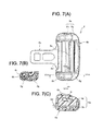
- Fig. 7(A) is a plan view of a tongue according to another exemplary embodiment of the present invention.
- Fig. 7(B) is a sectional view taken along line VIIB-VIIB in Fig. 7(A).
- Fig. 7(C) is a sectional view taken along line VIIC-VIIC in Fig. 7(A) .
- Structural portions that correspond to those of the tongue 6 according to the previous exemplary embodiment are given the same reference numerals and are not described in detail.
- a hard-resin molded portion 6g is provided by performing molding at a grasping portion corresponding section 6f of a metallic plate 6d with polyamide resin, such as nylon 6.
- a soft-resin molded portion 6h is provided on a portion of the hard-resin molded portion 6g where the tongue 6 in a seat belt device 1 that is not being used in fastening a seat belt tends to contact a vehicle body, such as a trim.
- recessed portions 6r and 6s having relatively flat bottom surfaces are formed on left and right ends (upper and lower ends in Fig. 7(A) ) of a belt through hole 6c in a region of the hard-resin molded portion 6g in a flat portion of a grasping portion 6b.
- the soft-resin molded portion 6h is provided by TPE molding in these recessed portions 6r and 6s.
- the bonding strength (fusion strength) between the hard-resin molded portion 6g and the soft-resin molded portion 6h is increased, as a result of which it is less likely for the soft-resin molded portion 6h to come off from the hard-resin molded portion 6g.
- the tongue according to the present invention can be suitably utilized as a tongue that is used in a seat belt device, that is slidably supported by a seat belt, and that is secured to a buckle fixed to, for example, a vehicle body.
- the seat belt device according to the present invention can be suitably utilized as a seat belt device using such a tongue.
Landscapes
- Automotive Seat Belt Assembly (AREA)
Description
- The present invention relates to the technical field of a tongue that is slidably supported by a seat belt and that is secured to a buckle fixed to, for example, a vehicle body and to the technical field of a seat belt device using the tongue.
- Hitherto, in a seat belt device that is attached to a seat of a vehicle, such as an automobile, an occupant is restrained by a seat belt in an emergency where a deceleration that is higher than that in a normal state acts upon a vehicle during, for example, a collision (hereunder simply referred to as "in an emergency"). As such a type of seat belt device, a three-point seat belt device is generally widely known and is frequently used. In a general three-point seat belt device that is well known, a seat belt that has been withdrawn from a seat belt retractor is guided by a belt guide anchor and its front end is fixed to a vehicle body. A tongue is slidably supported by the seat belt that has been guided by the belt guide anchor. In this case, the seat belt slidably passes through an elongated seat-belt through hole of the tongue. By securing the tongue to a buckle fixed to the vehicle body, the seat belt is fastened around the occupant.
- When a seat belt is not fastened, since, ordinarily, the seat belt is maximally retracted by the seat-belt retractor, the seat belt is positioned along an inside wall of a vehicle at, for example, a center pillar. Therefore, the tongue positioned by a tongue stopper is positioned near this inside wall. Consequently, if, when an occupant gets off the vehicle, the occupant contacts the tongue, the tongue may contact a trim at the inside wall of the vehicle. When, in order to get off the vehicle, the occupant wearing the seat belt detaches the tongue from the buckle and lets go of the tongue, the seat belt is retracted by the seat belt retractor. During the retraction of the seat belt, the tongue may similarly contact the trim at the inside wall of the vehicle as a result of being raised as the seat belt is being retracted. Further, the tongue of the seat belt device in a state in which an occupant is not seated on a seat of the vehicle and in which the seat belt is in an unfastened state may similarly contact the trim at the inside wall of the vehicle due to vibration generated when the vehicle travels. In this case, since the tongue is guided so that a securing portion faces the inside of a vehicle chamber by the tongue stopper, a portion that contacts the trim at the inside wall of the vehicle is mostly a grasping portion. When the tongue contacts the trim at the inside wall of the vehicle in this way, not only may abnormal noise be generated, but also small scratches or dents may occur in the trim. This may cause the inside of the vehicle chamber to be unpleasant.
- Accordingly, in order to prevent the occurrence of such abnormal noise and such small scratches or dents, the following tongue is proposed. The tongue is such that, at a grasping portion of the tongue that is very likely to contact a trim at an inside wall of a vehicle, molding with a relatively hard resin is performed at a portion of a metallic plate that becomes a core and through which a seat belt passes and molding with a resin that is softer than the hard resin is performed at a portion of the metallic plate that is very likely to contact the inside wall of the vehicle (refer to, for example, Patent Literature (PTL) 1).
- According to the tongue described in
PTL 1, by performing molding with a hard resin at a portion of an end surface of a soft-resin molded portion so as to cover the portion of the end surface of the soft-resin molded portion, it is possible to firmly maintain close contact between the core of the metallic plate and a tip edge of the end surface of the soft-resin molded portion, and to prevent the tip edge of the end surface of the soft-resin molded portion from coming off from the core. - PTL 1: Japanese Unexamined Patent Application Publication No.
2007-229350 - Hitherto, polyamide resin, such as
nylon 6, is used for performing molding at the metallic plate with a hard resin, and thermoplastic elastomer (TPE) is often used for performing molding at the metallic plate with a soft resin. - However, it is difficult to bond (or fuse) the polyamide resin, such as
nylon 6, and the thermoplastic elastomer (TPE) to each other due to problems related to differences between the molding temperatures and physical properties of these materials. Therefore, these two resins tend to come off from each other. Consequently, there is room for further considering durability. Accordingly, as in the tongue described in theaforementioned PTL 1, by covering the end surface of the polyamide-resin molded portion using thermoplastic elastomer (TPE), it is possible to prevent the tip edge of the end surface of the soft-resin molded portion from coming off from the core. However, it is difficult to bond (fuse) the thermoplastic elastomer (TPE) and the polyamide-resin molded portion to each other. Therefore, firmer bonding (fusion) between the thermoplastic elastomer (TPE) and the polyamide-resin molded portion is required. - The present invention has been achieved in view of such circumstances, and its object is to provide a tongue that is capable of further increasing durability by reducing coming off of two different resins of a resin molded portion at a metallic plate, while reducing the occurrence of small scratches or dents in a surrounding member and reducing abnormal noise when the tongue contacts this member. Solution to Problem
- To solve the aforementioned problem, there is provided a tongue according to the present invention including a securing portion that is formed of a metallic plate and that is securable to a buckle and a resin molded portion that forms a grasping portion as a result of performing molding at a grasping portion corresponding section with a resin and that has a belt through hole through which a seat belt passes, the grasping portion corresponding section being formed of the metallic plate and being integrally formed with the securing portion, the grasping portion being grasped and a securing operation being performed to secure the securing portion to the buckle, wherein the resin molded portion includes a hard-resin molded portion that is formed by performing molding at a predetermined portion of the grasping portion corresponding section of the metallic plate with a hard resin and a soft-resin molded portion that is formed by being molded on a predetermined portion of the hard-resin molded portion with a resin that is softer than the hard resin and by being bonded or fused to the hard-resin molded portion, wherein an elongated protrusion is provided at a portion where the hard-resin molded portion is bonded or fused to the soft-resin molded portion, and wherein the soft-resin molded portion is molded with the soft resin so as to cover the elongated protrusion.
- In addition, according to the tongue of the present invention, two securing protrusions are provided at respective side surfaces of the elongated protrusion and the soft-resin molded portion is molded with the soft resin so as to cover the securing protrusions, and the securing protrusions are securing protrusions that reduce coming off of the soft-resin molded portion from the hard-resin molded portion.
- Further, according to the tongue of the present invention, an end surface of the elongated protrusion of the hard-resin molded portion is a fine uneven surface, and the soft-resin molded portion is bonded or fused to the fine uneven surface.
- Further, according to the tongue of the present invention, a protruding portion that protrudes towards the soft-resin molded portion is provided at an end of the hard-resin molded portion at an outer peripheral surface of the grasping portion in a direction along a direction in which the securing portion is secured to the buckle, and the protruding portion forms part of a boundary between the hard-resin molded portion and the soft-resin molded portion.
- A seat belt device according to the present invention includes at least a seat belt, a seat belt retractor that retracts the seat belt, a tongue that is slidably supported by the seat belt, and a buckle, the tongue being inserted into and secured to the buckle, the seat belt being fastened around an occupant by inserting the tongue into and securing the tongue by the buckle, wherein the tongue is the tongue according to any one of the above-described tongues according to the present invention.
- According to the tongue and the seat belt device of the present invention having such structures, the soft-resin molded portion is bonded or fused to a predetermined portion of the hard-resin molded portion. Therefore, by providing the soft-resin molded portion at a portion of the hard-resin molded portion that tends to contact members of a vehicle body, such as a center pillar, near the tongue, it is possible to allow the soft-resin molded portion to contact the members of the vehicle body. Consequently, by causing the soft-resin molded portion to function as a cushioning material, it is possible to effectively reduce the occurrence of small scratches and dents in the members of the vehicle body, and to effectively reduce noise that is generated due to contact of the tongue and the members of the vehicle body with each other.
- In addition, an elongated protrusion is provided at a portion of the hard-resin molded portion that is bonded or fused to the soft-resin molded portion and the soft-resin molded portion is molded at the elongated protrusion with a soft resin so as to cover the elongated protrusion. Since the elongated protrusion increases the bonding area (fusion area) between the hard-resin molded portion and the soft-resin molded portion, it is possible to more effectively increase the bonding strength (fusion strength) between the hard-resin molded portion and the soft-resin molded portion. Consequently, even if two different types of mold resins are used, it is possible to provide a structure in which the soft-resin molded portion is less likely to come off from the hard-resin molded portion due to the elongated protrusion, as a result of which the coming off of the soft-resin molded portion from the hard-resin molded portion is reduced. Thus, it is possible to further increase the durability of the resin molded portion of the tongue (that is, the durability of the grasping portion of the tongue).
- Further, the hard-resin molded portion is formed by performing molding at almost the entire grasping portion corresponding section of the metallic plate of the tongue with a relatively hard resin, such as polyamide resin, so that it is possible to further increase the strength of the grasping portion of the tongue.
- Further, two securing protrusions are provided at respective sides of the elongated protrusion and the soft-resin molded portion is molded on the securing protrusions with a soft resin so as to cover the securing protrusions. Since the securing protrusions provide an anchoring effect with respect to the soft-resin molded portion, it is possible to make it even less likely for the soft-resin molded portion to come off from the hard-resin molded portion. In particular, by providing the securing protrusions near the boundary between the soft-resin molded portion and the hard-resin molded portion where the soft-resin molded portion tends to come off, it is possible to even more effectively reduce the coming off of the soft-resin molded portion from the hard-resin molded portion.
- Further, since the end surface of the elongated protrusion of the hard-resin molded portion is formed as a fine uneven surface and the soft-resin molded portion is bonded or fused to the fine uneven surface, the relatively hard resin of the hard-resin molded portion and the relatively soft resin of the soft-resin molded portion at the uneven surface during resin molding tend to melt, so that the bonding strength (fusion strength) between the hard-resin molded portion and the soft-resin molded portion can be considerably increased. This makes it possible for the soft-resin molded portion to be connected to the hard-resin molded portion by a planar connection that provides a predetermined bonding strength (fusion strength), as a result of which it is possible to make it even less likely for the soft-resin molded portion to come off from the hard-resin molded portion.
- Further, a protruding portion that protrudes towards the soft-resin molded portion is provided at the end of the hard-resin molded portion at the outer peripheral surface of the grasping portion in the direction along the direction in which the securing portion is secured to the buckle, and the protruding portion forms part of a boundary between the hard-resin molded portion and the soft-resin molded portion. The boundary region between the hard-resin molded portion and the soft-resin molded portion at the outer peripheral surface of the grasping portion in the direction along the direction in which the securing portion is secured to the buckle is a region where the tips of finger nails of a seat belt wearer tend to get caught. However, this protruding portion allows the portion of the end of the soft-resin molded portion where the tips of the finger nails of the seat belt wearer get caught to be further shortened. Therefore, since the tips of the finger nails are less likely to get caught by the end of the soft-resin molded portion, it is less likely for the soft-resin molded portion to come off from the hard-resin molded portion.
-
- [
Fig. 1] Fig. 1 is a schematic view of a seat belt device according to an exemplary embodiment of the present invention. - [
Fig. 2] Fig. 2(A) is a perspective view of a tongue according to an exemplary embodiment of the present invention that is used in the seat belt device according to the exemplary embodiment, the tongue being shown in a state in which molding with a hard resin has been performed and molding with a soft resin has not been performed at a grasping portion at a metallic plate, which is a core; andFig. 2(B) is a perspective view of the tongue in a state in which molding with a soft resin has been performed on a portion of the hard resin of the tongue in the state shown inFig. 2(A) . - [
Fig. 3] Fig. 3 is a partial enlarged sectional view along line III-III inFig. 2(B) . - [
Fig. 4] Fig. 4(A) is a plan view of the tongue according to the exemplary embodiment shown inFig. 2(B) ,Fig. 4(B) is a sectional view taken along line IVB-IVB inFig. 4(A), Fig. 4(C) is a sectional view taken along line IVC-IVC inFig. 4(A), Fig. 4(D) is a sectional view taken along line IVD-IVD inFig. 4(A), and Fig. 4(E) is a sectional view taken along line IVE-IVE inFig. 4(A) . - [
Fig. 5] Fig. 5 is a partial enlarged perspective view of a portion V inFig. 2(A) . - [
Fig. 6] Fig. 6 is a front view ofFig. 4(A) of the tongue according to the exemplary embodiment shown inFig. 4(A) . - [
Fig. 7] Fig. 7(A) is a plan view of a tongue according to another exemplary embodiment of the present invention,Fig. 7(B) is a sectional view taken along line VIIB-VIIB inFig. 7(A), and Fig. 7(C) is a sectional view taken along line VIIC-VIIC inFig. 7(A) . - Exemplary embodiments of the present invention are hereunder described using the drawings.
-
Fig. 1 is a schematic view of a seat belt device according to an exemplary embodiment of the present invention. - As shown in
Fig. 1 , the seat belt device according to the exemplary embodiment is basically the same as a three-point seat belt device that is generally publicly known. InFig. 1 ,reference numeral 1 denotes the seat belt device,reference numeral 2 denotes a vehicle seat, reference numeral 3 denotes a seat belt retractor disposed at a vehicle body near thevehicle seat 2,reference numeral 4 denotes a seat belt that is withdrawably retracted by the seat belt retractor 3 and whose belt anchor 4a provided at an end of theseat belt 4 is fixed to a floor of the vehicle body or thevehicle seat 2,reference numeral 5 denotes a belt guide anchor that guides theseat belt 4 withdrawn from the seat belt retractor 3 towards an occupant's shoulder,reference numeral 6 denotes a tongue that is slidably supported by theseat belt 4 guided from thebelt guide anchor 5, andreference numeral 7 denotes a buckle that is fixed to the floor of the vehicle body or thevehicle seat 2, thetongue 6 being inserted into and secured to thebuckle 7 so as to be engageable with and disengageable from thebuckle 7. A fastening operation and an unfastening operation of theseat belt 4 of theseat belt device 1 are also the same as those of existing seat belt devices that are publicly known. - When the seat belt 3 is not fastened, the
tongue 6 is not secured to thebuckle 7 and the whole seal belt 4 (more specifically, the length of theseat belt 4 that can be retracted by the seat belt retractor 3 without a problem) is retracted by the seat belt retractor 3. When theseat belt 4 is fastened around an occupant, as shown inFig. 1 , theseat belt 4 is withdrawn from the seat belt retractor 3 by a predetermined length. In addition, by securing thetongue 6 to thebuckle 7 and removing slack in theseat belt 4, theseat belt 4 is fastened around the occupant. -
Fig. 2(A) is a perspective view of the tongue according to an exemplary embodiment of the present invention that is used in the seat belt device according to the exemplary embodiment, the tongue being shown in a state in which molding with a hard resin has been performed and molding with a soft resin has not been performed at a grasping portion at a metallic plate, which is a core; andFig. 2(B) is a perspective view of the tongue in a state in which molding with a soft resin has been performed on a portion of the hard resin of the tongue in the state shown inFig. 2(A) .Fig. 3 is a partial enlarged sectional view along line III-III inFig. 2(B) . - As shown in
Figs. 2(A) and 2(B) andFig. 3 , thetongue 6 according to the exemplary embodiment includes a securingportion 6a and a graspingportion 6b as with existing tongues. In this case, the securingportion 6a can be secured to thebuckle 7 and the graspingportion 6b is a portion that is grasped by a seat-belt wearer when securing the securingportion 6a to thebuckle 7. A belt throughhole 6c through which theseat belt 4 passes is provided in the graspingportion 6b. - In addition, the
tongue 6 includes ametallic plate 6d and a resin moldedportion 6e. Themetallic plate 6d includes the securingportion 6a and a graspingportion corresponding section 6f corresponding to the graspingportion 6b and forms a T shape. Themetallic plate 6d has a throughhole 6t for a belt throughhole 6c. The resin moldedportion 6e is a portion where molding has been performed at the graspingportion corresponding section 6f with a resin. In this case, the resin moldedportion 6e includes a hard-resin moldedportion 6g that has been molded with a relatively hard resin and a soft-resin moldedportion 6h that has been molded with a resin that is softer than the hard-resin moldedportion 6g. For example, polyamide resin, such asnylon 6, is used for the hard-resin moldedportion 6g and thermoplastic elastomer (TPE) is used for the soft-resin moldedportion 6h. - As shown in
Figs. 2(A) ,3 , and4(A) , the hard-resin moldedportion 6g is a portion where molding has been performed at the entire or substantially the entire surface of the graspingportion corresponding section 6f of themetallic plate 6d with polyamide resin. In this case, the molding with the polyamide resin is performed at an inner peripheral edge at the throughhole 6t of themetallic plate 6d to form the belt throughhole 6c. In this way, when the molding with the polyamide resin is performed at the entire or substantially the entire surface of the graspingportion corresponding section 6f of themetallic plate 6d, the hard-resin moldedportion 6g is formed, so that the strength of the graspingportion 6b is increased. In the hard-resin moldedportion 6g, a portion that has been molded at regions of the left side end surface and the right side end surface inFig. 2(A) of the tongue 6 (an upper side end surface and a lower side end surface inFig. 4(A) ; that is, side end surfaces in a direction substantially along a direction in which the securingportion 6a is secured to the buckle 7) and on a region corresponding to a side end surface opposite to the securingportion 6a and extending along an outer peripheral edge of the graspingportion 6b inFig. 2(A) of thetongue 6 is a thin-walled portion 6i that is thinner than the other portions. Two ends of the thin-walled portion 6i are positioned substantially at securing-portion-6a side ends at respective left and right side end surfaces of thetongue 6. The soft-resin moldedportion 6h is a portion in which TPE molding is performed on a surface of the thin-walled portion 6i of the hard-resin moldedportion 6g. In this case, the polyamide resin and the TPE are joined by bonding (or fusion). - As mentioned above, in general, it is difficult to firmly bond polyamide resin and TPE, and they relatively easily come off from each other. Accordingly, in the
tongue 6 according to the exemplary embodiment, a bonding structure between the polyamide resin and the TEP is a structure in which the hard-resin moldedportion 6g, formed of the polyamide resin, and the soft-resin moldedportion 6h, formed of the TPE, do not easily come off from each other as a result of being firmly bonded to each other. The structure in which the hard-resin moldedportion 6g and the soft-resin moldedportion 6h do not easily come off from each other is hereunder described. - As shown in
Figs. 2(A) ,3 , and4(B) to 4(E) , first, anelongated protrusion 6j is provided at a surface of the thin-walled portion 6i of the hard-resin moldedportion 6g. In this case, as a substantially U-shaped rib, theelongated protrusion 6j extends in the thin-walled portion 6i of the hard-resin moldedportion 6g along the outer peripheral edge of the graspingportion 6b to the left and right side end surfaces of thetongue 6 and the side end surface of thetongue 6 opposite to the securingportion 6a. Anend surface 6k of theelongated protrusion 6j is formed in the form of a straight line in transverse cross section in a direction that is orthogonal to a longitudinal direction of theelongated protrusion 6j. The shape of theelongated protrusion 6j in the transverse cross section in the direction that is orthogonal to the longitudinal direction of theelongated protrusion 6j is formed so as to differ depending upon the position of the graspingportion 6b. - That is, as shown in
Fig. 3 andFigs. 4(B) and 4(C) , in the region of the side end surface opposite to the securingportion 6a and regions of corners between the side end surface opposite to the securingportion 6a of thetongue 6 and the left and right side end surfaces of thetongue 6, the shape of theelongated protrusion 6j in transverse cross section is a substantially parallelogrammatic shape whose short side is substantially parallel to themetallic plate 6d. The soft-resin moldedportion 6h is formed by TPE molding so as to cover the entireelongated protrusion 6j formed into a substantially parallelogrammatic shape in the thin-walled portion 6i of the hard-resin moldedportion 6g. In this case, by increasing the molding temperature during the TPE molding, polyamide resins (such as nylon 6) at twoedge portions elongated protrusion 6j are fused, so that the polyamide resins (such as nylon 6) and the TPE are more firmly bonded (fused) with each other. The surface of the hard-resin moldedportion 6g and the surface of the soft-resin moldedportion 6h are substantially flush with each other. This makes it possible to prevent a seat-belt wearer from having a strange feeling even if two different types of molded portions, that is, the hard-resin moldedportion 6g and the soft-resin moldedportion 6h are provided at the graspingportion 6b of thetongue 6. - As shown in
Fig. 4(D) , in the regions of the left and right side end surfaces of thetongue 6, the shape of theelongated protrusion 6j in transverse cross section is substantially rectangular. Securingprotrusions metallic plate 6d. These securingprotrusions elongated protrusion 6j in the regions of the left and right side end surfaces, and their shapes in transverse cross section are substantially in the form of a fan forming an angle of about 90 degrees (that is, shapes that are substantially 1/4 of one circle). A portion of the arc of each fan faces a corresponding outer peripheral side end surface of the graspingportion 6b. The soft-resin moldedportion 6h is formed by TPE molding so as to cover the entire substantially rectangularelongated protrusion 6j including the securingprotrusions walled portion 6i of the hard-resin moldedportion 6g. In this case, similarly to the above, by increasing the molding temperature during the TPE molding, polyamide resins (such as nylon 6) at twoedge portions protrusions portion 6g and the surface of the soft-resin moldedportion 6h are substantially flush with each other. This makes it possible to prevent a seat-belt wearer from having a strange feeling even if two different types of molded portions, that is, the hard-resin moldedportion 6g and the soft-resin moldedportion 6h, are provided at the graspingportion 6b of thetongue 6. - Further, as shown in
Fig. 4(E) , in the regions of the two ends of the thin-walled portion 6i at the left and right side end surfaces of thetongue 6, the shape of theelongated protrusion 6j in transverse cross section is a substantially trapezoidal shape in which a side at an outer peripheral end is slightly longer. Securingprotrusions protrusions Fig. 4(D) , are provided at sides of the substantially trapezoidal shape that are substantially parallel to themetallic plate 6d (sides that are positioned in a direction that is substantially orthogonal to the height of the substantially trapezoidal shape). The soft-resin moldedportion 6h is formed by TPE molding so as to cover the sides of the substantially trapezoidal shape of the substantially rectangularelongated protrusion 6j including the securingprotrusions walled portion 6i of the hard-resin moldedportion 6j, the sides being substantially parallel to themetallic plate 6d. In this case, similarly to the above, by increasing the molding temperature during the TPE molding, polyamide resins (such as nylon 6) at twoedge portions protrusions portion 6g and the surface of the soft-resin moldedportion 6h are substantially flush with each other. In the regions, the hard-resin moldedportion 6g is exposed at part of the outer peripheral end of the graspingportion 6b and the outer peripheral end of the graspingportion 6b is formed. - In this way, in the regions of the left and right side end surfaces of the
tongue 6, theelongated protrusion 6j causes the area of contact between the molded portions at a boundary between the hard-resin moldedportion 6g and the soft-resin moldedportion 6h to be larger than that at the boundary of a substantially planar shape where theelongated protrusion 6j is not provided. This causes the hard-resin moldedportion 6g and the soft-resin moldedportion 6h to be more firmly bonded (fused) with each other, as a result of which it is less likely for them to come off from each other. - In particular, in the regions at the left and right side end surfaces of the
tongue 6, the securingprotrusions elongated protrusion 6j and form the shape of an anchor. Therefore, even if the soft-resin moldedportion 6h tries to come off from the hard-resin moldedportion 6g, the soft-resin moldedportion 6h is secured by the securingprotrusions portion 6h to come off from the hard-resin moldedportion 6g. Accordingly, theelongated protrusion 6j and the securingprotrusions portion 6g and the soft-resin moldedportion 6h to come off from each other. - Further, as shown in
Fig. 5 , theend surface 6k of theelongated protrusion 6j is a fine uneven surface (a surface having a predetermined surface roughness such as a knurled surface or a pear-skin surface) 6o formed by surface texturing, such as etching. Due to the fine uneven surface 6o, the polyamide resin of the hard-resin moldedportion 6g and the TPE of the soft-resin moldedportion 6h at the uneven surface 6o during resin molding tend to melt, so that the bonding strength (fusion strength) of the hard-resin moldedportion 6g and the soft-resin moldedportion 6h with each other is increased. This makes it possible for the soft-resin moldedportion 6h to be connected to the hard-resin moldedportion 6g by a planar connection that provides a predetermined bonding strength (fusion strength), as a result of which it is possible to make it even less likely for the soft-resin moldedportion 6h to come off from the hard-resin moldedportion 6g. Therefore, the fine uneven surface 6o also forms a structure that makes it less likely for the hard-resin moldedportion 6g and the soft-resin moldedportion 6h to come off from each other. - Further, as shown in
Figs. 6(A) and 6(B) , in the regions of the left and right side end surfaces of thetongue 6, substantially U-shaped protrudingportions 6p that protrude towards the soft-resin moldedportion 6 are formed at the hard-resin moldedportion 6g. Ends 6q of the soft-resin moldedportion 6h at the boundary between the hard-resin moldedportion 6g and the soft-resin moldedportion 6h in the regions of the left and right side end surfaces of thetongue 6 get caught by nail tips of fingers of a person handling the tongue, such as a seat belt wearer, as a result of which the soft-resin moldedportion 6h tends to come off. Therefore, by providing the protrudingportions 6p,portions 6q1 of theends 6q of the soft-resin moldedportion 6h where the nail tips get caught (straight-line portions excluding the protrudingportions 6p) are shorter than relatively long straight-line ends 6q1 shown inFig. 6(C) where the protrudingportions 6p are not provided. That is, the protrudingportions 6p reduce the sizes of areas where the nail tips get caught by theends 6q of the soft-resin moldedportion 6h. This makes it less likely for the nail tips to get caught by theends 6q of the soft-resin moldedportion 6h, as a result of which it becomes less likely for the soft-resin moldedportion 6h to come off from the hard-resin moldedportion 6g. Therefore, the protrudingportions 6q also form a structure that makes it less likely for the hard-resin moldedportion 6g and the soft-resin moldedportion 6h to come off from each other. - According to the
tongue 6 of the exemplary embodiment and theseat belt device 1 of the exemplary embodiment, by providing the soft-resin moldedportion 6h at the left and right end portions of the graspingportion 6b of thetongue 6 and the end portion of the graspingportion 6b of thetongue 6 opposite to the securingportion 6a, the soft-resin moldedportion 6b is provided at a portion of the hard-resin moldedportion 6g that tends to contact members of a vehicle body, such as a center pillar 8 (shown inFig. 1 ), near thetongue 6. Therefore, it is possible to allow the soft-resin moldedportion 6h to contact the members of the vehicle body. That is, the soft-resin moldedportion 6h contacts the members of the vehicle body frequently. Consequently, by causing the soft-resin moldedportion 6b to function as a cushioning material, it is possible to effectively reduce the occurrence of small scratches and dents in the members of the vehicle body, such as a trim, at an inside wall of a vehicle and to effectively reduce noise that is generated due to contact of thetongue 6 and the members of the vehicle body with each other. - In addition, the
elongated protrusion 6j is provided at a portion of the hard-resin moldedportion 6g that is bonded or fused to the soft-resin moldedportion 6h and the soft-resin moldedportion 6h is molded on theelongated protrusion 6j with a soft resin so as to cover theelongated protrusion 6j. Since theelongated protrusion 6j increases the bonding area (fusion area) between the hard-resin moldedportion 6g and the soft-resin moldedportion 6h, it is possible to more effectively increase the bonding strength (fusion strength) between the hard-resin moldedportion 6g and the soft-resin moldedportion 6h. Consequently, even if two different types of mold resins are used, it is possible to provide a structure in which the soft-resin moldedportion 6h is less likely to come off from the hard-resin moldedportion 6g due to theelongated protrusion 6j, as a result of which the coming off of the soft-resin moldedportion 6h from the hard-resin moldedportion 6g is reduced. Thus, it is possible to further increase the durability of the resin moldedportion 6e of the tongue 6 (that is, the durability of the graspingportion 6b of the tongue 6). - Further, the hard-resin molded
portion 6g is formed by performing molding at almost the entire graspingportion corresponding section 6f of themetallic plate 6d of thetongue 6 with polyamide resin. Therefore, it is possible to further increase the strength of the graspingportion 6b of thetongue 6. - Further, in the regions of the left and right side end surfaces of the
tongue 6, the securingprotrusions elongated protrusion 6j of the hard-resin moldedportion 6g and the soft-resin moldedportion 6h is formed by TPE molding so as to cover theelongated protrusion 6j and the securingprotrusions tongue 6, the securingprotrusions portion 6h, so that it is possible to make it even less likely for the soft-resin moldedportion 6h to come off from the hard-resin moldedportion 6g. In particular, by providing the securingprotrusions portion 6h and the hard-resin moldedportion 6g where the soft-resin moldedportion 6h tends to come off, it is possible to even more effectively reduce the coming off of the soft-resin moldedportion 6h from the hard-resin moldedportion 6g. - Further, the
end surface 6k of the aforementionedelongated protrusion 6j becomes the fine uneven surface 6o by surface texturing and the soft-resin moldedportion 6h is bonded or fused to the fine uneven surface 6o. Due to the fine uneven surface 6o, the polyamide resin of the hard-resin moldedportion 6g and the TPE of the soft-resin moldedportion 6h at the uneven surface 6o during resin molding tend to melt, so that the bonding strength (fusion strength) of the hard-resin moldedportion 6g and the soft-resin moldedportion 6h with each other can be increased. This makes it possible for the soft-resin moldedportion 6h to be connected to the hard-resin moldedportion 6g by a planar connection that provides a predetermined bonding strength (fusion strength), as a result of which it is possible to make it even less likely for the soft-resin moldedportion 6h to come off from the hard-resin moldedportion 6g. - Further, in the regions of the left and right side end surfaces of the
tongue 6, the substantially U-shaped protrudingportions 6p that protrude towards the soft-resin moldedportion 6h are formed at the hard-resin moldedportion 6g. The protrudingportions 6p form part of the boundary between the hard-resin moldedportion 6g and the soft-resin moldedportion 6h. The boundary region between the hard-resin moldedportion 6g and the soft-resin moldedportion 6h at the outer peripheral surface of the graspingportion 6b in the direction along the direction in which the securingportion 6a is secured to the buckle is a region where the tips of finger nails of a seat belt wearer tend to get caught. Therefore, by providing the protrudingportions 6p, theportions 6q1 of theends 6q of the soft-resin moldedportion 6h where the tips of the finger nails of the seat belt wearer get caught (straight-line portions excluding the protrudingportions 6p) are further shortened. Therefore, since the nail tips are less likely to get caught by theends 6q of the soft-resin moldedportion 6h, it is less likely for the soft-resin moldedportion 6h to come off from the hard-resin moldedportion 6g. -
Fig. 7(A) is a plan view of a tongue according to another exemplary embodiment of the present invention.Fig. 7(B) is a sectional view taken along line VIIB-VIIB inFig. 7(A). Fig. 7(C) is a sectional view taken along line VIIC-VIIC inFig. 7(A) . Structural portions that correspond to those of thetongue 6 according to the previous exemplary embodiment are given the same reference numerals and are not described in detail. - As shown in
Figs. 7(A) to 7(C) , in thetongue 6 according to the other exemplary embodiment, as in the previous exemplary embodiment, a hard-resin moldedportion 6g is provided by performing molding at a graspingportion corresponding section 6f of ametallic plate 6d with polyamide resin, such asnylon 6. In addition, in thetongue 6 according to this exemplary embodiment, a soft-resin moldedportion 6h is provided on a portion of the hard-resin moldedportion 6g where thetongue 6 in aseat belt device 1 that is not being used in fastening a seat belt tends to contact a vehicle body, such as a trim. More specifically, recessedportions 6r and 6s having relatively flat bottom surfaces are formed on left and right ends (upper and lower ends inFig. 7(A) ) of a belt throughhole 6c in a region of the hard-resin moldedportion 6g in a flat portion of a graspingportion 6b. In addition, the soft-resin moldedportion 6h is provided by TPE molding in these recessedportions 6r and 6s. In this case, as in the previous exemplary embodiment, by forming a fine uneven surface 6o by surface-texturing the substantially flat bottom surfaces of the recessedportions 6r and 6s, the bonding strength (fusion strength) between the hard-resin moldedportion 6g and the soft-resin moldedportion 6h is increased, as a result of which it is less likely for the soft-resin moldedportion 6h to come off from the hard-resin moldedportion 6g. - The other structural features and operational advantages of the
tongue 6 according to this exemplary embodiment are the same as those of thetongue 6 according to the previous exemplary embodiment. - The present invention is not limited to the above-described exemplary embodiments, so that various changes in design may be made within the technical matters in the scope of the claims.
- The tongue according to the present invention can be suitably utilized as a tongue that is used in a seat belt device, that is slidably supported by a seat belt, and that is secured to a buckle fixed to, for example, a vehicle body. In addition, the seat belt device according to the present invention can be suitably utilized as a seat belt device using such a tongue.
Claims (5)
- A tongue comprising a securing portion that is formed of a metallic plate and that is securable to a buckle and a resin molded portion that forms a grasping portion as a result of performing molding at a grasping portion corresponding section with a resin and that has a belt through hole through which a seat belt passes, the grasping portion corresponding section being formed of the metallic plate and being integrally formed with the securing portion, the grasping portion being grasped and a securing operation being performed to secure the securing portion to the buckle,
wherein the resin molded portion includes a hard-resin molded portion that is formed by performing molding at a predetermined portion of the grasping portion corresponding section of the metallic plate with a hard resin and a soft-resin molded portion that is formed by being molded on a predetermined portion of the hard-resin molded portion with a resin that is softer than the hard resin and by being bonded or fused to the hard-resin molded portion,
wherein an elongated protrusion is provided at a portion where the hard-resin molded portion is bonded or fused to the soft-resin molded portion, and
wherein the soft-resin molded portion is molded with the soft resin so as to cover the elongated protrusion. - The tongue according to Claim 1, wherein two securing protrusions are provided at respective side surfaces of the elongated protrusion, and
wherein the soft-resin molded portion is molded with the soft resin so as to cover the securing protrusions and the securing protrusions are securing protrusions that reduce coming off of the soft-resin molded portion from the hard-resin molded portion. - The tongue according to either Claim 1 or Claim 2, wherein an end surface of the elongated protrusion of the hard-resin molded portion is a fine uneven surface, and
wherein the soft-resin molded portion is bonded or fused to the fine uneven surface. - The tongue according to any one of Claims 1 to 3, wherein a protruding portion that protrudes towards the soft-resin molded portion is provided at an end of the hard-resin molded portion at an outer peripheral surface of the grasping portion in a direction along a direction in which the securing portion is secured to the buckle, and
wherein the protruding portion forms part of a boundary between the hard-resin molded portion and the soft-resin molded portion. - A seat belt device comprising at least a seat belt, a seat belt retractor that retracts the seat belt, a tongue that is slidably supported by the seat belt, and a buckle, the tongue being inserted into and secured to the buckle, the seat belt being fastened around an occupant by inserting the tongue into and securing the tongue to the buckle,
wherein the tongue is the tongue according to any one of Claims 1 to 4.
Applications Claiming Priority (2)
| Application Number | Priority Date | Filing Date | Title |
|---|---|---|---|
| JP2013017073A JP6041435B2 (en) | 2013-01-31 | 2013-01-31 | Tongue and seat belt device using the same |
| PCT/JP2013/084425 WO2014119183A1 (en) | 2013-01-31 | 2013-12-24 | Tongue and seat belt device using same |
Publications (3)
| Publication Number | Publication Date |
|---|---|
| EP2952395A1 true EP2952395A1 (en) | 2015-12-09 |
| EP2952395A4 EP2952395A4 (en) | 2016-07-06 |
| EP2952395B1 EP2952395B1 (en) | 2017-08-02 |
Family
ID=51261907
Family Applications (1)
| Application Number | Title | Priority Date | Filing Date |
|---|---|---|---|
| EP13873342.3A Not-in-force EP2952395B1 (en) | 2013-01-31 | 2013-12-24 | Tongue and seat belt device using same |
Country Status (3)
| Country | Link |
|---|---|
| EP (1) | EP2952395B1 (en) |
| JP (1) | JP6041435B2 (en) |
| WO (1) | WO2014119183A1 (en) |
Cited By (2)
| Publication number | Priority date | Publication date | Assignee | Title |
|---|---|---|---|---|
| CN108652141A (en) * | 2017-03-27 | 2018-10-16 | 株式会社东海理化电机制作所 | Seat safety belt apparatus tongue piece |
| US10512310B2 (en) | 2018-02-05 | 2019-12-24 | Autoliv Asp, Inc. | Noise dampening tongues for use in a seat belt restraining system and methods of making the same |
Family Cites Families (8)
| Publication number | Priority date | Publication date | Assignee | Title |
|---|---|---|---|---|
| JP2001080459A (en) * | 1999-09-09 | 2001-03-27 | Nsk Ltd | Seat belt equipment |
| JP4233188B2 (en) * | 1999-11-19 | 2009-03-04 | オートリブ株式会社 | Seat belt device |
| US6837519B2 (en) * | 2002-06-21 | 2005-01-04 | General Motors Corporation | Seat belt latch plate and method of making same |
| JP4197140B2 (en) * | 2003-06-19 | 2008-12-17 | パナソニック株式会社 | Semiconductor device |
| JP4807878B2 (en) * | 2006-03-03 | 2011-11-02 | タカタ株式会社 | Tongue and seat belt device using the same |
| JP5238193B2 (en) * | 2007-06-26 | 2013-07-17 | 株式会社遠州 | Tongue and manufacturing method thereof |
| JP2009113532A (en) * | 2007-11-02 | 2009-05-28 | Takata Corp | Tongue and seat belt device equipped with the same |
| JP2012054323A (en) * | 2010-08-31 | 2012-03-15 | Sumitomo Bakelite Co Ltd | Prepreg, substrate and semiconductor device |
-
2013
- 2013-01-31 JP JP2013017073A patent/JP6041435B2/en not_active Expired - Fee Related
- 2013-12-24 EP EP13873342.3A patent/EP2952395B1/en not_active Not-in-force
- 2013-12-24 WO PCT/JP2013/084425 patent/WO2014119183A1/en not_active Ceased
Cited By (3)
| Publication number | Priority date | Publication date | Assignee | Title |
|---|---|---|---|---|
| CN108652141A (en) * | 2017-03-27 | 2018-10-16 | 株式会社东海理化电机制作所 | Seat safety belt apparatus tongue piece |
| CN108652141B (en) * | 2017-03-27 | 2020-12-15 | 株式会社东海理化电机制作所 | Tongue piece for seat belt device |
| US10512310B2 (en) | 2018-02-05 | 2019-12-24 | Autoliv Asp, Inc. | Noise dampening tongues for use in a seat belt restraining system and methods of making the same |
Also Published As
| Publication number | Publication date |
|---|---|
| EP2952395B1 (en) | 2017-08-02 |
| WO2014119183A1 (en) | 2014-08-07 |
| JP2014148213A (en) | 2014-08-21 |
| EP2952395A4 (en) | 2016-07-06 |
| JP6041435B2 (en) | 2016-12-07 |
Similar Documents
| Publication | Publication Date | Title |
|---|---|---|
| TWI542485B (en) | Door frame structure | |
| US4023826A (en) | Tongue plate slidably fitted on safety seat belt in motor vehicle | |
| US7794010B2 (en) | Door trim | |
| US20120274116A1 (en) | Trim Assembly | |
| US10618800B2 (en) | Skin-material fixing clip | |
| JP6489425B2 (en) | Interior material structure | |
| EP2952395B1 (en) | Tongue and seat belt device using same | |
| EP2628404B1 (en) | Slide fastener, top stop for slide fasteners and slide fastener production method | |
| JP4126595B2 (en) | Seat belt support structure for vehicle interior parts | |
| JP6553403B2 (en) | Protector with sensor | |
| US9150191B2 (en) | Through anchor | |
| CN112744133B (en) | All-in-one zipper and resin extrusion | |
| CN105189216B (en) | Seat belt retainer, seat belt guide unit, and seat belt device | |
| JP5708568B2 (en) | Tongue plate and vehicle seat belt device | |
| JP4807878B2 (en) | Tongue and seat belt device using the same | |
| WO2015092893A1 (en) | Through anchor | |
| US9527473B2 (en) | Through anchor | |
| CN108348049A (en) | Zipper belt and zipper | |
| CN103359045B (en) | Dust cover for seat belt installation | |
| CN107280147B (en) | Safety belt lock tongue | |
| US20160159318A1 (en) | Through anchor | |
| GB2574965A (en) | Slide fastener | |
| JP6245456B2 (en) | Vehicle pillar trim | |
| JP2011084082A (en) | Vehicle interior trim structure | |
| WO2013031474A1 (en) | Seatbelt tongue and seatbelt device |
Legal Events
| Date | Code | Title | Description |
|---|---|---|---|
| PUAI | Public reference made under article 153(3) epc to a published international application that has entered the european phase |
Free format text: ORIGINAL CODE: 0009012 |
|
| 17P | Request for examination filed |
Effective date: 20150626 |
|
| AK | Designated contracting states |
Kind code of ref document: A1 Designated state(s): AL AT BE BG CH CY CZ DE DK EE ES FI FR GB GR HR HU IE IS IT LI LT LU LV MC MK MT NL NO PL PT RO RS SE SI SK SM TR |
|
| AX | Request for extension of the european patent |
Extension state: BA ME |
|
| DAX | Request for extension of the european patent (deleted) | ||
| A4 | Supplementary search report drawn up and despatched |
Effective date: 20160606 |
|
| RIC1 | Information provided on ipc code assigned before grant |
Ipc: B60R 22/18 20060101ALN20160531BHEP Ipc: A44B 11/25 20060101AFI20160531BHEP |
|
| REG | Reference to a national code |
Ref country code: DE Ref legal event code: R079 Ref document number: 602013024603 Country of ref document: DE Free format text: PREVIOUS MAIN CLASS: B60R0022120000 Ipc: A44B0011250000 |
|
| RIC1 | Information provided on ipc code assigned before grant |
Ipc: B60R 22/18 20060101ALN20170111BHEP Ipc: A44B 11/25 20060101AFI20170111BHEP |
|
| GRAP | Despatch of communication of intention to grant a patent |
Free format text: ORIGINAL CODE: EPIDOSNIGR1 |
|
| RIC1 | Information provided on ipc code assigned before grant |
Ipc: A44B 11/25 20060101AFI20170120BHEP Ipc: B60R 22/18 20060101ALN20170120BHEP |
|
| INTG | Intention to grant announced |
Effective date: 20170224 |
|
| GRAS | Grant fee paid |
Free format text: ORIGINAL CODE: EPIDOSNIGR3 |
|
| GRAA | (expected) grant |
Free format text: ORIGINAL CODE: 0009210 |
|
| AK | Designated contracting states |
Kind code of ref document: B1 Designated state(s): AL AT BE BG CH CY CZ DE DK EE ES FI FR GB GR HR HU IE IS IT LI LT LU LV MC MK MT NL NO PL PT RO RS SE SI SK SM TR |
|
| REG | Reference to a national code |
Ref country code: CH Ref legal event code: EP Ref country code: AT Ref legal event code: REF Ref document number: 913471 Country of ref document: AT Kind code of ref document: T Effective date: 20170815 |
|
| REG | Reference to a national code |
Ref country code: IE Ref legal event code: FG4D |
|
| REG | Reference to a national code |
Ref country code: DE Ref legal event code: R096 Ref document number: 602013024603 Country of ref document: DE |
|
| REG | Reference to a national code |
Ref country code: NL Ref legal event code: MP Effective date: 20170802 |
|
| REG | Reference to a national code |
Ref country code: AT Ref legal event code: MK05 Ref document number: 913471 Country of ref document: AT Kind code of ref document: T Effective date: 20170802 |
|
| REG | Reference to a national code |
Ref country code: LT Ref legal event code: MG4D |
|
| PG25 | Lapsed in a contracting state [announced via postgrant information from national office to epo] |
Ref country code: FI Free format text: LAPSE BECAUSE OF FAILURE TO SUBMIT A TRANSLATION OF THE DESCRIPTION OR TO PAY THE FEE WITHIN THE PRESCRIBED TIME-LIMIT Effective date: 20170802 Ref country code: NL Free format text: LAPSE BECAUSE OF FAILURE TO SUBMIT A TRANSLATION OF THE DESCRIPTION OR TO PAY THE FEE WITHIN THE PRESCRIBED TIME-LIMIT Effective date: 20170802 Ref country code: AT Free format text: LAPSE BECAUSE OF FAILURE TO SUBMIT A TRANSLATION OF THE DESCRIPTION OR TO PAY THE FEE WITHIN THE PRESCRIBED TIME-LIMIT Effective date: 20170802 Ref country code: NO Free format text: LAPSE BECAUSE OF FAILURE TO SUBMIT A TRANSLATION OF THE DESCRIPTION OR TO PAY THE FEE WITHIN THE PRESCRIBED TIME-LIMIT Effective date: 20171102 Ref country code: SE Free format text: LAPSE BECAUSE OF FAILURE TO SUBMIT A TRANSLATION OF THE DESCRIPTION OR TO PAY THE FEE WITHIN THE PRESCRIBED TIME-LIMIT Effective date: 20170802 Ref country code: LT Free format text: LAPSE BECAUSE OF FAILURE TO SUBMIT A TRANSLATION OF THE DESCRIPTION OR TO PAY THE FEE WITHIN THE PRESCRIBED TIME-LIMIT Effective date: 20170802 Ref country code: HR Free format text: LAPSE BECAUSE OF FAILURE TO SUBMIT A TRANSLATION OF THE DESCRIPTION OR TO PAY THE FEE WITHIN THE PRESCRIBED TIME-LIMIT Effective date: 20170802 |
|
| PG25 | Lapsed in a contracting state [announced via postgrant information from national office to epo] |
Ref country code: ES Free format text: LAPSE BECAUSE OF FAILURE TO SUBMIT A TRANSLATION OF THE DESCRIPTION OR TO PAY THE FEE WITHIN THE PRESCRIBED TIME-LIMIT Effective date: 20170802 Ref country code: LV Free format text: LAPSE BECAUSE OF FAILURE TO SUBMIT A TRANSLATION OF THE DESCRIPTION OR TO PAY THE FEE WITHIN THE PRESCRIBED TIME-LIMIT Effective date: 20170802 Ref country code: IS Free format text: LAPSE BECAUSE OF FAILURE TO SUBMIT A TRANSLATION OF THE DESCRIPTION OR TO PAY THE FEE WITHIN THE PRESCRIBED TIME-LIMIT Effective date: 20171202 Ref country code: GR Free format text: LAPSE BECAUSE OF FAILURE TO SUBMIT A TRANSLATION OF THE DESCRIPTION OR TO PAY THE FEE WITHIN THE PRESCRIBED TIME-LIMIT Effective date: 20171103 Ref country code: PL Free format text: LAPSE BECAUSE OF FAILURE TO SUBMIT A TRANSLATION OF THE DESCRIPTION OR TO PAY THE FEE WITHIN THE PRESCRIBED TIME-LIMIT Effective date: 20170802 Ref country code: RS Free format text: LAPSE BECAUSE OF FAILURE TO SUBMIT A TRANSLATION OF THE DESCRIPTION OR TO PAY THE FEE WITHIN THE PRESCRIBED TIME-LIMIT Effective date: 20170802 Ref country code: BG Free format text: LAPSE BECAUSE OF FAILURE TO SUBMIT A TRANSLATION OF THE DESCRIPTION OR TO PAY THE FEE WITHIN THE PRESCRIBED TIME-LIMIT Effective date: 20171102 |
|
| REG | Reference to a national code |
Ref country code: DE Ref legal event code: R081 Ref document number: 602013024603 Country of ref document: DE Owner name: JOYSON SAFETY SYSTEMS JAPAN G.K., JP Free format text: FORMER OWNER: TAKATA CORPORATION, TOKYO, JP Ref country code: DE Ref legal event code: R082 Ref document number: 602013024603 Country of ref document: DE Representative=s name: KRAUS & WEISERT PATENTANWAELTE PARTGMBB, DE Ref country code: DE Ref legal event code: R081 Ref document number: 602013024603 Country of ref document: DE Owner name: JOYSON SAFETY SYSTEMS JAPAN K.K., JP Free format text: FORMER OWNER: TAKATA CORPORATION, TOKYO, JP |
|
| PG25 | Lapsed in a contracting state [announced via postgrant information from national office to epo] |
Ref country code: RO Free format text: LAPSE BECAUSE OF FAILURE TO SUBMIT A TRANSLATION OF THE DESCRIPTION OR TO PAY THE FEE WITHIN THE PRESCRIBED TIME-LIMIT Effective date: 20170802 Ref country code: CZ Free format text: LAPSE BECAUSE OF FAILURE TO SUBMIT A TRANSLATION OF THE DESCRIPTION OR TO PAY THE FEE WITHIN THE PRESCRIBED TIME-LIMIT Effective date: 20170802 Ref country code: DK Free format text: LAPSE BECAUSE OF FAILURE TO SUBMIT A TRANSLATION OF THE DESCRIPTION OR TO PAY THE FEE WITHIN THE PRESCRIBED TIME-LIMIT Effective date: 20170802 |
|
| REG | Reference to a national code |
Ref country code: DE Ref legal event code: R097 Ref document number: 602013024603 Country of ref document: DE |
|
| PG25 | Lapsed in a contracting state [announced via postgrant information from national office to epo] |
Ref country code: IT Free format text: LAPSE BECAUSE OF FAILURE TO SUBMIT A TRANSLATION OF THE DESCRIPTION OR TO PAY THE FEE WITHIN THE PRESCRIBED TIME-LIMIT Effective date: 20170802 Ref country code: SM Free format text: LAPSE BECAUSE OF FAILURE TO SUBMIT A TRANSLATION OF THE DESCRIPTION OR TO PAY THE FEE WITHIN THE PRESCRIBED TIME-LIMIT Effective date: 20170802 Ref country code: SK Free format text: LAPSE BECAUSE OF FAILURE TO SUBMIT A TRANSLATION OF THE DESCRIPTION OR TO PAY THE FEE WITHIN THE PRESCRIBED TIME-LIMIT Effective date: 20170802 Ref country code: EE Free format text: LAPSE BECAUSE OF FAILURE TO SUBMIT A TRANSLATION OF THE DESCRIPTION OR TO PAY THE FEE WITHIN THE PRESCRIBED TIME-LIMIT Effective date: 20170802 |
|
| PLBE | No opposition filed within time limit |
Free format text: ORIGINAL CODE: 0009261 |
|
| STAA | Information on the status of an ep patent application or granted ep patent |
Free format text: STATUS: NO OPPOSITION FILED WITHIN TIME LIMIT |
|
| 26N | No opposition filed |
Effective date: 20180503 |
|
| REG | Reference to a national code |
Ref country code: CH Ref legal event code: PL |
|
| GBPC | Gb: european patent ceased through non-payment of renewal fee |
Effective date: 20171224 |
|
| PG25 | Lapsed in a contracting state [announced via postgrant information from national office to epo] |
Ref country code: SI Free format text: LAPSE BECAUSE OF FAILURE TO SUBMIT A TRANSLATION OF THE DESCRIPTION OR TO PAY THE FEE WITHIN THE PRESCRIBED TIME-LIMIT Effective date: 20170802 |
|
| REG | Reference to a national code |
Ref country code: IE Ref legal event code: MM4A |
|
| PG25 | Lapsed in a contracting state [announced via postgrant information from national office to epo] |
Ref country code: MT Free format text: LAPSE BECAUSE OF NON-PAYMENT OF DUE FEES Effective date: 20171224 Ref country code: LU Free format text: LAPSE BECAUSE OF NON-PAYMENT OF DUE FEES Effective date: 20171224 |
|
| REG | Reference to a national code |
Ref country code: FR Ref legal event code: ST Effective date: 20180831 |
|
| REG | Reference to a national code |
Ref country code: BE Ref legal event code: MM Effective date: 20171231 |
|
| PG25 | Lapsed in a contracting state [announced via postgrant information from national office to epo] |
Ref country code: FR Free format text: LAPSE BECAUSE OF NON-PAYMENT OF DUE FEES Effective date: 20180102 Ref country code: IE Free format text: LAPSE BECAUSE OF NON-PAYMENT OF DUE FEES Effective date: 20171224 |
|
| PG25 | Lapsed in a contracting state [announced via postgrant information from national office to epo] |
Ref country code: CH Free format text: LAPSE BECAUSE OF NON-PAYMENT OF DUE FEES Effective date: 20171231 Ref country code: BE Free format text: LAPSE BECAUSE OF NON-PAYMENT OF DUE FEES Effective date: 20171231 Ref country code: GB Free format text: LAPSE BECAUSE OF NON-PAYMENT OF DUE FEES Effective date: 20171224 Ref country code: LI Free format text: LAPSE BECAUSE OF NON-PAYMENT OF DUE FEES Effective date: 20171231 |
|
| PG25 | Lapsed in a contracting state [announced via postgrant information from national office to epo] |
Ref country code: HU Free format text: LAPSE BECAUSE OF FAILURE TO SUBMIT A TRANSLATION OF THE DESCRIPTION OR TO PAY THE FEE WITHIN THE PRESCRIBED TIME-LIMIT; INVALID AB INITIO Effective date: 20131224 Ref country code: MC Free format text: LAPSE BECAUSE OF FAILURE TO SUBMIT A TRANSLATION OF THE DESCRIPTION OR TO PAY THE FEE WITHIN THE PRESCRIBED TIME-LIMIT Effective date: 20170802 |
|
| PG25 | Lapsed in a contracting state [announced via postgrant information from national office to epo] |
Ref country code: CY Free format text: LAPSE BECAUSE OF FAILURE TO SUBMIT A TRANSLATION OF THE DESCRIPTION OR TO PAY THE FEE WITHIN THE PRESCRIBED TIME-LIMIT Effective date: 20170802 |
|
| PG25 | Lapsed in a contracting state [announced via postgrant information from national office to epo] |
Ref country code: MK Free format text: LAPSE BECAUSE OF FAILURE TO SUBMIT A TRANSLATION OF THE DESCRIPTION OR TO PAY THE FEE WITHIN THE PRESCRIBED TIME-LIMIT Effective date: 20170802 |
|
| PG25 | Lapsed in a contracting state [announced via postgrant information from national office to epo] |
Ref country code: TR Free format text: LAPSE BECAUSE OF FAILURE TO SUBMIT A TRANSLATION OF THE DESCRIPTION OR TO PAY THE FEE WITHIN THE PRESCRIBED TIME-LIMIT Effective date: 20170802 |
|
| PG25 | Lapsed in a contracting state [announced via postgrant information from national office to epo] |
Ref country code: PT Free format text: LAPSE BECAUSE OF FAILURE TO SUBMIT A TRANSLATION OF THE DESCRIPTION OR TO PAY THE FEE WITHIN THE PRESCRIBED TIME-LIMIT Effective date: 20170802 |
|
| PG25 | Lapsed in a contracting state [announced via postgrant information from national office to epo] |
Ref country code: AL Free format text: LAPSE BECAUSE OF FAILURE TO SUBMIT A TRANSLATION OF THE DESCRIPTION OR TO PAY THE FEE WITHIN THE PRESCRIBED TIME-LIMIT Effective date: 20170802 |
|
| REG | Reference to a national code |
Ref country code: DE Ref legal event code: R081 Ref document number: 602013024603 Country of ref document: DE Owner name: JOYSON SAFETY SYSTEMS JAPAN G.K., JP Free format text: FORMER OWNER: JOYSON SAFETY SYSTEMS JAPAN K.K., TOKYO, JP |
|
| PGFP | Annual fee paid to national office [announced via postgrant information from national office to epo] |
Ref country code: DE Payment date: 20231214 Year of fee payment: 11 |
|
| REG | Reference to a national code |
Ref country code: DE Ref legal event code: R119 Ref document number: 602013024603 Country of ref document: DE |
|
| PG25 | Lapsed in a contracting state [announced via postgrant information from national office to epo] |
Ref country code: DE Free format text: LAPSE BECAUSE OF NON-PAYMENT OF DUE FEES Effective date: 20250701 |