EP2952302A2 - Dispositif de retenue ou de préhension - Google Patents
Dispositif de retenue ou de préhension Download PDFInfo
- Publication number
- EP2952302A2 EP2952302A2 EP15168163.2A EP15168163A EP2952302A2 EP 2952302 A2 EP2952302 A2 EP 2952302A2 EP 15168163 A EP15168163 A EP 15168163A EP 2952302 A2 EP2952302 A2 EP 2952302A2
- Authority
- EP
- European Patent Office
- Prior art keywords
- chain
- support
- holding device
- elements
- gripping
- Prior art date
- Legal status (The legal status is an assumption and is not a legal conclusion. Google has not performed a legal analysis and makes no representation as to the accuracy of the status listed.)
- Granted
Links
- 238000006073 displacement reaction Methods 0.000 claims abstract description 6
- 238000005452 bending Methods 0.000 claims description 9
- 230000007935 neutral effect Effects 0.000 claims description 8
- 239000000463 material Substances 0.000 description 4
- 239000011295 pitch Substances 0.000 description 4
- 230000004913 activation Effects 0.000 description 2
- 230000006978 adaptation Effects 0.000 description 2
- 238000013459 approach Methods 0.000 description 2
- 230000008901 benefit Effects 0.000 description 2
- 230000009849 deactivation Effects 0.000 description 2
- 239000000835 fiber Substances 0.000 description 2
- 230000009471 action Effects 0.000 description 1
- 239000000853 adhesive Substances 0.000 description 1
- 230000001070 adhesive effect Effects 0.000 description 1
- 230000008859 change Effects 0.000 description 1
- 239000002131 composite material Substances 0.000 description 1
- 238000013016 damping Methods 0.000 description 1
- 239000011888 foil Substances 0.000 description 1
- 230000005484 gravity Effects 0.000 description 1
- 238000004519 manufacturing process Methods 0.000 description 1
- 239000002184 metal Substances 0.000 description 1
- 238000000034 method Methods 0.000 description 1
- 230000003534 oscillatory effect Effects 0.000 description 1
- 230000008569 process Effects 0.000 description 1
- 239000004753 textile Substances 0.000 description 1
- 230000007704 transition Effects 0.000 description 1
Images


Classifications
-
- B—PERFORMING OPERATIONS; TRANSPORTING
- B25—HAND TOOLS; PORTABLE POWER-DRIVEN TOOLS; MANIPULATORS
- B25B—TOOLS OR BENCH DEVICES NOT OTHERWISE PROVIDED FOR, FOR FASTENING, CONNECTING, DISENGAGING OR HOLDING
- B25B11/00—Work holders not covered by any preceding group in the subclass, e.g. magnetic work holders, vacuum work holders
- B25B11/005—Vacuum work holders
-
- B—PERFORMING OPERATIONS; TRANSPORTING
- B25—HAND TOOLS; PORTABLE POWER-DRIVEN TOOLS; MANIPULATORS
- B25J—MANIPULATORS; CHAMBERS PROVIDED WITH MANIPULATION DEVICES
- B25J15/00—Gripping heads and other end effectors
- B25J15/0052—Gripping heads and other end effectors multiple gripper units or multiple end effectors
-
- B—PERFORMING OPERATIONS; TRANSPORTING
- B25—HAND TOOLS; PORTABLE POWER-DRIVEN TOOLS; MANIPULATORS
- B25J—MANIPULATORS; CHAMBERS PROVIDED WITH MANIPULATION DEVICES
- B25J15/00—Gripping heads and other end effectors
- B25J15/0033—Gripping heads and other end effectors with gripping surfaces having special shapes
-
- B—PERFORMING OPERATIONS; TRANSPORTING
- B25—HAND TOOLS; PORTABLE POWER-DRIVEN TOOLS; MANIPULATORS
- B25J—MANIPULATORS; CHAMBERS PROVIDED WITH MANIPULATION DEVICES
- B25J15/00—Gripping heads and other end effectors
- B25J15/0052—Gripping heads and other end effectors multiple gripper units or multiple end effectors
- B25J15/0061—Gripping heads and other end effectors multiple gripper units or multiple end effectors mounted on a modular gripping structure
-
- B—PERFORMING OPERATIONS; TRANSPORTING
- B25—HAND TOOLS; PORTABLE POWER-DRIVEN TOOLS; MANIPULATORS
- B25J—MANIPULATORS; CHAMBERS PROVIDED WITH MANIPULATION DEVICES
- B25J15/00—Gripping heads and other end effectors
- B25J15/06—Gripping heads and other end effectors with vacuum or magnetic holding means
- B25J15/0616—Gripping heads and other end effectors with vacuum or magnetic holding means with vacuum
- B25J15/0625—Gripping heads and other end effectors with vacuum or magnetic holding means with vacuum provided with a valve
- B25J15/0633—Air-flow-actuated valves
Definitions
- the invention relates to a holding device according to the preamble of claim 1.
- the holding devices comprise a plurality of gripping devices which are movable relative to one another and whose spatial arrangement can be adapted in their entirety to a desired free-form surface.
- a tensioning device with the features of the preamble of claim 1 is for example from the DE 10 2013 201 765 A1 known.
- This clamping device comprises a plurality of compared to a skeleton in each case axially displaceable plungers, at the free ends of each gripping devices are arranged. By axial displacement of the plunger, the gripping devices as Whole considered approaches the course of a desired contact surface.
- Holding devices with a plurality of gripping devices which can be displaced relative to one another can also be used in the handling of flexible and / or flat and / or mat-like workpieces such as textiles, fiber mats, foils or flexible metal sheets.
- flexible and / or flat and / or mat-like workpieces such as textiles, fiber mats, foils or flexible metal sheets.
- the invention has for its object to make the gripping surface of a holding device in a structurally simple and reliable manner to free-form surfaces adaptable.
- a holding device which can be used in particular for gripping or clamping of workpieces with complex-shaped or deformable surfaces.
- the holding device comprises a plurality of gripping devices for fixing an object lying against it.
- the gripping devices are arranged relative to each other displaceable on a support structure (in particular formerly formerly formerly occupied by a Backbone), so that the gripping devices are adaptable by their displacement to a freeform surface.
- a desired bearing surface is approximated by the plurality of gripping devices whose spatial course is variable by displacement of the gripping devices.
- the support structure comprises a plurality of preferably directly movably connected to each other supporting elements, on which gripping devices are arranged.
- a plurality of the support elements are arranged in a row and connected to a support chain, so that the support chain by movement of the support members relative to each other is conformable.
- the support chain is particularly adaptable to a curved line, which runs in the desired free-form surface.
- the support chain is controlled in bowed shapes bendable and stretchable again.
- the desired free-form surface can be displayed in a simple manner or approximated by the gripping devices.
- the holding device can be flexibly adapted to different uses.
- an extension of the carrying chain by adding support elements is possible.
- each support element is actively driven. For example, it may be sufficient to provide a drive for moving the carrying elements for only a few selected carrying elements.
- the other support elements are continuously moved along the support chain due to the movable connection.
- the support elements are connected in the manner of vertebral elements in a spine to the support chain.
- At least one shape-adaptable rib arm extends in each case in the lateral direction to the carrying chain.
- the lateral direction may in particular run substantially perpendicular to the support chain.
- At least one gripping device is arranged in particular on the rib arm or on the rib arms.
- two rib arms can each be provided on the respective carrying element of the carrying chain, which ribs extend laterally away from the carrying chain substantially opposite one another.
- a damping element may be provided in a transition region between the support chain and rib arm, in particular such that oscillatory movements of the rib arm relative to the support chain can be suppressed. This allows a reliable hold and a reliable change in shape.
- the contact surface spanned by the holding device can be formed along different directions or can be adapted along independent directions, specifically along the carrier chain and laterally thereto.
- the rib arm can be formed, for example, by a flexible carrier.
- the rib arm is modularly constructed as a chain of movably interconnected carrying elements, which allows a flexible shape adaptation.
- a chain-like rib arm can be flexibly expanded by adding additional carrying elements.
- a plurality of further carrying elements can be movably connected to one another in a row to form a rib chain, wherein the rib chain extends along a direction lateral to the carrying chain (in particular substantially perpendicular to the carrying chain).
- connection of the support elements in the ribbed chain is preferably such that the ribbed chain can be adapted to shape relative to each other by movement of the support elements.
- the ribbed chain can form the aforementioned rib arm.
- the ribbed chain is preferably also movably connected to the support element from which it originates.
- the carrying element from which the ribbed chain originates may be part of the ribbed chain and the carrying chain.
- the rib arm or the rib chain thus extends in the manner of a rib away from the vertebrae of the spine (carrying chain) formed by the carrying elements in the lateral direction.
- the carrying elements connected in the ribbed chain can be identical to the carrying elements connected in the carrying chain. However, it is also conceivable that the carrying elements connected in the ribbed chain are formed differently from the carrying elements of the carrying chain.
- the rib arm or the rib chain has a bending actuator, by means of which the rib arms or the rib chain can be bent in a curved, in particular also curved, shape.
- the bending actuator comprises an actuator member extending along the rib arm or the rib chain, so that retraction and extension of the Actuator member of the rib arm or the rib chain is bendable and ausstreckbar.
- the actuator member may in particular comprise at least one spindle which acts between at least two support elements adjacent to the rib chain in such a way that the respective adjacent support elements are angled relative to one another by rotation of the spindle.
- associated engagement sections may be provided, in which engages the spindle.
- the respective engagement section is arranged, in particular offset relative to a connecting element (for example, joint, hinge or the like), by means of which the adjacent support elements are angled.
- the spindle is in particular actively rotatable (rotationally drivable) by means of a suitable rotary drive.
- the angulation of the support elements relative to each other due to the rotation of the spindle depends on the pitch of the spindle.
- the pitches of spindles for different rib arms or different rib chains can be different.
- the bending actuator between different respective adjacent support elements each comprise differently shaped spindles, which are e.g. differ in their slope.
- different curved or differently curved sections can be realized along the course of a rib arm.
- two rib chains extending in substantially opposite directions are preferably provided.
- the carrying chain eg in the middle extending between the rib chains extending away from the wear chains.
- the rib chains are in particular arranged such that along the support chain adjacent rib chains each extend in substantially the same direction.
- a shape-variable or configurationally variable connecting element is provided between each two adjacent in the support chain support members, via which the adjacent support members of the support chain are movably connected.
- a shape-changeable connecting element can be provided, via which the adjacent carrying elements of the ribbed chain are movably connected to one another.
- the connecting element preferably has a force-free neutral position, from which it can be elastically deformed (that is, can be changed to a deviating configuration).
- the connecting element is in particular designed such that it exerts a counterforce against deformation from the neutral position, in particular acts resiliently. As a result, the connecting element pushes against each other resiliently in its neutral position upon deflection of adjacent support elements. It can thereby be achieved that by active movement of individual support elements of the Carrying the rest of the carrying elements are constantly taken.
- the connecting elements are designed such that the carrying elements adjacent in the carrying chain can be bent relative to one another by means of the connecting elements.
- the connecting elements can be designed as a hinge device or hinge device.
- spring elements can be provided for providing the force-free neutral position and for providing said counterforce.
- the holding device comprises drivable actuators, which are designed to displace at least two different carrying elements of the carrying chain relative to one another, in particular to angle them against one another.
- the actuators engage at articulation points which are arranged on the carrying elements of the carrying chain and / or on the connecting elements between the carrying elements (if provided).
- the actuators are in particular designed such that the support elements are pivotable against each other by the actuators. By shifting only individual carrying elements of the carrying chain, the adjacent carrying elements are taken respectively. Therefore, even with comparatively few actuators, a continuously adjustable contact surface of the holding device can be represented. It is not mandatory for each support element to be actively moved.
- the actuators are designed, for example, as pneumatic or hydraulic cylinders or as electrical actuators.
- the holding device comprises a skeleton, wherein the actuators are arranged on the one hand on the skeleton and on the other hand on the support structure, that act between the skeleton and support structure.
- At least one of the actuators for displacing the carrying elements of the carrying chain has a rotatably drivable spindle, as explained above for the ribbed chain.
- the spindle acts between at least two adjacent support elements such that by rotation of the spindle, the support members are angled against each other.
- differently shaped spindles act between different support elements, e.g. with different gradients. The refinements explained with reference to the ribbed chain can be applied accordingly.
- the embodiment by means of spindle has the advantage that the deformation of the support chain with only one rotary drive for the spindle (or with only a few rotary actuators) can be realized. Another advantage is that by the spindle, the set position of adjacent support members is locked to each other. This makes it possible to move the gripping device as a whole in a certain configuration in space and to rotate, without being changed by gravity, the shape of the support chain and / or the ribbed chain.
- the gripping devices may be formed, for example, as a vacuum gripper, magnetic gripper or Elektroadplisionsgreifer. It is also conceivable, however, a combination of several different gripping principles, such as suction pads and adhesive gripper.
- a gripping device in particular a gripping device, may be provided on each carrying element of the carrying chain and / or on each carrying element of the rib chain (if present).
- the gripping devices are in particular oriented in such a way that an active gripping surface of the respective gripping device faces the same direction in the case of a linearly extended course of the carrier chain or of the ribbed chain.
- the gripping surfaces of the individual gripping devices approach a common gripping surface of the holding device.
- the gripping devices are all arranged so that they act in parallel.
- the gripping devices are independent of each other in their gripping force changeable and / or activated and deactivated formed.
- a control device for controlling the individual gripping devices can be provided.
- the control device can communicate with the individual gripper devices, for example via a bus system.
- This can be advantageous, for example, if a flexible material accommodated in, for example, a planar initial configuration is to be deformed by displacing the individual carrying elements into a desired shape. In this case, it is often necessary for certain regions to be able to slide along the gripping surface formed overall of the holding device, in order to allow bending of the overall gripping surface formed. This can be supported by specific activation and deactivation of individual gripping devices.
- the holding device comprises sensors, by means of which the forces acting on the supporting elements can be measured.
- the sensors are designed in such a way that the compressive or tensile forces acting along the support chain and / or the forces acting along the lateral directions (for example along the ribs) can be measured.
- the sensors can also be designed to measure the applied holding force on the gripped object.
- each carrying elements or selected carrying elements of the carrying chain and / or the rib chains comprise corresponding sensors.
- FIGS. 1 and 2 show a holding device 10 with a modular structure in the illustrated example support structure 12, which is supported by a skeleton 14.
- the basic framework 14 has, for example, a connecting section 16 for arranging the holding device 10 in a handling device, for example on a robot arm or the like.
- a plurality of gripping devices 18 are provided, which are displaceable relative to each other.
- the gripping devices 18 are not shown in detail for the sake of clarity. Rather, the gripping devices are installed in corresponding support elements, which are explained in more detail below (see. Figures 3 - 6 ).
- the gripping devices 18 are in detail in the FIGS. 7 and 8 shown.
- FIG. 2 shows various views of the total formed gripping surface 20 of the holding device 10.
- the conformable support structure 12 comprises a plurality of modular support members 22, wherein in each case a support member 22, a gripping device 18 is arranged (see FIG. 3 ).
- the support members 22 are each connected in a chain-like manner with each other, wherein various chains are formed, which in the FIGS. 1 and 2 are indicated by dashed lines or arrows.
- a plurality of carrying elements 22 are connected in a row to a carrying chain 24, which in the example shown extends centrally through the overall gripping surface 20 formed.
- a plurality of support elements 22 are connected to rib chains 26 with each other.
- each pair of support members 22 of the support chain 24 each extend two rib chains 26 away from the support chain 24 in substantially opposite directions.
- the rib chains 26 form rib arms 28 which extend away from the carrying elements 22 of the carrying chain 24 substantially perpendicular to the carrying chain 24 on both sides.
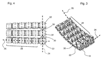
- FIGS. 3 and 4 show a section of the support structure 12.
- a portion of the support chain 24 can be seen, wherein extending away from the support members 22 of the support chain 24 in the illustrated section a rib arm 28.
- the support members 22 of the support chain 24 are connected via connecting elements 30 with each other in a row.
- the connecting elements 30 are designed such that they bend each adjacent Carrying elements 22 of the carrying chain 24 against each other.
- the connecting elements 30 preferably have a force-free neutral position, wherein an opposing force is expended against bending away from this neutral position. It is conceivable that the connecting elements 30 are formed as sprung joints.
- a simple embodiment is, for example, also to connect two adjacent support elements 22 of the support chain 24 with elastically resilient angle (see. FIG. 6 ).
- the respective adjacent support elements 22 are elastically entrained in an active movement of individual support elements 22 of the support chain 24. Thus, a continuous deformation of the support chain 24 can be achieved.
- few actuators can be sufficient for this purpose.
- two actuators 32 are provided, which each have a force acting between the skeleton 14 and the support structure 12 Aktuatorkolben 34.
- Each of the actuator pistons 34 engages an associated pivot point on the support chain 24.
- the articulation point is, for example, on a selected one of the support elements 22.
- FIG. 5 shows a side view of a rib arm 28, which starts from a selected support member 22a of the support chain 24.
- the support elements 22 of the rib arm 28 are pivotally connected to each other via connecting means 30a.
- a bending actuator 36 is provided which has an actuator member extending along the rib chain 26 38 has.
- the actuator member 38 is formed in the example shown by an acting on the support members 22 spindle 38 which extends offset from the articulated connection elements 30a between each two adjacent support members 22 and engages in corresponding engagement portions on the support elements.
- the spindle in this case has a pitch (for example, defined by the pitch of the spindle per revolution), which defines the associated with a spindle rotation bending of the support members against each other.
- FIG. 6 shows a longitudinal section along the support chain 24, in which in the example shown designed as a sprung angle connecting elements 30 between the support members 22 can be seen.
- FIGS. 7 and 8 show in detail representation exemplarily usable gripping devices 18, which can be used in the support members 22 of the support structure 12.
- An operative for exerting a gripping force gripping surface 40 of the individual gripping device 18 is then oriented in the arrangement of the gripping device 18 in the support members 22 so that the gripping surface 40 of the various gripping devices 18 in the total formed gripping surface 20 of the holding device 10 is located.
- the gripping device 18 is designed as a vacuum gripper, wherein the gripping surface 40 has suction openings 42 through which a suction flow can be sucked.
- these have, for example, a connecting piece 44.
- the various connecting pieces 44 can then For example, on the back of the gripping surface 20 of the holding device 10 may be connected to a common vacuum supply system.
- the gripping devices 18 can additionally have individually controllable valves, which are preferably integrated in the gripping devices 18.
- the gripping devices associated supporting elements 22 may include sensors, which are formed, for example, for measuring the between adjacent support elements 22 in the day chain 24 or in a respective rib chain 26.
Landscapes
- Engineering & Computer Science (AREA)
- Mechanical Engineering (AREA)
- Robotics (AREA)
- Manipulator (AREA)
- Clamps And Clips (AREA)
- Chemical & Material Sciences (AREA)
- Composite Materials (AREA)
- Supplying Of Containers To The Packaging Station (AREA)
Priority Applications (3)
| Application Number | Priority Date | Filing Date | Title |
|---|---|---|---|
| EP15168163.2A EP2952302B1 (fr) | 2014-06-05 | 2015-05-19 | Dispositif de retenue ou de préhension |
| US14/727,948 US9555550B2 (en) | 2014-06-05 | 2015-06-02 | Holding device for gripping workpieces with complex shapes or deformable surfaces |
| CN201510303289.9A CN105313039B (zh) | 2014-06-05 | 2015-06-05 | 夹持或固定装置 |
Applications Claiming Priority (2)
| Application Number | Priority Date | Filing Date | Title |
|---|---|---|---|
| DE102014210748 | 2014-06-05 | ||
| EP15168163.2A EP2952302B1 (fr) | 2014-06-05 | 2015-05-19 | Dispositif de retenue ou de préhension |
Publications (3)
| Publication Number | Publication Date |
|---|---|
| EP2952302A2 true EP2952302A2 (fr) | 2015-12-09 |
| EP2952302A3 EP2952302A3 (fr) | 2016-05-18 |
| EP2952302B1 EP2952302B1 (fr) | 2019-03-20 |
Family
ID=55633890
Family Applications (1)
| Application Number | Title | Priority Date | Filing Date |
|---|---|---|---|
| EP15168163.2A Active EP2952302B1 (fr) | 2014-06-05 | 2015-05-19 | Dispositif de retenue ou de préhension |
Country Status (3)
| Country | Link |
|---|---|
| US (1) | US9555550B2 (fr) |
| EP (1) | EP2952302B1 (fr) |
| CN (1) | CN105313039B (fr) |
Cited By (5)
| Publication number | Priority date | Publication date | Assignee | Title |
|---|---|---|---|---|
| CN106826313A (zh) * | 2017-02-07 | 2017-06-13 | 广州纬纶信息科技有限公司 | 一种大板套裁吸盘分区控制方法 |
| WO2018114114A1 (fr) * | 2016-12-23 | 2018-06-28 | Broetje-Automation Gmbh | Effecteur terminal configurable destiné à saisir une pièce plane |
| DE102017223574A1 (de) | 2017-12-21 | 2019-06-27 | Trumpf Werkzeugmaschinen Gmbh + Co. Kg | Verfahren zum Anheben eines plattenförmigen metallischen Werkstücks sowie Be- und/oder Entladevorrichtung |
| CN113401799A (zh) * | 2021-07-21 | 2021-09-17 | 江南造船(集团)有限责任公司 | 一种巨型薄甲板总段的吊装方法 |
| US11267136B2 (en) * | 2015-10-31 | 2022-03-08 | Loop Technology Limited | System for handling flexible materials |
Families Citing this family (11)
| Publication number | Priority date | Publication date | Assignee | Title |
|---|---|---|---|---|
| US9359174B2 (en) * | 2014-02-20 | 2016-06-07 | The Caldwell Group, Inc. | Composite lifting beam |
| EP2952303B1 (fr) | 2014-06-05 | 2017-10-11 | J. Schmalz GmbH | Procédé de manipulation de pièces souples du type matelas |
| JP6367158B2 (ja) * | 2015-07-13 | 2018-08-01 | 三菱重工業株式会社 | 吸着装置、把持装置および搬送方法 |
| CN205554727U (zh) * | 2016-04-14 | 2016-09-07 | 日东电工株式会社 | 吸附部件、液晶单元吸附移动装置、及光学膜贴合生产线 |
| JP6201082B1 (ja) * | 2016-04-14 | 2017-09-20 | 日東電工株式会社 | 吸着部材、液晶セル吸着移動装置、および光学フィルム貼合せライン |
| CN109313867A (zh) * | 2016-05-31 | 2019-02-05 | 堺显示器制品株式会社 | 基板保持装置 |
| WO2018172022A1 (fr) * | 2017-03-22 | 2018-09-27 | Saint-Gobain Glass France | Dispositif et procédé destinés à recevoir, à déformer et à déposer une plaque de verre mince |
| CN106926264B (zh) * | 2017-04-13 | 2023-08-29 | 浙江工业大学 | 一种增加柔性胶粘附力的抓取装置 |
| JP6878117B2 (ja) * | 2017-04-25 | 2021-05-26 | 川崎重工業株式会社 | シート搬送装置及びシート搬送方法 |
| US10195747B1 (en) * | 2017-08-03 | 2019-02-05 | General Electric Company | Multi-faced apparatus and system for automated handling of components |
| IT202000015316A1 (it) * | 2020-06-25 | 2021-12-25 | Euromatic Srl | Testa di robot per il prelievo di contenitori in vetro |
Citations (1)
| Publication number | Priority date | Publication date | Assignee | Title |
|---|---|---|---|---|
| DE102013201765A1 (de) | 2013-02-04 | 2014-08-07 | J. Schmalz Gmbh | Spannvorrichtung |
Family Cites Families (17)
| Publication number | Priority date | Publication date | Assignee | Title |
|---|---|---|---|---|
| US3720433A (en) * | 1970-09-29 | 1973-03-13 | Us Navy | Manipulator apparatus for gripping submerged objects |
| CH520016A (de) * | 1971-03-18 | 1972-03-15 | Tourpac Ag | Vorrichtung zur Herstellung von gefüllten evakuierten Packungen und Verfahren zum Betrieb der Vorrichtung |
| US3837782A (en) * | 1971-12-15 | 1974-09-24 | Filper Corp | Apparatus for forming containers |
| JPS538418B2 (fr) * | 1973-11-16 | 1978-03-28 | ||
| DE3939349A1 (de) * | 1989-11-29 | 1991-06-06 | Krupp Gmbh | Einrichtung zur handhabung insbesondere von gegenstaenden aus nachgiebigen werkstoffen |
| IT1255607B (it) * | 1992-09-21 | 1995-11-09 | Dispositivo per il bloccaggio ed il mantenimento in posizione di lastre di vetro sagomabili durante la loro lavorazione. | |
| DE19817426B4 (de) * | 1998-04-18 | 2004-06-09 | J. Schmalz Gmbh | Greifersystem, insbesondere Vakuumgreifersystem |
| JP4761341B2 (ja) * | 2002-11-21 | 2011-08-31 | 株式会社ブリヂストン | 吸着搬送装置 |
| DE102004031863B3 (de) * | 2004-07-01 | 2006-03-09 | Airbus Deutschland Gmbh | Vorrichtung zur Fixierung von insbesondere flächenhaften Werkstücken mit einer Anlagefläche |
| DE202007013673U1 (de) * | 2007-09-28 | 2009-02-19 | Kuka Systems Gmbh | Flexible Greifeinrichtung |
| DE102009043043B4 (de) * | 2009-09-28 | 2013-05-29 | Deutsche Post Ag | Sauggreifer zum Aufnehmen und Absetzen von Stückgut |
| DE102011106214A1 (de) * | 2011-06-07 | 2012-12-13 | Brötje-Automation GmbH | Endeffektor |
| DE102011056029A1 (de) * | 2011-12-05 | 2013-06-06 | Rehau Ag + Co | Transportverfahren zur Ablage von Fasermatten, Transportvorrichtung sowie eine Vorrichtung zum Greifen eines flächigen Halbzeugs |
| DE102012003094B4 (de) | 2012-02-09 | 2019-01-31 | Technische Universität Braunschweig Carolo-Wilhelmina | Vorrichtung zum Halten und/oder Verformen eines Objektes sowie Verfahren zum Verformen eines Objektes |
| DE102012215513A1 (de) * | 2012-08-31 | 2014-03-06 | J. Schmalz Gmbh | Greifvorrichtung |
| DE102012019958A1 (de) | 2012-10-09 | 2013-04-11 | Daimler Ag | Verfahren zur Herstellung eines Bauteils aus faserverstärktem Kunststoff und Vorrichtung zur Durchführung des Verfahrens |
| EP2952303B1 (fr) * | 2014-06-05 | 2017-10-11 | J. Schmalz GmbH | Procédé de manipulation de pièces souples du type matelas |
-
2015
- 2015-05-19 EP EP15168163.2A patent/EP2952302B1/fr active Active
- 2015-06-02 US US14/727,948 patent/US9555550B2/en active Active
- 2015-06-05 CN CN201510303289.9A patent/CN105313039B/zh active Active
Patent Citations (1)
| Publication number | Priority date | Publication date | Assignee | Title |
|---|---|---|---|---|
| DE102013201765A1 (de) | 2013-02-04 | 2014-08-07 | J. Schmalz Gmbh | Spannvorrichtung |
Cited By (7)
| Publication number | Priority date | Publication date | Assignee | Title |
|---|---|---|---|---|
| US11267136B2 (en) * | 2015-10-31 | 2022-03-08 | Loop Technology Limited | System for handling flexible materials |
| WO2018114114A1 (fr) * | 2016-12-23 | 2018-06-28 | Broetje-Automation Gmbh | Effecteur terminal configurable destiné à saisir une pièce plane |
| CN106826313A (zh) * | 2017-02-07 | 2017-06-13 | 广州纬纶信息科技有限公司 | 一种大板套裁吸盘分区控制方法 |
| DE102017223574A1 (de) | 2017-12-21 | 2019-06-27 | Trumpf Werkzeugmaschinen Gmbh + Co. Kg | Verfahren zum Anheben eines plattenförmigen metallischen Werkstücks sowie Be- und/oder Entladevorrichtung |
| WO2019121110A1 (fr) | 2017-12-21 | 2019-06-27 | Trumpf Werkzeugmaschinen Gmbh + Co. Kg | Procédé permettant de soulever une pièce métallique en forme de plaque ainsi que dispositif de chargement et/ou de déchargement |
| CN113401799A (zh) * | 2021-07-21 | 2021-09-17 | 江南造船(集团)有限责任公司 | 一种巨型薄甲板总段的吊装方法 |
| CN113401799B (zh) * | 2021-07-21 | 2022-12-20 | 江南造船(集团)有限责任公司 | 一种巨型薄甲板总段的吊装方法 |
Also Published As
| Publication number | Publication date |
|---|---|
| CN105313039B (zh) | 2018-02-13 |
| CN105313039A (zh) | 2016-02-10 |
| EP2952302A3 (fr) | 2016-05-18 |
| EP2952302B1 (fr) | 2019-03-20 |
| US9555550B2 (en) | 2017-01-31 |
| US20150367517A1 (en) | 2015-12-24 |
Similar Documents
| Publication | Publication Date | Title |
|---|---|---|
| EP2952302B1 (fr) | Dispositif de retenue ou de préhension | |
| DE102017107244B4 (de) | Haltevorrichtung für einen Roboter | |
| EP2101963B1 (fr) | Mécanisme vermiculaire | |
| EP0499943B1 (fr) | Dispositif pour la mise en oeuvre d'éssais par contraintes en flexion alternées à 4 points d'appui | |
| EP1481169B1 (fr) | Actionneur pneumatique | |
| DE102009057585B4 (de) | Verfahren zum Kalibrieren eines Roboters | |
| EP2734462B1 (fr) | Dispositif et procédé permettant d'arrêter et/ou d'orienter des produits transportés sur un convoyeur, et convoyeur | |
| DE102005010380B4 (de) | Greifwerkzeug mit selbstadaptiver Kinematik | |
| EP0168764A2 (fr) | Jeu de pièces pour la production d'un gabarit de montage pour des tuyauteries, en particulier des tuyauteries pour des circuits hydrauliques ou pneumatiques de communication ou de travail | |
| DE102014223118A1 (de) | Greifvorrichtung | |
| EP2952303B1 (fr) | Procédé de manipulation de pièces souples du type matelas | |
| DE202012100849U1 (de) | Nadelgreifer für Textil- und Schaumstoffplatten | |
| DE10032754C1 (de) | Greifvorrichtung für dünne, plattenförmige Teile | |
| DE102009024308A1 (de) | Antriebsanordnung für einen länglichen Schwingkörper | |
| DE102010019704B4 (de) | Schiffchen-Stickmaschine mit Antrieb des Treiberbalkens | |
| DE102013013555B4 (de) | Haltevorrichtung zum Festhalten von Gegenständen | |
| DE102008010269A1 (de) | Positioniervorrichtung zum Bewegen und Ausrichten eines Objektes im Raum | |
| EP2735408B1 (fr) | Dispositif de saisie destiné à saisir des objets | |
| DE102020215228B3 (de) | Greifvorrichtung zum Greifen von Objekten und Verfahren zum Betreiben einer solchen Greifvorrichtung | |
| EP2735409B1 (fr) | Dispositif de saisie destiné à saisir des objets | |
| DE102008050519A1 (de) | Schwenkbarer Flansch | |
| DE102010025392A1 (de) | Handhabungssystem zur Aufnahme von wenigstens zwei räumlich geordneten Werkstücken und Abgeben der Werkstücke mit einer geordnet veränderten Relativlage der Werkstücke | |
| DE102013222108B3 (de) | Tragerahmen für eine Handhabungsvorrichtung, sowieHandhabungsvorrichtung | |
| DE102008056662B4 (de) | Segmentkörper und Abstreifer für einen Fördergurtabstreifer | |
| DE202010015845U1 (de) | Vorrichtung für die Montage von Karosserieteilen an Fahrzeugkarosserien |
Legal Events
| Date | Code | Title | Description |
|---|---|---|---|
| PUAI | Public reference made under article 153(3) epc to a published international application that has entered the european phase |
Free format text: ORIGINAL CODE: 0009012 |
|
| AK | Designated contracting states |
Kind code of ref document: A2 Designated state(s): AL AT BE BG CH CY CZ DE DK EE ES FI FR GB GR HR HU IE IS IT LI LT LU LV MC MK MT NL NO PL PT RO RS SE SI SK SM TR |
|
| AX | Request for extension of the european patent |
Extension state: BA ME |
|
| PUAL | Search report despatched |
Free format text: ORIGINAL CODE: 0009013 |
|
| AK | Designated contracting states |
Kind code of ref document: A3 Designated state(s): AL AT BE BG CH CY CZ DE DK EE ES FI FR GB GR HR HU IE IS IT LI LT LU LV MC MK MT NL NO PL PT RO RS SE SI SK SM TR |
|
| AX | Request for extension of the european patent |
Extension state: BA ME |
|
| RIC1 | Information provided on ipc code assigned before grant |
Ipc: B25J 15/00 20060101AFI20160411BHEP Ipc: B25J 15/06 20060101ALI20160411BHEP |
|
| RIN1 | Information on inventor provided before grant (corrected) |
Inventor name: EISELE, THOMAS Inventor name: DUNKMANN, WALTER Inventor name: DEFRANCESKI, ALINE Inventor name: FRITZ, FLORIAN Inventor name: REINISCH, HERMANN Inventor name: KUOLT, HARALD DR. Inventor name: EBERLE, MARCUS |
|
| 17P | Request for examination filed |
Effective date: 20161012 |
|
| RBV | Designated contracting states (corrected) |
Designated state(s): AL AT BE BG CH CY CZ DE DK EE ES FI FR GB GR HR HU IE IS IT LI LT LU LV MC MK MT NL NO PL PT RO RS SE SI SK SM TR |
|
| STAA | Information on the status of an ep patent application or granted ep patent |
Free format text: STATUS: REQUEST FOR EXAMINATION WAS MADE |
|
| R17P | Request for examination filed (corrected) |
Effective date: 20161012 |
|
| RIN1 | Information on inventor provided before grant (corrected) |
Inventor name: FRITZ, FLORIAN Inventor name: DUNKMANN, WALTER Inventor name: EISELE, THOMAS Inventor name: REINISCH, HERMANN Inventor name: DEFRANCESKI, ALINE Inventor name: KUOLT, HARALD DR. Inventor name: EBERLE, MARCUS |
|
| STAA | Information on the status of an ep patent application or granted ep patent |
Free format text: STATUS: EXAMINATION IS IN PROGRESS |
|
| 17Q | First examination report despatched |
Effective date: 20170526 |
|
| RAP1 | Party data changed (applicant data changed or rights of an application transferred) |
Owner name: J. SCHMALZ GMBH |
|
| RIC1 | Information provided on ipc code assigned before grant |
Ipc: B25J 15/06 20060101ALI20180824BHEP Ipc: B25J 15/00 20060101AFI20180824BHEP Ipc: B29C 70/54 20060101ALI20180824BHEP |
|
| GRAP | Despatch of communication of intention to grant a patent |
Free format text: ORIGINAL CODE: EPIDOSNIGR1 |
|
| STAA | Information on the status of an ep patent application or granted ep patent |
Free format text: STATUS: GRANT OF PATENT IS INTENDED |
|
| INTG | Intention to grant announced |
Effective date: 20181012 |
|
| RIN1 | Information on inventor provided before grant (corrected) |
Inventor name: DEFRANCESKI, ALINE Inventor name: FRITZ, FLORIAN Inventor name: KUOLT, HARALD DR. Inventor name: REINISCH, HERMANN Inventor name: EISELE, THOMAS Inventor name: EBERLE, MARCUS Inventor name: DUNKMANN, WALTER |
|
| GRAS | Grant fee paid |
Free format text: ORIGINAL CODE: EPIDOSNIGR3 |
|
| GRAA | (expected) grant |
Free format text: ORIGINAL CODE: 0009210 |
|
| STAA | Information on the status of an ep patent application or granted ep patent |
Free format text: STATUS: THE PATENT HAS BEEN GRANTED |
|
| AK | Designated contracting states |
Kind code of ref document: B1 Designated state(s): AL AT BE BG CH CY CZ DE DK EE ES FI FR GB GR HR HU IE IS IT LI LT LU LV MC MK MT NL NO PL PT RO RS SE SI SK SM TR |
|
| REG | Reference to a national code |
Ref country code: GB Ref legal event code: FG4D Free format text: NOT ENGLISH |
|
| REG | Reference to a national code |
Ref country code: CH Ref legal event code: EP |
|
| REG | Reference to a national code |
Ref country code: DE Ref legal event code: R096 Ref document number: 502015008385 Country of ref document: DE |
|
| REG | Reference to a national code |
Ref country code: AT Ref legal event code: REF Ref document number: 1110067 Country of ref document: AT Kind code of ref document: T Effective date: 20190415 |
|
| REG | Reference to a national code |
Ref country code: IE Ref legal event code: FG4D Free format text: LANGUAGE OF EP DOCUMENT: GERMAN |
|
| REG | Reference to a national code |
Ref country code: NL Ref legal event code: MP Effective date: 20190320 |
|
| PG25 | Lapsed in a contracting state [announced via postgrant information from national office to epo] |
Ref country code: SE Free format text: LAPSE BECAUSE OF FAILURE TO SUBMIT A TRANSLATION OF THE DESCRIPTION OR TO PAY THE FEE WITHIN THE PRESCRIBED TIME-LIMIT Effective date: 20190320 Ref country code: FI Free format text: LAPSE BECAUSE OF FAILURE TO SUBMIT A TRANSLATION OF THE DESCRIPTION OR TO PAY THE FEE WITHIN THE PRESCRIBED TIME-LIMIT Effective date: 20190320 Ref country code: NO Free format text: LAPSE BECAUSE OF FAILURE TO SUBMIT A TRANSLATION OF THE DESCRIPTION OR TO PAY THE FEE WITHIN THE PRESCRIBED TIME-LIMIT Effective date: 20190620 Ref country code: LT Free format text: LAPSE BECAUSE OF FAILURE TO SUBMIT A TRANSLATION OF THE DESCRIPTION OR TO PAY THE FEE WITHIN THE PRESCRIBED TIME-LIMIT Effective date: 20190320 |
|
| REG | Reference to a national code |
Ref country code: LT Ref legal event code: MG4D |
|
| PG25 | Lapsed in a contracting state [announced via postgrant information from national office to epo] |
Ref country code: GR Free format text: LAPSE BECAUSE OF FAILURE TO SUBMIT A TRANSLATION OF THE DESCRIPTION OR TO PAY THE FEE WITHIN THE PRESCRIBED TIME-LIMIT Effective date: 20190621 Ref country code: RS Free format text: LAPSE BECAUSE OF FAILURE TO SUBMIT A TRANSLATION OF THE DESCRIPTION OR TO PAY THE FEE WITHIN THE PRESCRIBED TIME-LIMIT Effective date: 20190320 Ref country code: NL Free format text: LAPSE BECAUSE OF FAILURE TO SUBMIT A TRANSLATION OF THE DESCRIPTION OR TO PAY THE FEE WITHIN THE PRESCRIBED TIME-LIMIT Effective date: 20190320 Ref country code: HR Free format text: LAPSE BECAUSE OF FAILURE TO SUBMIT A TRANSLATION OF THE DESCRIPTION OR TO PAY THE FEE WITHIN THE PRESCRIBED TIME-LIMIT Effective date: 20190320 Ref country code: LV Free format text: LAPSE BECAUSE OF FAILURE TO SUBMIT A TRANSLATION OF THE DESCRIPTION OR TO PAY THE FEE WITHIN THE PRESCRIBED TIME-LIMIT Effective date: 20190320 Ref country code: BG Free format text: LAPSE BECAUSE OF FAILURE TO SUBMIT A TRANSLATION OF THE DESCRIPTION OR TO PAY THE FEE WITHIN THE PRESCRIBED TIME-LIMIT Effective date: 20190620 |
|
| PG25 | Lapsed in a contracting state [announced via postgrant information from national office to epo] |
Ref country code: AL Free format text: LAPSE BECAUSE OF FAILURE TO SUBMIT A TRANSLATION OF THE DESCRIPTION OR TO PAY THE FEE WITHIN THE PRESCRIBED TIME-LIMIT Effective date: 20190320 Ref country code: ES Free format text: LAPSE BECAUSE OF FAILURE TO SUBMIT A TRANSLATION OF THE DESCRIPTION OR TO PAY THE FEE WITHIN THE PRESCRIBED TIME-LIMIT Effective date: 20190320 Ref country code: RO Free format text: LAPSE BECAUSE OF FAILURE TO SUBMIT A TRANSLATION OF THE DESCRIPTION OR TO PAY THE FEE WITHIN THE PRESCRIBED TIME-LIMIT Effective date: 20190320 Ref country code: IT Free format text: LAPSE BECAUSE OF FAILURE TO SUBMIT A TRANSLATION OF THE DESCRIPTION OR TO PAY THE FEE WITHIN THE PRESCRIBED TIME-LIMIT Effective date: 20190320 Ref country code: CZ Free format text: LAPSE BECAUSE OF FAILURE TO SUBMIT A TRANSLATION OF THE DESCRIPTION OR TO PAY THE FEE WITHIN THE PRESCRIBED TIME-LIMIT Effective date: 20190320 Ref country code: EE Free format text: LAPSE BECAUSE OF FAILURE TO SUBMIT A TRANSLATION OF THE DESCRIPTION OR TO PAY THE FEE WITHIN THE PRESCRIBED TIME-LIMIT Effective date: 20190320 Ref country code: SK Free format text: LAPSE BECAUSE OF FAILURE TO SUBMIT A TRANSLATION OF THE DESCRIPTION OR TO PAY THE FEE WITHIN THE PRESCRIBED TIME-LIMIT Effective date: 20190320 Ref country code: PT Free format text: LAPSE BECAUSE OF FAILURE TO SUBMIT A TRANSLATION OF THE DESCRIPTION OR TO PAY THE FEE WITHIN THE PRESCRIBED TIME-LIMIT Effective date: 20190720 |
|
| PG25 | Lapsed in a contracting state [announced via postgrant information from national office to epo] |
Ref country code: PL Free format text: LAPSE BECAUSE OF FAILURE TO SUBMIT A TRANSLATION OF THE DESCRIPTION OR TO PAY THE FEE WITHIN THE PRESCRIBED TIME-LIMIT Effective date: 20190320 Ref country code: SM Free format text: LAPSE BECAUSE OF FAILURE TO SUBMIT A TRANSLATION OF THE DESCRIPTION OR TO PAY THE FEE WITHIN THE PRESCRIBED TIME-LIMIT Effective date: 20190320 |
|
| REG | Reference to a national code |
Ref country code: CH Ref legal event code: PL |
|
| PG25 | Lapsed in a contracting state [announced via postgrant information from national office to epo] |
Ref country code: IS Free format text: LAPSE BECAUSE OF FAILURE TO SUBMIT A TRANSLATION OF THE DESCRIPTION OR TO PAY THE FEE WITHIN THE PRESCRIBED TIME-LIMIT Effective date: 20190720 |
|
| REG | Reference to a national code |
Ref country code: DE Ref legal event code: R097 Ref document number: 502015008385 Country of ref document: DE |
|
| PLBE | No opposition filed within time limit |
Free format text: ORIGINAL CODE: 0009261 |
|
| STAA | Information on the status of an ep patent application or granted ep patent |
Free format text: STATUS: NO OPPOSITION FILED WITHIN TIME LIMIT |
|
| PG25 | Lapsed in a contracting state [announced via postgrant information from national office to epo] |
Ref country code: MC Free format text: LAPSE BECAUSE OF FAILURE TO SUBMIT A TRANSLATION OF THE DESCRIPTION OR TO PAY THE FEE WITHIN THE PRESCRIBED TIME-LIMIT Effective date: 20190320 Ref country code: LI Free format text: LAPSE BECAUSE OF NON-PAYMENT OF DUE FEES Effective date: 20190531 Ref country code: DK Free format text: LAPSE BECAUSE OF FAILURE TO SUBMIT A TRANSLATION OF THE DESCRIPTION OR TO PAY THE FEE WITHIN THE PRESCRIBED TIME-LIMIT Effective date: 20190320 Ref country code: CH Free format text: LAPSE BECAUSE OF NON-PAYMENT OF DUE FEES Effective date: 20190531 |
|
| REG | Reference to a national code |
Ref country code: BE Ref legal event code: MM Effective date: 20190531 |
|
| 26N | No opposition filed |
Effective date: 20200102 |
|
| PG25 | Lapsed in a contracting state [announced via postgrant information from national office to epo] |
Ref country code: LU Free format text: LAPSE BECAUSE OF NON-PAYMENT OF DUE FEES Effective date: 20190519 Ref country code: SI Free format text: LAPSE BECAUSE OF FAILURE TO SUBMIT A TRANSLATION OF THE DESCRIPTION OR TO PAY THE FEE WITHIN THE PRESCRIBED TIME-LIMIT Effective date: 20190320 |
|
| PG25 | Lapsed in a contracting state [announced via postgrant information from national office to epo] |
Ref country code: TR Free format text: LAPSE BECAUSE OF FAILURE TO SUBMIT A TRANSLATION OF THE DESCRIPTION OR TO PAY THE FEE WITHIN THE PRESCRIBED TIME-LIMIT Effective date: 20190320 |
|
| PG25 | Lapsed in a contracting state [announced via postgrant information from national office to epo] |
Ref country code: IE Free format text: LAPSE BECAUSE OF NON-PAYMENT OF DUE FEES Effective date: 20190519 |
|
| PG25 | Lapsed in a contracting state [announced via postgrant information from national office to epo] |
Ref country code: BE Free format text: LAPSE BECAUSE OF NON-PAYMENT OF DUE FEES Effective date: 20190531 |
|
| PG25 | Lapsed in a contracting state [announced via postgrant information from national office to epo] |
Ref country code: CY Free format text: LAPSE BECAUSE OF FAILURE TO SUBMIT A TRANSLATION OF THE DESCRIPTION OR TO PAY THE FEE WITHIN THE PRESCRIBED TIME-LIMIT Effective date: 20190320 |
|
| PG25 | Lapsed in a contracting state [announced via postgrant information from national office to epo] |
Ref country code: HU Free format text: LAPSE BECAUSE OF FAILURE TO SUBMIT A TRANSLATION OF THE DESCRIPTION OR TO PAY THE FEE WITHIN THE PRESCRIBED TIME-LIMIT; INVALID AB INITIO Effective date: 20150519 Ref country code: MT Free format text: LAPSE BECAUSE OF FAILURE TO SUBMIT A TRANSLATION OF THE DESCRIPTION OR TO PAY THE FEE WITHIN THE PRESCRIBED TIME-LIMIT Effective date: 20190320 |
|
| PG25 | Lapsed in a contracting state [announced via postgrant information from national office to epo] |
Ref country code: MK Free format text: LAPSE BECAUSE OF FAILURE TO SUBMIT A TRANSLATION OF THE DESCRIPTION OR TO PAY THE FEE WITHIN THE PRESCRIBED TIME-LIMIT Effective date: 20190320 |
|
| P01 | Opt-out of the competence of the unified patent court (upc) registered |
Effective date: 20230601 |
|
| PGFP | Annual fee paid to national office [announced via postgrant information from national office to epo] |
Ref country code: DE Payment date: 20230724 Year of fee payment: 9 |
|
| PGFP | Annual fee paid to national office [announced via postgrant information from national office to epo] |
Ref country code: GB Payment date: 20240513 Year of fee payment: 10 |
|
| PGFP | Annual fee paid to national office [announced via postgrant information from national office to epo] |
Ref country code: AT Payment date: 20240517 Year of fee payment: 10 |
|
| PGFP | Annual fee paid to national office [announced via postgrant information from national office to epo] |
Ref country code: FR Payment date: 20240516 Year of fee payment: 10 |