EP2952139B1 - Exposure apparatus for spinal posterior minimally invasive screw fixation surgery - Google Patents
Exposure apparatus for spinal posterior minimally invasive screw fixation surgery Download PDFInfo
- Publication number
- EP2952139B1 EP2952139B1 EP13873354.8A EP13873354A EP2952139B1 EP 2952139 B1 EP2952139 B1 EP 2952139B1 EP 13873354 A EP13873354 A EP 13873354A EP 2952139 B1 EP2952139 B1 EP 2952139B1
- Authority
- EP
- European Patent Office
- Prior art keywords
- retractor
- handle
- retractor body
- transverse process
- minimally invasive
- Prior art date
- Legal status (The legal status is an assumption and is not a legal conclusion. Google has not performed a legal analysis and makes no representation as to the accuracy of the status listed.)
- Not-in-force
Links
Images

Classifications
-
- A—HUMAN NECESSITIES
- A61—MEDICAL OR VETERINARY SCIENCE; HYGIENE
- A61B—DIAGNOSIS; SURGERY; IDENTIFICATION
- A61B17/00—Surgical instruments, devices or methods
- A61B17/02—Surgical instruments, devices or methods for holding wounds open, e.g. retractors; Tractors
- A61B17/0218—Surgical instruments, devices or methods for holding wounds open, e.g. retractors; Tractors for minimally invasive surgery
-
- A—HUMAN NECESSITIES
- A61—MEDICAL OR VETERINARY SCIENCE; HYGIENE
- A61B—DIAGNOSIS; SURGERY; IDENTIFICATION
- A61B17/00—Surgical instruments, devices or methods
- A61B17/02—Surgical instruments, devices or methods for holding wounds open, e.g. retractors; Tractors
-
- A—HUMAN NECESSITIES
- A61—MEDICAL OR VETERINARY SCIENCE; HYGIENE
- A61B—DIAGNOSIS; SURGERY; IDENTIFICATION
- A61B17/00—Surgical instruments, devices or methods
- A61B17/02—Surgical instruments, devices or methods for holding wounds open, e.g. retractors; Tractors
- A61B17/025—Joint distractors
-
- A—HUMAN NECESSITIES
- A61—MEDICAL OR VETERINARY SCIENCE; HYGIENE
- A61B—DIAGNOSIS; SURGERY; IDENTIFICATION
- A61B17/00—Surgical instruments, devices or methods
- A61B17/02—Surgical instruments, devices or methods for holding wounds open, e.g. retractors; Tractors
- A61B17/025—Joint distractors
- A61B2017/0256—Joint distractors for the spine
-
- A—HUMAN NECESSITIES
- A61—MEDICAL OR VETERINARY SCIENCE; HYGIENE
- A61B—DIAGNOSIS; SURGERY; IDENTIFICATION
- A61B90/00—Instruments, implements or accessories specially adapted for surgery or diagnosis and not covered by any of the groups A61B1/00 - A61B50/00, e.g. for luxation treatment or for protecting wound edges
- A61B90/08—Accessories or related features not otherwise provided for
- A61B2090/0807—Indication means
Definitions
- the present invention relates to an exposure apparatus for posterior spinal minimally invasive screw placement surgery, which belongs to the field of medical appliances.
- pedicle screw technology has been developed quickly since its introduction in 1980s and has been widely used in surgical treatment on affections such as spinal degeneration, spondylolisthesis, spinal stenosis, vertebral fracture, malformation, metastatic tumor of bone, spinal instability and the like.
- the pedicle screw is one of the internal fixation instruments most widely used in a spine surgery, and methods for embedding the pedicle screw mainly include: 1.
- a posterior medisection screw placement surgery which is a conventional surgery manner, is extensive in clinical application presently, and widely accepted by most of the clinicists, but it has some major defects of larger surgery wound, difficult exposure of a needle inlet point at the pedicle, more bleeding, longer postoperative recovery time for the patients, multiple combination of atrophy of longissimus muscle and multifidus muscle, instability due to ligament damage, and long-dated lumbago left on partial sufferers; 2.
- minimally invasive spine technology i.e., posterior channel aided minimally invasive screw placement technology, which conducts the operation of placing a spinal pedicle screw with the help of such special surgery appliances and instruments like medical images, aided channel expansion and microscopic endoscope or the like, achieves the optimal therapeutic effect with minimal injury, and has the advatanges of short surgical incision, small wound, less bleeding, rapid postoperative function recovery, and reduction of incidence of postoperative pains on the waist and back as compared with the conventional method.
- a new minimally invasive technology which has the advantages of short surgical incision, small wound, less bleeding, rapid postoperative function recovery that are similar to a minimally invasive surgery, is simple and effective, and is easy to grasp, is needed in clinic presently.
- the inventor redesigns a set of surgical manner and surgical instrument, and improves the posterior spinal minimally invasive technology, which is simple and convenient, easier to grasp, has smaller wound than that of the conventional minimally invasive surgery, while the exposure apparatus for posterior spinal small incision pedicle screw placement is just a part thereof.
- the conventional posterior spinal minimally invasive screw placement technology generally employs a kirschner wire to puncture and position the pedicle and then incise the skin, use an expander to expand from small to big in sequence till obtaining a satisfactory size, wherein the puncture approach may deviate a gap between the multifidus muscle and the longissimus muscle and enter the multifidus muscle or the longissimus muscle to cause injury of the multifidus muscle and the longissimus muscle, and meanwhile, the expansion process thereof is to tear and draw local muscles actually, which further aggravates the muscular injury.
- Document WO 2012/159088 A1 describes an adjustable system for supporting surgical tools.
- This document shows a retractor, suitable as a facet joint retractor, the retractor having a handle and a retractor body, the retractor body having a horizontal segment, the handle extending upwardly from a first end of the horizontal segment at an angle of 165+/- 15 degrees, the retractor body having a vertical segment having a first end and a second end, extending downwardly from the second end of the horizontal segment at an angle of 80+/-10 degrees, the retractor body having a further bent segment, extending from the second end of the vertical segment, which is not connected to the horizontal, towards the direction of the handle.
- Document WO 2011/126803 A2 relates to a surgical implement with suction and irrigation passages.
- the object of the present invention is to provide an exposure apparatus which can assist to accurately, quickly and conveniently conduct pedicle screw placement during a posterior minimally invasive screw placement surgery, wherein the apparatus can be used to separate a gap between a multifidus muscle and a longissimus muscle under direct vision, and can easily and non-invasively reach a screw placement position on a pedicle. Meanwhile, during a screw placement operation, the distal end of the transverse process retractor can straddle above the transverse process and is antagonistically tractive with the facet joint retractor so as to leave a sufficient space for the screw placement operation and to prompt a needle inlet point and direction for placing the pedicle screw.
- an exposure apparatus for posterior spinal minimally invasive screw placement surgery includes a transverse process retractor and a facet joint retractor used cooperatively with the transverse process retractor, the transverse process retractor consists of a first handle and a first retractor body, wherein the first retractor body is an L-shaped metal bar having an angle of 100 ⁇ 10 degrees, which satisfies the demand of externally extending 10 to 15 degrees during screw placement, and facilitates the placment of the pedicle screw; one end of the first retractor is fixedly connected to the first handle, the other end of the first retractor bends towards the direction of the first handle, and the end is provided with a crescent type recess, so that the transverse process retractor can easily straddle above the transverse process during the surgery and is located in the center of the transverse process; the facet joint retractor consists of a second handle and a second retractor body, wherein the second retractor body is an L-shaped metal bar having an angle of 80 ⁇ 10 degrees,
- both the first retractor body and the second retractor body include a horizontal segment and a vertical segment, wherein a angle of 165 ⁇ 15 degrees is formed between the first handle and the second handle and their horizontal segment thereof, both the first handle and the second handle are located at one side of the horizontal segment opposite to the vertical segment so as to be convenient for holding during traction in the surgery, and reduce the influences of tissues surrounding an iincision placing the retractor; the other ends of the first retractor body and the second retractor body respectively bend by 10 ⁇ 10 degrees towards the directions of the first handle and the second handle respectively, and the bending lengths of the first retractor body and the second retractor body are 5 ⁇ 3mm.
- both the connected ends of the first handle and the second handle are fishmouth shaped flat structures, which avoid the oppression of the retractor on the tissues during the surgery, and are beneficial for operating the surgery; both the thicknesses of the first retractor body and the second retractor body are 2 ⁇ 1mm, and both the widths thereof are 12 ⁇ 5mm; and both the lengths of the horizontal segment of the first retractor body and the second retractor body are 100 ⁇ 50mm.
- the length of the vertical segment of the first retractor body is 60 ⁇ 10 or 75 ⁇ 5mm; and the length of the vertical segment of the second retractor body is 50 ⁇ 10 or 65 ⁇ 5mm.
- the outer surfaces of the holding portions of the first handle and the second handle are subject to roughened treatment, which are convenient for holding during the surgery.
- the outside of the vertical segment of the transverse process retractor is provided with a prompt line for prompting a needle inlet point and direction for placing a pedicle screw. After the transverse process retractor is accurately placed during the surgery, the pedicle screw can be placed according to the prompt direction on the retractor.
- the present invention has the advantageous effects that.
- an exposure apparatus for posterior spinal minimally invasive screw placement surgery includes a transverse process retractor and a facet joint retractor used cooperatively with the transverse process retractor.
- the transverse process retractor consists of a first handle 1 and a first retractor body 2, wherein the first retractor body 2 is an L-shaped metal bar having an included angle of 100 degrees, one end of the first retractor body 2 is fixedly connected to the first handle 1, the other end of the first retractor bends towards the direction of the first handle 1, and the end is provided with a crescent type recess.
- the facet joint retractor consists of a second handle 3 and a second retractor body 4, wherein the second retractor body 4 is an L-shaped metal bar having an included angle of 80 degrees, one end of the second retractor body 4 is fixedly connected to the second handle 3, the other end of the second retractor body bends towards the direction of the second handle 3, and the end is provided with a crescent type recess.
- Both the first retractor body 2 and the second retractor body 4 include a horizontal segment and a vertical segment, wherein a angle of 165 degrees is formed between the horizontal segment of the first handle 1 and the second handle 3, both the first handle 1 and the second handle 3 are located at one side of the horizontal segment opposite to the vertical segment, the other ends of the first retractor body 2 and the second retractor body 4 respectively bend by 10 ⁇ 10 degrees towards the directions of the first handle 1 and the second handle 3 respectively, and both the bending lengths of the first retractor body and the second retractor body are 5 ⁇ 3mm.
- Both the connected ends of the first handle 1 and the second handle 3 are fishmouth shaped flat structures, both the lengths of the first handle 1 and the second handle 3 are 120mm, wherein the length of the holding portion is 100mm, both the firs handle and the second handle are circular columns having a diameter of 20mm, and the outer surfaces of the holding portions of the first handle 1 and the second handle 3 are subject to roughened treatment.
- Both the thicknesses of the first retractor body 2 and the second retractor body 4 are 2mm, and the widths thereof are both 12mm; and both the lengths of the horizontal segments of the first retractor body 2 and the second retractor body 4 are 1 00mm.
- the length of the vertical segment of the first retractor body 2 is 60 or 75mm; and the length of the vertical segment of the second retractor body 4 is 50 or 65mm.
- the outside of the vertical segment of the transverse process retractor is provided with a prompt line 5 for prompting a needle inlet point and direction for placing a pedicle screw.
Landscapes
- Health & Medical Sciences (AREA)
- Life Sciences & Earth Sciences (AREA)
- Surgery (AREA)
- Heart & Thoracic Surgery (AREA)
- Engineering & Computer Science (AREA)
- Biomedical Technology (AREA)
- Nuclear Medicine, Radiotherapy & Molecular Imaging (AREA)
- Medical Informatics (AREA)
- Molecular Biology (AREA)
- Animal Behavior & Ethology (AREA)
- General Health & Medical Sciences (AREA)
- Public Health (AREA)
- Veterinary Medicine (AREA)
- Surgical Instruments (AREA)
- Prostheses (AREA)
Description
- The present invention relates to an exposure apparatus for posterior spinal minimally invasive screw placement surgery, which belongs to the field of medical appliances.
- Pedicle screw technology has been developed quickly since its introduction in 1980s and has been widely used in surgical treatment on affections such as spinal degeneration, spondylolisthesis, spinal stenosis, vertebral fracture, malformation, metastatic tumor of bone, spinal instability and the like. At present, the pedicle screw is one of the internal fixation instruments most widely used in a spine surgery, and methods for embedding the pedicle screw mainly include: 1. a posterior medisection screw placement surgery, which is a conventional surgery manner, is extensive in clinical application presently, and widely accepted by most of the clinicists, but it has some major defects of larger surgery wound, difficult exposure of a needle inlet point at the pedicle, more bleeding, longer postoperative recovery time for the patients, multiple combination of atrophy of longissimus muscle and multifidus muscle, instability due to ligament damage, and long-dated lumbago left on partial sufferers; 2. minimally invasive spine technology, i.e., posterior channel aided minimally invasive screw placement technology, which conducts the operation of placing a spinal pedicle screw with the help of such special surgery appliances and instruments like medical images, aided channel expansion and microscopic endoscope or the like, achieves the optimal therapeutic effect with minimal injury, and has the advatanges of short surgical incision, small wound, less bleeding, rapid postoperative function recovery, and reduction of incidence of postoperative pains on the waist and back as compared with the conventional method. But presently, it has not been widely applied and popularized for being applied in clinic for almost 30 years since it is invented due to the expensive supporting instruments and relatively flat learning curves, and particularly, it is only limited to be developed at the spine surgery of tertiary hospitals at home presently.
- A new minimally invasive technology which has the advantages of short surgical incision, small wound, less bleeding, rapid postoperative function recovery that are similar to a minimally invasive surgery, is simple and effective, and is easy to grasp, is needed in clinic presently. The inventor redesigns a set of surgical manner and surgical instrument, and improves the posterior spinal minimally invasive technology, which is simple and convenient, easier to grasp, has smaller wound than that of the conventional minimally invasive surgery, while the exposure apparatus for posterior spinal small incision pedicle screw placement is just a part thereof.
- The conventional posterior spinal minimally invasive screw placement technology generally employs a kirschner wire to puncture and position the pedicle and then incise the skin, use an expander to expand from small to big in sequence till obtaining a satisfactory size, wherein the puncture approach may deviate a gap between the multifidus muscle and the longissimus muscle and enter the multifidus muscle or the longissimus muscle to cause injury of the multifidus muscle and the longissimus muscle, and meanwhile, the expansion process thereof is to tear and draw local muscles actually, which further aggravates the muscular injury.
- Document
WO 2012/159088 A1 describes an adjustable system for supporting surgical tools. This document shows a retractor, suitable as a facet joint retractor, the retractor having a handle and a retractor body, the retractor body having a horizontal segment, the handle extending upwardly from a first end of the horizontal segment at an angle of 165+/- 15 degrees, the retractor body having a vertical segment having a first end and a second end, extending downwardly from the second end of the horizontal segment at an angle of 80+/-10 degrees, the retractor body having a further bent segment, extending from the second end of the vertical segment, which is not connected to the horizontal, towards the direction of the handle. DocumentWO 2011/126803 A2 relates to a surgical implement with suction and irrigation passages. - Ojbect of the invention: the object of the present invention is to provide an exposure apparatus which can assist to accurately, quickly and conveniently conduct pedicle screw placement during a posterior minimally invasive screw placement surgery, wherein the apparatus can be used to separate a gap between a multifidus muscle and a longissimus muscle under direct vision, and can easily and non-invasively reach a screw placement position on a pedicle. Meanwhile, during a screw placement operation, the distal end of the transverse process retractor can straddle above the transverse process and is antagonistically tractive with the facet joint retractor so as to leave a sufficient space for the screw placement operation and to prompt a needle inlet point and direction for placing the pedicle screw.
- Technical solution: an exposure apparatus for posterior spinal minimally invasive screw placement surgery according to the present invention includes a transverse process retractor and a facet joint retractor used cooperatively with the transverse process retractor, the transverse process retractor consists of a first handle and a first retractor body, wherein the first retractor body is an L-shaped metal bar having an angle of 100 ± 10 degrees, which satisfies the demand of externally extending 10 to 15 degrees during screw placement, and facilitates the placment of the pedicle screw; one end of the first retractor is fixedly connected to the first handle, the other end of the first retractor bends towards the direction of the first handle, and the end is provided with a crescent type recess, so that the the transverse process retractor can easily straddle above the transverse process during the surgery and is located in the center of the transverse process; the facet joint retractor consists of a second handle and a second retractor body, wherein the second retractor body is an L-shaped metal bar having an angle of 80 ± 10 degrees, which satisfies the demand of the characteristic of holding multifidus muscle between the inside of an approach and the spinous process as well as externally extending 10 to 15 degrees during screw placement, facilitates the exposure of a surgical approach during surgery, and protects the inside muscle and facilitates the placment of the pedicle screw; one end of the second retractor body is fixedly connected to the second handle, the other end of the second retractor body bends towards the direction of the second handle, and the end is provided with a crescent type recess, so that a screw placement position can be easily exposed, and injury of local facet joint caused by contact of the retractor will not be increased.
- As a further improvement of the foregoing technical solution, both the first retractor body and the second retractor body include a horizontal segment and a vertical segment, wherein a angle of 165 ± 15 degrees is formed between the first handle and the second handle and their horizontal segment thereof, both the first handle and the second handle are located at one side of the horizontal segment opposite to the vertical segment so as to be convenient for holding during traction in the surgery, and reduce the influences of tissues surrounding an iincision placing the retractor; the other ends of the first retractor body and the second retractor body respectively bend by 10 ± 10 degrees towards the directions of the first handle and the second handle respectively, and the bending lengths of the first retractor body and the second retractor body are 5 ± 3mm.
- As a further improvement of the foregoing technical solution, both the connected ends of the first handle and the second handle are fishmouth shaped flat structures, which avoid the oppression of the retractor on the tissues during the surgery, and are beneficial for operating the surgery; both the thicknesses of the first retractor body and the second retractor body are 2 ± 1mm, and both the widths thereof are 12 ± 5mm; and both the lengths of the horizontal segment of the first retractor body and the second retractor body are 100 ± 50mm.
- Further, the length of the vertical segment of the first retractor body is 60 ± 10 or 75 ± 5mm; and the length of the vertical segment of the second retractor body is 50 ± 10 or 65 ± 5mm.
- Further, the outer surfaces of the holding portions of the first handle and the second handle are subject to roughened treatment, which are convenient for holding during the surgery.
- Further, the outside of the vertical segment of the transverse process retractor is provided with a prompt line for prompting a needle inlet point and direction for placing a pedicle screw. After the transverse process retractor is accurately placed during the surgery, the pedicle screw can be placed according to the prompt direction on the retractor.
- Compared with the prior art, the present invention has the advantageous effects that.
- (1) The handle of the present invention is roughened, which is convenient for the surgeon to hold; the fishmouth shaped design of the connected ends of the handle avoids the oppression injury of the retractor on the tissues; and the angle of about 165 degrees employed between the handle and the retractor body enables the holding portion of the handle upwarped, thus reducing the influences of tissues surrounding the incision on the retractor.
- (2) The present invention is designed according to the characteristic of local surgical approach soft tissues and the characteristic of local bone structures, which is designed rationally, is simple and convenient to operate, has a proper width that is convenient to accurately separate the gap between the multifidus muscle and the longissimus muscle under direction vision at the approach of the posterior spinal small incision screw placement surgery, and prevents the muscles from damage.
- (3) After the retractor is accurately placed when finishing the dissection of the surgical approach, the design of the 80-degree angle of the facet joint retractor and the design of the 100-degree angle of the transverse process retractor can locally form a turnnel space that externally extends 10 to 15 degrees, which meets with the requirements of externally extending 10 to 15 degrees during pedicle screw placement, and is convenient to place the pedicle screw using a small incision.
- (4) The arc-shaped recessed crescent type design used according to the characteristic of the facet joint at the distal end of the facet joint retractor can easily expose the screw placement position, and does not increase the injury of the soft tissues and bone structures at the positions in touch with the retractor.
- (5) The arc-shaped recessed crescent type design used at the contact position of the transverse process retractor and the transverse process prevents local tissues from damage during surgery, and meanwhile the transverse process retractor can easily straddle above the transverse process during surgery, is located at the center of the transverse process, and prompts the needle inlet position for the pedicle screw placement according to the special relationship between the transverse process position and the screw placement position (generally a lumbar vertebra is the intersection point of the outer rim of the facet joint and the center of the transverse process).
- (6) The present invention is simple and convenient to operate, facilitates the pedicle screw placement operation, and meanwhile, can shorten the operation time apparently, reduce the injury of local soft tissues during the surgery, and in particular, can accurately prompt the screw placement approach while exposing the surgical approach and improve the screw placement accuracy.
-
-
Fig. 1 is a schematic illustration of a transverse process retractor according to the invention. -
Fig. 2 is a schematic illustration of a facet joint retractor according to the invention. -
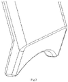
Fig. 3 is a schematic illustration of a crescent type recess of the transverse process retractor and the facet joint retractor. - The technical solution of the present invention will be described in details hereinafter, but the protection scope of the present invention is not limited to the embodiment.
- Embodiment 1: as shown in
Fig. 1 and Fig. 2 , an exposure apparatus for posterior spinal minimally invasive screw placement surgery includes a transverse process retractor and a facet joint retractor used cooperatively with the transverse process retractor. - The transverse process retractor consists of a
first handle 1 and afirst retractor body 2, wherein thefirst retractor body 2 is an L-shaped metal bar having an included angle of 100 degrees, one end of thefirst retractor body 2 is fixedly connected to thefirst handle 1, the other end of the first retractor bends towards the direction of thefirst handle 1, and the end is provided with a crescent type recess. - The facet joint retractor consists of a
second handle 3 and asecond retractor body 4, wherein thesecond retractor body 4 is an L-shaped metal bar having an included angle of 80 degrees, one end of thesecond retractor body 4 is fixedly connected to thesecond handle 3, the other end of the second retractor body bends towards the direction of thesecond handle 3, and the end is provided with a crescent type recess. - Both the
first retractor body 2 and thesecond retractor body 4 include a horizontal segment and a vertical segment, wherein a angle of 165 degrees is formed between the horizontal segment of thefirst handle 1 and thesecond handle 3, both thefirst handle 1 and thesecond handle 3 are located at one side of the horizontal segment opposite to the vertical segment, the other ends of thefirst retractor body 2 and thesecond retractor body 4 respectively bend by 10 ± 10 degrees towards the directions of thefirst handle 1 and thesecond handle 3 respectively, and both the bending lengths of the first retractor body and the second retractor body are 5 ± 3mm. - Both the connected ends of the
first handle 1 and thesecond handle 3 are fishmouth shaped flat structures, both the lengths of thefirst handle 1 and thesecond handle 3 are 120mm, wherein the length of the holding portion is 100mm, both the firs handle and the second handle are circular columns having a diameter of 20mm, and the outer surfaces of the holding portions of thefirst handle 1 and thesecond handle 3 are subject to roughened treatment. Both the thicknesses of thefirst retractor body 2 and thesecond retractor body 4 are 2mm, and the widths thereof are both 12mm; and both the lengths of the horizontal segments of thefirst retractor body 2 and thesecond retractor body 4 are 1 00mm. The length of the vertical segment of thefirst retractor body 2 is 60 or 75mm; and the length of the vertical segment of thesecond retractor body 4 is 50 or 65mm. - The outside of the vertical segment of the transverse process retractor is provided with a
prompt line 5 for prompting a needle inlet point and direction for placing a pedicle screw. - As described above, although the present invention has been represented and described with reference to specifically preferred embodiment, it cannot be interpreted as a limitation to the present invention itself. Various modifications in forms and details may be made thereto without departing from the scope of the present invention as set forth in the appended claims.
Claims (3)
- An exposure apparatus for posterior spinal minimally invasive screw placement surgery, comprising: a transverse process retractor and a facet joint retractor used cooperatively with the transverse process retractor, wherein the transverse process retractor consists of a first handle (1) and a first retractor body (2), the first retractor body (2) is an L-shaped metal bar having an angle of 100 ± 10 degrees, one end of the first retractor body (2) is fixedly connected to the distal end of the first handle (1), the other, distal end of the first retractor bends towards the direction of the first handle (1), and the distal end is provided with a crescent type recess; the facet joint retractor consists of a second handle (3) and a second retractor body (4), the second retractor body (4) is an L-shaped metal bar having an angle of 80 ± 10 degrees, one end of the second retractor body (4) is fixedly connected to the distal end of the second handle (3), the other, distal end of the second retractor body (4) bends towards the direction of the second handle (3), and the end is provided with a crescent type recess; wherein
both the first retractor body (2) and the second retractor body (4) comprise a horizontal segment and a vertical segment, wherein an angle of 165 ± 15 degrees is formed between each of the first handle (1) and the second handle (3) and their corresponding horizontal segments thereof, both the first handle (1) and the second handle (3) are located at one side of the horizontal segment opposite to the vertical segment thereof, the other distal ends of the first retractor body (2) and the second retractor body (4) bend by 10 ± 10 degrees towards the directions of the first handle (1) and the second handle (3) respectively, and both the bending lengths of the first retractor body (2) and the second retractor body (4) are 5 ± 3mm; wherein
both distal ends of the first handle (1) and the second handle (3), which are each respectively connected to the first retractor body (2) and second retractor body (4), are fishmouth shaped flat structures, both the thicknesses of the first retractor body (2) and the second retractor body (4) are 2 ± 1mm, and the widths thereof are both 12 ± 5mm; and both the lengths of the horizontal segments of the first retractor body (2) and the second retractor body (4) are 100 ± 50mm; and wherein the outside of the vertical segment of the transverse process retractor is provided with a prompt line (5) for prompting a needle inlet point and direction for placing a pedicle screw. - The exposure apparatus for posterior spinal minimally invasive screw placement surgery according to claim 1, characterized in that, the length of the vertical segment of the first retractor body (2) is 60 ± 10 or 75 ± 5mm; and the length of the vertical segment of the second retractor body (4) is 50 ± 10 or 65 ± 5mm.
- The exposure apparatus for posterior spinal minimally invasive screw placement surgery according to claim 1, characterized in that, the outer surfaces of the holding portions of the first handle (1) and the second handle (3) are subject to roughened treatment.
Applications Claiming Priority (2)
| Application Number | Priority Date | Filing Date | Title |
|---|---|---|---|
| CN201310035400.1A CN103110437B (en) | 2013-01-30 | 2013-01-30 | Exposure device for spinal posterior minimally invasive surgery nailing |
| PCT/CN2013/087037 WO2014117562A1 (en) | 2013-01-30 | 2013-11-13 | Exposure apparatus for spinal posterior minimally invasive screw fixation surgery |
Publications (3)
| Publication Number | Publication Date |
|---|---|
| EP2952139A1 EP2952139A1 (en) | 2015-12-09 |
| EP2952139A4 EP2952139A4 (en) | 2016-12-07 |
| EP2952139B1 true EP2952139B1 (en) | 2018-04-18 |
Family
ID=54361245
Family Applications (1)
| Application Number | Title | Priority Date | Filing Date |
|---|---|---|---|
| EP13873354.8A Not-in-force EP2952139B1 (en) | 2013-01-30 | 2013-11-13 | Exposure apparatus for spinal posterior minimally invasive screw fixation surgery |
Country Status (5)
| Country | Link |
|---|---|
| US (1) | US9439641B2 (en) |
| EP (1) | EP2952139B1 (en) |
| CN (2) | CN103110437B (en) |
| ES (1) | ES2673146T3 (en) |
| WO (1) | WO2014117562A1 (en) |
Families Citing this family (15)
| Publication number | Priority date | Publication date | Assignee | Title |
|---|---|---|---|---|
| CN103110437B (en) * | 2013-01-30 | 2015-02-11 | 南京医科大学第一附属医院 | Exposure device for spinal posterior minimally invasive surgery nailing |
| CN203059800U (en) * | 2013-01-30 | 2013-07-17 | 南京医科大学第一附属医院 | Exposure apparatus for spinal posterior small incision paravertebral muscle clearance approach |
| CN106264629A (en) * | 2016-11-04 | 2017-01-04 | 山东大学第二医院 | Scope skull base surgery drag hook and method |
| CN106667535A (en) * | 2016-12-02 | 2017-05-17 | 彭国光 | Mandibular rumas hook |
| US20240260852A1 (en) * | 2023-02-08 | 2024-08-08 | Apex Orthopedics, LLC | Instrumentation, Devices, and Methods for Treating Mid-Foot Orthopedic Disorders |
| CN107638199B (en) * | 2017-10-24 | 2024-05-31 | 浙江科惠医疗器械股份有限公司 | Lumbar vertebra side road minimally invasive exposure auxiliary assembly |
| CN107802329B (en) * | 2017-11-21 | 2024-02-13 | 中国人民解放军第四五五医院 | Spinal puncture positioning aid |
| FR3086159B1 (en) * | 2018-09-21 | 2021-07-23 | Allyon | SOFT TISSUE SPREADING TOOL COVERING LUMBAR VERTEBRA |
| CN109330648B (en) * | 2018-11-22 | 2021-06-29 | 南昌大学第二附属医院 | Anterior cervical traction device and system |
| CN112353439A (en) * | 2020-11-26 | 2021-02-12 | 哈尔滨医科大学 | Muscle spreader suitable for spine Wiltse approach operation |
| CN112656462A (en) * | 2020-12-25 | 2021-04-16 | 河北医科大学第三医院 | Pelvis operation retractor |
| EP4162883A1 (en) | 2021-10-06 | 2023-04-12 | K2M, Inc. | Offset hohmann |
| CN113974720B (en) * | 2021-11-09 | 2023-06-23 | 西安市红会医院 | A surgical instrument used to expose the acetabulum |
| US20240293113A1 (en) * | 2023-03-03 | 2024-09-05 | Foot Innovations, Llc | Retractor device |
| US20250160809A1 (en) * | 2023-11-21 | 2025-05-22 | Nicholas J. Schoch | Surgical retractor device and method of use |
Family Cites Families (16)
| Publication number | Priority date | Publication date | Assignee | Title |
|---|---|---|---|---|
| US4817587A (en) * | 1987-08-31 | 1989-04-04 | Janese Woodrow W | Ring para-spinal retractor |
| DE3736066C1 (en) * | 1987-10-24 | 1988-11-10 | Aesculap Werke Ag | Retractor |
| US5944658A (en) * | 1997-09-23 | 1999-08-31 | Koros; Tibor B. | Lumbar spinal fusion retractor and distractor system |
| CN2383475Y (en) * | 1999-07-15 | 2000-06-21 | 郝振海 | Retractor for vertebral lamina |
| JP2005506098A (en) * | 2001-01-29 | 2005-03-03 | デピュイ スパイン、インコーポレイテッド | Spinal pedicle screw placement retractor and method |
| CN2618567Y (en) * | 2003-05-16 | 2004-06-02 | 天津医科大学总医院 | Micro trauma spinal nerve specific hook |
| US7455639B2 (en) * | 2004-09-20 | 2008-11-25 | Stephen Ritland | Opposing parallel bladed retractor and method of use |
| CN2910132Y (en) * | 2006-05-17 | 2007-06-13 | 傅一山 | Retractor for microwound spine |
| CN201290705Y (en) * | 2008-11-28 | 2009-08-19 | 上海市第一人民医院 | Holding type art transverse process draw-hook |
| US8083780B2 (en) * | 2009-04-23 | 2011-12-27 | Custom Spine, Inc. | Spinal fixation mechanism |
| EP2490598A1 (en) | 2009-10-21 | 2012-08-29 | Thompson Surgical Instruments, Inc. | Retractor system for anterior cervical spine surgery |
| CN201537102U (en) * | 2009-11-25 | 2010-08-04 | 黄志海 | Forked hollow vertebral plate draw hook |
| EP2654822A4 (en) * | 2010-04-07 | 2015-07-29 | Clifford T Solomon | Surgical implements with suction and irrigation passages |
| CN102166125B (en) * | 2011-04-23 | 2012-11-14 | 浙江大学 | Set of appliances for posterior lumbar interbody minimally invasive fusion |
| WO2012159088A1 (en) * | 2011-05-18 | 2012-11-22 | Automated Medical Products Corporation | Telescoping surgical support and retractor system |
| CN103110437B (en) * | 2013-01-30 | 2015-02-11 | 南京医科大学第一附属医院 | Exposure device for spinal posterior minimally invasive surgery nailing |
-
2013
- 2013-01-30 CN CN201310035400.1A patent/CN103110437B/en active Active
- 2013-01-30 CN CN2013200514665U patent/CN203059799U/en not_active Expired - Fee Related
- 2013-11-13 ES ES13873354.8T patent/ES2673146T3/en active Active
- 2013-11-13 WO PCT/CN2013/087037 patent/WO2014117562A1/en not_active Ceased
- 2013-11-13 US US14/764,797 patent/US9439641B2/en not_active Expired - Fee Related
- 2013-11-13 EP EP13873354.8A patent/EP2952139B1/en not_active Not-in-force
Non-Patent Citations (1)
| Title |
|---|
| None * |
Also Published As
| Publication number | Publication date |
|---|---|
| CN103110437B (en) | 2015-02-11 |
| EP2952139A4 (en) | 2016-12-07 |
| WO2014117562A1 (en) | 2014-08-07 |
| EP2952139A1 (en) | 2015-12-09 |
| CN203059799U (en) | 2013-07-17 |
| ES2673146T3 (en) | 2018-06-20 |
| CN103110437A (en) | 2013-05-22 |
| US20150366549A1 (en) | 2015-12-24 |
| US9439641B2 (en) | 2016-09-13 |
Similar Documents
| Publication | Publication Date | Title |
|---|---|---|
| US9439641B2 (en) | Exposure apparatus for posterior spinal minimally invasive screw placement surgery | |
| EP2952140B1 (en) | Exposure apparatus for paraspinal muscle clearance approach with posteriorspinal small incision | |
| JP7582918B2 (en) | Bone Positioning Guide | |
| CN103110454B (en) | Guide device for spinal posterior ray-free screw fixation | |
| US8167908B2 (en) | Polyaxial transverse connector | |
| US9351752B2 (en) | Insertion tool for a spinal cord stimulation electrode | |
| US20130046347A1 (en) | Bendable bone plate for external fixation | |
| CN106999210B (en) | Surgical tools with positioning components | |
| BR102014025022B1 (en) | REDUCTION FORCEPS | |
| WO2015007235A1 (en) | Intradermal positioning apparatus for lumbar vertebra minimally invasive surgery | |
| CN103263289B (en) | Screw-implanting sighting device used for minimally invasive surgery | |
| JP2021151524A (en) | Treatment instrument | |
| CN203252720U (en) | Nail entrance navigation device | |
| CN204995572U (en) | Dentata gorge portion fracture individuation pulling force screw navigation template | |
| TW202342122A (en) | Guide device for percutaneous puncture of spine capable of accurately guiding the bone puncture needle to reach the target vertebrae to be treated, thereby improving the stability and accuracy of drilling during spinal surgery | |
| JP2008272146A (en) | Steel wire for distal radius bone fracture | |
| CN203059916U (en) | Vertebral pedicle positioner for spinal posterior minimally invasive nailing | |
| RU2621871C1 (en) | Method for front floating sternocostal valve fixation in case of bilateral rib fractures | |
| CN203315064U (en) | Iliolumbar joint | |
| RU2568534C1 (en) | Method for surgical management of lumbar scoliosis | |
| CN209474687U (en) | Lateral mass of atlas positions nerve dissector | |
| CN103381105A (en) | Lumbosacral portion and ilium combined device and method for combined fixation to lumbosacral portion and ilium through adopting same | |
| Ji et al. | Design of Medium Contact 3D Printed Guides in Robot-Assisted Laminectomy: Finite Element Analysis and Animal Experiment | |
| JP7383683B2 (en) | Systems and methods for the treatment and osteotomy of rib fractures using implants | |
| WO2014117560A1 (en) | Vertebral arch pedicle positioner for spinal posterior minimally invasive screw fixation |
Legal Events
| Date | Code | Title | Description |
|---|---|---|---|
| PUAI | Public reference made under article 153(3) epc to a published international application that has entered the european phase |
Free format text: ORIGINAL CODE: 0009012 |
|
| 17P | Request for examination filed |
Effective date: 20150730 |
|
| AK | Designated contracting states |
Kind code of ref document: A1 Designated state(s): AL AT BE BG CH CY CZ DE DK EE ES FI FR GB GR HR HU IE IS IT LI LT LU LV MC MK MT NL NO PL PT RO RS SE SI SK SM TR |
|
| AX | Request for extension of the european patent |
Extension state: BA ME |
|
| DAX | Request for extension of the european patent (deleted) | ||
| A4 | Supplementary search report drawn up and despatched |
Effective date: 20161107 |
|
| RIC1 | Information provided on ipc code assigned before grant |
Ipc: A61B 17/02 20060101AFI20161031BHEP |
|
| RIN1 | Information on inventor provided before grant (corrected) |
Inventor name: DAWEI, GE Inventor name: LI, HAIJUN Inventor name: TANG, JIAN Inventor name: XIE, HAO Inventor name: TAO, SUI Inventor name: LEI, YANG Inventor name: CAO, XIAOJIAN |
|
| GRAP | Despatch of communication of intention to grant a patent |
Free format text: ORIGINAL CODE: EPIDOSNIGR1 |
|
| INTG | Intention to grant announced |
Effective date: 20171107 |
|
| GRAS | Grant fee paid |
Free format text: ORIGINAL CODE: EPIDOSNIGR3 |
|
| GRAA | (expected) grant |
Free format text: ORIGINAL CODE: 0009210 |
|
| AK | Designated contracting states |
Kind code of ref document: B1 Designated state(s): AL AT BE BG CH CY CZ DE DK EE ES FI FR GB GR HR HU IE IS IT LI LT LU LV MC MK MT NL NO PL PT RO RS SE SI SK SM TR |
|
| REG | Reference to a national code |
Ref country code: GB Ref legal event code: FG4D |
|
| REG | Reference to a national code |
Ref country code: CH Ref legal event code: EP |
|
| REG | Reference to a national code |
Ref country code: AT Ref legal event code: REF Ref document number: 989555 Country of ref document: AT Kind code of ref document: T Effective date: 20180515 |
|
| REG | Reference to a national code |
Ref country code: IE Ref legal event code: FG4D |
|
| REG | Reference to a national code |
Ref country code: DE Ref legal event code: R096 Ref document number: 602013036277 Country of ref document: DE |
|
| REG | Reference to a national code |
Ref country code: ES Ref legal event code: FG2A Ref document number: 2673146 Country of ref document: ES Kind code of ref document: T3 Effective date: 20180620 |
|
| REG | Reference to a national code |
Ref country code: NL Ref legal event code: MP Effective date: 20180418 |
|
| REG | Reference to a national code |
Ref country code: LT Ref legal event code: MG4D |
|
| PG25 | Lapsed in a contracting state [announced via postgrant information from national office to epo] |
Ref country code: NL Free format text: LAPSE BECAUSE OF FAILURE TO SUBMIT A TRANSLATION OF THE DESCRIPTION OR TO PAY THE FEE WITHIN THE PRESCRIBED TIME-LIMIT Effective date: 20180418 |
|
| REG | Reference to a national code |
Ref country code: FR Ref legal event code: PLFP Year of fee payment: 6 |
|
| PG25 | Lapsed in a contracting state [announced via postgrant information from national office to epo] |
Ref country code: BG Free format text: LAPSE BECAUSE OF FAILURE TO SUBMIT A TRANSLATION OF THE DESCRIPTION OR TO PAY THE FEE WITHIN THE PRESCRIBED TIME-LIMIT Effective date: 20180718 Ref country code: FI Free format text: LAPSE BECAUSE OF FAILURE TO SUBMIT A TRANSLATION OF THE DESCRIPTION OR TO PAY THE FEE WITHIN THE PRESCRIBED TIME-LIMIT Effective date: 20180418 Ref country code: SE Free format text: LAPSE BECAUSE OF FAILURE TO SUBMIT A TRANSLATION OF THE DESCRIPTION OR TO PAY THE FEE WITHIN THE PRESCRIBED TIME-LIMIT Effective date: 20180418 Ref country code: AL Free format text: LAPSE BECAUSE OF FAILURE TO SUBMIT A TRANSLATION OF THE DESCRIPTION OR TO PAY THE FEE WITHIN THE PRESCRIBED TIME-LIMIT Effective date: 20180418 Ref country code: NO Free format text: LAPSE BECAUSE OF FAILURE TO SUBMIT A TRANSLATION OF THE DESCRIPTION OR TO PAY THE FEE WITHIN THE PRESCRIBED TIME-LIMIT Effective date: 20180718 Ref country code: PL Free format text: LAPSE BECAUSE OF FAILURE TO SUBMIT A TRANSLATION OF THE DESCRIPTION OR TO PAY THE FEE WITHIN THE PRESCRIBED TIME-LIMIT Effective date: 20180418 Ref country code: LT Free format text: LAPSE BECAUSE OF FAILURE TO SUBMIT A TRANSLATION OF THE DESCRIPTION OR TO PAY THE FEE WITHIN THE PRESCRIBED TIME-LIMIT Effective date: 20180418 |
|
| PG25 | Lapsed in a contracting state [announced via postgrant information from national office to epo] |
Ref country code: HR Free format text: LAPSE BECAUSE OF FAILURE TO SUBMIT A TRANSLATION OF THE DESCRIPTION OR TO PAY THE FEE WITHIN THE PRESCRIBED TIME-LIMIT Effective date: 20180418 Ref country code: RS Free format text: LAPSE BECAUSE OF FAILURE TO SUBMIT A TRANSLATION OF THE DESCRIPTION OR TO PAY THE FEE WITHIN THE PRESCRIBED TIME-LIMIT Effective date: 20180418 Ref country code: LV Free format text: LAPSE BECAUSE OF FAILURE TO SUBMIT A TRANSLATION OF THE DESCRIPTION OR TO PAY THE FEE WITHIN THE PRESCRIBED TIME-LIMIT Effective date: 20180418 Ref country code: GR Free format text: LAPSE BECAUSE OF FAILURE TO SUBMIT A TRANSLATION OF THE DESCRIPTION OR TO PAY THE FEE WITHIN THE PRESCRIBED TIME-LIMIT Effective date: 20180719 |
|
| REG | Reference to a national code |
Ref country code: AT Ref legal event code: MK05 Ref document number: 989555 Country of ref document: AT Kind code of ref document: T Effective date: 20180418 |
|
| PG25 | Lapsed in a contracting state [announced via postgrant information from national office to epo] |
Ref country code: PT Free format text: LAPSE BECAUSE OF FAILURE TO SUBMIT A TRANSLATION OF THE DESCRIPTION OR TO PAY THE FEE WITHIN THE PRESCRIBED TIME-LIMIT Effective date: 20180820 |
|
| REG | Reference to a national code |
Ref country code: DE Ref legal event code: R097 Ref document number: 602013036277 Country of ref document: DE |
|
| PG25 | Lapsed in a contracting state [announced via postgrant information from national office to epo] |
Ref country code: SK Free format text: LAPSE BECAUSE OF FAILURE TO SUBMIT A TRANSLATION OF THE DESCRIPTION OR TO PAY THE FEE WITHIN THE PRESCRIBED TIME-LIMIT Effective date: 20180418 Ref country code: CZ Free format text: LAPSE BECAUSE OF FAILURE TO SUBMIT A TRANSLATION OF THE DESCRIPTION OR TO PAY THE FEE WITHIN THE PRESCRIBED TIME-LIMIT Effective date: 20180418 Ref country code: RO Free format text: LAPSE BECAUSE OF FAILURE TO SUBMIT A TRANSLATION OF THE DESCRIPTION OR TO PAY THE FEE WITHIN THE PRESCRIBED TIME-LIMIT Effective date: 20180418 Ref country code: EE Free format text: LAPSE BECAUSE OF FAILURE TO SUBMIT A TRANSLATION OF THE DESCRIPTION OR TO PAY THE FEE WITHIN THE PRESCRIBED TIME-LIMIT Effective date: 20180418 Ref country code: AT Free format text: LAPSE BECAUSE OF FAILURE TO SUBMIT A TRANSLATION OF THE DESCRIPTION OR TO PAY THE FEE WITHIN THE PRESCRIBED TIME-LIMIT Effective date: 20180418 Ref country code: DK Free format text: LAPSE BECAUSE OF FAILURE TO SUBMIT A TRANSLATION OF THE DESCRIPTION OR TO PAY THE FEE WITHIN THE PRESCRIBED TIME-LIMIT Effective date: 20180418 |
|
| PGFP | Annual fee paid to national office [announced via postgrant information from national office to epo] |
Ref country code: DE Payment date: 20181129 Year of fee payment: 6 |
|
| PLBE | No opposition filed within time limit |
Free format text: ORIGINAL CODE: 0009261 |
|
| STAA | Information on the status of an ep patent application or granted ep patent |
Free format text: STATUS: NO OPPOSITION FILED WITHIN TIME LIMIT |
|
| PG25 | Lapsed in a contracting state [announced via postgrant information from national office to epo] |
Ref country code: SM Free format text: LAPSE BECAUSE OF FAILURE TO SUBMIT A TRANSLATION OF THE DESCRIPTION OR TO PAY THE FEE WITHIN THE PRESCRIBED TIME-LIMIT Effective date: 20180418 |
|
| PGFP | Annual fee paid to national office [announced via postgrant information from national office to epo] |
Ref country code: IT Payment date: 20181122 Year of fee payment: 6 Ref country code: FR Payment date: 20181011 Year of fee payment: 6 Ref country code: ES Payment date: 20181203 Year of fee payment: 6 Ref country code: GB Payment date: 20181107 Year of fee payment: 6 |
|
| 26N | No opposition filed |
Effective date: 20190121 |
|
| PG25 | Lapsed in a contracting state [announced via postgrant information from national office to epo] |
Ref country code: SI Free format text: LAPSE BECAUSE OF FAILURE TO SUBMIT A TRANSLATION OF THE DESCRIPTION OR TO PAY THE FEE WITHIN THE PRESCRIBED TIME-LIMIT Effective date: 20180418 |
|
| REG | Reference to a national code |
Ref country code: CH Ref legal event code: PL |
|
| PG25 | Lapsed in a contracting state [announced via postgrant information from national office to epo] |
Ref country code: MC Free format text: LAPSE BECAUSE OF FAILURE TO SUBMIT A TRANSLATION OF THE DESCRIPTION OR TO PAY THE FEE WITHIN THE PRESCRIBED TIME-LIMIT Effective date: 20180418 Ref country code: LU Free format text: LAPSE BECAUSE OF NON-PAYMENT OF DUE FEES Effective date: 20181113 |
|
| REG | Reference to a national code |
Ref country code: BE Ref legal event code: MM Effective date: 20181130 |
|
| REG | Reference to a national code |
Ref country code: IE Ref legal event code: MM4A |
|
| PG25 | Lapsed in a contracting state [announced via postgrant information from national office to epo] |
Ref country code: CH Free format text: LAPSE BECAUSE OF NON-PAYMENT OF DUE FEES Effective date: 20181130 Ref country code: LI Free format text: LAPSE BECAUSE OF NON-PAYMENT OF DUE FEES Effective date: 20181130 |
|
| PG25 | Lapsed in a contracting state [announced via postgrant information from national office to epo] |
Ref country code: IE Free format text: LAPSE BECAUSE OF NON-PAYMENT OF DUE FEES Effective date: 20181113 |
|
| PG25 | Lapsed in a contracting state [announced via postgrant information from national office to epo] |
Ref country code: BE Free format text: LAPSE BECAUSE OF NON-PAYMENT OF DUE FEES Effective date: 20181130 |
|
| PG25 | Lapsed in a contracting state [announced via postgrant information from national office to epo] |
Ref country code: MT Free format text: LAPSE BECAUSE OF NON-PAYMENT OF DUE FEES Effective date: 20181113 |
|
| PG25 | Lapsed in a contracting state [announced via postgrant information from national office to epo] |
Ref country code: TR Free format text: LAPSE BECAUSE OF FAILURE TO SUBMIT A TRANSLATION OF THE DESCRIPTION OR TO PAY THE FEE WITHIN THE PRESCRIBED TIME-LIMIT Effective date: 20180418 |
|
| REG | Reference to a national code |
Ref country code: DE Ref legal event code: R119 Ref document number: 602013036277 Country of ref document: DE |
|
| PG25 | Lapsed in a contracting state [announced via postgrant information from national office to epo] |
Ref country code: CY Free format text: LAPSE BECAUSE OF FAILURE TO SUBMIT A TRANSLATION OF THE DESCRIPTION OR TO PAY THE FEE WITHIN THE PRESCRIBED TIME-LIMIT Effective date: 20180418 Ref country code: MK Free format text: LAPSE BECAUSE OF NON-PAYMENT OF DUE FEES Effective date: 20180418 Ref country code: HU Free format text: LAPSE BECAUSE OF FAILURE TO SUBMIT A TRANSLATION OF THE DESCRIPTION OR TO PAY THE FEE WITHIN THE PRESCRIBED TIME-LIMIT; INVALID AB INITIO Effective date: 20131113 |
|
| PG25 | Lapsed in a contracting state [announced via postgrant information from national office to epo] |
Ref country code: IS Free format text: LAPSE BECAUSE OF FAILURE TO SUBMIT A TRANSLATION OF THE DESCRIPTION OR TO PAY THE FEE WITHIN THE PRESCRIBED TIME-LIMIT Effective date: 20180818 |
|
| GBPC | Gb: european patent ceased through non-payment of renewal fee |
Effective date: 20191113 |
|
| PG25 | Lapsed in a contracting state [announced via postgrant information from national office to epo] |
Ref country code: GB Free format text: LAPSE BECAUSE OF NON-PAYMENT OF DUE FEES Effective date: 20191113 Ref country code: DE Free format text: LAPSE BECAUSE OF NON-PAYMENT OF DUE FEES Effective date: 20200603 Ref country code: FR Free format text: LAPSE BECAUSE OF NON-PAYMENT OF DUE FEES Effective date: 20191130 Ref country code: IT Free format text: LAPSE BECAUSE OF NON-PAYMENT OF DUE FEES Effective date: 20191113 |
|
| REG | Reference to a national code |
Ref country code: ES Ref legal event code: FD2A Effective date: 20210528 |
|
| PG25 | Lapsed in a contracting state [announced via postgrant information from national office to epo] |
Ref country code: ES Free format text: LAPSE BECAUSE OF NON-PAYMENT OF DUE FEES Effective date: 20191114 |