EP2950737B1 - Planification d'un traitement par ultrasons focalisés basés sur la simulation - Google Patents
Planification d'un traitement par ultrasons focalisés basés sur la simulation Download PDFInfo
- Publication number
- EP2950737B1 EP2950737B1 EP14721003.3A EP14721003A EP2950737B1 EP 2950737 B1 EP2950737 B1 EP 2950737B1 EP 14721003 A EP14721003 A EP 14721003A EP 2950737 B1 EP2950737 B1 EP 2950737B1
- Authority
- EP
- European Patent Office
- Prior art keywords
- treatment
- tissue
- ultrasound
- target
- effect
- Prior art date
- Legal status (The legal status is an assumption and is not a legal conclusion. Google has not performed a legal analysis and makes no representation as to the accuracy of the status listed.)
- Active
Links
Images
Classifications
-
- A—HUMAN NECESSITIES
- A61—MEDICAL OR VETERINARY SCIENCE; HYGIENE
- A61B—DIAGNOSIS; SURGERY; IDENTIFICATION
- A61B34/00—Computer-aided surgery; Manipulators or robots specially adapted for use in surgery
- A61B34/10—Computer-aided planning, simulation or modelling of surgical operations
-
- A—HUMAN NECESSITIES
- A61—MEDICAL OR VETERINARY SCIENCE; HYGIENE
- A61N—ELECTROTHERAPY; MAGNETOTHERAPY; RADIATION THERAPY; ULTRASOUND THERAPY
- A61N7/00—Ultrasound therapy
- A61N7/02—Localised ultrasound hyperthermia
-
- A—HUMAN NECESSITIES
- A61—MEDICAL OR VETERINARY SCIENCE; HYGIENE
- A61B—DIAGNOSIS; SURGERY; IDENTIFICATION
- A61B34/00—Computer-aided surgery; Manipulators or robots specially adapted for use in surgery
- A61B34/10—Computer-aided planning, simulation or modelling of surgical operations
- A61B2034/101—Computer-aided simulation of surgical operations
- A61B2034/102—Modelling of surgical devices, implants or prosthesis
- A61B2034/104—Modelling the effect of the tool, e.g. the effect of an implanted prosthesis or for predicting the effect of ablation or burring
-
- A—HUMAN NECESSITIES
- A61—MEDICAL OR VETERINARY SCIENCE; HYGIENE
- A61B—DIAGNOSIS; SURGERY; IDENTIFICATION
- A61B34/00—Computer-aided surgery; Manipulators or robots specially adapted for use in surgery
- A61B34/10—Computer-aided planning, simulation or modelling of surgical operations
- A61B2034/101—Computer-aided simulation of surgical operations
- A61B2034/105—Modelling of the patient, e.g. for ligaments or bones
-
- A—HUMAN NECESSITIES
- A61—MEDICAL OR VETERINARY SCIENCE; HYGIENE
- A61B—DIAGNOSIS; SURGERY; IDENTIFICATION
- A61B90/00—Instruments, implements or accessories specially adapted for surgery or diagnosis and not covered by any of the groups A61B1/00 - A61B50/00, e.g. for luxation treatment or for protecting wound edges
- A61B90/36—Image-producing devices or illumination devices not otherwise provided for
- A61B90/37—Surgical systems with images on a monitor during operation
- A61B2090/374—NMR or MRI
-
- A—HUMAN NECESSITIES
- A61—MEDICAL OR VETERINARY SCIENCE; HYGIENE
- A61B—DIAGNOSIS; SURGERY; IDENTIFICATION
- A61B90/00—Instruments, implements or accessories specially adapted for surgery or diagnosis and not covered by any of the groups A61B1/00 - A61B50/00, e.g. for luxation treatment or for protecting wound edges
- A61B90/36—Image-producing devices or illumination devices not otherwise provided for
- A61B90/37—Surgical systems with images on a monitor during operation
- A61B2090/376—Surgical systems with images on a monitor during operation using X-rays, e.g. fluoroscopy
- A61B2090/3762—Surgical systems with images on a monitor during operation using X-rays, e.g. fluoroscopy using computed tomography systems [CT]
-
- A—HUMAN NECESSITIES
- A61—MEDICAL OR VETERINARY SCIENCE; HYGIENE
- A61N—ELECTROTHERAPY; MAGNETOTHERAPY; RADIATION THERAPY; ULTRASOUND THERAPY
- A61N7/00—Ultrasound therapy
- A61N2007/0086—Beam steering
-
- A—HUMAN NECESSITIES
- A61—MEDICAL OR VETERINARY SCIENCE; HYGIENE
- A61N—ELECTROTHERAPY; MAGNETOTHERAPY; RADIATION THERAPY; ULTRASOUND THERAPY
- A61N7/00—Ultrasound therapy
- A61N2007/0086—Beam steering
- A61N2007/0095—Beam steering by modifying an excitation signal
Definitions
- the present invention relates, generally, to treatment planning for focused-ultrasound procedures. More specifically. various embodiments are directed to computing systems and methods for simulating and adjusting therapeutic procedures prior to execution.
- High-intensity focused ultrasonic energy may be used therapeutically to treat internal tissue regions within a patient.
- ultrasonic waves may be used to induce coagulation and/or necrosis in a target tissue region, such as a tumor. In this process, the ultrasonic energy is absorbed by the tissue, causing the generation of heat.
- Ultrasound can also be used for a variety of other treatment modalities, including, e.g., cavitation induced by ultrasound, neummodulation, or controlled hyperthermia.
- Focused-ultrasound methods may utilize, for example, a piezo-ceramic transducer that is placed externally to the patient but in close proximity to the target.
- the transducer converts an electronic drive signal into mechanical vibrations, resulting in the emission of acoustic waves (a process hereinafter referred to as "sonication"),
- the transducer may be shaped so that the waves converge in a focal zone, Further, the transducer is typically defined by a plurality of individually driven transducer elements whose phases and amplitudes can each be controlled independently from one another and, thus, can be set so as to result in constructive interference of the individual acoustic waves in the focal zone.
- Such a "phased-array" transducer facilitates steering the focal zone to different locations by adjusting the relative phases between the transducer elements.
- Focused-ultrasound treatment procedures typically require moving the focus across the target to cover the treatment area or volume, which is generally larger than the focal zone, in a series of sonications. In doing so, it is important to apply a sufficient amount of energy across the target to achieve the desired therapeutic effect while limiting accumulated energy levels in surrounding non-target tissues to avoid damage thereto. This requires detailed knowledge of the patient's anatomy in the region surrounding the target, as may be acquired, e.g., by magnetic resonance imaging (MRI). Further, it requires computational facilities to determine accurate and precise phase and amplitude settings for the individual transducer elements to focus the beam at the desired places.
- MRI magnetic resonance imaging
- anatomical barriers such as tissues that do not transmit or are highly sensitive to ultrasound, are located between the transducer array and the target, requiring the transducer to be either moved or driven with fewer than all elements, which further complicates the procedure.
- therapeutic procedures often reach a level of complexity that requires detailed advance planning to determine, based on the anticipated relative arrangement between the patient and the transducer, the phase and amplitude settings of all transducer elements as a function of time.
- Conventional treatment-planning methods typically utilize a limited number of predefined sonication protocols corresponding to differently shaped focal zones, and involve “tiling" the treatment region with these shapes. Such methods, however, usually fail to account for the accumulated effect of overlapping "tiles," ultrasound absorption outside the focal zone, as well as heat transfer from the focal zone into surrounding areas.
- a conventional treatment planner might slice the volume into a series of adjacent two-dimensional slices, cover each slice by a number of predefined sonications, and compute the energy for each sonication based on the desired dose in the respective slice.
- each slice absorbs energy not only from sonications focused at the slice, but also from sonications directed at neighboring slices. Consequently, the total amount of energy deposited in the slice may exceed that previously calculated. While such excessive heating may not have a detrimental effect for treatment of the target itself (e.g., because the desired treatment effect is target ablation), it may cause surrounding non-target tissues to be exposed to an unnecessarily high amount of ultrasound energy. Accordingly, it is desirable to add up all contributions to the heating of any region in order to set the energy delivered per sonication to a level no larger than necessary to effect treatment.
- a previously planned treatment procedure can be corrected during treatment based on real-time information about the treatment effect.
- MRI for example, is not only useful to visualize the focus and/or target in order to guide the ultrasound beam, but can also be employed in various thermometry techniques to monitor the temperature distribution in a region including the target to ensure that it remains at a desired level or within a desired range (e.g., above an efficacy threshold in the target region and below a safety threshold in non-target tissues). If the temperature in the target is too low, additional sonications may be applied to reach the desired efficacy threshold.
- a waiting period may be introduced to allow the tissue to cool off.
- irreversible damage may already have been done following absorption of too much energy by a non-target tissue.
- any adjustments to the sonication procedure during treatment based on a measured effect result in prolongation of the overall treatment time, which may not only strain the patient's patience, but also introduce errors, e.g., due to inadvertent but inevitable patient movements.
- US 2010/179425 A1 discloses that the emission intensities of transducer elements of an ultrasound transducer array can be controlled based on anatomical characteristics of non-uniform tissue regions, e.g., regions of a skull, and a pre-determined threshold.
- the intensity of ultrasound energy emitted by each transducer element may be determined or controlled based on previously determined anatomical characteristics and a maximum or threshold skull or skull region temperature.
- a thermo-acoustic simulation may be included.
- thermo-acoustic simulation can involve analyzing an acoustic path through a skull region, performing thermal simulations to estimate how different skull regions absorb different quantities of energy and have different heating profiles, determining the optimal intensity of energy to be emitted by each transducer element, and generating an intensity map corresponding to transducer elements.
- the resulting intensity map includes optimal intensity values of energy emitted by respective individual transducer elements, which collectively optimize the energy delivered to a target region while satisfying one or more temperature thresholds or safety criteria as described above.
- US 2009/0318804 A1 relates to devices and methods for planning and supervising minimally invasive surgery. Included are enhancement to systems for planning, monitoring, and controlling cryosurgery.
- Examples of the present disclosure are directed to treatment-planning methods that involve simulating the planned procedure computationally and, typically, adjusting the procedure iteratively based on the simulated effect, as well as to hardware and/or software for implementing such methods (hereinafter collectively referred to as the "treatment planner” or “planner”).
- the treatment procedure involves multiple treatment methods: for example, an ultrasound procedure may include sonications applied to achieve the therapeutic effect in the target tissue and, complementary thereto, active cooling of tissue surfaces to protect non-target tissues.
- RF radio-frequency
- the simulation generally includes modeling a tissue region of interest and a treatment configuration, computationally applying treatment stimuli, and computationally predicting the effect of the stimuli, typically as a function time.
- the tissue region includes the target and, typically, non-larget tissues - e.g., tissues surrounding the target and/or tissues located, in the case of ultrasound stimuli, between the transducer and the target
- the treatment configuration specifies the geometry as well as the position and orientation of the transducer (or other treatment device) relative to the target.
- the stimuli may include, e.g., a series of sonications at desired focus locations or along a desired focus path and, optionally, thermal stimuli conductively applied to tissue interfaces (e.g., via physical contact thereat with a cooling pad or fluid conduct). Stimuli may also be chemical in nature, e.g., in the case of drug activation or release.
- Predicting the effect of the stimuli generally includes modeling the propagation of a locally induced effect through the tissue region (or a
- the stimuli and treatment effect may be characterized by various physical, biophysical, or biochemical parameters, depending on the particular treatment modality and the desired precision and resolution of the simulation.
- a series of sonication pulses applied at discrete foci may be described in terms of the total energies delivered to the focal locations, or, for greater spatio-temporal resolution, in terms of the intensity distributions within the focal zones over the pulse duration.
- a continuous sonication applied along a focus path across the target may be described in terms of the power and/or intensity of the sonication as a function of time and/or position along the path.
- Active cooling may be captured by specifying the temperature at boundaries in contact with cooling reservoirs.
- the stimuli and/or treatment effect may be described in terms of pressures, forces, a mechanical index, or mechanical stresses.
- the treatment effect may be captured with suitable chemical or biological parameters.
- drug delivery may be described in terms of local concentrations of the drug.
- suitable parameters used to characterize and quantify the stimuli and/or treatment effect may be selected based on the treatment modality.
- ultrasound-based treatment modalities include, without limitation, cavitation (which can have several effects on the surrounding tissue, including, e.g., opening physiological barriers such as the blood brain barrier), neuromodulation (e.g., neurological stimulation or neurological inhibition), targeted drug delivery (e.g., via activation of drugs or disruption of barriers, such as the blood brain barrier, to increase drug uptake), or the triggering of other chemical or physiological activities (e.g., by causing controlled hyperthermia).
- cavitation which can have several effects on the surrounding tissue, including, e.g., opening physiological barriers such as the blood brain barrier
- neuromodulation e.g., neurological stimulation or neurological inhibition
- targeted drug delivery e.g., via activation of drugs or disruption of barriers, such as the blood brain barrier, to increase drug uptake
- other chemical or physiological activities e.g., by causing controlled hyperthermia
- the computed effect of a simulated treatment procedure is compared against one or more treatment constraints, such as a minimum temperature, power, or energy required in the target tissue to achieve a desired treatment effect (an example of an "efficacy constraint") or a maximum temperature allowed in non-target regions to stay within a safe regime (an example of a "safety constraint”).
- Efficacy constraints may be imposed, e.g., in terms of a minimal temperature, minimal thermal dose, minimal acoustic power, minimal acoustic energy, required acoustic wave pattern, maximal distance from sonication foci, or minimal mechanical index.
- Safety constraints may specify, e.g., a maximal temperature, maximal thermal dose, maximal acoustic power, maximal acoustic energy, allowed or prohibited acoustic wave pattern, minimal distance from sonication foci, maximal mechanical index, minimal distance from an area in which a safety constraint is violated, etc.. If one or more of the constraints are violated during the simulation, the simulated treatment procedure is adjusted. Such adjustment generally takes one of two forms: the treatment plan can either be "rolled back" in accordance with the invention so as to modify previously set treatment parameters, or the existing portions of the procedure are retained but the plan is extended to include further sonications (or other treatment steps), this alternative however not forming part of the present invention.
- suitable modifications to the treatment plan may include a reduction of the energy or intensity of sonications applied to the target, a decrease in the temperature of any active cooling medium, and/or - if the temperature has not yet reached levels where tissue damage occurs, but is dangerously close thereto - the incorporation of a cooling-off period in the treatment plan.
- the treatment plan is simulated and adjusted iteratively until the simulated treatment effect no longer violates any of the treatment constraints.
- the constraints may be relaxed during planning to nonetheless allow for completion of the treatment plan.
- the initial constraints are aspirational and serve to iteratively optimize the plan; when iterative treatment-plan adjustments no longer result in improvements, any constraints that are still violated may be dropped (assuming they are within acceptable absolute levels) and the treatment plan is deemed finalized.
- strict adherence to the treatment constraints is important for patient safety, and if modifications to the treatment plan cannot cure constraint violations, treatment planning is aborted as unsuccessful.
- the treatment may be carried out in accordance with the plan.
- the treatment effect is monitored during treatment (e.g., by means of MRI-based or other types of thermometry) to ensure that it does, indeed, remain within the treatment constraints. If discrepancies between the measured treatment effect and the previously computed treatment effect are discovered, the treatment plan may be modified. Discrepancies may arise, for example, from inaccuracies in certain parameters of the physical model underlying the simulation, such as, e.g., absorption coefficients. Accordingly, the measurements taken during actual treatment may be used as feedback to adjust the parameters. A new treatment plan may then be generated using the adjusted parameters. Alternatively, in various circumstances, a straightforward adjustment of the existing treatment plan may be carried out, e.g., by propagating the adjustment of the parameter(s) through the model.
- the invention relates to a system for planning and executing focused-ultrasound treatment of a target tissue within a tissue region according to claim 1.
- Creating the treatment plan may further include defining parameters of a complementary treatment procedure, such as, e.g., active healing or cooling.
- the physical model may include one or more parameters of the tissue region (e.g., absorption coefficients) and/or one or more equations modeling ultrasound absorption and heat transport in the tissue region.
- Predicting the effect of the simulated treatment may include modeling propagation of the effect to a non-target tissue within the tissue region.
- the above treatment-planning steps are successively carried out for a plurality of subregions of the target tissue; the prediction also involves modeling propagation of the effect into another subregion of the target tissue.
- the treatment effect may be include, e.g..
- treatment constraint(s) may include a tissue-damage threshold, a treatment-efficacy threshold, and/or geometric parameters of heat-sensitive tissues.
- treatment planning and simulation may be repeated for the entire subregion.. Alternatively, in some embodiments, they are repeated for only a portion of the focus pattern, and adjustments to the temporally variable ultrasound stimuli are confined to stimuli to be applied along that portion.
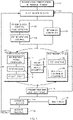
- FIG. 1 illustrates, in the form of a flow chart, an exemplary treatment-planning method in accordance with various embodiments. As shown, treatment planning may begin, in step 100, with providing a visual representation of the patient's anatomy within a region of interest to the treating physician.
- the visual representation may, for example, include or consist of a series of image slices acquired with MRI, computed tomography (CT), ultrasound, or any other medical imaging modality, or a three-dimensional graphical model created based on such images.
- CT computed tomography
- the physician identifies a target, or portion of a target, within the region of interest, e.g., by overlaying an outline around the organ to be treated on the image (or a series of images).
- Such an outline may be directly drawn by the physician using a suitable drawing interface (e.g., a touch screen that allows the physician to trace the organ boundaries in the image with her finger or a suitable stylist), or be computer-generated, based on a physician-made selection (e.g., clicking on the target organ), using image-segmentation or other suitable image-processing techniques.
- a suitable drawing interface e.g., a touch screen that allows the physician to trace the organ boundaries in the image with her finger or a suitable stylist
- a physician-made selection e.g., clicking on the target organ
- Treatment planning is performed sequentially for multiple individual regions that collectively constitute the overall target, and the physician may, in step 102, select the region for which treatment is to be planned next.
- the target consists of multiple discontiguous regions; for example, a cancer patient may be afflicted with multiple tumors or metastases that are to be treated individually. Even if the target is a single, contiguous tissue region, it may be divided, for planning and/or treatment purposes, into multiple (disjunctive or overlapping) regions.
- a three-dimensional target volume in slices which may provide better control over beam properties despite tissue heterogeneities in the target resulting from treatment (e.g., to avoid beam aberrations, the slice most distant from the transducer may be treated first), allow covering the target volume with minimal mechanical maneuvering (e.g., minimal adjustments to the position and orientation of the transducer during treatment), and facilitate monitoring treatment of each slice without requiring any change of the imaging plane.
- the target is divided in a manner that allows treatment planning for the different regions to be performed sequentially, taking the effect of treatment of one region into account when planning treatment for subsequent regions, but without incurring the risk of a need to revisit a treatment procedure for a region for which treatment planning was previously deemed complete.
- a focus pattern that covers the region may be fitted to the region (step 104).
- the treatment planner may fit a grid of focal points to the region such that focal zones located at the grid points collectively cover the region (with or without overlap between the zones).
- a focal zone may defined as a contiguous region around a focus point that is bounded by a fall-off in the intensity to half, or some other specified fraction, of the maximum intensity.
- the region may be adequately covered with a two-dimensional distribution of focal points; in general, however, the grid of focal points is three-dimensional.
- the focus pattern includes, instead of a set of discrete focus locations, one or more continuous focus paths within the target; in this case, treatment involves moving the ultrasound focus along the path(s) (again, in the case of multiple path segments, in an order specified during planning) and thereby sweeping the focal zone across the target.
- the focal paths may be configured, in two or three dimensions, such that the focal zone has covered the entire (or substantially entire) region once all paths have been traversed.
- the locations of the focal points and/or paths may be computed taking into account the patient's overall anatomy, the shapes and locations of the target and any relevant non-target organs or tissues, and/or the transducer location.
- the focus pattern is generally determined autonomously by the planner using suitable algorithms, it may, in some embodiments, be adjusted based on physician input. For example, the physician may, based on his experience, manually tweak the density of grid points or paths in certain subregions.
- the focal spot created by an individual focused beam is too small to be meaningful for clinical and/or simulation purposes.
- a group of (e.g., on the order of ten) foci arranged in a fixed pattern in the vicinity of a grid point and collectively forming a contiguous zone may be treated collectively as one focus at the grid point with a corresponding focal zone; the individual foci are then referred to as "sub-foci.”
- the focal zone at a grid point may be created by sequentially focusing the beam, or simultaneously focusing multiple beams (which may, e.g., be created with multiple segments of an ultrasound transducer array), at the plurality of "sub-foci.”
- ultrasound application at a group of sub-foci belonging to the same focal zone is considered a single sonication, and no distinction is made between a sonication created by a single focus and a sonication created by a group of sub-foci
- a treatment efficacy threshold for the region is defined - e.g., in terms of a temperature or thermal dose required to achieve the desired therapeutic effect (such as, e.g., ablation of the target tissue).
- the treatment efficacy threshold may vary depending on position. For example, for focal points far away from sensitive organs, the treatment planner will generally apply more aggressive criteria to assure treatment efficacy.
- Clinical constraints include both inherent anatomical constraints (such as, e.g., ultrasound barriers such as reflective tissues) that affect beam paths, treatment windows, and transducer placement, and treatment constraints that are deliberately imposed to ensure that treatment of the target area is conducted safely, i.e., without causing significant damage to other areas (or, in certain non-destructive treatment modalities, without damaging the target itself).
- inherent anatomical constraints such as, e.g., ultrasound barriers such as reflective tissues
- treatment constraints that are deliberately imposed to ensure that treatment of the target area is conducted safely, i.e., without causing significant damage to other areas (or, in certain non-destructive treatment modalities, without damaging the target itself).
- Such safety-based constraints may, for example, specify maximum pressures, energy densities, heat doses, or temperatures and/or allowable deviations from targeted temperatures, energy doses, etc., and may require avoidance of pressure profiles that might cause, e.g., undesired cavitation or neuromodulation.
- the target tissue itself may also be subject to safety-based constraints, e.g., to avoid boiling of the target.
- safety thresholds and constraints may be defined separately for each tissue type.
- constraints may be extended from a sensitive organ or tissue itself into the surrounding area to provide a spatial safety margin; for example, a thermal dose exceeding a specified threshold amount may not be allowed within a specific distance of a sensitive tissue.
- Clinical constraints may be defined by the treatment planner based on pre-programmed criteria and data, manually set by the physician, or determined by the treatment planner based on physician input.
- the temperature in the treatment target needs to be controlled between lower and upper boundaries, which can be set in an analogous manner as described above; here, the lower boundary corresponds to the satisfying coverage (i.e., the minimum energy that needs to be applied to achieve a treatment effect) and the upper boundary corresponds to a safety constraint.
- coverage i.e., the minimum energy that needs to be applied to achieve a treatment effect
- upper boundary corresponds to a safety constraint.
- upper and lower boundaries in hyperthermia treatment generally apply both to the same region, i.e., the target. Consequently, the lower boundary in hypothermia is below the upper boundary, whereas for tissue ablation, the upper boundary applied to non-target tissues may be lower than the lower boundary applied to target tissue.
- constraints may be imposed depending, in general, on the particular treatment modality and application.
- constraints may be imposed on the number or density of bubbles generated in the tissue, the properties of the bubbles, and/or the mechanical index affected thereby.
- constraints may preclude particular focal patterns or family of patterns for certain regions of the brain, if ultrasound simulation along such patterns would induce an undesirable neurological response.
- the treatment planner determines treatment profile parameters for the sonications at each focal point, i.e., at each discrete focus or at each point (with a given spatial resolution) along a continuous focus path.
- the treatment profile may include parameters characterizing sonication performance, such as sonication power, acoustic field shape, or the length of the sonication, as well as parameters characterizing the transducer settings for each sonication, such as transducer position and/or orientation and phase and/or amplitude settings for individual transducer elements.
- the treatment profile parameters may be functions of both the focal position and the treatment stage or time during treatment (as the same spatial focus position may be reached at different times during treatment), and depend on the target location and clinical constraints.
- the planner typically determines the treatment profile parameters iteratively (beginning with initialized parameter settings), using simulations of the treatment and its effect to adjust the parameters in successive iterations. For example, in embodiments utilizing a grid of focal points, the planner traverses, as shown, the grid of focal points according to some predefined logic (step 110), and, for each point traversed, set treatment profile parameters (step 112). An ultrasound stimulus is then computationally applied in accordance with the set parameters (step 114), and the effect of the stimulus (step 116) is computationally predicted.
- an overall treatment plan may be gradually built up from sonications at the individual focal points. More generally, the planner computationally traverses the focus pattern and applies ultrasound stimuli along the way in accordance with current parameter settings. Treatment planning may also include specifying parameters not related to a specific focal point, such as, e.g., waiting time periods during which no sonication takes place.
- the ultrasound treatment procedure is complemented by another treatment modality, such as active cooling (or heating) using, e.g., flow of a cooling fluid through tubing in contact with the skin or another accessible tissue surface or interface.
- treatment planning may further involve setting parameters of the complementary treatment modality, e.g., the temperature and/or flow rate of the cooling fluid.
- computation of the treatment effect takes the complementary modality into account such that the joint effect of, e.g., ultrasound application and active cooling is simulated.
- Other treatment modalities that may complement ultrasound treatment include, e.g., controlled release of a drug or contrast agent, controlled ventilation, controlled anesthesia, or controlled visual stimuli presented, e.g., on a screen to provide instructions, cognitive tasks, or entertainment to the patient. All of these procedures may have an effect on the treatment and may, therefore, be accounted for in the model (which may, in this case, go beyond a physical model and include, e.g., psychological mechanisms). For example, a video shown to the patient may reduce (or, alternatively, ask the patient to impose) motion. Videos and other visual stimuli can also cause activity in neural networks (and blood flow), which is generally relevant to models related to neuromodulation. Controlled drug release is important for modelling targeted drug delivery and blood brain barrier disruption.
- Ultrasonic contrast agents generally interact with the acoustic beam and may change the effect of the beam.
- a ventilator may change the anatomical configuration in areas that are affected by the respiratory cycle.
- Anesthesia may change clinical constraints as it can potentially make the patient more tolerant, e.g., to decreased or increased tissue temperatures.
- the simulation of the sonications (or other treatment stimuli) and their effect on the tissue is, in various embodiments, based on a parameterized physical model.
- the physical model may include volumetric distributions of certain material properties or other physical quantities, such as, e.g., the speed of sound, or tissue coefficients characterizing acoustic absorption, transmission, and impedance; the values of these distributions may vary spatially depending on tissue type, temperature, the patient's oxygen saturation level, or other environmental conditions.
- the physical model may include one or more equations that describe the absorption of ultrasound in the tissue; the conversion of ultrasound energy or pressure into heat, tissue displacement, or other effects; and/or the propagation of the induced effect through the tissue. Typically, these equations take the form of differential equations; examples include diffusion and heat equations.
- a bioheat equation is used to simulate heat transport from a focal zone into the surrounding tissue via convection through the blood stream and/or conduction.
- the Pennes model of heat transfer in perfused tissue, or a modification thereof, may be employed.
- the tissue parameters can, for many practical applications, be assumed to be uniform throughout the tissue; however, certain parameters, such as the metabolic heat generation rate, may vary as a function of time. In regions spanning multiple types of tissue, the tissue parameters usually vary also spatially.
- the term Q ext may also include the effect of heat sinks (i.e., cooling), as long as the thermal power extracted per unit volume of tissue can be quantified; practically, however, cooling (e.g., applied to the skin) is often more appropriately taken into account via suitable boundary conditions (e.g., a fixed temperature at the skin). Additional modifications to the Pennes equation may be made. For example, for certain applications, metabolic heat generation may be negligible, allowing the equation to be simplified by dropping the term Q m .
- heat sinks i.e., cooling
- suitable boundary conditions e.g., a fixed temperature at the skin
- an experimental model derived from measurements and/or general observations, is used either in lieu of or supplementing a physical model. Measurements may also be used to specify variable parameters in the model. For example, tissue densities or other physiological properties may be discerned from MR images, and temperatures may be determined in discrete places using temperature sensors or across areas and volumes using MR thermometry.
- patient- and treatment-specific information such as patient-specific anatomical models or the locations of ultrasound transducers and cooling equipment in specific therapeutic setups, is used, e.g., to establish boundary conditions for the solution of the model equations.
- step 118 it is tested computationally (step 118) for violation of any constraints, i.e., often for both treatment efficacy and safety.
- any constraints i.e., often for both treatment efficacy and safety.
- control points may depend on the positions of the target and the transducer, the patient's anatomy, the focal-point grid or other focus pattern, and the stage during planning. For example, after a first iteration of treatment planning, a small number of control points may suffice to provide feedback for the next iteration, whereas further refinement after multiple iterations may require more extensive testing - in particular, to ensure that no safety constraint has been violated. On the other hand, once testing confirms that satisfying coverage within a certain area has been achieved, this area may not need to be tested for coverage again after the next iteration.
- the computational "measurements" of the temperature, accumulated thermal dose, or other parameter at various control points provide insight into the efficacy and safety of the present treatment plan. Accordingly, they may be used to adjust the treatment profile parameters (step 124) and thereby refine the plan. For example, if the energy deposited at a certain focal point has not reached the specified efficacy threshold, additional energy may be applied at that focal point, either by correcting the initially set thermal dose upwards, or by adding an additional sonication at the same location. In the former case, execution of the treatment plan will involve only one sonication at the focal point at issue, whereas in the latter case, the treatment procedure itself will involve returning to the focal point at issue after traversing other focal points and/or after some time has passed.
- the planner typically "rolls back" the part of the planned treatment that caused the problem and repeats the treatment planning process for a number of focal points (or, more generally, a portion of the focal path) while reducing the applied thermal doses.
- This possibility of rolling back treatment is a major advantage of detailed treatment planning in accordance herewith prior to actual treatment.
- Detection of the constraint violation serves, in this case, mere damage control - for example, the treatment procedure may be aborted to avoid exacerbating the problem through continued heating.
- the simulation of treatment ahead of time allows for the retroactive correction of a problem detected in one run and, thus, the proactive prevention of the same problem in a subsequent run of the simulation.
- Roll-back may be complete or partial: in some embodiments, once a constraint is violated, the previously determined treatment profile parameters are discarded and the traversal of focal points (step 110) starts over; in other embodiments, only a portion of the treatment plan is rolled back. For example, in one embodiment, the plan is kept by and large as is, except that the energy at one or a few focal points responsible for the constraint violation is reduced, and if subsequent testing reveals that the reduction was insufficient, further reductions are applied.
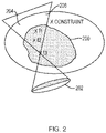
- FIG. 2 which illustrates an exemplary scenario that may require roll-back in treatment planning.
- the shaded area indicates the region 200 to be treated, which includes the three marked focal points f1, f2, and f3.
- a constraint X e.g., a maximum allowable thermal dosage
- the planner may revise the previous sonications.
- the planner reduces the amount of energy focused at f1, re-simulates heat propagation to obtain updated values for the thermal dose accumulated at various control points in the target and non-target regions 200, 206, and continues with the planning, e.g., now adding a sonication at f3 to cover the lower part of the region 200. Going back and forth in treatment time to revise the treatment plan, it is often possible to improve coverage while satisfying safety constraints. Note that reducing the energy at f1, compared to the originally planned amount, does not necessarily compromise coverage in that portion of the target region 200.
- the energy in the originally planned sonication may have been set too high to assure treatment efficacy.
- the residual energy at f1 due to sonications at f2 and f3 may compensate for the decreased amount focused directly at f1. If it is, however, not possible to provide the desired coverage throughout the target region 200 without violating the constraint, f1 is likely the best point to compromise on as it effects the area subject to the constraint the most.
- the planner may routinely leave focal points before achieving satisfying coverage in order to provide a better overall energy distribution; if certain focal points need additional energy after sonication over a larger area has been planned, the planner can return to these focal points.
- treatment planning is, generally, an iterative process that may utilize testing of the simulated treatment plan at various stages.
- the planner need not have traversed the entire grid of focal points before it computationally evaluates coverage and safety of the treatment plan.
- the planner may continue with the next sonication (often basing the treatment profile parameters of subsequent sonications on the results of the test), go back to adjust a previous sonication (or repeat sonication at a previously covered focal point), or even switch the planning to an entirely new region (e.g., return to step 102, which allows the physician to select a region within the target for planning).
- testing may reveal that satisfactory coverage has been achieved for the region to be treated without violating any clinical constraints, and planning for the region is complete.
- the planner may determine that the iterative process is not converging (i.e., adjustments to the treatment plan cannot simultaneously satisfy all treatment constraints ).
- planning for the region may nonetheless be deemed complete if, for instance, the violations are minor (which amounts to relaxing the constraints), or treatment planning may be declared a failure (requiring, e.g., larger manual adjustments to the treatment plan, which may be reviewed by the automatic planner to ensure that the adjusted plan does not violate safety constraints).
- the planner may present the treatment plan to the physician (step 126).
- the presentation may include an image (or series of image slices) of the region and surrounding areas, overlaid with graphics or supplemented with text indicating, e.g., the accumulated thermal dosage or temperature distribution, the transducer position, the order in which focal points are traversed, and/or whether efficacy and safety thresholds are satisfied.
- the physician may modify the plan (step 128), e.g., by changing the treatment order, re-defining treatment constraints, adjusting the treatment energy, or, if necessary, indicating a subregion for which treatment planning is to be repeated.
- the physician finds the treatment plan acceptable he may proceed to select another region for the next planning cycle (step 102), or commence actual treatment of the instant region, i.e., execute the plan (step 130).
- Treatment of a region may be monitored (step 132), e.g., using MRI thermometry or direct temperature sampling with suitably positioned sensors.
- the measured temperature distribution may be compared with the predicted temperature distribution computed by the planner, and any discrepancies may be used to update the treatment plan. Since discrepancies typically arise from uncertainties or inaccuracies in the physical modeling underlying the simulation of the treatment and its effect, measurements taken during treatment are used, in some embodiments, to adjust one or more parameter values of the model(s).
- Adjustments may be made, first, to a parameter, or set of parameters, that has a particularly high uncertainty associated with it (and is therefore likely to need adjustment) and/or a change to which is known to affect the computed treatment effect greatly (i.e., a parameter to which the treatment effect is very sensitive, e.g., because the treatment effect is a higher-order rather than linear function of the parameter).
- a parameter to which the treatment effect is very sensitive e.g., because the treatment effect is a higher-order rather than linear function of the parameter.
- the model parameters are ranked according to their uncertainties and/or the model sensitivity to the parameters to facilitate selection of one or more parameters for adjustment.
- the selected model parameter(s) may be adjusted automatically based on the feedback, e.g., by fitting the model to the measurements.
- fitting is based on measured iso-surfaces corresponding to respective constant temperatures or thermal doses.
- the feedback may inherently encode information about such dependencies, e.g., in the form of spatial or temporal distributions of measured quantities.
- Parameter adjustment may also be based, at least partially, on human input, e.g., as provided by the physician monitoring treatment.
- Such human intervention may be assisted by intuitive visual representations of both predictions and measurements (e.g., in the form of boundaries indicating temperature or thermal-dose iso-surfaces and highlighting efficacy or safety thresholds).
- the displayed prediction may change dynamically in response to any user manipulation of parameter values.
- Parameter adjustments may be bounded by pre-set limits to prevent estimated values that are not physically realistic.
- the adjusted parameters can be propagated through the model to derive an updated treatment plan on the fly, whereas, in other situations, treatment may need to be interrupted to allow time to re-plan treatment of the region.
- treatment plan i.e., an adjustment not requiring complete re-planning
- An example of a straightforward adjustment to the treatment plan is the increase, across all ultrasound stimuli, of the applied power to compensate, e.g., for a smaller absorption coefficient than previously assumed.
- treatment need not be re-planned, but may be completed according to the previously created plan, and the same region may be revisited during the next (or some later) planning cycle to fill in gaps in coverage. Further, if the deviations between the predicted and the measured treatment effect are within a tolerable range, treatment of the currently treated region may continue, while subsequent planning stages for other regions may benefit from the feedback. Whether to continue or interrupt treatment may be decided by the treating physician. The physician may also take feedback into account when selecting the next region to be treated. In various embodiments, the physician deliberately selects regions for planning and treats them one at a time, using treatment results from the previously treated regions as feedback for treatment planning for the next region (e.g., by manually adjusting values of parameters used by the physical model).
- the feedback provided during execution of the treatment plan is not limited to thermal feedback, but may also include acoustic or mechanical feedback, visual feedback (e.g., provided through MRI or another imaging technique), and/or feedback derived from measurements through analysis and calculations (e.g., of the accumulated thermal dose).
- feedback received during treatment may include anatomical information and, importantly, information about any changes relative to the patient's anatomy as it existed at the time treatment was planned. Often, significant changes result from unavoidable patient motion during the treatment.
- Motion-tracking algorithms may be empoyed to detect deformations and positional changes of relevant target or non-target regions, and facilitate adjustments to the treatment plan (e.g., via image-registration algorithms) to compensate for such changes.
- movements and other changes are generally expected to occur during treatment (within certain limits), they may be taken into account by strategically planning the treatment, e.g., by specifying the order in which various regions are treated in a way that expected changes do not substantially increase treatment risk.
- Monitoring the treatment may also involve documenting treatment progress, i.e., generating a treatment history in time.
- the treatment history may include anatomical images and, optionally, indicationsof special regions (e.g., heat-sensitive regions subject to constraints) therein, details of the applied treatment (such as values of planning parameters and/or indications of human interventions), as well as maps of the treatment effect (e.g., thermal maps indicating temperature or accumulated thermal dose).
- the treatment history is continuously adjusted to address any changes along treatment. Such changes may include, for example, tissue deformations and re-locations due to patient motion.
- the treatment history may be annotated with confidence levels indicating the accuracy of the gathered information, and may inform subsequent treatment. For example, it may be used to locate one or more regions that have not received sufficient treatment.
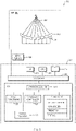
- FIG. 3 schematically illustrates an exemplary system 300 for planning and executing focused ultrasound treatment as described above.
- the system 300 includes an ultrasound transducer 302 comprising a one- or two-dimensional arrangement of transducer elements 304, which may, e.g., be piezoelectric ceramic elements.
- the transducer 302 may be curved (as shown) or planar, and may form a single surface, or include multiple discontiguous and, optionally, independently movable segments.
- the transducer elements 304 may be individually controllable, i.e., each element may be capable of emitting ultrasound waves at amplitudes and/or phases that are independent of the amplitudes and/or phases of the other transducer elements 304.
- the elements 304 may be grouped, and each group may be controlled separately.
- the transducer elements 304 form a "phased array" capable of steering the ultrasound beam in a desired direction, and moving it during a treatment session based on electronic control signals provided by a beam former 306.
- the beam former 306 typically includes electronic control circuitry including amplifier and phase delay circuits for the transducer elements 304. It may split a radio-frequency (RF) input signal, typically in the range from 0.1 MHz to 4 MHz, to provide a plurality of channels for driving the individual transducer elements 304 (or groups thereof) at the same frequency, but at different amplitudes so that they collectively produce a focused ultrasound beam 308.
- RF radio-frequency
- the system 300 may also include other treatment apparatus; for instance, an active heater or cooling device (not shown) with a controllable temperature setting may complement ultrasound treatment by allowing a tissue surface to be held at a desired temperature.
- the system 300 may further include an MRI apparatus 310 (or other imaging device) that allows imaging a region of interest in the patient both prior to treatment for the purpose of treatment planning and during treatment for the purpose of guiding the ultrasound beam and monitoring treatment progress.
- the system 300 includes a computational facility, in communication with the beam former and the MRI apparatus, that facilitates treatment planning and adjustment.
- the computational facility may be implemented in any suitable combination of hardware, software, firmware, or hardwiring; in the illustrated embodiment, it is provided by a suitably programmed general-purpose computer 312.
- the computer may include a central processing unit (CPU) 314 and system memory 316, as well as, typically, one or more non-volatile mass storage devices 318 (such as one or more hard disks and/or optical storage units).
- the computer 312 further includes a bidirectional system bus 320 over which the CPU 314, memory 316, and storage devices 318 communicate with each other and with internal or external input/output devices, such as traditional user interface components 322 (including, e.g., a screen, a keyboard, and a mouse) as well as the beam former 306 and the MRI apparatus 310.
- a bidirectional system bus 320 over which the CPU 314, memory 316, and storage devices 318 communicate with each other and with internal or external input/output devices, such as traditional user interface components 322 (including, e.g., a screen, a keyboard, and a mouse) as well as the beam former 306 and the MRI apparatus 310.
- the system memory 316 contains instructions, conceptually illustrated as a group of modules, that control the operation of CPU 314 and its interaction with the other hardware components.
- An operating system 324 directs the execution of low-level, basic system functions such as memory allocation, file management and operation of mass storage devices 318.
- one or more service applications provide the computational functionality required for treatment planning and execution.
- the system may include an image-processing module 326 for displaying, analyzing, and annotating images received from the MRI apparatus 310, a transducer control module 328 for computing the relative phases and amplitudes of the transducer elements 304, and a motion tracking module 330 for detecting and compensating for positional changes and deformations of tissues during the treatment.
- the system includes a treatment planner 332 that determines the sequence, locations, and treatment profile parameters of a series of sonications based on the processed images and user input; the resulting treatment plan may be used by the transducer controller 328 to determine the phase and amplitude settings.
- the treatment planner 332 may, itself. include a number of separate, but intercommunicating modules, such as a grid generator for computing a distribution of focal points over an identified region of the target (or, more generally, a focus-path generator), a plan builder for determining the order in which the focal points are traversed and treatment profile parameters associated with each point, a prediction module for simulating the treatment (e.g., based on physical and/or experimental models).
Landscapes
- Health & Medical Sciences (AREA)
- Engineering & Computer Science (AREA)
- Life Sciences & Earth Sciences (AREA)
- Animal Behavior & Ethology (AREA)
- Nuclear Medicine, Radiotherapy & Molecular Imaging (AREA)
- Veterinary Medicine (AREA)
- Biomedical Technology (AREA)
- Public Health (AREA)
- General Health & Medical Sciences (AREA)
- Surgery (AREA)
- Radiology & Medical Imaging (AREA)
- Molecular Biology (AREA)
- Medical Informatics (AREA)
- Heart & Thoracic Surgery (AREA)
- Robotics (AREA)
- Surgical Instruments (AREA)
Claims (9)
- Système permettant de planifier et d'exécuter un traitement par ultrasons focalisés d'un tissu cible dans une zone tissulaire comprenant une pluralité de sous-zones, le système comprenant :un processeur ; etune mémoire stockant (i) des données descriptives d'un modèle de la zone tissulaire et d'au moins une contrainte de traitement, (ii) un plan de traitement permettant de traiter une première sous-zone du tissu cible, le plan de traitement spécifiant (i) un schéma de focalisation et (ii) des stimuli ultrasonores variables dans le temps destinés à être appliqués de manière séquentielle le long du motif de focalisation, et (iii) des instructions qui, lorsqu'elles sont exécutées par le processeur, amènent le processeur à(a) simuler un traitement sur la première sous-zone conformément au plan de traitement stocké au moins en partie en parcourant de manière informatique le motif de focalisation associé à la première sous-zone et en lui appliquant de manière informatique les stimuli ultrasonores variables dans le temps ;(b) prédire de manière informatique un effet du traitement simulé sur la première sous-zone en fonction des données descriptives du modèle de la zone tissulaire et d'un modèle physique modélisant la propagation de l'effet à travers le tissu ;(c) comparer l'effet prédit par rapport à ladite au moins une contrainte de traitement stockée ;(d) si ladite au moins une contrainte de traitement est enfreinte, (i) modifier le plan de traitement en modifiant le motif de focalisation et/ou au moins l'un des stimuli ultrasonores, et (ii) répéter les étapes (a) à (d) pour le plan de traitement modifié ;(e) stocker électroniquement un plan de traitement pour traiter la sous-zone suivante du tissu cible, et(f) effectuer successivement les étapes (a) à (e) pour une pluralité de sous-zones suivantes du tissu cible en tenant compte de la propagation de l'effet sur le traitement simulé sur d'autres sous-zones,ledit système comprenant en outre : un appareil de traitement comprenant un transducteur à ultrasons qui comprend un agencement unidimensionnel ou bidimensionnel d'éléments transducteurs configuré pour effectuer un traitement par ultrasons focalisés conformément au plan de traitement pour la première sous-zone et les sous-zones suivantes.
- Système selon la revendication 1, ledit plan de traitement comprenant en outre des paramètres d'une procédure de traitement complémentaire, éventuellement ladite procédure de traitement complémentaire comprenant un chauffage ou un refroidissement actif.
- Système selon la revendication 1, ladite prédiction de l'effet du traitement simulé comprenant la modélisation de la propagation de l'effet dans une autre sous-zone du tissu cible ou un tissu non cible au sein de la zone tissulaire.
- Système selon la revendication 1, suite à une comparaison de l'effet prédit par rapport à ladite au moins une contrainte de traitement, ladite simulation étant répétée pour seulement une partie du motif de focalisation et les ajustements aux stimuli ultrasonores variables dans le temps se limitant aux stimuli destinés à être appliqués le long de cette partie.
- Système selon la revendication 1, ledit motif de focalisation comprenant : au moins un élément parmi une répartition de points focaux ou une trajectoire de focalisation continue ; ouune répartition de points focaux et les stimuli ultrasonores variant entre les points focaux ; ouune trajectoire focale continue et les stimuli ultrasonores variant le long de la trajectoire lorsque la trajectoire est parcourue.
- Système selon la revendication 1, ladite au moins une contrainte de traitement comprenant au moins une contrainte d'efficacité et au moins une contrainte de sécurité ; ou ladite au moins une contrainte de traitement comprenant au moins un élément parmi un seuil de lésion tissulaire, un seuil d'efficacité de traitement ou des paramètres géométriques de tissus thermosensibles.
- Système selon la revendication 1, ledit effet comprenant le chauffage de la zone tissulaire dû à l'absorption des ultrasons et au transport de chaleur.
- Système selon la revendication 1, ledit modèle comprenant des paramètres de la zone tissulaire.
- Système selon la revendication 8, ledit modèle comprenant au moins une équation modélisant l'absorption des ultrasons et le transport de chaleur dans la zone tissulaire.
Priority Applications (1)
| Application Number | Priority Date | Filing Date | Title |
|---|---|---|---|
| EP23150224.6A EP4179995A3 (fr) | 2013-01-29 | 2014-01-29 | Planification d'un traitement par ultrasons focalisés basés sur la simulation |
Applications Claiming Priority (2)
| Application Number | Priority Date | Filing Date | Title |
|---|---|---|---|
| US201361757990P | 2013-01-29 | 2013-01-29 | |
| PCT/IB2014/000382 WO2014118632A1 (fr) | 2013-01-29 | 2014-01-29 | Planification d'un traitement par ultrasons focalisés basés sur la simulation |
Related Child Applications (1)
| Application Number | Title | Priority Date | Filing Date |
|---|---|---|---|
| EP23150224.6A Division EP4179995A3 (fr) | 2013-01-29 | 2014-01-29 | Planification d'un traitement par ultrasons focalisés basés sur la simulation |
Publications (2)
| Publication Number | Publication Date |
|---|---|
| EP2950737A1 EP2950737A1 (fr) | 2015-12-09 |
| EP2950737B1 true EP2950737B1 (fr) | 2023-01-11 |
Family
ID=50630823
Family Applications (2)
| Application Number | Title | Priority Date | Filing Date |
|---|---|---|---|
| EP14721003.3A Active EP2950737B1 (fr) | 2013-01-29 | 2014-01-29 | Planification d'un traitement par ultrasons focalisés basés sur la simulation |
| EP23150224.6A Pending EP4179995A3 (fr) | 2013-01-29 | 2014-01-29 | Planification d'un traitement par ultrasons focalisés basés sur la simulation |
Family Applications After (1)
| Application Number | Title | Priority Date | Filing Date |
|---|---|---|---|
| EP23150224.6A Pending EP4179995A3 (fr) | 2013-01-29 | 2014-01-29 | Planification d'un traitement par ultrasons focalisés basés sur la simulation |
Country Status (5)
| Country | Link |
|---|---|
| US (1) | US10751125B2 (fr) |
| EP (2) | EP2950737B1 (fr) |
| JP (1) | JP6403689B2 (fr) |
| CN (1) | CN105682739B (fr) |
| WO (1) | WO2014118632A1 (fr) |
Cited By (10)
| Publication number | Priority date | Publication date | Assignee | Title |
|---|---|---|---|---|
| US11648424B2 (en) | 2018-11-28 | 2023-05-16 | Histosonics Inc. | Histotripsy systems and methods |
| US11813485B2 (en) | 2020-01-28 | 2023-11-14 | The Regents Of The University Of Michigan | Systems and methods for histotripsy immunosensitization |
| US11819712B2 (en) | 2013-08-22 | 2023-11-21 | The Regents Of The University Of Michigan | Histotripsy using very short ultrasound pulses |
| US12220602B2 (en) | 2015-06-24 | 2025-02-11 | The Regents Of The University Of Michigan | Histotripsy therapy systems and methods for the treatment of brain tissue |
| US12318636B2 (en) | 2022-10-28 | 2025-06-03 | Histosonics, Inc. | Histotripsy systems and methods |
| US12343568B2 (en) | 2020-08-27 | 2025-07-01 | The Regents Of The University Of Michigan | Ultrasound transducer with transmit-receive capability for histotripsy |
| US12446905B2 (en) | 2023-04-20 | 2025-10-21 | Histosonics, Inc. | Histotripsy systems and associated methods including user interfaces and workflows for treatment planning and therapy |
| US12527976B2 (en) | 2020-06-18 | 2026-01-20 | Histosonics, Inc. | Histotripsy acoustic and patient coupling systems and methods |
| US12582848B2 (en) | 2021-06-07 | 2026-03-24 | The Regents Of The University Of Michigan | Minimally invasive histotripsy systems and methods |
| US12599787B2 (en) | 2021-06-07 | 2026-04-14 | The Regents Of The University Of Michigan | All-in-one ultrasound systems and methods including histotripsy |
Families Citing this family (38)
| Publication number | Priority date | Publication date | Assignee | Title |
|---|---|---|---|---|
| WO2013113391A2 (fr) * | 2012-02-02 | 2013-08-08 | Brainlab Ag | Procédé de détermination d'un paramètre de perfusion |
| US11432900B2 (en) | 2013-07-03 | 2022-09-06 | Histosonics, Inc. | Articulating arm limiter for cavitational ultrasound therapy system |
| US20170072227A1 (en) | 2014-03-28 | 2017-03-16 | Koninklijke Philips N.V., A Corporporation Organized And Existing Under The Laws | Boiling histotripsy methods and systems for uniform volumetric ablation of an object by high-intensity focused ultrasound waves with shocks |
| DE102014226899A1 (de) * | 2014-12-23 | 2016-06-23 | Siemens Healthcare Gmbh | Verfahren zum Betreiben eines medizinisch-robotischen Geräts und ein medizinisch-robotisches Gerät |
| US11224356B2 (en) * | 2015-06-18 | 2022-01-18 | University Of Washington | MRI-feedback control of ultrasound based mechanical fractionation of biological tissue |
| WO2018011631A2 (fr) * | 2016-07-14 | 2018-01-18 | Insightec, Ltd. | Focalisation d'ultrasons basée sur la précession |
| US10716545B2 (en) * | 2016-12-22 | 2020-07-21 | Fujifilm Sonosite, Inc. | Ultrasound system for imaging and protecting ophthalmic or other sensitive tissues |
| US12179042B2 (en) | 2017-02-23 | 2024-12-31 | Oron Zachar | Transcranial ultrasound focusing |
| JP6756669B2 (ja) * | 2017-06-12 | 2020-09-16 | 株式会社日立製作所 | 治療支援装置及び治療支援方法 |
| US12496466B2 (en) * | 2017-06-29 | 2025-12-16 | Insightec Ltd. | Simulation-based drug treatment planning |
| CN111032157B (zh) * | 2017-06-29 | 2023-04-21 | 医视特有限公司 | 基于模拟的药物治疗计划 |
| US11123575B2 (en) | 2017-06-29 | 2021-09-21 | Insightec, Ltd. | 3D conformal radiation therapy with reduced tissue stress and improved positional tolerance |
| CN111200972A (zh) * | 2017-10-05 | 2020-05-26 | 医视特有限公司 | 无框架超声治疗 |
| CN111712301B (zh) * | 2017-12-11 | 2022-07-22 | 医视特有限公司 | 适应性闭环超声治疗 |
| JP7321162B2 (ja) | 2018-01-05 | 2023-08-04 | インサイテック リミテッド | 多周波数超音波トランスデューサ |
| US11065058B2 (en) | 2018-05-23 | 2021-07-20 | Biosense Webster (Israel) Ltd. | Using a predetermined ablation-current profile |
| CN119423784A (zh) * | 2018-08-24 | 2025-02-14 | 医视特有限公司 | 超声介导的神经刺激 |
| US10677866B1 (en) * | 2018-11-28 | 2020-06-09 | Insightec, Ltd. | Systems and methods for correcting measurement artifacts in MR thermometry |
| US11684807B2 (en) | 2018-12-27 | 2023-06-27 | Insightec Ltd. | Optimization of transducer configurations in ultrasound procedures |
| EP3685778A1 (fr) * | 2019-01-25 | 2020-07-29 | Koninklijke Philips N.V. | Appareil permettant de déterminer une position d'une sonde de température pendant une planification d'une procédure d'ablation |
| CA3141539C (fr) * | 2019-03-25 | 2024-11-19 | Creaholic S.A. | Parametres de traitement de stimulation d'ondes acoustiques |
| EP3718599A1 (fr) * | 2019-04-01 | 2020-10-07 | Koninklijke Philips N.V. | Planification du traitement pour les traitements par thérapie des foyers |
| US11730452B2 (en) * | 2019-04-09 | 2023-08-22 | Insightec Ltd. | Systems and methods for regulating microbubbles in ultrasound procedures |
| CN114144228B (zh) * | 2019-07-25 | 2024-08-30 | 医视特有限公司 | 在超声治疗期间针对动态改变的介质的偏差校正 |
| CN113117267B (zh) * | 2019-12-30 | 2022-11-11 | 重庆融海超声医学工程研究中心有限公司 | 治疗计划制定装置 |
| AU2021206666A1 (en) * | 2020-01-07 | 2022-07-21 | The Regents Of The University Of Michigan | Systems and methods for robotically-assisted histotripsy targeting based on MRI/CT scans taken prior to treatment |
| DE112021003370T5 (de) | 2020-06-22 | 2023-05-04 | Medtronic Navigation, Inc. | Schutz von nicht-zielgewebe im laufe von ablationsprozeduren und zugehörige systeme und verfahren |
| CN112057754A (zh) * | 2020-09-14 | 2020-12-11 | 杭州福嵩科技有限责任公司 | 一种基于图像引导的人工智能高强度聚焦超声治疗系统及其使用方法 |
| CN116507295A (zh) * | 2020-11-18 | 2023-07-28 | 医视特有限公司 | 用于超声程序的多参数优化 |
| US12161888B2 (en) * | 2021-01-28 | 2024-12-10 | General Electric Company | Ultrasonic beam path determination and targeting |
| WO2023105290A1 (fr) | 2021-12-10 | 2023-06-15 | Insightec, Ltd. | Appareil de traitement sonodynamique par impulsions brèves |
| JP2024000182A (ja) * | 2022-06-20 | 2024-01-05 | キヤノンメディカルシステムズ株式会社 | 治療計画支援装置、治療計画支援方法、及びプログラム |
| US12564737B2 (en) * | 2022-07-28 | 2026-03-03 | Cordance Medical Inc. | Rapid calculation of parameters for delivering ultrasound energy to selected locations in the brain |
| EP4445859A1 (fr) * | 2023-04-12 | 2024-10-16 | Commissariat à l'Energie Atomique et aux Energies Alternatives | Sonication à ultrasons focalisés avec orientation mécanique et électronique le long d'une trajectoire calculée |
| CN116680658B (zh) * | 2023-05-31 | 2024-02-20 | 华南理工大学 | 一种基于风险评价的热浪监测站选址方法及系统 |
| DE102024206150A1 (de) * | 2024-07-01 | 2026-01-08 | Fraunhofer-Gesellschaft zur Förderung der angewandten Forschung eingetragener Verein | Verfahren und Vorrichtung zur Überwachung eines Bearbeitungsverfahrens |
| CN120450612B (zh) * | 2025-03-31 | 2025-11-14 | 青岛瑞源工程集团有限公司 | 一种水利工程施工数字化智能管理方法及系统 |
| CN121371535A (zh) * | 2025-12-22 | 2026-01-23 | 四川大学华西医院 | 基于聚焦超声抑制pcos并发癫痫的参数定位方法及试剂盒 |
Citations (1)
| Publication number | Priority date | Publication date | Assignee | Title |
|---|---|---|---|---|
| US20120323599A1 (en) * | 2010-03-08 | 2012-12-20 | Koninklijke Philips Electronics N.V. | Scheduling of dose calculation tasks including efficient dose calculation |
Family Cites Families (16)
| Publication number | Priority date | Publication date | Assignee | Title |
|---|---|---|---|---|
| US7699780B2 (en) * | 2004-08-11 | 2010-04-20 | Insightec—Image-Guided Treatment Ltd. | Focused ultrasound system with adaptive anatomical aperture shaping |
| US8409099B2 (en) * | 2004-08-26 | 2013-04-02 | Insightec Ltd. | Focused ultrasound system for surrounding a body tissue mass and treatment method |
| US20070010805A1 (en) * | 2005-07-08 | 2007-01-11 | Fedewa Russell J | Method and apparatus for the treatment of tissue |
| US20090171203A1 (en) * | 2006-05-02 | 2009-07-02 | Ofer Avital | Cryotherapy Insertion System and Method |
| JP4851396B2 (ja) * | 2007-06-25 | 2012-01-11 | 株式会社豊田中央研究所 | パラメータの同定装置およびそのプログラム |
| JP5239686B2 (ja) * | 2008-09-25 | 2013-07-17 | 横河電機株式会社 | プロセス推定システムおよびプロセス推定方法 |
| US20100179425A1 (en) | 2009-01-13 | 2010-07-15 | Eyal Zadicario | Systems and methods for controlling ultrasound energy transmitted through non-uniform tissue and cooling of same |
| US8617073B2 (en) * | 2009-04-17 | 2013-12-31 | Insightec Ltd. | Focusing ultrasound into the brain through the skull by utilizing both longitudinal and shear waves |
| EP2515762A4 (fr) * | 2009-12-22 | 2014-04-09 | Univ Columbia | Système de planification pour ciblage de structures de tissu avec des ultrasons |
| US8926604B2 (en) | 2009-12-23 | 2015-01-06 | Biosense Webster (Israel) Ltd. | Estimation and mapping of ablation volume |
| CN103313757B (zh) * | 2011-01-18 | 2016-12-14 | 皇家飞利浦电子股份有限公司 | 用于确定高强度聚焦超声可到达靶区域的治疗设备以及方法 |
| US20120191020A1 (en) * | 2011-01-25 | 2012-07-26 | Shuki Vitek | Uniform thermal treatment of tissue interfaces |
| KR20130009138A (ko) * | 2011-07-14 | 2013-01-23 | 삼성전자주식회사 | 집속 초음파 치료 장치 및 이의 초점 제어 방법 |
| KR20130054003A (ko) | 2011-11-16 | 2013-05-24 | 삼성전자주식회사 | 해부학적 특성을 기반으로 초음파 조사 계획을 수립하는 방법 및 장치 |
| US9066681B2 (en) * | 2012-06-26 | 2015-06-30 | Covidien Lp | Methods and systems for enhancing ultrasonic visibility of energy-delivery devices within tissue |
| ES2732575T3 (es) | 2012-10-12 | 2019-11-25 | Profound Medical Inc | Sonicaciones de multifoco para tratamientos de hipertermia que usan ultrasonidos enfocados guiados por resonancia magnética |
-
2014
- 2014-01-29 JP JP2015554266A patent/JP6403689B2/ja not_active Expired - Fee Related
- 2014-01-29 US US14/763,684 patent/US10751125B2/en active Active
- 2014-01-29 CN CN201480018270.3A patent/CN105682739B/zh active Active
- 2014-01-29 EP EP14721003.3A patent/EP2950737B1/fr active Active
- 2014-01-29 EP EP23150224.6A patent/EP4179995A3/fr active Pending
- 2014-01-29 WO PCT/IB2014/000382 patent/WO2014118632A1/fr not_active Ceased
Patent Citations (1)
| Publication number | Priority date | Publication date | Assignee | Title |
|---|---|---|---|---|
| US20120323599A1 (en) * | 2010-03-08 | 2012-12-20 | Koninklijke Philips Electronics N.V. | Scheduling of dose calculation tasks including efficient dose calculation |
Cited By (19)
| Publication number | Priority date | Publication date | Assignee | Title |
|---|---|---|---|---|
| US11819712B2 (en) | 2013-08-22 | 2023-11-21 | The Regents Of The University Of Michigan | Histotripsy using very short ultrasound pulses |
| US12350525B2 (en) | 2013-08-22 | 2025-07-08 | The Regents Of The University Of Michigan | Histotripsy using very short ultrasound pulses |
| US12220602B2 (en) | 2015-06-24 | 2025-02-11 | The Regents Of The University Of Michigan | Histotripsy therapy systems and methods for the treatment of brain tissue |
| US11980778B2 (en) | 2018-11-28 | 2024-05-14 | Histosonics, Inc. | Histotripsy systems and methods |
| US12491382B2 (en) | 2018-11-28 | 2025-12-09 | Histosonics, Inc. | Histotripsy systems and methods |
| US12599784B2 (en) | 2018-11-28 | 2026-04-14 | Histosonics, Inc. | Histotripsy systems and methods |
| US12589261B2 (en) | 2018-11-28 | 2026-03-31 | Histosonics, Inc. | Histotripsy systems and methods |
| US11648424B2 (en) | 2018-11-28 | 2023-05-16 | Histosonics Inc. | Histotripsy systems and methods |
| US11813484B2 (en) | 2018-11-28 | 2023-11-14 | Histosonics, Inc. | Histotripsy systems and methods |
| US12491384B2 (en) | 2018-11-28 | 2025-12-09 | Histosonics, Inc. | Histotripsy systems and methods |
| US12420118B2 (en) | 2018-11-28 | 2025-09-23 | Histosonics, Inc. | Histotripsy systems and methods |
| US11813485B2 (en) | 2020-01-28 | 2023-11-14 | The Regents Of The University Of Michigan | Systems and methods for histotripsy immunosensitization |
| US12527976B2 (en) | 2020-06-18 | 2026-01-20 | Histosonics, Inc. | Histotripsy acoustic and patient coupling systems and methods |
| US12343568B2 (en) | 2020-08-27 | 2025-07-01 | The Regents Of The University Of Michigan | Ultrasound transducer with transmit-receive capability for histotripsy |
| US12582848B2 (en) | 2021-06-07 | 2026-03-24 | The Regents Of The University Of Michigan | Minimally invasive histotripsy systems and methods |
| US12599787B2 (en) | 2021-06-07 | 2026-04-14 | The Regents Of The University Of Michigan | All-in-one ultrasound systems and methods including histotripsy |
| US12390665B1 (en) | 2022-10-28 | 2025-08-19 | Histosonics, Inc. | Histotripsy systems and methods |
| US12318636B2 (en) | 2022-10-28 | 2025-06-03 | Histosonics, Inc. | Histotripsy systems and methods |
| US12446905B2 (en) | 2023-04-20 | 2025-10-21 | Histosonics, Inc. | Histotripsy systems and associated methods including user interfaces and workflows for treatment planning and therapy |
Also Published As
| Publication number | Publication date |
|---|---|
| EP4179995A2 (fr) | 2023-05-17 |
| CN105682739B (zh) | 2018-11-13 |
| US10751125B2 (en) | 2020-08-25 |
| WO2014118632A1 (fr) | 2014-08-07 |
| EP2950737A1 (fr) | 2015-12-09 |
| US20150359603A1 (en) | 2015-12-17 |
| CN105682739A (zh) | 2016-06-15 |
| JP2016509506A (ja) | 2016-03-31 |
| EP4179995A3 (fr) | 2023-08-02 |
| JP6403689B2 (ja) | 2018-10-10 |
Similar Documents
| Publication | Publication Date | Title |
|---|---|---|
| EP2950737B1 (fr) | Planification d'un traitement par ultrasons focalisés basés sur la simulation | |
| US11376074B2 (en) | Simulation-based focused-ultrasound treatment planning | |
| US11857807B2 (en) | Simulation-based drug treatment planning | |
| EP3645118B1 (fr) | Planning de traitement à base de médicaments basé sur une simulation | |
| CN110177599B (zh) | 加热靶区域的系统 | |
| EP2760545B1 (fr) | Système de commande et de surveillance d'une thermothérapie conformationnelle | |
| CN102202735B (zh) | 用于超声治疗的方法和系统 | |
| EP2747674B1 (fr) | Calcul de l'estimation d'intensité ultrasonore à l'aide d'une somme incohérente de la pression ultrasonore générée par de multiples éléments de transducteur | |
| CN116507295A (zh) | 用于超声程序的多参数优化 | |
| Choi et al. | Deep neural network for navigation of a single-element transducer during transcranial focused ultrasound therapy: proof of concept | |
| KR20140113172A (ko) | 초음파 조사 계획 수립 방법 및 장치, 초음파 조사 방법 | |
| Prakash et al. | Modelling of endoluminal and interstitial ultrasound hyperthermia and thermal ablation: Applications for device design, feedback control and treatment planning | |
| Liu et al. | An optimized control approach for hifu tissue ablation using pde constrained optimization method | |
| CN104203349A (zh) | 使用热声学模型的能量密度图计算 | |
| US12496466B2 (en) | Simulation-based drug treatment planning | |
| Wu et al. | An interactive HIFU therapy planning using simulation & visualization | |
| US20260041395A1 (en) | Method and apparatus for focused ultrasound pressure field based on mri image, and learning method for focused ultrasound pressure field | |
| Fuentes et al. | ICES REPORT 13-33 | |
| Fuentes et al. | Computational and MR-guided Patient-Specific Laser Induced Thermal Therapy of Cancer |
Legal Events
| Date | Code | Title | Description |
|---|---|---|---|
| PUAI | Public reference made under article 153(3) epc to a published international application that has entered the european phase |
Free format text: ORIGINAL CODE: 0009012 |
|
| 17P | Request for examination filed |
Effective date: 20150807 |
|
| AK | Designated contracting states |
Kind code of ref document: A1 Designated state(s): AL AT BE BG CH CY CZ DE DK EE ES FI FR GB GR HR HU IE IS IT LI LT LU LV MC MK MT NL NO PL PT RO RS SE SI SK SM TR |
|
| AX | Request for extension of the european patent |
Extension state: BA ME |
|
| DAX | Request for extension of the european patent (deleted) | ||
| 17Q | First examination report despatched |
Effective date: 20160531 |
|
| STAA | Information on the status of an ep patent application or granted ep patent |
Free format text: STATUS: EXAMINATION IS IN PROGRESS |
|
| REG | Reference to a national code |
Ref country code: DE Ref legal event code: R079 Ref document number: 602014086064 Country of ref document: DE Free format text: PREVIOUS MAIN CLASS: A61B0019000000 Ipc: A61B0034100000 |
|
| RIC1 | Information provided on ipc code assigned before grant |
Ipc: A61B 34/10 20160101AFI20180621BHEP Ipc: A61N 7/02 20060101ALI20180621BHEP |
|
| GRAP | Despatch of communication of intention to grant a patent |
Free format text: ORIGINAL CODE: EPIDOSNIGR1 |
|
| STAA | Information on the status of an ep patent application or granted ep patent |
Free format text: STATUS: GRANT OF PATENT IS INTENDED |
|
| INTG | Intention to grant announced |
Effective date: 20220801 |
|
| GRAS | Grant fee paid |
Free format text: ORIGINAL CODE: EPIDOSNIGR3 |
|
| GRAA | (expected) grant |
Free format text: ORIGINAL CODE: 0009210 |
|
| STAA | Information on the status of an ep patent application or granted ep patent |
Free format text: STATUS: THE PATENT HAS BEEN GRANTED |
|
| AK | Designated contracting states |
Kind code of ref document: B1 Designated state(s): AL AT BE BG CH CY CZ DE DK EE ES FI FR GB GR HR HU IE IS IT LI LT LU LV MC MK MT NL NO PL PT RO RS SE SI SK SM TR |
|
| REG | Reference to a national code |
Ref country code: GB Ref legal event code: FG4D |
|
| REG | Reference to a national code |
Ref country code: CH Ref legal event code: EP |
|
| REG | Reference to a national code |
Ref country code: DE Ref legal event code: R096 Ref document number: 602014086064 Country of ref document: DE |
|
| REG | Reference to a national code |
Ref country code: IE Ref legal event code: FG4D |
|
| REG | Reference to a national code |
Ref country code: AT Ref legal event code: REF Ref document number: 1542951 Country of ref document: AT Kind code of ref document: T Effective date: 20230215 |
|
| REG | Reference to a national code |
Ref country code: LT Ref legal event code: MG9D |
|
| REG | Reference to a national code |
Ref country code: NL Ref legal event code: MP Effective date: 20230111 |
|
| REG | Reference to a national code |
Ref country code: AT Ref legal event code: MK05 Ref document number: 1542951 Country of ref document: AT Kind code of ref document: T Effective date: 20230111 |
|
| PG25 | Lapsed in a contracting state [announced via postgrant information from national office to epo] |
Ref country code: NL Free format text: LAPSE BECAUSE OF FAILURE TO SUBMIT A TRANSLATION OF THE DESCRIPTION OR TO PAY THE FEE WITHIN THE PRESCRIBED TIME-LIMIT Effective date: 20230111 |
|
| PG25 | Lapsed in a contracting state [announced via postgrant information from national office to epo] |
Ref country code: RS Free format text: LAPSE BECAUSE OF FAILURE TO SUBMIT A TRANSLATION OF THE DESCRIPTION OR TO PAY THE FEE WITHIN THE PRESCRIBED TIME-LIMIT Effective date: 20230111 Ref country code: PT Free format text: LAPSE BECAUSE OF FAILURE TO SUBMIT A TRANSLATION OF THE DESCRIPTION OR TO PAY THE FEE WITHIN THE PRESCRIBED TIME-LIMIT Effective date: 20230511 Ref country code: NO Free format text: LAPSE BECAUSE OF FAILURE TO SUBMIT A TRANSLATION OF THE DESCRIPTION OR TO PAY THE FEE WITHIN THE PRESCRIBED TIME-LIMIT Effective date: 20230411 Ref country code: LV Free format text: LAPSE BECAUSE OF FAILURE TO SUBMIT A TRANSLATION OF THE DESCRIPTION OR TO PAY THE FEE WITHIN THE PRESCRIBED TIME-LIMIT Effective date: 20230111 Ref country code: LT Free format text: LAPSE BECAUSE OF FAILURE TO SUBMIT A TRANSLATION OF THE DESCRIPTION OR TO PAY THE FEE WITHIN THE PRESCRIBED TIME-LIMIT Effective date: 20230111 Ref country code: HR Free format text: LAPSE BECAUSE OF FAILURE TO SUBMIT A TRANSLATION OF THE DESCRIPTION OR TO PAY THE FEE WITHIN THE PRESCRIBED TIME-LIMIT Effective date: 20230111 Ref country code: ES Free format text: LAPSE BECAUSE OF FAILURE TO SUBMIT A TRANSLATION OF THE DESCRIPTION OR TO PAY THE FEE WITHIN THE PRESCRIBED TIME-LIMIT Effective date: 20230111 Ref country code: AT Free format text: LAPSE BECAUSE OF FAILURE TO SUBMIT A TRANSLATION OF THE DESCRIPTION OR TO PAY THE FEE WITHIN THE PRESCRIBED TIME-LIMIT Effective date: 20230111 |
|
| PG25 | Lapsed in a contracting state [announced via postgrant information from national office to epo] |
Ref country code: SE Free format text: LAPSE BECAUSE OF FAILURE TO SUBMIT A TRANSLATION OF THE DESCRIPTION OR TO PAY THE FEE WITHIN THE PRESCRIBED TIME-LIMIT Effective date: 20230111 Ref country code: PL Free format text: LAPSE BECAUSE OF FAILURE TO SUBMIT A TRANSLATION OF THE DESCRIPTION OR TO PAY THE FEE WITHIN THE PRESCRIBED TIME-LIMIT Effective date: 20230111 Ref country code: IS Free format text: LAPSE BECAUSE OF FAILURE TO SUBMIT A TRANSLATION OF THE DESCRIPTION OR TO PAY THE FEE WITHIN THE PRESCRIBED TIME-LIMIT Effective date: 20230511 Ref country code: GR Free format text: LAPSE BECAUSE OF FAILURE TO SUBMIT A TRANSLATION OF THE DESCRIPTION OR TO PAY THE FEE WITHIN THE PRESCRIBED TIME-LIMIT Effective date: 20230412 Ref country code: FI Free format text: LAPSE BECAUSE OF FAILURE TO SUBMIT A TRANSLATION OF THE DESCRIPTION OR TO PAY THE FEE WITHIN THE PRESCRIBED TIME-LIMIT Effective date: 20230111 |
|
| REG | Reference to a national code |
Ref country code: CH Ref legal event code: PL |
|
| PG25 | Lapsed in a contracting state [announced via postgrant information from national office to epo] |
Ref country code: LU Free format text: LAPSE BECAUSE OF NON-PAYMENT OF DUE FEES Effective date: 20230129 |
|
| REG | Reference to a national code |
Ref country code: BE Ref legal event code: MM Effective date: 20230131 |
|
| REG | Reference to a national code |
Ref country code: DE Ref legal event code: R097 Ref document number: 602014086064 Country of ref document: DE |
|
| PG25 | Lapsed in a contracting state [announced via postgrant information from national office to epo] |
Ref country code: SM Free format text: LAPSE BECAUSE OF FAILURE TO SUBMIT A TRANSLATION OF THE DESCRIPTION OR TO PAY THE FEE WITHIN THE PRESCRIBED TIME-LIMIT Effective date: 20230111 Ref country code: RO Free format text: LAPSE BECAUSE OF FAILURE TO SUBMIT A TRANSLATION OF THE DESCRIPTION OR TO PAY THE FEE WITHIN THE PRESCRIBED TIME-LIMIT Effective date: 20230111 Ref country code: MC Free format text: LAPSE BECAUSE OF FAILURE TO SUBMIT A TRANSLATION OF THE DESCRIPTION OR TO PAY THE FEE WITHIN THE PRESCRIBED TIME-LIMIT Effective date: 20230111 Ref country code: LI Free format text: LAPSE BECAUSE OF NON-PAYMENT OF DUE FEES Effective date: 20230131 Ref country code: EE Free format text: LAPSE BECAUSE OF FAILURE TO SUBMIT A TRANSLATION OF THE DESCRIPTION OR TO PAY THE FEE WITHIN THE PRESCRIBED TIME-LIMIT Effective date: 20230111 Ref country code: DK Free format text: LAPSE BECAUSE OF FAILURE TO SUBMIT A TRANSLATION OF THE DESCRIPTION OR TO PAY THE FEE WITHIN THE PRESCRIBED TIME-LIMIT Effective date: 20230111 Ref country code: CZ Free format text: LAPSE BECAUSE OF FAILURE TO SUBMIT A TRANSLATION OF THE DESCRIPTION OR TO PAY THE FEE WITHIN THE PRESCRIBED TIME-LIMIT Effective date: 20230111 Ref country code: CH Free format text: LAPSE BECAUSE OF NON-PAYMENT OF DUE FEES Effective date: 20230131 |
|
| PLBE | No opposition filed within time limit |
Free format text: ORIGINAL CODE: 0009261 |
|
| STAA | Information on the status of an ep patent application or granted ep patent |
Free format text: STATUS: NO OPPOSITION FILED WITHIN TIME LIMIT |
|
| PG25 | Lapsed in a contracting state [announced via postgrant information from national office to epo] |
Ref country code: SK Free format text: LAPSE BECAUSE OF FAILURE TO SUBMIT A TRANSLATION OF THE DESCRIPTION OR TO PAY THE FEE WITHIN THE PRESCRIBED TIME-LIMIT Effective date: 20230111 Ref country code: BE Free format text: LAPSE BECAUSE OF NON-PAYMENT OF DUE FEES Effective date: 20230131 |
|
| 26N | No opposition filed |
Effective date: 20231012 |
|
| PG25 | Lapsed in a contracting state [announced via postgrant information from national office to epo] |
Ref country code: SI Free format text: LAPSE BECAUSE OF FAILURE TO SUBMIT A TRANSLATION OF THE DESCRIPTION OR TO PAY THE FEE WITHIN THE PRESCRIBED TIME-LIMIT Effective date: 20230111 Ref country code: IE Free format text: LAPSE BECAUSE OF NON-PAYMENT OF DUE FEES Effective date: 20230129 |
|
| PG25 | Lapsed in a contracting state [announced via postgrant information from national office to epo] |
Ref country code: BG Free format text: LAPSE BECAUSE OF FAILURE TO SUBMIT A TRANSLATION OF THE DESCRIPTION OR TO PAY THE FEE WITHIN THE PRESCRIBED TIME-LIMIT Effective date: 20230111 |
|
| PG25 | Lapsed in a contracting state [announced via postgrant information from national office to epo] |
Ref country code: BG Free format text: LAPSE BECAUSE OF FAILURE TO SUBMIT A TRANSLATION OF THE DESCRIPTION OR TO PAY THE FEE WITHIN THE PRESCRIBED TIME-LIMIT Effective date: 20230111 |
|
| PG25 | Lapsed in a contracting state [announced via postgrant information from national office to epo] |
Ref country code: CY Free format text: LAPSE BECAUSE OF FAILURE TO SUBMIT A TRANSLATION OF THE DESCRIPTION OR TO PAY THE FEE WITHIN THE PRESCRIBED TIME-LIMIT; INVALID AB INITIO Effective date: 20140129 |
|
| PG25 | Lapsed in a contracting state [announced via postgrant information from national office to epo] |
Ref country code: HU Free format text: LAPSE BECAUSE OF FAILURE TO SUBMIT A TRANSLATION OF THE DESCRIPTION OR TO PAY THE FEE WITHIN THE PRESCRIBED TIME-LIMIT; INVALID AB INITIO Effective date: 20140129 |
|
| PG25 | Lapsed in a contracting state [announced via postgrant information from national office to epo] |
Ref country code: TR Free format text: LAPSE BECAUSE OF FAILURE TO SUBMIT A TRANSLATION OF THE DESCRIPTION OR TO PAY THE FEE WITHIN THE PRESCRIBED TIME-LIMIT Effective date: 20230111 |
|
| PGFP | Annual fee paid to national office [announced via postgrant information from national office to epo] |
Ref country code: GB Payment date: 20260123 Year of fee payment: 13 |
|
| PGFP | Annual fee paid to national office [announced via postgrant information from national office to epo] |
Ref country code: DE Payment date: 20260121 Year of fee payment: 13 |
|
| PGFP | Annual fee paid to national office [announced via postgrant information from national office to epo] |
Ref country code: IT Payment date: 20260126 Year of fee payment: 13 |
|
| PGFP | Annual fee paid to national office [announced via postgrant information from national office to epo] |
Ref country code: FR Payment date: 20260123 Year of fee payment: 13 |