EP2949977A1 - Safety valve - Google Patents
Safety valve Download PDFInfo
- Publication number
- EP2949977A1 EP2949977A1 EP14854659.1A EP14854659A EP2949977A1 EP 2949977 A1 EP2949977 A1 EP 2949977A1 EP 14854659 A EP14854659 A EP 14854659A EP 2949977 A1 EP2949977 A1 EP 2949977A1
- Authority
- EP
- European Patent Office
- Prior art keywords
- coil spring
- movable
- compression coil
- safety valve
- plug body
- Prior art date
- Legal status (The legal status is an assumption and is not a legal conclusion. Google has not performed a legal analysis and makes no representation as to the accuracy of the status listed.)
- Granted
Links
- 230000006835 compression Effects 0.000 claims abstract description 32
- 238000007906 compression Methods 0.000 claims abstract description 32
- 239000000463 material Substances 0.000 claims description 24
- 230000004927 fusion Effects 0.000 claims description 5
- 229910000743 fusible alloy Inorganic materials 0.000 abstract description 23
- 230000002093 peripheral effect Effects 0.000 description 9
- 239000000428 dust Substances 0.000 description 6
- XLYOFNOQVPJJNP-UHFFFAOYSA-N water Substances O XLYOFNOQVPJJNP-UHFFFAOYSA-N 0.000 description 6
- 230000005856 abnormality Effects 0.000 description 3
- 238000007599 discharging Methods 0.000 description 3
- PEDCQBHIVMGVHV-UHFFFAOYSA-N Glycerine Chemical compound OCC(O)CO PEDCQBHIVMGVHV-UHFFFAOYSA-N 0.000 description 2
- 230000004913 activation Effects 0.000 description 2
- 230000014509 gene expression Effects 0.000 description 2
- 230000000149 penetrating effect Effects 0.000 description 2
- 230000000630 rising effect Effects 0.000 description 2
- 230000009172 bursting Effects 0.000 description 1
- 230000000694 effects Effects 0.000 description 1
- 230000007613 environmental effect Effects 0.000 description 1
- 235000011187 glycerol Nutrition 0.000 description 1
Images


Classifications
-
- F—MECHANICAL ENGINEERING; LIGHTING; HEATING; WEAPONS; BLASTING
- F16—ENGINEERING ELEMENTS AND UNITS; GENERAL MEASURES FOR PRODUCING AND MAINTAINING EFFECTIVE FUNCTIONING OF MACHINES OR INSTALLATIONS; THERMAL INSULATION IN GENERAL
- F16K—VALVES; TAPS; COCKS; ACTUATING-FLOATS; DEVICES FOR VENTING OR AERATING
- F16K17/00—Safety valves; Equalising valves, e.g. pressure relief valves
- F16K17/36—Safety valves; Equalising valves, e.g. pressure relief valves actuated in consequence of extraneous circumstances, e.g. shock, change of position
- F16K17/38—Safety valves; Equalising valves, e.g. pressure relief valves actuated in consequence of extraneous circumstances, e.g. shock, change of position of excessive temperature
- F16K17/383—Safety valves; Equalising valves, e.g. pressure relief valves actuated in consequence of extraneous circumstances, e.g. shock, change of position of excessive temperature the valve comprising fusible, softening or meltable elements, e.g. used as link, blocking element, seal, closure plug
Definitions
- the present invention relates to a safety valve and, more specifically, to a safety valve configured to release gas in a container when being mounted on the container and increasing in temperature in order to prevent an internal container pressure from rising excessing at the time of occurrence of fire or the like.
- a safety valve provided with a fusible material configured to fuse at the time of high temperature and configured to release gas in a container by a movement of a movable plug body in association with fusion of the fusible material (PTL 1).
- FIG. 3 An example of a safety valve of the related art is illustrated in Fig. 3 .
- This safety valve (41) of the related art includes: a cylindrical housing (42) provided with a fusible alloy (fusible material) (11), a movable body (43) configured to move in association with fusion of the fusible alloy (11) and a compression coil spring (13) configured to urge the movable body (43) toward the fusible alloy (11) ; a main body (3) fixed to a right end portion of the housing (42) and extending downward; a movable plug body (4) arranged in a movable plug body arrangement passage (5) in the main body (3) so that an upper end portion thereof projects inward of the housing (42) and configured to move in association of a movement of the movable body(43) ; and a relief passage (6) communicating with the movable plug body arrangement passage (5) and configured to be opened by the movement of the movable plug body (4).
- the safety valve (41) is used with the main body (3) thereof mounted on a container and, for example, a fire occurs and the temperature rises, the fusible alloy (11) fuses at a predetermined temperature and, accordingly, the movable body (43) urged leftward by the compression coil spring (13) moves leftward, and accordingly, the movable plug body (4) is allowed to move and is moved upward by an internal container pressure, whereby gas in the container is discharged through the movable plug body arrangement passage (5) and the relief passage (6) of the main body (3).
- a discharge port (44) of the fused fusible alloy (11) is provided so as to penetrate through a peripheral wall (42a) of the housing (42), and the fused fusible alloy (11) passes through the discharge port (44) and discharged to the outside of the housing (42).
- PTL 1 JP-A-2008-202736
- the safety valve (41) of the related art has a probability of entry of water or dust into the safety valve (41) from the outside through the discharge port (through hole) (44) provided on the housing (42) and, in this case, an operation failure of the safety valve (41) may be caused. Therefore, the discharge port (44) is clogged with a pin formed of a fusible alloy. In this case, however, an increase in cost is caused.
- the safety valve of the present invention is a safety valve including: a fusible material, a cylindrical housing provided with a movable body configured to move in association with fusion of the fusible material and a compression coil spring configured to urge the movable body toward the fusible material; a main body fixed to the housing; a movable plug body in the main body arranged in a movable plug body arrangement passage and configured to move in association with the movement of the movable body; a relief passage communicating with the movable plug body arrangement passage and configured to be opened by the movement of the movable plug body, characterized in that the movable body includes a shaft portion to which the compression coil spring is fitted, and a flange portion coming into contact with the fusible material by being urged by the compression coil spring, and the flange portion of the movable body is provided with through holes configured to discharge the fused fusible material into a compression coil spring arrangement space.
- the through holes may be four through holes each having a diameter of 1.5 mm, for example, and being provided equidistantly in a circumferential direction.
- the invention is not limited thereto, and the diameter and the number of the through holes may be set to suitable values.
- the safety valve of the present invention in the case where a temperature in the periphery of the container to which the safety valve is mounted exceeds a fusing temperature of the fusible material, the fusible material is fused and, accordingly, the movable body moves to allow the movement of the movable plug body and the movable plug body moves by an internal container pressure, so that gas in the container is released through the movable plug body arrangement passage and the relief passage of the main body, whereby the container is prevented from bursting.
- the fused fusible material passes through the through holes provided on the flange portion of the movable body, and is discharged into the compression coil spring arrangement space.
- a passage of the fused fusible material is formed in the interior of the safety valve. Accordingly, the discharge port provided in the related art so as to penetrate through a peripheral wall of the housing is no longer necessary, and hence entry of water and dust from the discharge port is avoided and hence the cause of the operation failure of the safety valve is eliminated. Therefore, clogging the discharging port with a pin formed of the fusible alloy is not necessary as well, so that the cost reduction is achieved.
- counter borings are formed at edge portions of the through holes opening into the compression coil spring arrangement space. In other words, it is preferable to increase the size of exits of the passages of the fused fusible material and, in this configuration, the fused fusible material is reliably discharged.
- the shaft portion of the movable body is provided with an annular groove communicating with the through holes at end on the flange portion side.
- a space portion of the compression coil spring arrangement space which is the destination of discharge of the fused fusible material, is increased in size, so that the fused fusible material can be discharged further reliably.
- the through hole penetrating through the peripheral wall of the housing may be eliminated, entry of water or dust is prevented even during the use under an environment susceptible to entry of water and dust. Therefore, clogging the discharging port with the pin formed of the fusible alloy, which has been necessary in the related art, is no longer necessary, so that the cost reduction is achieved.
- (1) safety valve, (2) : housing, (3) : main body, (4) : movable plug body, (5): movable plug body arrangement passage, (6): relief passage, (11): fusible alloy (fusible material), (12): movable body, (13): compression coil spring, (21): shaft portion, (22) : flange portion, (30) : compression coil spring arrangement space, (35): through hole, (36): counter boring, (37): annular groove
- up, down, left and right indicate up, down, left and right in figures.
- the expressions up and down are determined on the basis of the case where the safety valve is mounted on an upper surface of a container. However, the expressions up and down are for convenience only, and the safety valve may be mounted upside down or transversely from the reference state.
- Fig. 1 and Fig. 2 illustrate an embodiment of a safety valve of the present invention.
- Fig. 1 illustrates a normal state in which the environmental temperature of the safety vale is not higher than a predetermined value, that is, in a state in which the passages are closed.
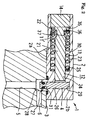
- Fig. 2 is a state in which a safety valve (1) is activated in response to an occurrence of abnormality.
- the safety valve (1) of the present invention includes: a cylindrical housing (2) provided with a fusible alloy (fusible material) (11), a movable body (12) configured to move in association with fusion of the fusible alloy (11), and a compression coil spring (13) configured to urge the movable body (12) toward the fusible alloy (11); a main body (3) fixed to a right end portion of the housing (2) and extending downward; a movable plug body (4) arranged in a movable plug body arrangement passage (5) in the main body (3) so that an upper end portion thereof projects inward of the housing (2) and moving in association with the movement of the movable body (12), and a relief passage (6) communicating with the movable plug body arrangement passage (5) and configured to be opened by the movement of the movable plug body (4).
- a fusible alloy fuusible material
- a movable body (12) configured to move in association with fusion of the fusible alloy (11)
- a compression coil spring (13) configured to urge the movable
- the safety valve (1) is used with the main body (3) thereof mounted on the container and is activated at the time of abnormality and, the abnormality corresponds, for example, to a case where a fire occurs and the temperature rises and, in this case, the fusible alloy (11) fuses at a predetermined temperature and, accordingly, the movable body (12) urged leftward by the compression coil spring (13) moves leftward to allow the movable plug body (4) to move, and accordingly, the movable plug body (4) is moved upward by the internal container pressure, whereby gas in the container is discharged through the movable plug body arrangement passage (5) and the relief passage (6) of the main body (3).
- a shape of the main body (3) is determined in accordance with a mounting form of the container and, only a principal portion is illustrated in Fig. 1 and Fig. 2 .
- the right end portion of the housing (2) is closed by a bottom wall (2b).
- a cap (14) is fitted and fixed to a left end portion of the housing (2).
- the movable body (12) includes a shaft portion (21) extending in leftward and rightward, and a flange portion (22) provided at a left end of the shaft portion (21).
- the fusible alloy (11) has a disc shape, and is arranged between a right surface of the cap (14) and a left surface of the flange portion (22) of the movable body (12).
- a large diameter cylindrical surface (23) having a diameter corresponding to an outer diameter of the flange portion (22) of the movable body (12) is formed in the interior of the housing (2) so as to extend rightward from the left end, and a small diameter cylindrical surface (24) having a diameter corresponding to the outer diameter of the shaft portion (21) of the movable body (12) is provided so as to continue from the right end of the large diameter cylindrical surface (23).
- a normally movable plug body positioning passage (26) extending downward is provided at the right end portion of the housing (2) so as to penetrate through a peripheral wall (2a) .
- a cylindrical projecting portion (27) extending downward from the peripheral wall (2a) is provided at an opening edge portion of the normally movable plug body positioning passage (26) of the peripheral wall (2a).
- the cylindrical projecting portion (27) is fitted to an upper portion of an annular fitting depression (28) provided on an upper surface of the main body (3).
- An in-operation movable plug body positioning depression (29) is provided so as to oppose the movable plug body positioning passage (26) via the small diameter cylindrical surface (24) provided on an upper surface of an inner periphery of a right end portion of the peripheral wall (2a) of the housing (2).
- the compression coil spring (13) is fitted into the large diameter cylindrical surface (23), is received at a left end by the right surface of the flange portion (22) of the movable body (12) and is received at a right end by a shouldered surface (25) at a boundary between the large diameter cylindrical surface (23) and the small diameter cylindrical surface (24).
- a portion between the large diameter cylindrical surface (23) and the shaft portion (21) of the movable body (12) corresponds to a compression coil spring arrangement space (30).
- the movable plug body (4) is fitted into the movable plug body arrangement passage (5) and the normally movable plug body positioning passage (26) so as to be movable and a seal ring (31) is fitted to an outer periphery thereof.
- the movable plug body (4) is brought into contact with a right end portion of the shaft portion (21) of the movable body (12), whereby the upward movement of the movable plug body (4) is prevented.
- the seal ring (31) provided on the movable plug body (4) is in tight contact with an inner peripheral surface of the movable plug body arrangement passage (5), whereby leakage of gas from the movable plug body arrangement passage (5) in the normal state is prevented.
- the movable plug body (4) is moved upward by the internal container pressure.
- the relief passage (6) is formed so as to continue from a lower portion of the fitting depression (28) on the upper surface of the main body (3) and extend in a direction orthogonal to the movable plug body arrangement passage (5). Therefore, when the lower end of the movable plug body (4) moves into the interior of the lower portion of the fitting depression (28), gas in the interior of the container is released via the relief passage (6).
- Four of the through holes (35) are provided at every 90° in the circumferential direction.
- the diameter of the through hole (35) is on the order of 1 to 2 mm, for example, ⁇ 1.5 mm.
- the flange portion (22) receives the compression coil spring (13), and the compression coil spring arrangement space (30) is provided on the right side of the flange portion (22), so that the through holes (35) communicate with the compression coil spring arrangement space (30).
- Counter borings (36) are formed at edge portions of the through holes (35) opening into the compression coil spring arrangement space (30).
- the shaft portion (21) of the movable body (12) is provided with an annular groove (37) communicating with the through holes (35) at the end portion on the flange portion side.
- the fusible alloy (11) When the temperatures of the safety valve (1) and the container become high, the fusible alloy (11) is fused at a predetermined temperature and is discharged into the compression coil spring arrangement space (30) through the through holes (35). At this time, the fused fusible alloy (11) spreads to a portion of the counter borings (36) of the through holes (35) as indicated by a numeral (11') in Fig. 2 , and flows into the annular groove (37). Accordingly, a flow of the fused fusible alloy (11') is not hindered by the compression coil spring (13), and is discharged reliably into the compression coil spring arrangement space (30).
- passages for discharging the fusible alloy (11) are formed without providing the housing (2) with the through hole opening toward the outside.
- this safety valve (1) since the through hole opening to the outside by penetrating through the peripheral wall (2a) of the housing (2) is not provided, entry of water and dust is prevented even in the case of being used under the environment which is susceptible to entry of water and dust, and hence clogging of the through hole (44) with the pin formed of a fusible alloy, which has been required in the related art, is no longer necessary, and hence the cost reduction may be achieved.
- the safety valve (1) of this embodiment described above was immersed in glycerin heated to 130°C and time required for activation was measured.
- the time required for activation of this invented article has no different from that of the related art illustrated in Fig. 3 . Since a resilient force (approximately 30 kg) of the compression coil spring (13) is applied to the movable body (12), when the fusible alloy (11) enters the through holes (35) of the movable body (12) by creeping, there arises a probability of erroneous operation. However, it was confirmed that there was no such erroneous operation.
Abstract
Description
- The present invention relates to a safety valve and, more specifically, to a safety valve configured to release gas in a container when being mounted on the container and increasing in temperature in order to prevent an internal container pressure from rising excessing at the time of occurrence of fire or the like.
- Known examples of such a safety valve include a safety valve provided with a fusible material configured to fuse at the time of high temperature and configured to release gas in a container by a movement of a movable plug body in association with fusion of the fusible material (PTL 1).
- An example of a safety valve of the related art is illustrated in
Fig. 3 . - This safety valve (41) of the related art includes: a cylindrical housing (42) provided with a fusible alloy (fusible material) (11), a movable body (43) configured to move in association with fusion of the fusible alloy (11) and a compression coil spring (13) configured to urge the movable body (43) toward the fusible alloy (11) ; a main body (3) fixed to a right end portion of the housing (42) and extending downward; a movable plug body (4) arranged in a movable plug body arrangement passage (5) in the main body (3) so that an upper end portion thereof projects inward of the housing (42) and configured to move in association of a movement of the movable body(43) ; and a relief passage (6) communicating with the movable plug body arrangement passage (5) and configured to be opened by the movement of the movable plug body (4).
- The safety valve (41) is used with the main body (3) thereof mounted on a container and, for example, a fire occurs and the temperature rises, the fusible alloy (11) fuses at a predetermined temperature and, accordingly, the movable body (43) urged leftward by the compression coil spring (13) moves leftward, and accordingly, the movable plug body (4) is allowed to move and is moved upward by an internal container pressure, whereby gas in the container is discharged through the movable plug body arrangement passage (5) and the relief passage (6) of the main body (3).
- With the safety valve (41) of the related art, a discharge port (44) of the fused fusible alloy (11) is provided so as to penetrate through a peripheral wall (42a) of the housing (42), and the fused fusible alloy (11) passes through the discharge port (44) and discharged to the outside of the housing (42).
PTL 1:JP-A-2008-202736 - The safety valve (41) of the related art has a probability of entry of water or dust into the safety valve (41) from the outside through the discharge port (through hole) (44) provided on the housing (42) and, in this case, an operation failure of the safety valve (41) may be caused. Therefore, the discharge port (44) is clogged with a pin formed of a fusible alloy. In this case, however, an increase in cost is caused.
- It is an object of the present invention to provide a safety valve mounted on the container and configured to release gas in a container in the case where the temperature rises, in which safety is secured and a cost reduction is achieved.
- The safety valve of the present invention is a safety valve including: a fusible material, a cylindrical housing provided with a movable body configured to move in association with fusion of the fusible material and a compression coil spring configured to urge the movable body toward the fusible material; a main body fixed to the housing; a movable plug body in the main body arranged in a movable plug body arrangement passage and configured to move in association with the movement of the movable body; a relief passage communicating with the movable plug body arrangement passage and configured to be opened by the movement of the movable plug body, characterized in that the movable body includes a shaft portion to which the compression coil spring is fitted, and a flange portion coming into contact with the fusible material by being urged by the compression coil spring, and the flange portion of the movable body is provided with through holes configured to discharge the fused fusible material into a compression coil spring arrangement space.
- The through holes may be four through holes each having a diameter of 1.5 mm, for example, and being provided equidistantly in a circumferential direction. However, the invention is not limited thereto, and the diameter and the number of the through holes may be set to suitable values.
- According to the safety valve of the present invention, in the case where a temperature in the periphery of the container to which the safety valve is mounted exceeds a fusing temperature of the fusible material, the fusible material is fused and, accordingly, the movable body moves to allow the movement of the movable plug body and the movable plug body moves by an internal container pressure, so that gas in the container is released through the movable plug body arrangement passage and the relief passage of the main body, whereby the container is prevented from bursting.
- The fused fusible material passes through the through holes provided on the flange portion of the movable body, and is discharged into the compression coil spring arrangement space. In other words, by using the compression coil spring arrangement space as a destination of discharge of the fused fusible material, a passage of the fused fusible material is formed in the interior of the safety valve. Accordingly, the discharge port provided in the related art so as to penetrate through a peripheral wall of the housing is no longer necessary, and hence entry of water and dust from the discharge port is avoided and hence the cause of the operation failure of the safety valve is eliminated. Therefore, clogging the discharging port with a pin formed of the fusible alloy is not necessary as well, so that the cost reduction is achieved.
- Preferably, counter borings are formed at edge portions of the through holes opening into the compression coil spring arrangement space. In other words, it is preferable to increase the size of exits of the passages of the fused fusible material and, in this configuration, the fused fusible material is reliably discharged.
- Further preferably, the shaft portion of the movable body is provided with an annular groove communicating with the through holes at end on the flange portion side. In this configuration, a space portion of the compression coil spring arrangement space, which is the destination of discharge of the fused fusible material, is increased in size, so that the fused fusible material can be discharged further reliably.
- According to the safety valve of the present invention, since the through hole penetrating through the peripheral wall of the housing may be eliminated, entry of water or dust is prevented even during the use under an environment susceptible to entry of water and dust. Therefore, clogging the discharging port with the pin formed of the fusible alloy, which has been necessary in the related art, is no longer necessary, so that the cost reduction is achieved.
-
- [
Fig. 1] Fig. 1 is a cross-sectional view of a safety valve according to an embodiment of the present invention, illustrating a normal state (closed state). - [
Fig. 2] Fig. 2 illustrates an operating state of the safety valve inFig. 1 . - [
Fig. 3] Fig. 3 is a cross-sectional view of a safety valve according to an embodiment of the related art, illustrating a normal state (closed state). - (1) : safety valve, (2) : housing, (3) : main body, (4) : movable plug body, (5): movable plug body arrangement passage, (6): relief passage, (11): fusible alloy (fusible material), (12): movable body, (13): compression coil spring, (21): shaft portion, (22) : flange portion, (30) : compression coil spring arrangement space, (35): through hole, (36): counter boring, (37): annular groove
- Embodiments of the invention will be described below with reference to the drawings. In the following description, up, down, left and right indicate up, down, left and right in figures. The expressions up and down are determined on the basis of the case where the safety valve is mounted on an upper surface of a container. However, the expressions up and down are for convenience only, and the safety valve may be mounted upside down or transversely from the reference state.
-
Fig. 1 andFig. 2 illustrate an embodiment of a safety valve of the present invention.Fig. 1 illustrates a normal state in which the environmental temperature of the safety vale is not higher than a predetermined value, that is, in a state in which the passages are closed.Fig. 2 is a state in which a safety valve (1) is activated in response to an occurrence of abnormality. - The safety valve (1) of the present invention includes: a cylindrical housing (2) provided with a fusible alloy (fusible material) (11), a movable body (12) configured to move in association with fusion of the fusible alloy (11), and a compression coil spring (13) configured to urge the movable body (12) toward the fusible alloy (11); a main body (3) fixed to a right end portion of the housing (2) and extending downward; a movable plug body (4) arranged in a movable plug body arrangement passage (5) in the main body (3) so that an upper end portion thereof projects inward of the housing (2) and moving in association with the movement of the movable body (12), and a relief passage (6) communicating with the movable plug body arrangement passage (5) and configured to be opened by the movement of the movable plug body (4).
- The safety valve (1) is used with the main body (3) thereof mounted on the container and is activated at the time of abnormality and, the abnormality corresponds, for example, to a case where a fire occurs and the temperature rises and, in this case, the fusible alloy (11) fuses at a predetermined temperature and, accordingly, the movable body (12) urged leftward by the compression coil spring (13) moves leftward to allow the movable plug body (4) to move, and accordingly, the movable plug body (4) is moved upward by the internal container pressure, whereby gas in the container is discharged through the movable plug body arrangement passage (5) and the relief passage (6) of the main body (3).
- A shape of the main body (3) is determined in accordance with a mounting form of the container and, only a principal portion is illustrated in
Fig. 1 andFig. 2 . - The right end portion of the housing (2) is closed by a bottom wall (2b). A cap (14) is fitted and fixed to a left end portion of the housing (2).
- The movable body (12) includes a shaft portion (21) extending in leftward and rightward, and a flange portion (22) provided at a left end of the shaft portion (21).
- The fusible alloy (11) has a disc shape, and is arranged between a right surface of the cap (14) and a left surface of the flange portion (22) of the movable body (12).
- A large diameter cylindrical surface (23) having a diameter corresponding to an outer diameter of the flange portion (22) of the movable body (12) is formed in the interior of the housing (2) so as to extend rightward from the left end, and a small diameter cylindrical surface (24) having a diameter corresponding to the outer diameter of the shaft portion (21) of the movable body (12) is provided so as to continue from the right end of the large diameter cylindrical surface (23).
- A normally movable plug body positioning passage (26) extending downward is provided at the right end portion of the housing (2) so as to penetrate through a peripheral wall (2a) . A cylindrical projecting portion (27) extending downward from the peripheral wall (2a) is provided at an opening edge portion of the normally movable plug body positioning passage (26) of the peripheral wall (2a). The cylindrical projecting portion (27) is fitted to an upper portion of an annular fitting depression (28) provided on an upper surface of the main body (3). An in-operation movable plug body positioning depression (29) is provided so as to oppose the movable plug body positioning passage (26) via the small diameter cylindrical surface (24) provided on an upper surface of an inner periphery of a right end portion of the peripheral wall (2a) of the housing (2).
- The compression coil spring (13) is fitted into the large diameter cylindrical surface (23), is received at a left end by the right surface of the flange portion (22) of the movable body (12) and is received at a right end by a shouldered surface (25) at a boundary between the large diameter cylindrical surface (23) and the small diameter cylindrical surface (24). A portion between the large diameter cylindrical surface (23) and the shaft portion (21) of the movable body (12) corresponds to a compression coil spring arrangement space (30).
- The movable plug body (4) is fitted into the movable plug body arrangement passage (5) and the normally movable plug body positioning passage (26) so as to be movable and a seal ring (31) is fitted to an outer periphery thereof. The movable plug body (4) is brought into contact with a right end portion of the shaft portion (21) of the movable body (12), whereby the upward movement of the movable plug body (4) is prevented. The seal ring (31) provided on the movable plug body (4) is in tight contact with an inner peripheral surface of the movable plug body arrangement passage (5), whereby leakage of gas from the movable plug body arrangement passage (5) in the normal state is prevented.
- In the case where the movable body (12) moves leftward and an upward movement of the movable plug body (4) is enabled, the movable plug body (4) is moved upward by the internal container pressure.
- The relief passage (6) is formed so as to continue from a lower portion of the fitting depression (28) on the upper surface of the main body (3) and extend in a direction orthogonal to the movable plug body arrangement passage (5). Therefore, when the lower end of the movable plug body (4) moves into the interior of the lower portion of the fitting depression (28), gas in the interior of the container is released via the relief passage (6).
- In the safety valve (1) of this embodiment, a discharge port (through hole) (44), which is provided in a housing (42), is eliminated in comparison with the safety valve of the related art illustrated in
Fig. 3 , and a plurality of through holes (35), which serve as discharge ports, are formed in the flange portion (22) of the movable body (12). Four of the through holes (35) are provided at every 90° in the circumferential direction. The diameter of the through hole (35) is on the order of 1 to 2 mm, for example, ϕ 1.5 mm. - The flange portion (22) receives the compression coil spring (13), and the compression coil spring arrangement space (30) is provided on the right side of the flange portion (22), so that the through holes (35) communicate with the compression coil spring arrangement space (30).
- Counter borings (36) are formed at edge portions of the through holes (35) opening into the compression coil spring arrangement space (30). The shaft portion (21) of the movable body (12) is provided with an annular groove (37) communicating with the through holes (35) at the end portion on the flange portion side.
- When the temperatures of the safety valve (1) and the container become high, the fusible alloy (11) is fused at a predetermined temperature and is discharged into the compression coil spring arrangement space (30) through the through holes (35). At this time, the fused fusible alloy (11) spreads to a portion of the counter borings (36) of the through holes (35) as indicated by a numeral (11') in
Fig. 2 , and flows into the annular groove (37). Accordingly, a flow of the fused fusible alloy (11') is not hindered by the compression coil spring (13), and is discharged reliably into the compression coil spring arrangement space (30). - In this manner, according to the safety valve (1) of the embodiment described above, passages (passages composed of the through holes (35), the counter borings (36), and the annular groove (37)) for discharging the fusible alloy (11) are formed without providing the housing (2) with the through hole opening toward the outside. With this safety valve (1), since the through hole opening to the outside by penetrating through the peripheral wall (2a) of the housing (2) is not provided, entry of water and dust is prevented even in the case of being used under the environment which is susceptible to entry of water and dust, and hence clogging of the through hole (44) with the pin formed of a fusible alloy, which has been required in the related art, is no longer necessary, and hence the cost reduction may be achieved.
- The safety valve (1) of this embodiment described above was immersed in glycerin heated to 130°C and time required for activation was measured. However, the time required for activation of this invented article has no different from that of the related art illustrated in
Fig. 3 . Since a resilient force (approximately 30 kg) of the compression coil spring (13) is applied to the movable body (12), when the fusible alloy (11) enters the through holes (35) of the movable body (12) by creeping, there arises a probability of erroneous operation. However, it was confirmed that there was no such erroneous operation. - It is an object of the present invention to provide a safety valve mounted on the container and configured to release gas in a container in the case where rising in temperature, in which the safety is secured and a cost is lowered, thereby contributing to an improvement of the safety of the container.
Claims (3)
- A safety valve comprising:a cylindrical housing provided with a fusible material, a movable body configured to move in association with fusion of the fusible material and a compression coil spring configured to urge the movable body toward the fusible material; a main body fixed to the housing; a movable plug body arranged in a movable plug body arrangement passage in the main body and configured to move in association with the movement of the movable body; a relief passage communicating with the movable plug body arrangement passage and configured to be opened by the movement of the movable plug body, whereinthe movable body includes a shaft portion to which the compression coil spring is fitted, and a flange portion coming into contact with the fusible material by being urged by the compression coil spring, and the flange portion of the movable body is provided with through holes configured to discharge the fused fusible material into a compression coil spring arrangement space.
- The safety valve according to Claim 1, wherein counter borings are formed at edge portions of the through holes opening into the compression coil spring arrangement space.
- The safety valve according to Claim 1 or 2, wherein the shaft portion of the movable body is provided with an annular groove communicating with the through holes at an end portion on the flange portion side.
Applications Claiming Priority (2)
| Application Number | Priority Date | Filing Date | Title |
|---|---|---|---|
| JP2013214480A JP5818854B2 (en) | 2013-10-15 | 2013-10-15 | safety valve |
| PCT/JP2014/077398 WO2015056696A1 (en) | 2013-10-15 | 2014-10-15 | Safety valve |
Publications (3)
| Publication Number | Publication Date |
|---|---|
| EP2949977A1 true EP2949977A1 (en) | 2015-12-02 |
| EP2949977A4 EP2949977A4 (en) | 2016-10-05 |
| EP2949977B1 EP2949977B1 (en) | 2018-01-10 |
Family
ID=52828139
Family Applications (1)
| Application Number | Title | Priority Date | Filing Date |
|---|---|---|---|
| EP14854659.1A Active EP2949977B1 (en) | 2013-10-15 | 2014-10-15 | Safety valve |
Country Status (5)
| Country | Link |
|---|---|
| US (1) | US9945489B2 (en) |
| EP (1) | EP2949977B1 (en) |
| JP (1) | JP5818854B2 (en) |
| CN (1) | CN105121927B (en) |
| WO (1) | WO2015056696A1 (en) |
Cited By (1)
| Publication number | Priority date | Publication date | Assignee | Title |
|---|---|---|---|---|
| DE102016106328A1 (en) * | 2016-04-06 | 2017-10-12 | Mesa Parts GmbH | Device for the temperature-dependent reduction of the pressure of a medium stored in a pressure tank |
Families Citing this family (7)
| Publication number | Priority date | Publication date | Assignee | Title |
|---|---|---|---|---|
| JP6387273B2 (en) * | 2014-09-05 | 2018-09-05 | 株式会社フジキン | safety valve |
| CN105972362B (en) * | 2016-07-13 | 2019-04-02 | 广东金尚智能电气有限公司 | Safety quick joint and connector parent, pin end for fuel gas conduit |
| KR20200132413A (en) * | 2019-05-17 | 2020-11-25 | 현대자동차주식회사 | Thermal-activated pressure relief device for fuel cell vehicle |
| CN112797315A (en) * | 2021-03-09 | 2021-05-14 | 广东欧佩亚氢能源科技有限公司 | Safety release valve for high-pressure hydrogen cylinder |
| KR102629435B1 (en) * | 2021-08-18 | 2024-01-25 | 태광후지킨 주식회사 | thermally-activated pressure relief safty device |
| CN113790393A (en) * | 2021-09-10 | 2021-12-14 | 张家港富瑞阀门有限公司 | Relief device, high-pressure hydrogen integrated cylinder valve with relief device and relief method |
| WO2023191573A1 (en) * | 2022-03-31 | 2023-10-05 | 남양넥스모 주식회사 | Temperature sensing reaction type safety valve for pressure container |
Family Cites Families (25)
| Publication number | Priority date | Publication date | Assignee | Title |
|---|---|---|---|---|
| US2181523A (en) * | 1937-11-29 | 1939-11-28 | Herbert H Shiels | Shut-off valve |
| US3227170A (en) * | 1963-05-20 | 1966-01-04 | Louis J Sigl | Fusible safety valve mounting |
| JPS485293Y1 (en) * | 1966-08-06 | 1973-02-10 | ||
| US3727636A (en) * | 1971-01-25 | 1973-04-17 | Parker Hannifin Corp | Flow control valve for fuel injection nozzle |
| US3705691A (en) * | 1971-09-08 | 1972-12-12 | Factory Mutual Res Corp | Discharge head utilizing a pressure-responsive detent mechanism |
| DE2919484C2 (en) * | 1979-05-15 | 1984-04-26 | Luco-Technic Gmbh Verfahrenstechnische Anlagen, 6474 Ortenberg | Device for wall cleaning using pressurized gas or steam |
| US4503675A (en) * | 1982-02-26 | 1985-03-12 | Xomox Corporation | Fail-safe actuator with fusible link |
| DE3700473C1 (en) * | 1987-01-09 | 1988-09-01 | Burger Armaturen Gmbh | Wall lead-through |
| US5109881A (en) * | 1990-08-23 | 1992-05-05 | Cooper Industries, Inc. | Temperature sensitive control valve |
| DE9017534U1 (en) | 1990-12-28 | 1991-03-21 | Streif, Hans, Magliaso, Lugano, Ch | |
| US5275194A (en) * | 1992-11-30 | 1994-01-04 | Donald E. Oates | Fire control valve with replaceable locking pin assembly |
| US5562118A (en) | 1995-07-21 | 1996-10-08 | Pgi International, Ltd. | Emergency shutoff valve with a fusible link and method |
| US6269830B1 (en) * | 1998-09-28 | 2001-08-07 | Gas Research Institute | Extended area thermal activation device |
| US6367499B2 (en) * | 2000-03-02 | 2002-04-09 | Hamai Industries Limited | Safety valve |
| JP3820483B2 (en) * | 2003-03-03 | 2006-09-13 | 株式会社フジキン | safety valve |
| JP4466193B2 (en) | 2003-10-21 | 2010-05-26 | トヨタ自動車株式会社 | Melting plug |
| CA2585582C (en) * | 2004-11-11 | 2010-08-10 | Kabushiki Kaisha Kawasaki Precision Machinery | Safety valve device |
| CN2867018Y (en) * | 2005-12-15 | 2007-02-07 | 李国才 | Automatic controlling valve by temperature sensing |
| JP2008202736A (en) | 2007-02-22 | 2008-09-04 | Fujikin Inc | Safety valve |
| JP2009058088A (en) | 2007-09-03 | 2009-03-19 | Neriki:Kk | Pressure relief valve |
| JP5255901B2 (en) * | 2008-05-16 | 2013-08-07 | 川崎重工業株式会社 | Safety valve device |
| US8141574B2 (en) * | 2008-05-29 | 2012-03-27 | Pacific Consolidated Industries, Llc | Thermally activated pressure relief |
| US8844554B2 (en) * | 2008-07-17 | 2014-09-30 | Kabushiki Kaisha Toshiba | Valve mechanism opened in response to extremely high temperature |
| JP5386249B2 (en) * | 2009-07-03 | 2014-01-15 | トヨタ自動車株式会社 | Valve device for high-pressure tank for vehicles |
| JP5775688B2 (en) | 2010-12-20 | 2015-09-09 | 株式会社フジキン | Soluble valve for safety valve |
-
2013
- 2013-10-15 JP JP2013214480A patent/JP5818854B2/en active Active
-
2014
- 2014-10-15 WO PCT/JP2014/077398 patent/WO2015056696A1/en active Application Filing
- 2014-10-15 EP EP14854659.1A patent/EP2949977B1/en active Active
- 2014-10-15 US US14/917,156 patent/US9945489B2/en active Active
- 2014-10-15 CN CN201480019649.6A patent/CN105121927B/en active Active
Cited By (2)
| Publication number | Priority date | Publication date | Assignee | Title |
|---|---|---|---|---|
| DE102016106328A1 (en) * | 2016-04-06 | 2017-10-12 | Mesa Parts GmbH | Device for the temperature-dependent reduction of the pressure of a medium stored in a pressure tank |
| DE102016106328B4 (en) | 2016-04-06 | 2021-12-16 | Mesa Parts GmbH | Device for the temperature-dependent reduction of the pressure of a medium stored in a pressure tank |
Also Published As
| Publication number | Publication date |
|---|---|
| CN105121927B (en) | 2017-09-01 |
| EP2949977A4 (en) | 2016-10-05 |
| CN105121927A (en) | 2015-12-02 |
| JP2015078709A (en) | 2015-04-23 |
| US9945489B2 (en) | 2018-04-17 |
| JP5818854B2 (en) | 2015-11-18 |
| EP2949977B1 (en) | 2018-01-10 |
| WO2015056696A1 (en) | 2015-04-23 |
| US20160195193A1 (en) | 2016-07-07 |
Similar Documents
| Publication | Publication Date | Title |
|---|---|---|
| EP2949977B1 (en) | Safety valve | |
| CN108028338B (en) | Pressure balancing device | |
| US20210320376A1 (en) | Degassing Unit, Electronics Housing, in Particular Battery Housing, and Motor Vehicle | |
| US9562619B2 (en) | Safety valve | |
| JP2008202736A (en) | Safety valve | |
| US20150240839A1 (en) | Accumulator | |
| JP6926201B2 (en) | Fluid discharge device | |
| US10209153B2 (en) | Pressure indicating device | |
| JP4427371B2 (en) | safety valve | |
| JP4900714B2 (en) | Fusible stopper | |
| JP2009058088A (en) | Pressure relief valve | |
| JP6387273B2 (en) | safety valve | |
| JP7054515B2 (en) | Fusible plug type safety valve | |
| JP6379193B2 (en) | Burst device for high voltage devices | |
| JP6388439B2 (en) | Pressure switch for oil pressure detection | |
| JP2008095731A (en) | Relief valve | |
| EP3578829B1 (en) | Accumulator | |
| EP4015884A1 (en) | Venting valve | |
| WO2022030340A1 (en) | Safety valve and discharge direction regulation member | |
| RU2575186C1 (en) | Safety membrane device | |
| JP2005147385A (en) | Fusible plug | |
| KR20230126122A (en) | Pressure relief device | |
| JP6575844B2 (en) | safety valve | |
| JP5679392B1 (en) | safety valve | |
| JP2004270809A (en) | Safety valve |
Legal Events
| Date | Code | Title | Description |
|---|---|---|---|
| PUAI | Public reference made under article 153(3) epc to a published international application that has entered the european phase |
Free format text: ORIGINAL CODE: 0009012 |
|
| 17P | Request for examination filed |
Effective date: 20150807 |
|
| AK | Designated contracting states |
Kind code of ref document: A1 Designated state(s): AL AT BE BG CH CY CZ DE DK EE ES FI FR GB GR HR HU IE IS IT LI LT LU LV MC MK MT NL NO PL PT RO RS SE SI SK SM TR |
|
| AX | Request for extension of the european patent |
Extension state: BA ME |
|
| A4 | Supplementary search report drawn up and despatched |
Effective date: 20160902 |
|
| RIC1 | Information provided on ipc code assigned before grant |
Ipc: F16K 17/38 20060101AFI20160829BHEP |
|
| DAX | Request for extension of the european patent (deleted) | ||
| GRAP | Despatch of communication of intention to grant a patent |
Free format text: ORIGINAL CODE: EPIDOSNIGR1 |
|
| INTG | Intention to grant announced |
Effective date: 20170828 |
|
| GRAS | Grant fee paid |
Free format text: ORIGINAL CODE: EPIDOSNIGR3 |
|
| GRAA | (expected) grant |
Free format text: ORIGINAL CODE: 0009210 |
|
| AK | Designated contracting states |
Kind code of ref document: B1 Designated state(s): AL AT BE BG CH CY CZ DE DK EE ES FI FR GB GR HR HU IE IS IT LI LT LU LV MC MK MT NL NO PL PT RO RS SE SI SK SM TR |
|
| REG | Reference to a national code |
Ref country code: CH Ref legal event code: EP Ref country code: AT Ref legal event code: REF Ref document number: 962778 Country of ref document: AT Kind code of ref document: T Effective date: 20180115 |
|
| REG | Reference to a national code |
Ref country code: IE Ref legal event code: FG4D |
|
| REG | Reference to a national code |
Ref country code: DE Ref legal event code: R096 Ref document number: 602014019767 Country of ref document: DE |
|
| REG | Reference to a national code |
Ref country code: NL Ref legal event code: MP Effective date: 20180110 |
|
| REG | Reference to a national code |
Ref country code: AT Ref legal event code: MK05 Ref document number: 962778 Country of ref document: AT Kind code of ref document: T Effective date: 20180110 |
|
| PG25 | Lapsed in a contracting state [announced via postgrant information from national office to epo] |
Ref country code: NL Free format text: LAPSE BECAUSE OF FAILURE TO SUBMIT A TRANSLATION OF THE DESCRIPTION OR TO PAY THE FEE WITHIN THE PRESCRIBED TIME-LIMIT Effective date: 20180110 |
|
| PG25 | Lapsed in a contracting state [announced via postgrant information from national office to epo] |
Ref country code: HR Free format text: LAPSE BECAUSE OF FAILURE TO SUBMIT A TRANSLATION OF THE DESCRIPTION OR TO PAY THE FEE WITHIN THE PRESCRIBED TIME-LIMIT Effective date: 20180110 Ref country code: LT Free format text: LAPSE BECAUSE OF FAILURE TO SUBMIT A TRANSLATION OF THE DESCRIPTION OR TO PAY THE FEE WITHIN THE PRESCRIBED TIME-LIMIT Effective date: 20180110 Ref country code: NO Free format text: LAPSE BECAUSE OF FAILURE TO SUBMIT A TRANSLATION OF THE DESCRIPTION OR TO PAY THE FEE WITHIN THE PRESCRIBED TIME-LIMIT Effective date: 20180410 Ref country code: CY Free format text: LAPSE BECAUSE OF FAILURE TO SUBMIT A TRANSLATION OF THE DESCRIPTION OR TO PAY THE FEE WITHIN THE PRESCRIBED TIME-LIMIT Effective date: 20180110 Ref country code: ES Free format text: LAPSE BECAUSE OF FAILURE TO SUBMIT A TRANSLATION OF THE DESCRIPTION OR TO PAY THE FEE WITHIN THE PRESCRIBED TIME-LIMIT Effective date: 20180110 Ref country code: FI Free format text: LAPSE BECAUSE OF FAILURE TO SUBMIT A TRANSLATION OF THE DESCRIPTION OR TO PAY THE FEE WITHIN THE PRESCRIBED TIME-LIMIT Effective date: 20180110 |
|
| PG25 | Lapsed in a contracting state [announced via postgrant information from national office to epo] |
Ref country code: AT Free format text: LAPSE BECAUSE OF FAILURE TO SUBMIT A TRANSLATION OF THE DESCRIPTION OR TO PAY THE FEE WITHIN THE PRESCRIBED TIME-LIMIT Effective date: 20180110 Ref country code: SE Free format text: LAPSE BECAUSE OF FAILURE TO SUBMIT A TRANSLATION OF THE DESCRIPTION OR TO PAY THE FEE WITHIN THE PRESCRIBED TIME-LIMIT Effective date: 20180110 Ref country code: LV Free format text: LAPSE BECAUSE OF FAILURE TO SUBMIT A TRANSLATION OF THE DESCRIPTION OR TO PAY THE FEE WITHIN THE PRESCRIBED TIME-LIMIT Effective date: 20180110 Ref country code: GR Free format text: LAPSE BECAUSE OF FAILURE TO SUBMIT A TRANSLATION OF THE DESCRIPTION OR TO PAY THE FEE WITHIN THE PRESCRIBED TIME-LIMIT Effective date: 20180411 Ref country code: PL Free format text: LAPSE BECAUSE OF FAILURE TO SUBMIT A TRANSLATION OF THE DESCRIPTION OR TO PAY THE FEE WITHIN THE PRESCRIBED TIME-LIMIT Effective date: 20180110 Ref country code: IS Free format text: LAPSE BECAUSE OF FAILURE TO SUBMIT A TRANSLATION OF THE DESCRIPTION OR TO PAY THE FEE WITHIN THE PRESCRIBED TIME-LIMIT Effective date: 20180510 Ref country code: BG Free format text: LAPSE BECAUSE OF FAILURE TO SUBMIT A TRANSLATION OF THE DESCRIPTION OR TO PAY THE FEE WITHIN THE PRESCRIBED TIME-LIMIT Effective date: 20180410 Ref country code: RS Free format text: LAPSE BECAUSE OF FAILURE TO SUBMIT A TRANSLATION OF THE DESCRIPTION OR TO PAY THE FEE WITHIN THE PRESCRIBED TIME-LIMIT Effective date: 20180110 |
|
| REG | Reference to a national code |
Ref country code: DE Ref legal event code: R097 Ref document number: 602014019767 Country of ref document: DE |
|
| PG25 | Lapsed in a contracting state [announced via postgrant information from national office to epo] |
Ref country code: AL Free format text: LAPSE BECAUSE OF FAILURE TO SUBMIT A TRANSLATION OF THE DESCRIPTION OR TO PAY THE FEE WITHIN THE PRESCRIBED TIME-LIMIT Effective date: 20180110 Ref country code: RO Free format text: LAPSE BECAUSE OF FAILURE TO SUBMIT A TRANSLATION OF THE DESCRIPTION OR TO PAY THE FEE WITHIN THE PRESCRIBED TIME-LIMIT Effective date: 20180110 Ref country code: IT Free format text: LAPSE BECAUSE OF FAILURE TO SUBMIT A TRANSLATION OF THE DESCRIPTION OR TO PAY THE FEE WITHIN THE PRESCRIBED TIME-LIMIT Effective date: 20180110 Ref country code: EE Free format text: LAPSE BECAUSE OF FAILURE TO SUBMIT A TRANSLATION OF THE DESCRIPTION OR TO PAY THE FEE WITHIN THE PRESCRIBED TIME-LIMIT Effective date: 20180110 |
|
| PLBE | No opposition filed within time limit |
Free format text: ORIGINAL CODE: 0009261 |
|
| STAA | Information on the status of an ep patent application or granted ep patent |
Free format text: STATUS: NO OPPOSITION FILED WITHIN TIME LIMIT |
|
| PG25 | Lapsed in a contracting state [announced via postgrant information from national office to epo] |
Ref country code: SM Free format text: LAPSE BECAUSE OF FAILURE TO SUBMIT A TRANSLATION OF THE DESCRIPTION OR TO PAY THE FEE WITHIN THE PRESCRIBED TIME-LIMIT Effective date: 20180110 Ref country code: CZ Free format text: LAPSE BECAUSE OF FAILURE TO SUBMIT A TRANSLATION OF THE DESCRIPTION OR TO PAY THE FEE WITHIN THE PRESCRIBED TIME-LIMIT Effective date: 20180110 Ref country code: DK Free format text: LAPSE BECAUSE OF FAILURE TO SUBMIT A TRANSLATION OF THE DESCRIPTION OR TO PAY THE FEE WITHIN THE PRESCRIBED TIME-LIMIT Effective date: 20180110 Ref country code: SK Free format text: LAPSE BECAUSE OF FAILURE TO SUBMIT A TRANSLATION OF THE DESCRIPTION OR TO PAY THE FEE WITHIN THE PRESCRIBED TIME-LIMIT Effective date: 20180110 |
|
| 26N | No opposition filed |
Effective date: 20181011 |
|
| PG25 | Lapsed in a contracting state [announced via postgrant information from national office to epo] |
Ref country code: SI Free format text: LAPSE BECAUSE OF FAILURE TO SUBMIT A TRANSLATION OF THE DESCRIPTION OR TO PAY THE FEE WITHIN THE PRESCRIBED TIME-LIMIT Effective date: 20180110 |
|
| REG | Reference to a national code |
Ref country code: DE Ref legal event code: R084 Ref document number: 602014019767 Country of ref document: DE |
|
| REG | Reference to a national code |
Ref country code: CH Ref legal event code: PL |
|
| GBPC | Gb: european patent ceased through non-payment of renewal fee |
Effective date: 20181015 |
|
| REG | Reference to a national code |
Ref country code: BE Ref legal event code: MM Effective date: 20181031 |
|
| PG25 | Lapsed in a contracting state [announced via postgrant information from national office to epo] |
Ref country code: LU Free format text: LAPSE BECAUSE OF NON-PAYMENT OF DUE FEES Effective date: 20181015 Ref country code: MC Free format text: LAPSE BECAUSE OF FAILURE TO SUBMIT A TRANSLATION OF THE DESCRIPTION OR TO PAY THE FEE WITHIN THE PRESCRIBED TIME-LIMIT Effective date: 20180110 |
|
| REG | Reference to a national code |
Ref country code: IE Ref legal event code: MM4A |
|
| PG25 | Lapsed in a contracting state [announced via postgrant information from national office to epo] |
Ref country code: LI Free format text: LAPSE BECAUSE OF NON-PAYMENT OF DUE FEES Effective date: 20181031 Ref country code: FR Free format text: LAPSE BECAUSE OF NON-PAYMENT OF DUE FEES Effective date: 20181031 Ref country code: CH Free format text: LAPSE BECAUSE OF NON-PAYMENT OF DUE FEES Effective date: 20181031 Ref country code: BE Free format text: LAPSE BECAUSE OF NON-PAYMENT OF DUE FEES Effective date: 20181031 |
|
| PG25 | Lapsed in a contracting state [announced via postgrant information from national office to epo] |
Ref country code: IE Free format text: LAPSE BECAUSE OF NON-PAYMENT OF DUE FEES Effective date: 20181015 Ref country code: GB Free format text: LAPSE BECAUSE OF NON-PAYMENT OF DUE FEES Effective date: 20181015 |
|
| PG25 | Lapsed in a contracting state [announced via postgrant information from national office to epo] |
Ref country code: MT Free format text: LAPSE BECAUSE OF NON-PAYMENT OF DUE FEES Effective date: 20181015 |
|
| PG25 | Lapsed in a contracting state [announced via postgrant information from national office to epo] |
Ref country code: TR Free format text: LAPSE BECAUSE OF FAILURE TO SUBMIT A TRANSLATION OF THE DESCRIPTION OR TO PAY THE FEE WITHIN THE PRESCRIBED TIME-LIMIT Effective date: 20180110 |
|
| PG25 | Lapsed in a contracting state [announced via postgrant information from national office to epo] |
Ref country code: PT Free format text: LAPSE BECAUSE OF FAILURE TO SUBMIT A TRANSLATION OF THE DESCRIPTION OR TO PAY THE FEE WITHIN THE PRESCRIBED TIME-LIMIT Effective date: 20180110 |
|
| PG25 | Lapsed in a contracting state [announced via postgrant information from national office to epo] |
Ref country code: MK Free format text: LAPSE BECAUSE OF NON-PAYMENT OF DUE FEES Effective date: 20180110 Ref country code: HU Free format text: LAPSE BECAUSE OF FAILURE TO SUBMIT A TRANSLATION OF THE DESCRIPTION OR TO PAY THE FEE WITHIN THE PRESCRIBED TIME-LIMIT; INVALID AB INITIO Effective date: 20141015 |
|
| P01 | Opt-out of the competence of the unified patent court (upc) registered |
Effective date: 20230512 |
|
| PGFP | Annual fee paid to national office [announced via postgrant information from national office to epo] |
Ref country code: DE Payment date: 20230830 Year of fee payment: 10 |