EP2949912B1 - System and method for controlling an electric aspirator of an air intake system for a work vehicle - Google Patents
System and method for controlling an electric aspirator of an air intake system for a work vehicle Download PDFInfo
- Publication number
- EP2949912B1 EP2949912B1 EP15169685.3A EP15169685A EP2949912B1 EP 2949912 B1 EP2949912 B1 EP 2949912B1 EP 15169685 A EP15169685 A EP 15169685A EP 2949912 B1 EP2949912 B1 EP 2949912B1
- Authority
- EP
- European Patent Office
- Prior art keywords
- air intake
- cleaner
- aspirator
- air
- particulates
- Prior art date
- Legal status (The legal status is an assumption and is not a legal conclusion. Google has not performed a legal analysis and makes no representation as to the accuracy of the status listed.)
- Active
Links
Images


Classifications
-
- F—MECHANICAL ENGINEERING; LIGHTING; HEATING; WEAPONS; BLASTING
- F02—COMBUSTION ENGINES; HOT-GAS OR COMBUSTION-PRODUCT ENGINE PLANTS
- F02M—SUPPLYING COMBUSTION ENGINES IN GENERAL WITH COMBUSTIBLE MIXTURES OR CONSTITUENTS THEREOF
- F02M35/00—Combustion-air cleaners, air intakes, intake silencers, or induction systems specially adapted for, or arranged on, internal-combustion engines
- F02M35/02—Air cleaners
- F02M35/08—Air cleaners with means for removing dust, particles or liquids from cleaners; with means for indicating clogging; with by-pass means; Regeneration of cleaners
- F02M35/086—Dust removal by flushing, blasting, pulsating or aspirating flow, washing or the like; Mechanical dust removal, e.g. by using scrapers
-
- B—PERFORMING OPERATIONS; TRANSPORTING
- B01—PHYSICAL OR CHEMICAL PROCESSES OR APPARATUS IN GENERAL
- B01D—SEPARATION
- B01D45/00—Separating dispersed particles from gases or vapours by gravity, inertia, or centrifugal forces
- B01D45/12—Separating dispersed particles from gases or vapours by gravity, inertia, or centrifugal forces by centrifugal forces
-
- B—PERFORMING OPERATIONS; TRANSPORTING
- B01—PHYSICAL OR CHEMICAL PROCESSES OR APPARATUS IN GENERAL
- B01D—SEPARATION
- B01D45/00—Separating dispersed particles from gases or vapours by gravity, inertia, or centrifugal forces
- B01D45/18—Cleaning-out devices
-
- B—PERFORMING OPERATIONS; TRANSPORTING
- B01—PHYSICAL OR CHEMICAL PROCESSES OR APPARATUS IN GENERAL
- B01D—SEPARATION
- B01D50/00—Combinations of methods or devices for separating particles from gases or vapours
- B01D50/20—Combinations of devices covered by groups B01D45/00 and B01D46/00
-
- F—MECHANICAL ENGINEERING; LIGHTING; HEATING; WEAPONS; BLASTING
- F02—COMBUSTION ENGINES; HOT-GAS OR COMBUSTION-PRODUCT ENGINE PLANTS
- F02M—SUPPLYING COMBUSTION ENGINES IN GENERAL WITH COMBUSTIBLE MIXTURES OR CONSTITUENTS THEREOF
- F02M35/00—Combustion-air cleaners, air intakes, intake silencers, or induction systems specially adapted for, or arranged on, internal-combustion engines
- F02M35/02—Air cleaners
- F02M35/022—Air cleaners acting by gravity, by centrifugal, or by other inertial forces, e.g. with moistened walls
- F02M35/0223—Air cleaners acting by gravity, by centrifugal, or by other inertial forces, e.g. with moistened walls by centrifugal forces, e.g. cyclones
-
- F—MECHANICAL ENGINEERING; LIGHTING; HEATING; WEAPONS; BLASTING
- F02—COMBUSTION ENGINES; HOT-GAS OR COMBUSTION-PRODUCT ENGINE PLANTS
- F02M—SUPPLYING COMBUSTION ENGINES IN GENERAL WITH COMBUSTIBLE MIXTURES OR CONSTITUENTS THEREOF
- F02M35/00—Combustion-air cleaners, air intakes, intake silencers, or induction systems specially adapted for, or arranged on, internal-combustion engines
- F02M35/02—Air cleaners
- F02M35/08—Air cleaners with means for removing dust, particles or liquids from cleaners; with means for indicating clogging; with by-pass means; Regeneration of cleaners
- F02M35/09—Clogging indicators ; Diagnosis or testing of air cleaners
-
- F—MECHANICAL ENGINEERING; LIGHTING; HEATING; WEAPONS; BLASTING
- F02—COMBUSTION ENGINES; HOT-GAS OR COMBUSTION-PRODUCT ENGINE PLANTS
- F02M—SUPPLYING COMBUSTION ENGINES IN GENERAL WITH COMBUSTIBLE MIXTURES OR CONSTITUENTS THEREOF
- F02M35/00—Combustion-air cleaners, air intakes, intake silencers, or induction systems specially adapted for, or arranged on, internal-combustion engines
- F02M35/10—Air intakes; Induction systems
- F02M35/104—Intake manifolds
Definitions
- the present subject matter relates generally to work vehicles and, more particularly, to a system and method for controlling an electric aspirator of an air intake system for a work vehicle.
- Work vehicles typically include internal combustion engines that require clean air for use within the combustion process. Since many work vehicles, such as tractors and other agricultural vehicles, operate in fields and other harvesting environments in which the ambient air contains large amounts of dust, plant material and other particulates, an air intake system having an effective filter assembly is required.
- conventional filter assemblies for work vehicles typically include a vortex or cyclone pre-cleaner configured to separate large particulates from the intake air and a porous air filter downstream of the pre-cleaner to provide the final stage of filtering prior to delivering the air into the engine.
- the large particulates separated from the intake air by the pre-cleaner must be removed from the filter assembly.
- such particulates are removed from the filter assembly via an outlet duct using a vacuum generated by the exhaust flow from the engine.
- the vacuum generated by the exhaust flow is often insufficient to meet the performance requirements of the filter assembly, thereby causing the air filter to plug within a short period of time.
- the present subject matter is directed to a system for controlling an air intake system for a work vehicle.
- the system may generally include a filter assembly having a pre-cleaner configured to separate particulates from air received by the filter assembly.
- the pre-cleaner may define a pre-cleaner outlet.
- the system may also include an electric aspirator in fluid communication with the pre-cleaner outlet.
- the electric aspirator may include a motor configured to rotate a fan so as to create a vacuum for scavenging the particulates separated from the air within the pre-cleaner.
- the system may include a controller communicatively coupled to the electric aspirator. The controller may be configured to vary a rotational speed of the motor based on changes in a load-based parameter of the work vehicle.
- the present subject matter is directed to a system for controlling an air intake system for a work vehicle.
- the system may generally include a filter assembly having a pre-cleaner configured to separate particulates from air received by the filter assembly.
- the pre-cleaner may define a pre-cleaner outlet.
- the system may also include an electric aspirator in fluid communication with the pre-cleaner outlet.
- the electric aspirator may include a motor configured to rotate a fan so as to create a vacuum for scavenging the particulates separated from the air within the pre-cleaner.
- the system may include a controller communicatively coupled to the electric aspirator.
- the controller may be configured to determine an air intake flow into an engine of the work vehicle and vary a rotational speed of the motor based on changes in the air intake flow. Specifically, the rotational speed of the motor may be varied such that a predetermined percentage of the air intake flow is scavenged from the pre-cleaner.
- the present subject matter is directed to a method for controlling an air intake system for a work vehicle.
- the method may generally include applying a vacuum via an electric aspirator to a pre-cleaner outlet of a pre-cleaner of the air intake system for scavenging particulates separated from air within the pre-cleaner, monitoring a load-based parameter of the work vehicle and varying a rotational speed of a motor of the electric aspirator based on changes in the load-based parameter.
- the present subject matter is directed to a system and method for controlling an air intake system of a work vehicle.
- the air intake system may include a filter assembly having a pre-cleaner configured to separate particulates from the air flowing into the system and an air filter disposed downstream of the pre-cleaner.
- the air intake system may include an electric aspirator configured to aspirate the pre-cleaner by creating a vacuum that sucks the particulates out of the pre-cleaner.
- the rotational speed at which a motor of the electric aspirator is rotated may be varied based on a load-based parameter of the work vehicle.
- the load-based parameter may correspond to an intake air flow of the engine of the work vehicle.
- FIG. 1 illustrates a side view of one embodiment of a work vehicle 10.
- the work vehicle 10 is configured as an agricultural tractor.
- the work vehicle 10 may be configured as any other suitable work vehicle known in the art, such as various other agricultural vehicles, earth-moving vehicles, road vehicles, loaders and/or the like.
- the work vehicle 10 includes a pair of front wheels 12, a pair or rear wheels 14 and a chassis 16 coupled to and supported by the wheels 12, 14.
- An operator's cab 18 may be supported by a portion of the chassis 16 and may house various control devices 20 (e.g., levers, pedals, control panels and/or the like) for permitting an operator to control the operation of the work vehicle 10.
- the work vehicle 10 may include an engine 22 and a transmission 24 mounted on the chassis 16.
- the transmission 24 may be operably coupled to the engine 22 and may provide variably adjusted gear ratios for transferring engine power to the wheels 14 via a differential 26.
- the engine 22, transmission 24, and differential 26 may collectively define a drive train 28 of the work vehicle 10.
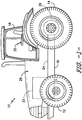
- the air intake system 30 may generally include a filter assembly 32 configured to receive dirty air from an intake duct 34 and clean/filter such air for subsequent delivery to the engine 22.
- the filter assembly 32 may include a pre-cleaner 36 and an air filter 38 disposed downstream of the pre-cleaner 36.
- the filter assembly 32 may include a pre-cleaner housing 40 configured to encase the pre-cleaner 36 and a filter housing 42 configured to encase the air filter 38.
- pre-cleaner housing 40 and the filter housing may 42 be formed integrally with one another (e.g., by forming both housings 40, 42 as a single continuous housing) or the pre-cleaner housing 40 and the filter housing 42 may comprise separate components configured to be separately coupled to one another
- the pre-cleaner 36 may be configured to remove portions of the dust, dirt, debris, plant matter and other particulates contained within the air flowing into the filter assembly 32 via the intake duct 34.
- the pre-cleaner 36 may include a plurality of tubes (e.g., turbo tubes), dirt separators, and/or any other suitable pre-cleaner elements 44 configured to separate particulates from the air via centripetal force.
- the pre-cleaner elements 44 may be configured to impart a vortex or spinning motion to the flow of air entering the filter assembly 32.
- pre-cleaner outlet 46 a scavenge or outlet port 46 defined in the pre-cleaner housing 40
- the air filter 38 may generally be configured to receive the cleaned air flowing from the pre-cleaner 36 and filter such air to provide a final stage of filtering prior to delivery of the air to the engine 22.
- the air filter 38 may generally include one or more filter elements 48 configured to catch or trap the remaining particulates contained within the cleaned air.
- the filter element(s) 48 may be made from a fibrous, porous or mesh material that allows air to pass therethrough while catching/trapping any particulates. The cleaned/filtered air may then be directed through a suitable conduit 50 to the engine 22, where the air may be mixed with fuel and combusted.
- the disclosed air intake system 30 may also include a conduit 52 having an upstream end 53 in fluid communication with the pre-cleaner outlet 46 and a downstream end 55 in fluid communication with an electric aspirator 54 configured to aspirate the pre-cleaner 36.
- the aspirator 54 may be configured to generate a vacuum that sucks the particulates flowing along the inner wall of the pre-cleaner housing 40 out the pre-cleaner outlet 46 and through the conduit 52. The particulates may then be expelled from the aspirator 54 back into the environment.
- the conduit 52 may generally be any suitable elongated member configured for the flow of air and/or fluid therethrough.
- the conduit 52 may comprise a tube, hose, pipe, duct and/or any other conduit-like member defining a passageway for the flow of air/fluid.
- FIG. 3 illustrates a cross-sectional view of the aspirator 54 shown in FIG. 2 , particularly illustrating a cross-sectional view in a widthwise direction of the aspirator 54.
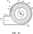
- FIG. 4 illustrates another cross-sectional view of the aspirator 54 shown in FIG. 2 , particularly illustrating a cross-sectional view taken about line 4-4 shown in FIG. 3 .
- the disclosed aspirator 54 may, in several embodiments, be configured as an electric blower and, thus, may generally include an electric motor 70 configured to rotationally drive a fan 72 such that a negative pressure or vacuum is generated within the aspirator 54 and the conduit 52 that is capable of aspirating the pre-cleaner 36.
- the fan 72 may be mounted to an output shaft 74 of the motor 70 such that rotation of the output shaft 74 rotationally drives the fan 72 about a rotational axis 76 of the motor 70.
- the motor 70 may be configured to rotate the fan 72 at a variable speed, for example, depending on n load-based parameter of the work vehicle 10.
- the fan 72 may generally have any suitable configuration that permits it to function as described herein.
- the fan may be configured as a blower or centrifugal fan (also referred to as a squirrel cage fan) and may include a plurality of blades 73 (e.g., straight radial blades, forward-curved blades or backwards-curved blades) mounted to a suitable base or hub 75.
- a blower or centrifugal fan also referred to as a squirrel cage fan
- blades 73 e.g., straight radial blades, forward-curved blades or backwards-curved blades
- the aspirator 54 may also include a housing 80 configured to encase and/or support the motor 70 and the fan 72.
- the housing 80 may be generally cylindrically shaped and may include a first endwall 81, a second endwall 82 and a circumferential sidewall 83 extending between the first and second endwalls 81, 82.
- the endwalls 81, 82 and the sidewall 83 may generally define an enclosed, cylindrical volume 84 (hereinafter referred to as the "fan compartment 84") within which the fan 72 may be rotationally disposed.
- the motor 70 may be coupled to the housing 80 (e.g., using suitable mechanical fasteners, such as bolts, screws, brackets and/or the like) in a manner that permits the motor 70 to rotationally drive the fan 72 within the fan compartment 84.
- suitable mechanical fasteners such as bolts, screws, brackets and/or the like
- an opening 85 may be defined in the first endwall 81 such that, when the motor 70 is coupled to the housing 80, the output shaft 74 may extend through the opening 85 in order to rotationally drive the fan 72.
- the aspirator 54 may include an aspirator inlet 86 and an aspirator outlet 87 defined by the housing 80.
- the aspirator inlet 86 may be configured to be in fluid communication with the conduit 52 such that particulates flowing through the conduit 52 may be directed into the fan compartment 84 via the aspirator inlet 86.
- the housing 80 may be configured such that the aspirator inlet 86 is defined by the second endwall 82 of the housing 80.
- aspirator inlet 86 may, for example, be positioned along the second endwall 82 such that an inlet centerline 88 of the aspirator inlet 86 is generally aligned with and/or extends parallel to the rotational axis 76 of the motor/fan 70, 72. As such, the flow of particulates through the aspirator inlet 86 and into the fan compartment 84 may be directed along a flow path that is generally parallel to the rotational axis 76.
- the aspirator inlet 86 may be defined at any other suitable location on the housing 80 and the inlet centerline 88 may have any other suitable orientation relative to the rotational axis 76.
- the aspirator outlet 87 may generally correspond to an opening defined by the housing through which the particulates flowing into the fan compartment 84 are expelled from the aspirator 54.
- the housing 80 may be configured such that the aspirator outlet 87 forms an outward extension of the cylindrical sidewall 83.
- the aspirator outlet 87 may be configured to extend outwardly from the sidewall 83 such that an outlet centerline 89 of the aspirator outlet 87 extends generally perpendicular to the rotational axis 76 of the motor/fan 70,72 (and, optionally, the inlet centerline 88) and generally parallel to a tangent line 90 defined by the outer surface of the sidewall 83. Additionally, as shown in FIG.
- the outlet centerline 89 may also be radially offset from the rotational axis 76 (and, optionally, the inlet centerline 86). As such, the flow of particulates entering the aspirator 54 along the inlet centerline 86 may be redirected within the fan compartment 84 prior to being expelled through the aspirator outlet 87.
- the aspirator outlet 87 may be defined so as to have any other suitable orientation that allows particulates to be expelled therefrom.
- the aspirator outlet 87 may be configured to be positioned along a bottom portion of the housing 80.
- the aspirator outlet 87 may extend from a bottom half of the sidewall 83 (e.g. by extending parallel to the tangent line 90 defined at the very bottom of the housing 80).
- gravity may pull the particulates downward within the fan compartment 84, thereby assisting in directing the particulates towards the aspirator outlet 87.
- the component life of the motor 70 may be enhanced significantly.
- the first endwall 81 of the housing 80 may generally serve to protect the motor from the particulates flowing into the fan compartment 84.
- the particulates entering the fan compartment 84 may be redirected away from the rotational axis 76 of the motor/fan 70, 72 towards the aspirator outlet 87. As such, any damage that may have otherwise occurred due to dirt, dust and/or other particulates flowing between the output shaft 74 and the first endwall 81 and into the motor 70 may be avoided.
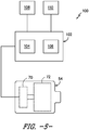
- control system 100 for controlling an electric aspirator of an air intake system is illustrated in accordance with aspects of the present subject matter.
- the control system 100 will be described herein with reference to the air intake system 30 and the electric aspirator 54 described above with reference to FIGS. 2-4 .
- the disclosed control system 100 may generally be utilized with any other suitable air intake system and/or any other suitable electric aspirator.
- the control system 100 may generally include a controller 102 communicatively coupled to the electric aspirator 54 so as to allow the controller 102 to electronically control the operation of the aspirator 54.
- the controller 102 may be configured to control the rotational speed of the motor 70 based on one or more load-related parameters of the work vehicle 10. For instance, as will be described below, in one embodiment, the rotational speed of the motor 70 may be reduced at lower engine loads and increased at higher engine loads. As such, the electric aspirator 54 may require less energy to be operated at reduced loads, thereby saving on fuel efficiency. In addition, such reduced speeds may result in lower intake restriction within the system at the reduced engine loads.
- the controller 102 may comprise any suitable processor-based device known in the art, such as a computing device or any suitable combination of computing devices.
- the controller 102 may include one or more processor(s) 104 and associated memory device(s) 106 configured to perform a variety of computer-implemented functions.
- processor refers not only to integrated circuits referred to in the art as being included in a computer, but also refers to a controller, a microcontroller, a microcomputer, a programmable logic controller (PLC), an application specific integrated circuit, and other programmable circuits.
- the memory device(s) 106 of the controller 102 may generally comprise memory element(s) including, but are not limited to, computer readable medium (e.g., random access memory (RAM)), computer readable non-volatile medium (e.g., a flash memory), a floppy disk, a compact disc-read only memory (CD-ROM), a magneto-optical disk (MOD), a digital versatile disc (DVD) and/or other suitable memory elements.
- Such memory device(s) 106 may generally be configured to store suitable computer-readable instructions that, when implemented by the processor(s) 104, configure the controller 102 to perform various computer-implemented functions, such as the computer-implemented method(s) described herein.
- the controller 102 may also include various other suitable components, such as a communications circuit or module, one or more input/output channels, a data/control bus and/or the like.
- the load-based parameter used to vary the rotational speed of the aspirator motor 70 may correspond to an air intake flow into the engine 22.
- the required air flow into the engine 22 must also be increased.
- FIG. 6 illustrates an example relationship between the engine load and the corresponding air intake flow as a function of engine speed (in RPM). As shown in FIG. 6 , as the engine load increases between zero load and a full or 100% load at each engine speed, the air flow into the engine 22 must be correspondingly increased.
- the controller 102 may be communicatively coupled to one or more flow sensor(s) 108 (e.g., one or more mass flow sensors).
- a flow sensor(s) 108 may be mounted to and/or within the conduit 50 extending between the filter assembly 32 and the engine 22 so as to be in flow communication with the cleaned intake air flowing into the engine 22.
- the flow sensor(s) 108 may be positioned at any other suitable location and/or associated with any other suitable vehicle component that allows air intake flow to be monitored.
- a flow sensor(s) 108 (shown in dashed lines) may be positioned at a location within the engine 22 in order to monitor the air intake flow.
- the controller 102 may be configured to utilize the air intake flow calculations associated with the engine control as the basis for estimating or determining the amount of air flowing into the engine 22.
- the controller 102 or a separate controller communicatively coupled to the controller 102 may be configured to calculate the required intake flow for the engine 22 based on numerous factors, such as the commanded engine speed, the engine load, etc.
- the calculated intake flow may then be utilized by the controller 102 as the associated input for varying the operating speed of the aspirator motor 70.
- the mathematical relationship(s) for calculating the required intake flow for the engine 22 is well known in the art and, thus, will not be described in any detail herein.
- the controller 102 may, in turn, be configured to vary the rotational speed of the aspirator motor 70 in a manner that provides for efficient and effective aspiration of the pre-cleaner 36 at all engine loads while allowing for reduced energy requirements at lower engine loads.
- the inventors of the present subject matter have found that the most effective pre-cleaner aspiration typically occurs when a given percentage of the engine's intake flow is scavenged through the pre-cleaner port 46 via the aspirator 54.
- effective pre-cleaner aspiration occurs when about 5% to about 15% of the air intake flow is scavenged through the outlet port 46, such as from about 7% to about 13% of the air intake flow or about 9% to about 11% of the air intake flow and/or any other subranges therebetween.
- the controller 102 may be able to control the operation of the aspirator 54 so as to optimize the performance of the entire air intake system 30.
- FIG. 7 illustrates an example graph charting the air intake flow (along the x-axis), the rotational speed of the aspirator motor 70 (along the left vertical axis) and the flow restriction at the pre-cleaner outlet port 46 (along the right vertical axis).
- the rotational speed of the aspirator motor 70 must be correspondingly increased to ensure that the required percentage of air is scavenged from the pre-cleaner 36.
- the correlation between the air intake flow and the required rotational speed of the aspirator motor 70 shown in FIG. 7 is only illustrated to provide one example of such a relationship.
- the specific correlation between such variables may generally vary depending on the specific configuration of the air intake system being used.
- the correlation may generally be determined using any suitable analytical methodology known in the art. For instance, in one embodiment, the correlation may be determined experimentally, such as by monitoring the amount of air scavenged from the pre-cleaner 36 at differing motor speeds and at differing air flow rates through the specific air intake system being used.
- the correlation may be determined by modelling the air intake system using suitable modeling and/or analysis software.
- correlation may be stored or otherwise made accessible to the controller 102 in any suitable format and/or using any suitable means.
- a data or look-up table may be stored within the controller's memory 106 that correlates the air intake flow to the motor speed.
- the controller 102 may refer to the stored table to determine the speed at which the aspirator motor must be rotated in order to scavenge the required airflow percentage.
- the capacity and/or specifications for the aspirator motor 70 may be selected so as to ensure that the aspirator 54 is capable of scavenging the required percentage of the air intake flow at the highest potential engine loads (and, thus, the highest potential air intake flows).
- the aspirator motor 70 may be selected such that, at its maximum rotational speed, the aspirator 54 is capable of scavenging at least the required airflow percentage when the air intake flow into the engine 22 is maximized.
- any other suitable load-related parameters may be used as a basis for adjusting the rotational speed of the aspirator motor 70.
- the rotational speed may be varied based on a pressure differential across the filter assembly 32.
- a suitable pressure sensor(s) (not shown) may be disposed upstream and downstream of the filter assembly 32 in order to monitor the pressure of the corresponding air intake flow.
- the controller 102 may be configured to receive the pressure measurements and, based upon the pressure differential across the filter assembly 32, vary the speed of the aspirator motor 70.
- the operation of the aspirator 54 may be controlled as a function of any other suitable parameter or operating condition of the work vehicle 10.
- the operation of the aspirator 54 may be controlled based on the amount of dust and/or other particulates contained within the air flowing into the air intake system 30.
- a suitable particulate sensor(s) 110 may be positioned upstream of the filter assembly 32 for monitoring the amount of particulates contained within the intake air flow.
- a particulate sensor(s) 108 may be positioned at or adjacent to the inlet of the intake duct 34.
- the particulate sensor(s) 110 may be communicatively coupled to the controller 102 (e.g., as shown in FIG. 5 ).
- the controller 102 may be configured to control the operation of the aspirator 54 based on the particulate concentration measurements provided by the particulate sensor(s) 110.
- the controller 102 may be configured to control the operation of the aspirator 54 based on the amount of particulates contained within the intake air in accordance with any suitable control methodology.
- the particulate-based measurements may be used in combination with the load-based variable speed control described above.
- the controller 102 may be configured to vary the rotational speed of the aspirator motor 70 as a function of the load-based parameter as long as the particulate sensor(s) 110 detects any amount of particulates within the incoming air.
- the controller 102 may be configured to turn off or shut down the aspirator 54 until particulates are once again detected by the particulate sensor(s) 110.
- the controller 102 may be configured to control the operation of the aspirator 54 based solely on the amount of particulates contained within the intake air.
- the controller 102 may be configured to vary the rotational speed of the aspirator motor 70 as a function of the particulate concentration, such as by increasing the rotational speed with increases in the amount of particulates contained within the incoming air and/or by decreasing the rotational speed with decreases in the amount of particulates contained within the incoming air.
- the particulate sensor(s) 110 may generally correspond to any suitable sensor(s) known in the art that allows for particulates to be detected within the air flowing into and/or through the air intake system 30.
- the particulate sensor(s) 110 may correspond to one or more light sensors positioned within the intake duct 34, such as within a snorkel (not shown) of the intake duct 34.
- the particulate sensor(s) 110 may be configured to detect the presence of particulates within the air by detecting light reflected off of the particulates as such particulates flow into and/or through the intake duct 34.
- the present subject matter is also directed to a method for controlling an electric aspirator of an air intake system.
- the method may include applying a vacuum via the electric aspirator 54 to a pre-cleaner outlet 46 for scavenging particulates separated from the intake air within the pre-cleaner 36, monitoring a load-based parameter of the work vehicle 10 (e.g., the intake airflow) and varying a rotational speed of the aspirator motor 70 based on changes in the load-based parameter.
Landscapes
- Engineering & Computer Science (AREA)
- Chemical & Material Sciences (AREA)
- Combustion & Propulsion (AREA)
- Mechanical Engineering (AREA)
- General Engineering & Computer Science (AREA)
- Chemical Kinetics & Catalysis (AREA)
- Filtering Of Dispersed Particles In Gases (AREA)
- Combined Means For Separation Of Solids (AREA)
- Processes For Solid Components From Exhaust (AREA)
Applications Claiming Priority (1)
| Application Number | Priority Date | Filing Date | Title |
|---|---|---|---|
| US14/291,978 US9273649B2 (en) | 2014-05-30 | 2014-05-30 | System and method for controlling an electric aspirator of an air intake system for a work vehicle |
Publications (2)
| Publication Number | Publication Date |
|---|---|
| EP2949912A1 EP2949912A1 (en) | 2015-12-02 |
| EP2949912B1 true EP2949912B1 (en) | 2019-04-24 |
Family
ID=53510580
Family Applications (1)
| Application Number | Title | Priority Date | Filing Date |
|---|---|---|---|
| EP15169685.3A Active EP2949912B1 (en) | 2014-05-30 | 2015-05-28 | System and method for controlling an electric aspirator of an air intake system for a work vehicle |
Country Status (4)
| Country | Link |
|---|---|
| US (1) | US9273649B2 (pt) |
| EP (1) | EP2949912B1 (pt) |
| CN (1) | CN105317594B (pt) |
| BR (1) | BR102015011969B1 (pt) |
Families Citing this family (19)
| Publication number | Priority date | Publication date | Assignee | Title |
|---|---|---|---|---|
| US10668414B2 (en) | 2014-07-23 | 2020-06-02 | Cummins Filtration Ip, Inc. | Intake bypass flow management systems and methods |
| EP3193005B1 (en) * | 2016-01-15 | 2018-12-12 | AGCO International GmbH | A pre-filter system for a vehicle |
| WO2017196367A1 (en) * | 2016-05-13 | 2017-11-16 | Cummins Filtration Ip, Inc. | Inertial precleaner with variable aspiration flowrate control via ambient dust concentration sensor input |
| CN108019305B (zh) * | 2016-10-28 | 2020-10-02 | 长城汽车股份有限公司 | 进气系统以及车辆 |
| EP3401539A1 (en) * | 2017-05-09 | 2018-11-14 | AGCO International GmbH | An agricultural vehicle air cleaner assembly |
| SE541282C3 (en) * | 2017-09-05 | 2019-07-16 | Husqvarna Ab | Separator and method of operating a separator |
| SE541077C2 (en) * | 2017-09-05 | 2019-03-26 | Husqvarna Ab | Separator, separator system and methods of their operation |
| US10543443B2 (en) * | 2017-12-13 | 2020-01-28 | Caterpillar Inc. | Air intake system for engines |
| IL257991B (en) | 2018-03-08 | 2021-09-30 | Beth El Zikhron Yaaqov Ind Ltd | Air filter with shutter for waste removal |
| CN109404180A (zh) * | 2018-12-12 | 2019-03-01 | 扬州盛达特种车有限公司 | 一种矿用车用带反吹的进气系统 |
| US10753322B1 (en) * | 2019-02-13 | 2020-08-25 | Deere & Company | Direct drive aspiration system |
| US10688861B1 (en) * | 2019-03-19 | 2020-06-23 | Cnh Industrial America Llc | Engine airflow adjustment system |
| US20220161177A1 (en) * | 2019-03-29 | 2022-05-26 | Donaldson Company, Inc. | Air cleaner bypass assembly and method of operating |
| AU2020378250A1 (en) * | 2019-11-05 | 2022-05-26 | Parker-Hannifin Corporation | Air flow distribution arrangements in pre-cleaner systems |
| US11555472B2 (en) * | 2019-12-23 | 2023-01-17 | Caterpillar Inc. | Siloxane mitigation in machine system having blower for pressure drop compensation |
| DE102020200945A1 (de) * | 2020-01-27 | 2021-07-29 | Deere & Company | Luftfiltersystem für ein Nutzfahrzeug |
| EP3865199B1 (de) * | 2020-02-12 | 2023-09-13 | Carl Freudenberg KG | Filtermodul mit sensor zur bestimmung des beladungszustandes und verfahren zum bestimmen des beladungszustandes |
| US20230116444A1 (en) * | 2020-02-28 | 2023-04-13 | Cummins Filtration Inc. | Particulate matter evacuation pump |
| TWM614198U (zh) * | 2020-05-06 | 2021-07-11 | 基利爾 庫勒卡斯基 | 管狀過濾器及用於過濾受污染的環境空氣之系統 |
Family Cites Families (43)
| Publication number | Priority date | Publication date | Assignee | Title |
|---|---|---|---|---|
| US3469566A (en) | 1967-01-19 | 1969-09-30 | Hastings Mfg Co | Centrifugal air precleaner with blower |
| US3696666A (en) | 1969-10-15 | 1972-10-10 | Donaldson Co Inc | Dust leak detector for air cleaner systems |
| US3656303A (en) | 1970-04-13 | 1972-04-18 | Robert C La Force | Combustion engine pollution control |
| US4135897A (en) | 1976-05-13 | 1979-01-23 | Gondek John T | Air cleaner |
| DE2738293A1 (de) * | 1977-08-25 | 1979-03-01 | Motoren Turbinen Union | Luftfiltereinrichtung |
| US4218223A (en) * | 1977-11-25 | 1980-08-19 | Donaldson Company, Inc. | Pre-cleaner for combustion engines |
| US4331459A (en) | 1980-10-10 | 1982-05-25 | Donaldson Company, Inc. | Self-cleaning pulsed air cleaner |
| DE3152436A1 (en) | 1980-10-10 | 1982-12-30 | Donaldson Co Inc | Self-cleaning pulsed air cleaner |
| US4482365A (en) * | 1982-03-01 | 1984-11-13 | Pall Corporation | Vortex air cleaner and self-cleaning barrier filter assembly for supercharged engines |
| US4514193A (en) | 1984-07-26 | 1985-04-30 | Donaldson Company, Inc. | Self-cleaning air cleaner assembly with rotating filter element and inertial pre-cleaner |
| DE4109406C1 (pt) | 1991-03-22 | 1992-04-23 | Mercedes-Benz Aktiengesellschaft, 7000 Stuttgart, De | |
| US5401285A (en) * | 1993-09-17 | 1995-03-28 | Donaldson Company, Inc. | Air cleaner having scavenger arrangement for precleaner and filter thereof |
| US5613992A (en) | 1994-11-23 | 1997-03-25 | Donaldson Company, Inc. | Reverse flow air filter arrangement and method |
| SE522112C2 (sv) * | 1997-09-22 | 2004-01-13 | Volvo Car Corp | Förfarande och anordning för bestämning av temperaturvärden hos materialet i åtminstone en temperaturkritisk komponent |
| US6800117B2 (en) | 2000-09-05 | 2004-10-05 | Donaldson Company, Inc. | Filtration arrangement utilizing pleated construction and method |
| US6588524B2 (en) | 2001-05-31 | 2003-07-08 | Deere & Company | Vacuum pump aspirator for work vehicle pre-cleaner |
| DE10158569A1 (de) | 2001-11-29 | 2003-06-12 | Bosch Gmbh Robert | Verfahren und Anordnung zur Regeneration von Dieselpartikelfiltern |
| AU2003252127B2 (en) | 2002-07-25 | 2009-06-18 | Kammel, Refaat A | System and method for reducting pollutants from diesel engine exhaust |
| US6878189B2 (en) | 2003-04-30 | 2005-04-12 | James G. Moredock | Air precleaner and method for separating heavier-than-air particulate debris from debris laden air |
| WO2007095675A1 (en) | 2006-02-20 | 2007-08-30 | Xtralis Pty Ltd | In-line smoke attenuator |
| EP2708273B1 (en) | 2006-06-19 | 2019-03-20 | Donaldson Company, Inc. | Air cleaner with pulse jet reverse cleaning |
| US20080178592A1 (en) * | 2007-01-25 | 2008-07-31 | Christopher Adam Bering | Pre-cleaner aspiration system |
| JP5174547B2 (ja) | 2007-07-10 | 2013-04-03 | ヤマハ発動機株式会社 | 吸気システムおよびそれを備えた自動二輪車 |
| FR2919811B1 (fr) | 2007-08-08 | 2010-10-15 | Saint Gobain Quartz Sas | Media pour filtre photocatalytique |
| WO2009051859A2 (en) | 2007-10-18 | 2009-04-23 | Deere & Company | Controlled flow air precleaner |
| US8007565B2 (en) | 2007-10-23 | 2011-08-30 | The Sy-Klone Company | Powered air cleaning system and air cleaning method |
| CA2718531C (en) | 2008-03-20 | 2017-01-03 | Donaldson Company, Inc. | Evacuation valve arrangements; pulse jet air cleaner systems using same; and, methods |
| GB0809111D0 (en) | 2008-05-20 | 2008-06-25 | Agco Sa | Air filter system |
| US7878171B2 (en) * | 2008-06-17 | 2011-02-01 | Deere & Company | Engine cooling flow debris cleaner and air pre-cleaner aspirator |
| DE102008056938B4 (de) | 2008-08-22 | 2014-01-02 | Oliver Frieters | Entstaubungsanlage mit Luft-Rückführung und Reststaubmessung sowie Steuerungsverfahren hierfür |
| US20100071978A1 (en) | 2008-09-22 | 2010-03-25 | Clark Equipment Company | Combustion air cleaner scavenge system |
| US8151774B2 (en) | 2009-05-13 | 2012-04-10 | Deere & Company | Engine combustion air cyclonic pre-cleaner embodying throttling member adjusted in accordance with engine load |
| US8925520B2 (en) | 2010-03-10 | 2015-01-06 | Ford Global Technologies, Llc | Intake system including vacuum aspirator |
| FR2969931A1 (fr) | 2011-01-03 | 2012-07-06 | Air Liquide Welding France | Unite et procede de filtrage d'air, notamment de fumees de soudage |
| WO2012171005A1 (en) | 2011-06-10 | 2012-12-13 | Kah Jr Carl L C | Wet/dry, non-porous bag/bagless vacuum assembly with steam and variable speed settable vacuum motor control with no loss of suction |
| US8657928B2 (en) | 2011-07-29 | 2014-02-25 | The Sy-Klone Company | Versatile compact air precleaner, air cleaning method and disposable air filter cartridge for air precleaner |
| DE102011121630B4 (de) * | 2011-12-20 | 2013-09-26 | Mann + Hummel Gmbh | Filtereinrichtung und Ansaugsystem |
| US8783231B2 (en) | 2012-03-12 | 2014-07-22 | Ford Global Technologies, Llc | Venturi for vapor purge |
| US9027343B2 (en) | 2012-06-14 | 2015-05-12 | Ford Global Technologies, Llc | Approach for supplying vacuum via a supercharger |
| US9097149B2 (en) | 2012-07-13 | 2015-08-04 | Ford Global Technologies, Llc | Aspirator for crankcase ventilation and vacuum generation |
| WO2014077938A1 (en) * | 2012-11-14 | 2014-05-22 | Cnh America Llc | Air intake system for a work vehicle |
| WO2014210534A1 (en) * | 2013-06-28 | 2014-12-31 | Donaldson Company, Inc. | Air intake arrangement for engine and methods |
| US9273648B2 (en) * | 2013-07-26 | 2016-03-01 | Cnh Industrial America Llc | Air intake system for a work vehicle |
-
2014
- 2014-05-30 US US14/291,978 patent/US9273649B2/en active Active
-
2015
- 2015-05-25 BR BR102015011969-0A patent/BR102015011969B1/pt active IP Right Grant
- 2015-05-28 EP EP15169685.3A patent/EP2949912B1/en active Active
- 2015-05-29 CN CN201510284259.8A patent/CN105317594B/zh active Active
Non-Patent Citations (1)
| Title |
|---|
| None * |
Also Published As
| Publication number | Publication date |
|---|---|
| CN105317594A (zh) | 2016-02-10 |
| US9273649B2 (en) | 2016-03-01 |
| CN105317594B (zh) | 2019-12-13 |
| BR102015011969B1 (pt) | 2022-06-14 |
| US20150345439A1 (en) | 2015-12-03 |
| BR102015011969A2 (pt) | 2016-01-05 |
| EP2949912A1 (en) | 2015-12-02 |
Similar Documents
| Publication | Publication Date | Title |
|---|---|---|
| EP2949912B1 (en) | System and method for controlling an electric aspirator of an air intake system for a work vehicle | |
| EP2920451B1 (en) | Air intake system for a work vehicle | |
| EP2829716B1 (en) | Air intake system for a work vehicle | |
| EP2136066B1 (en) | Engine cooling flow debris cleaner and air pre-cleaner aspirator | |
| EP2907998B1 (en) | Air intake system for a work vehicle with improved fan aspiration. | |
| US20150240760A1 (en) | Snorkel intake dirt inertial separator for internal combustion engine | |
| BRPI0901624B1 (pt) | sistema de motor de combustão interna, e, máquina mecânica que opera em um ambiente significativamente carregado de contaminantes | |
| EP2907996A1 (en) | Under-hood mounting configuration for a control unit of a work vehicle | |
| EP3401539A1 (en) | An agricultural vehicle air cleaner assembly | |
| EP3014097B1 (en) | Air intake arrangement for engine | |
| EP3034830B1 (en) | Engine air pre cleaner evacuation system for work machine | |
| EP3193005A1 (en) | A pre-filter system for a vehicle | |
| US20240042368A1 (en) | Self-Cleaning Air Filter System | |
| CN112407960A (zh) | 一种负压抽吸系统、负压抽吸系统的控制方法及车载设备 | |
| CN202715322U (zh) | 具滤网油污累积侦测装置的油雾过滤机 | |
| SE538986C2 (sv) | Arrangemang i samband med luftfilter | |
| CN102772957A (zh) | 一种带自动除尘装置的空滤器 | |
| CN107073372B (zh) | 油雾捕集装置 | |
| KR20100003110U (ko) | 인버터 집진기 | |
| JP2023518270A (ja) | 能動的なプレクリーナシステム及び使用方法 | |
| JP2006513855A (ja) | 動力式空気清浄システムおよび清浄方法 |
Legal Events
| Date | Code | Title | Description |
|---|---|---|---|
| AK | Designated contracting states |
Kind code of ref document: A1 Designated state(s): AL AT BE BG CH CY CZ DE DK EE ES FI FR GB GR HR HU IE IS IT LI LT LU LV MC MK MT NL NO PL PT RO RS SE SI SK SM TR |
|
| AX | Request for extension of the european patent |
Extension state: BA ME |
|
| PUAI | Public reference made under article 153(3) epc to a published international application that has entered the european phase |
Free format text: ORIGINAL CODE: 0009012 |
|
| 17P | Request for examination filed |
Effective date: 20160602 |
|
| RBV | Designated contracting states (corrected) |
Designated state(s): AL AT BE BG CH CY CZ DE DK EE ES FI FR GB GR HR HU IE IS IT LI LT LU LV MC MK MT NL NO PL PT RO RS SE SI SK SM TR |
|
| STAA | Information on the status of an ep patent application or granted ep patent |
Free format text: STATUS: EXAMINATION IS IN PROGRESS |
|
| 17Q | First examination report despatched |
Effective date: 20180508 |
|
| GRAP | Despatch of communication of intention to grant a patent |
Free format text: ORIGINAL CODE: EPIDOSNIGR1 |
|
| STAA | Information on the status of an ep patent application or granted ep patent |
Free format text: STATUS: GRANT OF PATENT IS INTENDED |
|
| INTG | Intention to grant announced |
Effective date: 20181122 |
|
| GRAS | Grant fee paid |
Free format text: ORIGINAL CODE: EPIDOSNIGR3 |
|
| GRAA | (expected) grant |
Free format text: ORIGINAL CODE: 0009210 |
|
| STAA | Information on the status of an ep patent application or granted ep patent |
Free format text: STATUS: THE PATENT HAS BEEN GRANTED |
|
| AK | Designated contracting states |
Kind code of ref document: B1 Designated state(s): AL AT BE BG CH CY CZ DE DK EE ES FI FR GB GR HR HU IE IS IT LI LT LU LV MC MK MT NL NO PL PT RO RS SE SI SK SM TR |
|
| REG | Reference to a national code |
Ref country code: GB Ref legal event code: FG4D |
|
| REG | Reference to a national code |
Ref country code: CH Ref legal event code: EP |
|
| REG | Reference to a national code |
Ref country code: AT Ref legal event code: REF Ref document number: 1124453 Country of ref document: AT Kind code of ref document: T Effective date: 20190515 Ref country code: IE Ref legal event code: FG4D |
|
| REG | Reference to a national code |
Ref country code: DE Ref legal event code: R096 Ref document number: 602015028727 Country of ref document: DE |
|
| REG | Reference to a national code |
Ref country code: NL Ref legal event code: MP Effective date: 20190424 |
|
| REG | Reference to a national code |
Ref country code: LT Ref legal event code: MG4D |
|
| PG25 | Lapsed in a contracting state [announced via postgrant information from national office to epo] |
Ref country code: NL Free format text: LAPSE BECAUSE OF FAILURE TO SUBMIT A TRANSLATION OF THE DESCRIPTION OR TO PAY THE FEE WITHIN THE PRESCRIBED TIME-LIMIT Effective date: 20190424 |
|
| PG25 | Lapsed in a contracting state [announced via postgrant information from national office to epo] |
Ref country code: LT Free format text: LAPSE BECAUSE OF FAILURE TO SUBMIT A TRANSLATION OF THE DESCRIPTION OR TO PAY THE FEE WITHIN THE PRESCRIBED TIME-LIMIT Effective date: 20190424 Ref country code: HR Free format text: LAPSE BECAUSE OF FAILURE TO SUBMIT A TRANSLATION OF THE DESCRIPTION OR TO PAY THE FEE WITHIN THE PRESCRIBED TIME-LIMIT Effective date: 20190424 Ref country code: ES Free format text: LAPSE BECAUSE OF FAILURE TO SUBMIT A TRANSLATION OF THE DESCRIPTION OR TO PAY THE FEE WITHIN THE PRESCRIBED TIME-LIMIT Effective date: 20190424 Ref country code: SE Free format text: LAPSE BECAUSE OF FAILURE TO SUBMIT A TRANSLATION OF THE DESCRIPTION OR TO PAY THE FEE WITHIN THE PRESCRIBED TIME-LIMIT Effective date: 20190424 Ref country code: NO Free format text: LAPSE BECAUSE OF FAILURE TO SUBMIT A TRANSLATION OF THE DESCRIPTION OR TO PAY THE FEE WITHIN THE PRESCRIBED TIME-LIMIT Effective date: 20190724 Ref country code: PT Free format text: LAPSE BECAUSE OF FAILURE TO SUBMIT A TRANSLATION OF THE DESCRIPTION OR TO PAY THE FEE WITHIN THE PRESCRIBED TIME-LIMIT Effective date: 20190824 Ref country code: FI Free format text: LAPSE BECAUSE OF FAILURE TO SUBMIT A TRANSLATION OF THE DESCRIPTION OR TO PAY THE FEE WITHIN THE PRESCRIBED TIME-LIMIT Effective date: 20190424 Ref country code: AL Free format text: LAPSE BECAUSE OF FAILURE TO SUBMIT A TRANSLATION OF THE DESCRIPTION OR TO PAY THE FEE WITHIN THE PRESCRIBED TIME-LIMIT Effective date: 20190424 |
|
| PG25 | Lapsed in a contracting state [announced via postgrant information from national office to epo] |
Ref country code: BG Free format text: LAPSE BECAUSE OF FAILURE TO SUBMIT A TRANSLATION OF THE DESCRIPTION OR TO PAY THE FEE WITHIN THE PRESCRIBED TIME-LIMIT Effective date: 20190724 Ref country code: PL Free format text: LAPSE BECAUSE OF FAILURE TO SUBMIT A TRANSLATION OF THE DESCRIPTION OR TO PAY THE FEE WITHIN THE PRESCRIBED TIME-LIMIT Effective date: 20190424 Ref country code: GR Free format text: LAPSE BECAUSE OF FAILURE TO SUBMIT A TRANSLATION OF THE DESCRIPTION OR TO PAY THE FEE WITHIN THE PRESCRIBED TIME-LIMIT Effective date: 20190725 Ref country code: LV Free format text: LAPSE BECAUSE OF FAILURE TO SUBMIT A TRANSLATION OF THE DESCRIPTION OR TO PAY THE FEE WITHIN THE PRESCRIBED TIME-LIMIT Effective date: 20190424 Ref country code: RS Free format text: LAPSE BECAUSE OF FAILURE TO SUBMIT A TRANSLATION OF THE DESCRIPTION OR TO PAY THE FEE WITHIN THE PRESCRIBED TIME-LIMIT Effective date: 20190424 |
|
| REG | Reference to a national code |
Ref country code: AT Ref legal event code: MK05 Ref document number: 1124453 Country of ref document: AT Kind code of ref document: T Effective date: 20190424 |
|
| REG | Reference to a national code |
Ref country code: CH Ref legal event code: PL |
|
| PG25 | Lapsed in a contracting state [announced via postgrant information from national office to epo] |
Ref country code: IS Free format text: LAPSE BECAUSE OF FAILURE TO SUBMIT A TRANSLATION OF THE DESCRIPTION OR TO PAY THE FEE WITHIN THE PRESCRIBED TIME-LIMIT Effective date: 20190824 |
|
| REG | Reference to a national code |
Ref country code: DE Ref legal event code: R097 Ref document number: 602015028727 Country of ref document: DE |
|
| PG25 | Lapsed in a contracting state [announced via postgrant information from national office to epo] |
Ref country code: LI Free format text: LAPSE BECAUSE OF NON-PAYMENT OF DUE FEES Effective date: 20190531 Ref country code: SK Free format text: LAPSE BECAUSE OF FAILURE TO SUBMIT A TRANSLATION OF THE DESCRIPTION OR TO PAY THE FEE WITHIN THE PRESCRIBED TIME-LIMIT Effective date: 20190424 Ref country code: RO Free format text: LAPSE BECAUSE OF FAILURE TO SUBMIT A TRANSLATION OF THE DESCRIPTION OR TO PAY THE FEE WITHIN THE PRESCRIBED TIME-LIMIT Effective date: 20190424 Ref country code: CH Free format text: LAPSE BECAUSE OF NON-PAYMENT OF DUE FEES Effective date: 20190531 Ref country code: CZ Free format text: LAPSE BECAUSE OF FAILURE TO SUBMIT A TRANSLATION OF THE DESCRIPTION OR TO PAY THE FEE WITHIN THE PRESCRIBED TIME-LIMIT Effective date: 20190424 Ref country code: MC Free format text: LAPSE BECAUSE OF FAILURE TO SUBMIT A TRANSLATION OF THE DESCRIPTION OR TO PAY THE FEE WITHIN THE PRESCRIBED TIME-LIMIT Effective date: 20190424 Ref country code: AT Free format text: LAPSE BECAUSE OF FAILURE TO SUBMIT A TRANSLATION OF THE DESCRIPTION OR TO PAY THE FEE WITHIN THE PRESCRIBED TIME-LIMIT Effective date: 20190424 Ref country code: DK Free format text: LAPSE BECAUSE OF FAILURE TO SUBMIT A TRANSLATION OF THE DESCRIPTION OR TO PAY THE FEE WITHIN THE PRESCRIBED TIME-LIMIT Effective date: 20190424 Ref country code: EE Free format text: LAPSE BECAUSE OF FAILURE TO SUBMIT A TRANSLATION OF THE DESCRIPTION OR TO PAY THE FEE WITHIN THE PRESCRIBED TIME-LIMIT Effective date: 20190424 |
|
| REG | Reference to a national code |
Ref country code: BE Ref legal event code: MM Effective date: 20190531 |
|
| PG25 | Lapsed in a contracting state [announced via postgrant information from national office to epo] |
Ref country code: LU Free format text: LAPSE BECAUSE OF NON-PAYMENT OF DUE FEES Effective date: 20190528 Ref country code: SM Free format text: LAPSE BECAUSE OF FAILURE TO SUBMIT A TRANSLATION OF THE DESCRIPTION OR TO PAY THE FEE WITHIN THE PRESCRIBED TIME-LIMIT Effective date: 20190424 |
|
| PLBE | No opposition filed within time limit |
Free format text: ORIGINAL CODE: 0009261 |
|
| STAA | Information on the status of an ep patent application or granted ep patent |
Free format text: STATUS: NO OPPOSITION FILED WITHIN TIME LIMIT |
|
| PG25 | Lapsed in a contracting state [announced via postgrant information from national office to epo] |
Ref country code: TR Free format text: LAPSE BECAUSE OF FAILURE TO SUBMIT A TRANSLATION OF THE DESCRIPTION OR TO PAY THE FEE WITHIN THE PRESCRIBED TIME-LIMIT Effective date: 20190424 |
|
| 26N | No opposition filed |
Effective date: 20200127 |
|
| PG25 | Lapsed in a contracting state [announced via postgrant information from national office to epo] |
Ref country code: IE Free format text: LAPSE BECAUSE OF NON-PAYMENT OF DUE FEES Effective date: 20190528 |
|
| PG25 | Lapsed in a contracting state [announced via postgrant information from national office to epo] |
Ref country code: BE Free format text: LAPSE BECAUSE OF NON-PAYMENT OF DUE FEES Effective date: 20190531 Ref country code: SI Free format text: LAPSE BECAUSE OF FAILURE TO SUBMIT A TRANSLATION OF THE DESCRIPTION OR TO PAY THE FEE WITHIN THE PRESCRIBED TIME-LIMIT Effective date: 20190424 |
|
| PG25 | Lapsed in a contracting state [announced via postgrant information from national office to epo] |
Ref country code: FR Free format text: LAPSE BECAUSE OF NON-PAYMENT OF DUE FEES Effective date: 20190624 |
|
| PG25 | Lapsed in a contracting state [announced via postgrant information from national office to epo] |
Ref country code: CY Free format text: LAPSE BECAUSE OF FAILURE TO SUBMIT A TRANSLATION OF THE DESCRIPTION OR TO PAY THE FEE WITHIN THE PRESCRIBED TIME-LIMIT Effective date: 20190424 |
|
| PG25 | Lapsed in a contracting state [announced via postgrant information from national office to epo] |
Ref country code: MT Free format text: LAPSE BECAUSE OF FAILURE TO SUBMIT A TRANSLATION OF THE DESCRIPTION OR TO PAY THE FEE WITHIN THE PRESCRIBED TIME-LIMIT Effective date: 20190424 Ref country code: HU Free format text: LAPSE BECAUSE OF FAILURE TO SUBMIT A TRANSLATION OF THE DESCRIPTION OR TO PAY THE FEE WITHIN THE PRESCRIBED TIME-LIMIT; INVALID AB INITIO Effective date: 20150528 |
|
| PG25 | Lapsed in a contracting state [announced via postgrant information from national office to epo] |
Ref country code: MK Free format text: LAPSE BECAUSE OF FAILURE TO SUBMIT A TRANSLATION OF THE DESCRIPTION OR TO PAY THE FEE WITHIN THE PRESCRIBED TIME-LIMIT Effective date: 20190424 |
|
| PGFP | Annual fee paid to national office [announced via postgrant information from national office to epo] |
Ref country code: IT Payment date: 20230511 Year of fee payment: 9 Ref country code: DE Payment date: 20230525 Year of fee payment: 9 |
|
| PGFP | Annual fee paid to national office [announced via postgrant information from national office to epo] |
Ref country code: GB Payment date: 20230526 Year of fee payment: 9 |