EP2949502A1 - Method for limiting vehicle speed at time of evasive travel, and vehicle - Google Patents
Method for limiting vehicle speed at time of evasive travel, and vehicle Download PDFInfo
- Publication number
- EP2949502A1 EP2949502A1 EP13872800.1A EP13872800A EP2949502A1 EP 2949502 A1 EP2949502 A1 EP 2949502A1 EP 13872800 A EP13872800 A EP 13872800A EP 2949502 A1 EP2949502 A1 EP 2949502A1
- Authority
- EP
- European Patent Office
- Prior art keywords
- vehicle
- speed
- electric power
- battery
- regenerative
- Prior art date
- Legal status (The legal status is an assumption and is not a legal conclusion. Google has not performed a legal analysis and makes no representation as to the accuracy of the status listed.)
- Withdrawn
Links
- 238000000034 method Methods 0.000 title claims abstract description 12
- 230000001172 regenerating effect Effects 0.000 claims abstract description 51
- 230000003247 decreasing effect Effects 0.000 claims description 10
- 238000000926 separation method Methods 0.000 claims description 8
- 230000002159 abnormal effect Effects 0.000 abstract description 9
- 230000005856 abnormality Effects 0.000 description 10
- 238000012544 monitoring process Methods 0.000 description 4
- 230000007423 decrease Effects 0.000 description 3
- 238000005516 engineering process Methods 0.000 description 2
- 238000010248 power generation Methods 0.000 description 2
- 241000150258 Prospect Hill orthohantavirus Species 0.000 description 1
- 238000004891 communication Methods 0.000 description 1
- 238000007599 discharging Methods 0.000 description 1
- 230000000694 effects Effects 0.000 description 1
- 229920000218 poly(hydroxyvalerate) Polymers 0.000 description 1
Images


Classifications
-
- B—PERFORMING OPERATIONS; TRANSPORTING
- B60—VEHICLES IN GENERAL
- B60L—PROPULSION OF ELECTRICALLY-PROPELLED VEHICLES; SUPPLYING ELECTRIC POWER FOR AUXILIARY EQUIPMENT OF ELECTRICALLY-PROPELLED VEHICLES; ELECTRODYNAMIC BRAKE SYSTEMS FOR VEHICLES IN GENERAL; MAGNETIC SUSPENSION OR LEVITATION FOR VEHICLES; MONITORING OPERATING VARIABLES OF ELECTRICALLY-PROPELLED VEHICLES; ELECTRIC SAFETY DEVICES FOR ELECTRICALLY-PROPELLED VEHICLES
- B60L7/00—Electrodynamic brake systems for vehicles in general
- B60L7/10—Dynamic electric regenerative braking
- B60L7/14—Dynamic electric regenerative braking for vehicles propelled by AC motors
-
- B—PERFORMING OPERATIONS; TRANSPORTING
- B60—VEHICLES IN GENERAL
- B60L—PROPULSION OF ELECTRICALLY-PROPELLED VEHICLES; SUPPLYING ELECTRIC POWER FOR AUXILIARY EQUIPMENT OF ELECTRICALLY-PROPELLED VEHICLES; ELECTRODYNAMIC BRAKE SYSTEMS FOR VEHICLES IN GENERAL; MAGNETIC SUSPENSION OR LEVITATION FOR VEHICLES; MONITORING OPERATING VARIABLES OF ELECTRICALLY-PROPELLED VEHICLES; ELECTRIC SAFETY DEVICES FOR ELECTRICALLY-PROPELLED VEHICLES
- B60L15/00—Methods, circuits, or devices for controlling the traction-motor speed of electrically-propelled vehicles
- B60L15/20—Methods, circuits, or devices for controlling the traction-motor speed of electrically-propelled vehicles for control of the vehicle or its driving motor to achieve a desired performance, e.g. speed, torque, programmed variation of speed
- B60L15/2009—Methods, circuits, or devices for controlling the traction-motor speed of electrically-propelled vehicles for control of the vehicle or its driving motor to achieve a desired performance, e.g. speed, torque, programmed variation of speed for braking
-
- B—PERFORMING OPERATIONS; TRANSPORTING
- B60—VEHICLES IN GENERAL
- B60L—PROPULSION OF ELECTRICALLY-PROPELLED VEHICLES; SUPPLYING ELECTRIC POWER FOR AUXILIARY EQUIPMENT OF ELECTRICALLY-PROPELLED VEHICLES; ELECTRODYNAMIC BRAKE SYSTEMS FOR VEHICLES IN GENERAL; MAGNETIC SUSPENSION OR LEVITATION FOR VEHICLES; MONITORING OPERATING VARIABLES OF ELECTRICALLY-PROPELLED VEHICLES; ELECTRIC SAFETY DEVICES FOR ELECTRICALLY-PROPELLED VEHICLES
- B60L3/00—Electric devices on electrically-propelled vehicles for safety purposes; Monitoring operating variables, e.g. speed, deceleration or energy consumption
- B60L3/0023—Detecting, eliminating, remedying or compensating for drive train abnormalities, e.g. failures within the drive train
- B60L3/0046—Detecting, eliminating, remedying or compensating for drive train abnormalities, e.g. failures within the drive train relating to electric energy storage systems, e.g. batteries or capacitors
-
- B—PERFORMING OPERATIONS; TRANSPORTING
- B60—VEHICLES IN GENERAL
- B60L—PROPULSION OF ELECTRICALLY-PROPELLED VEHICLES; SUPPLYING ELECTRIC POWER FOR AUXILIARY EQUIPMENT OF ELECTRICALLY-PROPELLED VEHICLES; ELECTRODYNAMIC BRAKE SYSTEMS FOR VEHICLES IN GENERAL; MAGNETIC SUSPENSION OR LEVITATION FOR VEHICLES; MONITORING OPERATING VARIABLES OF ELECTRICALLY-PROPELLED VEHICLES; ELECTRIC SAFETY DEVICES FOR ELECTRICALLY-PROPELLED VEHICLES
- B60L3/00—Electric devices on electrically-propelled vehicles for safety purposes; Monitoring operating variables, e.g. speed, deceleration or energy consumption
- B60L3/0023—Detecting, eliminating, remedying or compensating for drive train abnormalities, e.g. failures within the drive train
- B60L3/0084—Detecting, eliminating, remedying or compensating for drive train abnormalities, e.g. failures within the drive train relating to control modules
-
- B—PERFORMING OPERATIONS; TRANSPORTING
- B60—VEHICLES IN GENERAL
- B60L—PROPULSION OF ELECTRICALLY-PROPELLED VEHICLES; SUPPLYING ELECTRIC POWER FOR AUXILIARY EQUIPMENT OF ELECTRICALLY-PROPELLED VEHICLES; ELECTRODYNAMIC BRAKE SYSTEMS FOR VEHICLES IN GENERAL; MAGNETIC SUSPENSION OR LEVITATION FOR VEHICLES; MONITORING OPERATING VARIABLES OF ELECTRICALLY-PROPELLED VEHICLES; ELECTRIC SAFETY DEVICES FOR ELECTRICALLY-PROPELLED VEHICLES
- B60L3/00—Electric devices on electrically-propelled vehicles for safety purposes; Monitoring operating variables, e.g. speed, deceleration or energy consumption
- B60L3/04—Cutting off the power supply under fault conditions
-
- B—PERFORMING OPERATIONS; TRANSPORTING
- B60—VEHICLES IN GENERAL
- B60L—PROPULSION OF ELECTRICALLY-PROPELLED VEHICLES; SUPPLYING ELECTRIC POWER FOR AUXILIARY EQUIPMENT OF ELECTRICALLY-PROPELLED VEHICLES; ELECTRODYNAMIC BRAKE SYSTEMS FOR VEHICLES IN GENERAL; MAGNETIC SUSPENSION OR LEVITATION FOR VEHICLES; MONITORING OPERATING VARIABLES OF ELECTRICALLY-PROPELLED VEHICLES; ELECTRIC SAFETY DEVICES FOR ELECTRICALLY-PROPELLED VEHICLES
- B60L3/00—Electric devices on electrically-propelled vehicles for safety purposes; Monitoring operating variables, e.g. speed, deceleration or energy consumption
- B60L3/08—Means for preventing excessive speed of the vehicle
-
- B—PERFORMING OPERATIONS; TRANSPORTING
- B60—VEHICLES IN GENERAL
- B60L—PROPULSION OF ELECTRICALLY-PROPELLED VEHICLES; SUPPLYING ELECTRIC POWER FOR AUXILIARY EQUIPMENT OF ELECTRICALLY-PROPELLED VEHICLES; ELECTRODYNAMIC BRAKE SYSTEMS FOR VEHICLES IN GENERAL; MAGNETIC SUSPENSION OR LEVITATION FOR VEHICLES; MONITORING OPERATING VARIABLES OF ELECTRICALLY-PROPELLED VEHICLES; ELECTRIC SAFETY DEVICES FOR ELECTRICALLY-PROPELLED VEHICLES
- B60L3/00—Electric devices on electrically-propelled vehicles for safety purposes; Monitoring operating variables, e.g. speed, deceleration or energy consumption
- B60L3/12—Recording operating variables ; Monitoring of operating variables
-
- B—PERFORMING OPERATIONS; TRANSPORTING
- B60—VEHICLES IN GENERAL
- B60L—PROPULSION OF ELECTRICALLY-PROPELLED VEHICLES; SUPPLYING ELECTRIC POWER FOR AUXILIARY EQUIPMENT OF ELECTRICALLY-PROPELLED VEHICLES; ELECTRODYNAMIC BRAKE SYSTEMS FOR VEHICLES IN GENERAL; MAGNETIC SUSPENSION OR LEVITATION FOR VEHICLES; MONITORING OPERATING VARIABLES OF ELECTRICALLY-PROPELLED VEHICLES; ELECTRIC SAFETY DEVICES FOR ELECTRICALLY-PROPELLED VEHICLES
- B60L58/00—Methods or circuit arrangements for monitoring or controlling batteries or fuel cells, specially adapted for electric vehicles
- B60L58/10—Methods or circuit arrangements for monitoring or controlling batteries or fuel cells, specially adapted for electric vehicles for monitoring or controlling batteries
- B60L58/12—Methods or circuit arrangements for monitoring or controlling batteries or fuel cells, specially adapted for electric vehicles for monitoring or controlling batteries responding to state of charge [SoC]
- B60L58/15—Preventing overcharging
-
- B—PERFORMING OPERATIONS; TRANSPORTING
- B60—VEHICLES IN GENERAL
- B60L—PROPULSION OF ELECTRICALLY-PROPELLED VEHICLES; SUPPLYING ELECTRIC POWER FOR AUXILIARY EQUIPMENT OF ELECTRICALLY-PROPELLED VEHICLES; ELECTRODYNAMIC BRAKE SYSTEMS FOR VEHICLES IN GENERAL; MAGNETIC SUSPENSION OR LEVITATION FOR VEHICLES; MONITORING OPERATING VARIABLES OF ELECTRICALLY-PROPELLED VEHICLES; ELECTRIC SAFETY DEVICES FOR ELECTRICALLY-PROPELLED VEHICLES
- B60L58/00—Methods or circuit arrangements for monitoring or controlling batteries or fuel cells, specially adapted for electric vehicles
- B60L58/10—Methods or circuit arrangements for monitoring or controlling batteries or fuel cells, specially adapted for electric vehicles for monitoring or controlling batteries
- B60L58/18—Methods or circuit arrangements for monitoring or controlling batteries or fuel cells, specially adapted for electric vehicles for monitoring or controlling batteries of two or more battery modules
-
- B—PERFORMING OPERATIONS; TRANSPORTING
- B60—VEHICLES IN GENERAL
- B60L—PROPULSION OF ELECTRICALLY-PROPELLED VEHICLES; SUPPLYING ELECTRIC POWER FOR AUXILIARY EQUIPMENT OF ELECTRICALLY-PROPELLED VEHICLES; ELECTRODYNAMIC BRAKE SYSTEMS FOR VEHICLES IN GENERAL; MAGNETIC SUSPENSION OR LEVITATION FOR VEHICLES; MONITORING OPERATING VARIABLES OF ELECTRICALLY-PROPELLED VEHICLES; ELECTRIC SAFETY DEVICES FOR ELECTRICALLY-PROPELLED VEHICLES
- B60L58/00—Methods or circuit arrangements for monitoring or controlling batteries or fuel cells, specially adapted for electric vehicles
- B60L58/10—Methods or circuit arrangements for monitoring or controlling batteries or fuel cells, specially adapted for electric vehicles for monitoring or controlling batteries
- B60L58/18—Methods or circuit arrangements for monitoring or controlling batteries or fuel cells, specially adapted for electric vehicles for monitoring or controlling batteries of two or more battery modules
- B60L58/21—Methods or circuit arrangements for monitoring or controlling batteries or fuel cells, specially adapted for electric vehicles for monitoring or controlling batteries of two or more battery modules having the same nominal voltage
-
- B—PERFORMING OPERATIONS; TRANSPORTING
- B60—VEHICLES IN GENERAL
- B60L—PROPULSION OF ELECTRICALLY-PROPELLED VEHICLES; SUPPLYING ELECTRIC POWER FOR AUXILIARY EQUIPMENT OF ELECTRICALLY-PROPELLED VEHICLES; ELECTRODYNAMIC BRAKE SYSTEMS FOR VEHICLES IN GENERAL; MAGNETIC SUSPENSION OR LEVITATION FOR VEHICLES; MONITORING OPERATING VARIABLES OF ELECTRICALLY-PROPELLED VEHICLES; ELECTRIC SAFETY DEVICES FOR ELECTRICALLY-PROPELLED VEHICLES
- B60L7/00—Electrodynamic brake systems for vehicles in general
- B60L7/10—Dynamic electric regenerative braking
-
- B—PERFORMING OPERATIONS; TRANSPORTING
- B60—VEHICLES IN GENERAL
- B60L—PROPULSION OF ELECTRICALLY-PROPELLED VEHICLES; SUPPLYING ELECTRIC POWER FOR AUXILIARY EQUIPMENT OF ELECTRICALLY-PROPELLED VEHICLES; ELECTRODYNAMIC BRAKE SYSTEMS FOR VEHICLES IN GENERAL; MAGNETIC SUSPENSION OR LEVITATION FOR VEHICLES; MONITORING OPERATING VARIABLES OF ELECTRICALLY-PROPELLED VEHICLES; ELECTRIC SAFETY DEVICES FOR ELECTRICALLY-PROPELLED VEHICLES
- B60L2200/00—Type of vehicles
- B60L2200/40—Working vehicles
- B60L2200/42—Fork lift trucks
-
- B—PERFORMING OPERATIONS; TRANSPORTING
- B60—VEHICLES IN GENERAL
- B60L—PROPULSION OF ELECTRICALLY-PROPELLED VEHICLES; SUPPLYING ELECTRIC POWER FOR AUXILIARY EQUIPMENT OF ELECTRICALLY-PROPELLED VEHICLES; ELECTRODYNAMIC BRAKE SYSTEMS FOR VEHICLES IN GENERAL; MAGNETIC SUSPENSION OR LEVITATION FOR VEHICLES; MONITORING OPERATING VARIABLES OF ELECTRICALLY-PROPELLED VEHICLES; ELECTRIC SAFETY DEVICES FOR ELECTRICALLY-PROPELLED VEHICLES
- B60L2240/00—Control parameters of input or output; Target parameters
- B60L2240/10—Vehicle control parameters
- B60L2240/12—Speed
-
- B—PERFORMING OPERATIONS; TRANSPORTING
- B60—VEHICLES IN GENERAL
- B60L—PROPULSION OF ELECTRICALLY-PROPELLED VEHICLES; SUPPLYING ELECTRIC POWER FOR AUXILIARY EQUIPMENT OF ELECTRICALLY-PROPELLED VEHICLES; ELECTRODYNAMIC BRAKE SYSTEMS FOR VEHICLES IN GENERAL; MAGNETIC SUSPENSION OR LEVITATION FOR VEHICLES; MONITORING OPERATING VARIABLES OF ELECTRICALLY-PROPELLED VEHICLES; ELECTRIC SAFETY DEVICES FOR ELECTRICALLY-PROPELLED VEHICLES
- B60L2240/00—Control parameters of input or output; Target parameters
- B60L2240/40—Drive Train control parameters
- B60L2240/42—Drive Train control parameters related to electric machines
- B60L2240/421—Speed
-
- B—PERFORMING OPERATIONS; TRANSPORTING
- B60—VEHICLES IN GENERAL
- B60L—PROPULSION OF ELECTRICALLY-PROPELLED VEHICLES; SUPPLYING ELECTRIC POWER FOR AUXILIARY EQUIPMENT OF ELECTRICALLY-PROPELLED VEHICLES; ELECTRODYNAMIC BRAKE SYSTEMS FOR VEHICLES IN GENERAL; MAGNETIC SUSPENSION OR LEVITATION FOR VEHICLES; MONITORING OPERATING VARIABLES OF ELECTRICALLY-PROPELLED VEHICLES; ELECTRIC SAFETY DEVICES FOR ELECTRICALLY-PROPELLED VEHICLES
- B60L2240/00—Control parameters of input or output; Target parameters
- B60L2240/40—Drive Train control parameters
- B60L2240/54—Drive Train control parameters related to batteries
- B60L2240/545—Temperature
-
- Y—GENERAL TAGGING OF NEW TECHNOLOGICAL DEVELOPMENTS; GENERAL TAGGING OF CROSS-SECTIONAL TECHNOLOGIES SPANNING OVER SEVERAL SECTIONS OF THE IPC; TECHNICAL SUBJECTS COVERED BY FORMER USPC CROSS-REFERENCE ART COLLECTIONS [XRACs] AND DIGESTS
- Y02—TECHNOLOGIES OR APPLICATIONS FOR MITIGATION OR ADAPTATION AGAINST CLIMATE CHANGE
- Y02T—CLIMATE CHANGE MITIGATION TECHNOLOGIES RELATED TO TRANSPORTATION
- Y02T10/00—Road transport of goods or passengers
- Y02T10/60—Other road transportation technologies with climate change mitigation effect
- Y02T10/64—Electric machine technologies in electromobility
-
- Y—GENERAL TAGGING OF NEW TECHNOLOGICAL DEVELOPMENTS; GENERAL TAGGING OF CROSS-SECTIONAL TECHNOLOGIES SPANNING OVER SEVERAL SECTIONS OF THE IPC; TECHNICAL SUBJECTS COVERED BY FORMER USPC CROSS-REFERENCE ART COLLECTIONS [XRACs] AND DIGESTS
- Y02—TECHNOLOGIES OR APPLICATIONS FOR MITIGATION OR ADAPTATION AGAINST CLIMATE CHANGE
- Y02T—CLIMATE CHANGE MITIGATION TECHNOLOGIES RELATED TO TRANSPORTATION
- Y02T10/00—Road transport of goods or passengers
- Y02T10/60—Other road transportation technologies with climate change mitigation effect
- Y02T10/70—Energy storage systems for electromobility, e.g. batteries
-
- Y—GENERAL TAGGING OF NEW TECHNOLOGICAL DEVELOPMENTS; GENERAL TAGGING OF CROSS-SECTIONAL TECHNOLOGIES SPANNING OVER SEVERAL SECTIONS OF THE IPC; TECHNICAL SUBJECTS COVERED BY FORMER USPC CROSS-REFERENCE ART COLLECTIONS [XRACs] AND DIGESTS
- Y02—TECHNOLOGIES OR APPLICATIONS FOR MITIGATION OR ADAPTATION AGAINST CLIMATE CHANGE
- Y02T—CLIMATE CHANGE MITIGATION TECHNOLOGIES RELATED TO TRANSPORTATION
- Y02T10/00—Road transport of goods or passengers
- Y02T10/60—Other road transportation technologies with climate change mitigation effect
- Y02T10/72—Electric energy management in electromobility
Definitions
- the present invention prevents battery cells from being overcharged by limiting the speed of the vehicle during evacuation running to the extent that only receivable regenerative electric power is generated.
Landscapes
- Engineering & Computer Science (AREA)
- Power Engineering (AREA)
- Transportation (AREA)
- Mechanical Engineering (AREA)
- Life Sciences & Earth Sciences (AREA)
- Sustainable Development (AREA)
- Sustainable Energy (AREA)
- Electric Propulsion And Braking For Vehicles (AREA)
Abstract
The present invention relates to a vehicle and a method of limiting a vehicle speed during evacuation running. The invention prevents a normal battery block from being overcharged by regenerative electric power during evacuation running, in which a vehicle driven by a parallely connected battery blocks runs under a condition in which some abnormal battery blocks are separated. The method includes: step S1 for determining whether a vehicle is performing evacuation running in which the vehicle runs under a condition in which some of a plurality of parallely connected battery blocks are separated; step S2 for, in the case of evacuation running, calculating receivable regenerative electric power for the battery blocks used for running of the vehicle; step S3 for calculating a limit speed of the vehicle according to the receivable regenerative electric power, in a manner such that regenerative electric power generated when the vehicle is braked does not exceed the receivable regenerative electric power; and step S4 for limiting the speed of the vehicle to the limit speed or to a speed lower than the limit speed.
Description
- The present invention relates to a vehicle and a method of limiting a vehicle speed during evacuation running in which, when an abnormality occurs in a battery of a vehicle driven by a plurality of batteries, the vehicle runs under a condition in which the abnormal battery is separated.
- Battery-driven vehicles such as forklifts, EVs, HVs, and PHVs include a
battery pack 10 in which a plurality ofbattery blocks FIG. 4 . Thebattery pack 10 supplies a driving current to a motor (not illustrated) via aninverter 3 and causes a vehicle (not illustrated) to run. When a vehicle is braked, regenerative electric power is supplied from a motor (generator) to thebattery pack 10 via theinverter 3, thereby charging the batteries within thebattery pack 10. - Each of the
battery blocks battery pack 10 may consist of a single battery cell or may consist of a plurality of battery cells serially or parallely connected to each other. Thebattery pack 10 has a battery Electric Control Unit (ECU) 1 provided therein. The battery electric control unit (ECU) 1 has functions for sensing the voltages, currents, temperatures, and the like of the individual battery cells of thebattery blocks - The battery electric control unit (ECU) 1 may communicate monitoring control information with a running-control electric control unit (ECU) 2 that controls the running of the vehicle, and may control the vehicle for proper running in cooperation with the running-control electric control unit (ECU) 2.
- The running-control electric control unit (ECU) 2 communicates monitoring control information with the battery electric control unit (ECU) 1, and drives the motor and controls the running of the vehicle by controlling the
inverter 3 in accordance of the state of the batteries of thebattery pack 10. - As depicted in
FIG. 4 , thebattery blocks switches battery pack 10 configured in such a manner, when an abnormality occurs in a certain battery block, e.g., thebattery block 11, the battery electric control unit (ECU) 1 separates thebattery block 11 in which the abnormality has occurred using theswitch 21. - Even when the
abnormal battery block 11 is separated, power fed from thenormal battery blocks Patent literature 1 below discloses a technology for performing evacuation running in which an abnormal battery is separated to perform drive torque limitation control for a motor. -
Patent literature 2 below discloses a technology wherein, for a battery used for causing a vehicle to run, receivable regenerative electric power is calculated that does not lead to overcharge of the battery due to a regenerative current generated when the vehicle is braked, and a target drive torque of the vehicle is determined according to the value of the calculated regenerative electric power. -
- Patent literature 1: Japanese Laid-open Patent Publication No.
2012-50158 - Patent literature 2: Japanese Laid-open Patent Publication No.
2008-296896 - In a battery pack in which battery blocks are connected in parallel to each other, even when an abnormality occurs in some of the battery blocks, a vehicle can perform evacuation running using normal battery blocks while separating the abnormal battery blocks. However, separating the abnormal battery blocks vastly decreases the number of battery cells within the entirety of the battery pack.
- Accordingly, regenerative electric power that the battery blocks used for evacuation running of the vehicle can receive becomes small, and hence the battery cells within the battery blocks readily fall into an overcharged state due to a regenerative current.
- In view of the problem above, an object of the present invention is to prevent the battery cells of a normal battery block from being overcharged by regenerative electric power during evacuation running in which a vehicle driven by a parallely connected battery blocks runs under a condition in which abnormal battery blocks are separated.
- A method of limiting a vehicle speed during evacuation running in accordance with the invention includes: a regenerative-electric-power calculating step of calculating, in causing a vehicle to run under a condition in which some of a plurality of parallely connected battery blocks are separated, regenerative electric power that a decreased number of battery blocks remaining after the separation is capable of receiving; a limit speed calculating step of calculating a limit speed of the vehicle according to the receivable regenerative electric power calculated in the regenerative-electric-power calculating step, in a manner such that regenerative electric power generated when the vehicle is braked does not exceed the receivable regenerative electric power; and a vehicle speed limiting step of limiting the speed of the vehicle to the limit speed calculated in the limit speed calculating step or to a speed lower than the limit speed.
- The regenerative-electric-power calculating step includes storing in advance, for each different temperature, a map indicating a correlation between the receivable power and the state of charge of the battery blocks, and referring to the map according to the state of charge and temperature of a battery block used for the running of the vehicle so as to calculate regenerative electric power that the battery block used for the running of the vehicle is capable of receiving.
- The limit speed calculating step includes converting the receivable regenerative electric power into kinetic energy of the vehicle, and calculating, as the limit speed, a vehicle speed that does not exceed the kinetic energy.
- A vehicle in accordance with the invention runs using a motor driven by a plurality of parallely connected battery blocks and includes: a running determining unit that determines whether the vehicle is performing evacuation running in which the vehicle runs under a condition in which some of the plurality of parallely connected battery blocks are separated; a regenerative-electric-power calculating unit that calculates regenerative electric power that a decreased number of battery blocks remaining after the separation in the evacuation running is capable of receiving; and a limit speed calculating unit that calculates a limit speed of the vehicle in a manner such that regenerative electric power generated when the vehicle is braked becomes the receivable regenerative electric power or power less than the receivable regenerative electric power; and a speed limit imposing unit that controls an inverter for driving the motor that causes the vehicle to run, in a manner such that the speed of the vehicle becomes the limit speed calculated by the limit speed calculating unit or a speed that is lower than the limit speed.
- According to the invention, during evacuation running in which a vehicle runs under a condition in which abnormal battery blocks are separated, the speed of the vehicle is limited in a manner such that generated regenerative electric power becomes regenerative electric power that a decreased number of battery blocks remaining after the separation is capable of receiving, or a speed lower than the regenerative electric power. Such a configuration allows battery blocks in use to be prevented from being overcharged due to separation of battery blocks.
-
-
FIG. 1 is a flowchart of limiting a vehicle speed during evacuation running in accordance with the invention; -
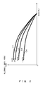
FIG. 2 illustrates a map for correlations between state of charge of a battery and receivable power; -
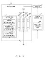
FIG. 3 illustrates the functional block configuration of limiting a vehicle speed during evacuation running in accordance with the invention; and -
FIG. 4 illustrates an exemplary configuration of a battery pack of a vehicle. - When a certain battery cell within a battery block falls into some abnormal state in a vehicle that runs using a motor driven by a battery pack of parallely connected battery blocks, evacuation running is performed by separating the battery block. In this case, however, the decrease in the number of battery blocks leads to a remarkable decrease in the number of battery cells of the entirety of the battery pack, thereby decreasing receivable regenerative electric power, i.e., electric power such that the battery cells of the battery pack are not overcharged by a regenerative current generated by the motor when the vehicle is braked. Accordingly, the present invention prevents battery cells from being overcharged by limiting the speed of the vehicle during evacuation running to the extent that only receivable regenerative electric power is generated.
-
FIG. 1 illustrates the flow of limiting a vehicle speed during evacuation running in accordance with the invention. As depicted inFIG. 1 , a battery electric control unit (ECU) determines whether the current running state of a vehicle is evacuation running in which the vehicle runs under a condition in which some of the battery blocks are separated (step S1). In the case of evacuation running (YES in step S1), the battery electric control unit (ECU) notifies the driver of the vehicle of the fact that the vehicle is performing evacuation running, and calculates receivable regenerative electric power for the number of battery blocks that has been decreased due to the separation (step S2). - The battery electric control unit (ECU) converts the calculated receivable regenerative electric power into kinetic energy, and calculates a vehicle speed that does not exceed the kinetic energy as a limit speed (step S3). The battery electric control unit (ECU) reports the limit speed to a running-control electric control unit (ECU). The running-control electric control unit (ECU) imposes a speed limit on the vehicle in accordance with the limit speed (step S4).
- When it is determined in step S1 described above that the vehicle is not performing evacuation running (NO), the battery electric control unit (ECU) and the running-control electric control unit (ECU) perform ordinary processes (step S5).
- Instead of performing steps S2-3 of the flow, a map indicating relationships between the number of battery blocks and limit speeds may be stored in advance, and the map may be referred to so as to calculate a limit speed from a decreased number of battery blocks.
- The following will describe a method of calculating regenerative electric power that a battery is capable of receiving. Power that a battery is capable of receiving (allowable input power) depends on the temperature of the battery and a state of charge (SOC) that is the ratio of the remaining capacity of the battery relative to the full charge capacity thereof.
FIG. 2 depicts, for each different temperature, a correlation between state of charge of a battery and power that the battery is capable of receiving (allowable input power). - In
FIG. 2 , curves C1, C2, C3, and C4 represent exemplary correlations between the state of charge (SOC) of the battery and power that the battery is capable of receiving (allowable input power) when a battery temperature is 40 degrees C, 25 degrees C, -10 degrees C, and -20 degrees C, respectively. - A map as depicted in
FIG. 2 indicating, for each different temperature, a correlation between a state of charge (SOC) and receivable power (allowable input power) is prepared in advance and stored in a battery electric control unit (ECU). The battery electric control unit (ECU) measures the state of charge (SOC) and temperature of each battery block or battery cell within a battery pack, and refers to the map with reference to the measured state of charge (SOC) and temperature so as to calculate receivable regenerative electric power for the entirety of the battery pack. - When some of parallely connected battery blocks within the battery pack are separated, the receivable regenerative electric power for the entirety of the battery pack is multiplied by {(total number of battery blocks - number of separated battery blocks) ÷ total number of battery blocks}, so as to calculate regenerative electric power that a decreased number of battery blocks remaining after the separation (the batter blocks other than the separated battery blocks) is capable of receiving.
- The following will describe a method of calculating a limit speed of a vehicle from receivable regenerative electric power. Regenerative electric power generated per unit time depends on the power generation capacity of a motor (generator) of a vehicle and the speed thereof. Accordingly, in accordance with the power generation capacity of the motor (generator) and an equation of motion of vehicle speed, receivable regenerative electric power is converted into kinetic energy, and a vehicle speed that does not exceed the kinetic energy is calculated as a limit speed. The calculation may be performed by either of the battery electric control unit (ECU) or the running-control electric control unit (ECU).
-
FIG. 3 illustrates the functional block configuration of a vehicle whose speed is limited during evacuation running in accordance with the invention. As depicted inFIG. 3 , a battery electric control unit (ECU) 1 includes a running determiningunit 31, a regenerative-electric-power calculatingunit 32, and a limitspeed calculating unit 33. A running-control electric control unit (ECU) 2 includes a speedlimit imposing unit 34. - The running determining
unit 31 determines whether the current running state of a vehicle is evacuation running in which the vehicle runs under a condition in which some of the battery blocks are separated. The regenerative-electric-power calculating unit 32 calculates receivable regenerative electric power that a decreased number of battery blocks remaining after some of the battery blocks are separated during evacuation running are capable of receiving such that the remaining battery blocks are not overcharged. - The limit
speed calculating unit 33 converts the calculated receivable regenerative electric power into kinetic energy, calculates a vehicle speed that does not exceed the kinetic energy as a limit speed, and reports the limit speed to the speedlimit imposing unit 34. The speedlimit imposing unit 34 controls theinverter 3 so as to control the vehicle speed in accordance with the reported limit speed. - The limitation of regenerative electric power is necessary during evacuation running performed when an abnormality occurs in a battery due to, for example, overcharge or over-discharge of the battery, evacuation running performed when a communication abnormality associated with the battery electric control unit (ECU) occurs, evacuation running performed when an abnormality occurs in a battery control system, including various sensors within the battery pack, and the like.
- Embodiments of the present invention have been described, but the invention is not limited to the embodiments described above. Various configurations or embodiments may be used without departing from the gist of the invention. For example, although
FIG. 3 depicts an embodiment in which the limitspeed calculating unit 33 is provided within the battery electric control unit (ECU) 1, the limitspeed calculating unit 33 may be provided within the running-control electric control unit (ECU) 2. - Receivable regenerative electric power is not limited to an amount of power that does not overcharge a battery block used for evacuation running of a vehicle, but may be an amount of power such that an abnormality does not occur in a circuit (e.g., monitoring circuit) provided at each battery block or an amount of power such that a fuse blowout is prevented from occurring. This may prevent a large current from flowing through the battery blocks, so that a circuit abnormality and a fuse blowout can be prevented from occurring.
-
- 1
- Battery electric control unit (ECU)
- 2
- Running-control electric control unit (ECU)
- 3
- Inverter
- 10
- Battery pack
- 11
- Battery block
- 12
- Battery block
- 13
- Battery block
- 21
- Switch
- 22
- Switch
- 23
- Switch
- 31
- Running determining unit
- 32
- Regenerative-electric-power calculating unit
- 33
- Limit speed calculating unit
- 34
- Speed limit imposing unit
Claims (4)
- A method of limiting a vehicle speed during evacuation running, the method comprising:a regenerative-electric-power calculating step of calculating, in causing a vehicle to run under a condition in which some of a plurality of parallely connected battery blocks are separated, regenerative electric power that a decreased number of battery blocks remaining after the separation is capable of receiving;a limit speed calculating step of calculating a limit speed of the vehicle according to the receivable regenerative electric power calculated in the regenerative-electric-power calculating step, in a manner such that regenerative electric power generated when the vehicle is braked does not exceed the receivable regenerative electric power; anda vehicle speed limiting step of limiting the speed of the vehicle to the limit speed calculated in the limit speed calculating step or to a speed lower than the limit speed.
- The method of limiting the vehicle speed during evacuation running according to claim 1, wherein
the regenerative-electric-power calculating step includes storing in advance, for each different temperature, a map indicating a correlation between the receivable power and a state of charge of the battery blocks, and referring to the map according to a state of charge and temperature of a battery block used for running of the vehicle so as to calculate regenerative electric power that the battery block used for running of the vehicle is capable of receiving. - The method of limiting the vehicle speed during evacuation running according to claim 1 or 2, wherein
the limit speed calculating step includes converting the receivable regenerative electric power into kinetic energy of the vehicle, and calculating, as a vehicle limit speed, a vehicle speed that does not exceed the kinetic energy. - A vehicle that runs using a motor driven by a plurality of parallely connected battery blocks, the vehicle comprising:a running determining unit to determine whether the vehicle is performing evacuation running in which the vehicle runs under a condition in which some of the plurality of parallely connected battery blocks are separated;a regenerative-electric-power calculating unit to calculate regenerative electric power that a decreased number of battery blocks remaining after the separation in the evacuation running is capable of receiving;a limit speed calculating unit to calculate a limit speed of the vehicle in a manner such that regenerative electric power generated when the vehicle is braked becomes the receivable regenerative electric power or power less than the receivable regenerative electric power; anda speed limit imposing unit to control an inverter for driving the motor that causes the vehicle to run, in a manner such that the speed of the vehicle becomes the limit speed calculated by the limit speed calculating unit or a speed that is lower than the limit speed.
Applications Claiming Priority (2)
| Application Number | Priority Date | Filing Date | Title |
|---|---|---|---|
| JP2013013238A JP2014147168A (en) | 2013-01-28 | 2013-01-28 | Vehicle speed limiting method during evacuation and vehicle |
| PCT/JP2013/073955 WO2014115365A1 (en) | 2013-01-28 | 2013-09-05 | Method for limiting vehicle speed at time of evasive travel, and vehicle |
Publications (1)
| Publication Number | Publication Date |
|---|---|
| EP2949502A1 true EP2949502A1 (en) | 2015-12-02 |
Family
ID=51227173
Family Applications (1)
| Application Number | Title | Priority Date | Filing Date |
|---|---|---|---|
| EP13872800.1A Withdrawn EP2949502A1 (en) | 2013-01-28 | 2013-09-05 | Method for limiting vehicle speed at time of evasive travel, and vehicle |
Country Status (5)
| Country | Link |
|---|---|
| US (1) | US20150321562A1 (en) |
| EP (1) | EP2949502A1 (en) |
| JP (1) | JP2014147168A (en) |
| CN (1) | CN104936818A (en) |
| WO (1) | WO2014115365A1 (en) |
Families Citing this family (8)
| Publication number | Priority date | Publication date | Assignee | Title |
|---|---|---|---|---|
| JP6325431B2 (en) * | 2014-12-22 | 2018-05-16 | 住友ナコ フォ−クリフト株式会社 | Vehicle for cargo handling work |
| JP6547410B2 (en) * | 2015-05-19 | 2019-07-24 | 日産自動車株式会社 | Vehicle driving force control device |
| JP6555114B2 (en) * | 2015-12-17 | 2019-08-07 | 株式会社豊田自動織機 | Battery pack |
| US10322688B2 (en) * | 2016-12-30 | 2019-06-18 | Textron Innovations Inc. | Controlling electrical access to a lithium battery on a utility vehicle |
| JP7548024B2 (en) * | 2021-01-13 | 2024-09-10 | トヨタ自動車株式会社 | Information processing device and program |
| JP2023141950A (en) * | 2022-03-24 | 2023-10-05 | いすゞ自動車株式会社 | battery management device |
| US11661060B1 (en) * | 2022-07-06 | 2023-05-30 | Hyster-Yale Group, Inc. | Direction-of-travel-based inhibition of speed control based on truck-to-truck proximity detection |
| JP2024075854A (en) * | 2022-11-24 | 2024-06-05 | トヨタ自動車株式会社 | Electric vehicle control device |
Family Cites Families (15)
| Publication number | Priority date | Publication date | Assignee | Title |
|---|---|---|---|---|
| JP4096261B2 (en) * | 2003-12-05 | 2008-06-04 | 富士電機システムズ株式会社 | Battery protection system |
| JP2006312352A (en) * | 2005-05-06 | 2006-11-16 | Toyota Motor Corp | Control device for drive system |
| JP4745879B2 (en) * | 2006-04-06 | 2011-08-10 | 日立ビークルエナジー株式会社 | Hybrid vehicle control system, hybrid vehicle control method, and vehicle storage battery control system |
| JP4265629B2 (en) * | 2006-08-01 | 2009-05-20 | トヨタ自動車株式会社 | Secondary battery charge / discharge control device and hybrid vehicle equipped with the same |
| JP4803810B2 (en) * | 2006-08-25 | 2011-10-26 | 本田技研工業株式会社 | Small electric vehicle |
| JP5456263B2 (en) | 2007-05-02 | 2014-03-26 | 日産自動車株式会社 | Drive control apparatus for hybrid vehicle |
| JP5374934B2 (en) * | 2008-06-20 | 2013-12-25 | トヨタ自動車株式会社 | Travel control device |
| JP2010093876A (en) * | 2008-10-03 | 2010-04-22 | Fujitsu Ltd | Battery unit, battery system, electronic device, charging control method of battery, and discharging control method of battery |
| EP2353920B1 (en) * | 2008-10-31 | 2019-01-23 | Toyota Jidosha Kabushiki Kaisha | Electrically driven vehicle and electrically driven vehicle control method |
| JP2010220323A (en) * | 2009-03-13 | 2010-09-30 | Toshiba Corp | Secondary battery pack and motor control system |
| JP2010233367A (en) * | 2009-03-27 | 2010-10-14 | Fuji Electric Systems Co Ltd | Electric propulsion system control system |
| KR20110134751A (en) * | 2010-06-09 | 2011-12-15 | 삼성에스디아이 주식회사 | Battery pack and its control method |
| WO2012004842A1 (en) * | 2010-07-05 | 2012-01-12 | パイオニア株式会社 | Driving maneuver assistance device and driving maneuver assistance method |
| JP2012050158A (en) * | 2010-08-24 | 2012-03-08 | Suzuki Motor Corp | Electric vehicle |
| WO2014126563A1 (en) * | 2013-02-14 | 2014-08-21 | Otis Elevator Company | Elevator car speed control in a battery powered elevator system |
-
2013
- 2013-01-28 JP JP2013013238A patent/JP2014147168A/en active Pending
- 2013-09-05 EP EP13872800.1A patent/EP2949502A1/en not_active Withdrawn
- 2013-09-05 US US14/761,205 patent/US20150321562A1/en not_active Abandoned
- 2013-09-05 CN CN201380070940.1A patent/CN104936818A/en active Pending
- 2013-09-05 WO PCT/JP2013/073955 patent/WO2014115365A1/en not_active Ceased
Also Published As
| Publication number | Publication date |
|---|---|
| JP2014147168A (en) | 2014-08-14 |
| US20150321562A1 (en) | 2015-11-12 |
| CN104936818A (en) | 2015-09-23 |
| WO2014115365A1 (en) | 2014-07-31 |
Similar Documents
| Publication | Publication Date | Title |
|---|---|---|
| US20150321562A1 (en) | Method of limiting vehicle speed during evacuation running, and vehicle | |
| US10454283B2 (en) | Battery system monitoring apparatus and electric storage device including the same | |
| EP2857854B1 (en) | Cell control device | |
| JP5753764B2 (en) | Battery system monitoring device and power storage device including the same | |
| EP2988144B1 (en) | Battery system monitoring device | |
| US9680320B2 (en) | Battery control apparatus | |
| EP3468830B1 (en) | A method and a device for controlling the operation of an energy storage system in a vehicle | |
| EP2343558A2 (en) | Battery system and method for detecting internal short circuit in battery system | |
| TW202234785A (en) | Systems and methods for fail-safe battery protection independent from battery management system | |
| US20130229152A1 (en) | Power supply stack replacement method, control device, and storage medium storing control program | |
| JP2011135657A (en) | Battery system and vehicle with the same, and method for detecting current limit state of the battery system | |
| EP3349320B1 (en) | Storage battery control device | |
| JP6251136B2 (en) | Battery system monitoring device and power storage device including the same | |
| US20140368206A1 (en) | Battery control device | |
| CN112512855B (en) | System for driving an energy accumulator and method for charging | |
| JP2005269752A (en) | Hybrid car power supply | |
| JP2011069720A (en) | Power supply device for vehicle and vehicle to which power supply device is mounted | |
| JP2014240807A (en) | Battery pack abnormality determination apparatus | |
| US9634500B2 (en) | Storage battery system | |
| US9859591B2 (en) | Method for operating intrinsically safe battery cells | |
| JP2005117765A (en) | Battery pack protection control device and battery pack protection control method | |
| JP2016086468A (en) | Relay control device | |
| CN105871037B (en) | Battery management system and method | |
| JP2011072096A (en) | Power supply device for vehicle and vehicle mounted with this power supply device | |
| CN105337364A (en) | Power management system for electric ship and management method thereof |
Legal Events
| Date | Code | Title | Description |
|---|---|---|---|
| PUAI | Public reference made under article 153(3) epc to a published international application that has entered the european phase |
Free format text: ORIGINAL CODE: 0009012 |
|
| 17P | Request for examination filed |
Effective date: 20150720 |
|
| AK | Designated contracting states |
Kind code of ref document: A1 Designated state(s): AL AT BE BG CH CY CZ DE DK EE ES FI FR GB GR HR HU IE IS IT LI LT LU LV MC MK MT NL NO PL PT RO RS SE SI SK SM TR |
|
| AX | Request for extension of the european patent |
Extension state: BA ME |
|
| DAX | Request for extension of the european patent (deleted) | ||
| STAA | Information on the status of an ep patent application or granted ep patent |
Free format text: STATUS: THE APPLICATION HAS BEEN WITHDRAWN |
|
| 18W | Application withdrawn |
Effective date: 20160901 |