EP2949495A1 - Hybrid four-wheel-drive vehicle - Google Patents
Hybrid four-wheel-drive vehicle Download PDFInfo
- Publication number
- EP2949495A1 EP2949495A1 EP15736368.0A EP15736368A EP2949495A1 EP 2949495 A1 EP2949495 A1 EP 2949495A1 EP 15736368 A EP15736368 A EP 15736368A EP 2949495 A1 EP2949495 A1 EP 2949495A1
- Authority
- EP
- European Patent Office
- Prior art keywords
- shaft
- input shaft
- transfer case
- torque transfer
- driving power
- Prior art date
- Legal status (The legal status is an assumption and is not a legal conclusion. Google has not performed a legal analysis and makes no representation as to the accuracy of the status listed.)
- Granted
Links
Images


Classifications
-
- B—PERFORMING OPERATIONS; TRANSPORTING
- B60—VEHICLES IN GENERAL
- B60K—ARRANGEMENT OR MOUNTING OF PROPULSION UNITS OR OF TRANSMISSIONS IN VEHICLES; ARRANGEMENT OR MOUNTING OF PLURAL DIVERSE PRIME-MOVERS IN VEHICLES; AUXILIARY DRIVES FOR VEHICLES; INSTRUMENTATION OR DASHBOARDS FOR VEHICLES; ARRANGEMENTS IN CONNECTION WITH COOLING, AIR INTAKE, GAS EXHAUST OR FUEL SUPPLY OF PROPULSION UNITS IN VEHICLES
- B60K6/00—Arrangement or mounting of plural diverse prime-movers for mutual or common propulsion, e.g. hybrid propulsion systems comprising electric motors and internal combustion engines
- B60K6/20—Arrangement or mounting of plural diverse prime-movers for mutual or common propulsion, e.g. hybrid propulsion systems comprising electric motors and internal combustion engines the prime-movers consisting of electric motors and internal combustion engines, e.g. HEVs
- B60K6/42—Arrangement or mounting of plural diverse prime-movers for mutual or common propulsion, e.g. hybrid propulsion systems comprising electric motors and internal combustion engines the prime-movers consisting of electric motors and internal combustion engines, e.g. HEVs characterised by the architecture of the hybrid electric vehicle
- B60K6/48—Parallel type
-
- B—PERFORMING OPERATIONS; TRANSPORTING
- B60—VEHICLES IN GENERAL
- B60K—ARRANGEMENT OR MOUNTING OF PROPULSION UNITS OR OF TRANSMISSIONS IN VEHICLES; ARRANGEMENT OR MOUNTING OF PLURAL DIVERSE PRIME-MOVERS IN VEHICLES; AUXILIARY DRIVES FOR VEHICLES; INSTRUMENTATION OR DASHBOARDS FOR VEHICLES; ARRANGEMENTS IN CONNECTION WITH COOLING, AIR INTAKE, GAS EXHAUST OR FUEL SUPPLY OF PROPULSION UNITS IN VEHICLES
- B60K6/00—Arrangement or mounting of plural diverse prime-movers for mutual or common propulsion, e.g. hybrid propulsion systems comprising electric motors and internal combustion engines
- B60K6/20—Arrangement or mounting of plural diverse prime-movers for mutual or common propulsion, e.g. hybrid propulsion systems comprising electric motors and internal combustion engines the prime-movers consisting of electric motors and internal combustion engines, e.g. HEVs
- B60K6/50—Architecture of the driveline characterised by arrangement or kind of transmission units
- B60K6/52—Driving a plurality of drive axles, e.g. four-wheel drive
-
- B—PERFORMING OPERATIONS; TRANSPORTING
- B60—VEHICLES IN GENERAL
- B60K—ARRANGEMENT OR MOUNTING OF PROPULSION UNITS OR OF TRANSMISSIONS IN VEHICLES; ARRANGEMENT OR MOUNTING OF PLURAL DIVERSE PRIME-MOVERS IN VEHICLES; AUXILIARY DRIVES FOR VEHICLES; INSTRUMENTATION OR DASHBOARDS FOR VEHICLES; ARRANGEMENTS IN CONNECTION WITH COOLING, AIR INTAKE, GAS EXHAUST OR FUEL SUPPLY OF PROPULSION UNITS IN VEHICLES
- B60K17/00—Arrangement or mounting of transmissions in vehicles
- B60K17/34—Arrangement or mounting of transmissions in vehicles for driving both front and rear wheels, e.g. four wheel drive vehicles
- B60K17/344—Arrangement or mounting of transmissions in vehicles for driving both front and rear wheels, e.g. four wheel drive vehicles having a transfer gear
-
- B—PERFORMING OPERATIONS; TRANSPORTING
- B60—VEHICLES IN GENERAL
- B60K—ARRANGEMENT OR MOUNTING OF PROPULSION UNITS OR OF TRANSMISSIONS IN VEHICLES; ARRANGEMENT OR MOUNTING OF PLURAL DIVERSE PRIME-MOVERS IN VEHICLES; AUXILIARY DRIVES FOR VEHICLES; INSTRUMENTATION OR DASHBOARDS FOR VEHICLES; ARRANGEMENTS IN CONNECTION WITH COOLING, AIR INTAKE, GAS EXHAUST OR FUEL SUPPLY OF PROPULSION UNITS IN VEHICLES
- B60K6/00—Arrangement or mounting of plural diverse prime-movers for mutual or common propulsion, e.g. hybrid propulsion systems comprising electric motors and internal combustion engines
- B60K6/20—Arrangement or mounting of plural diverse prime-movers for mutual or common propulsion, e.g. hybrid propulsion systems comprising electric motors and internal combustion engines the prime-movers consisting of electric motors and internal combustion engines, e.g. HEVs
- B60K6/42—Arrangement or mounting of plural diverse prime-movers for mutual or common propulsion, e.g. hybrid propulsion systems comprising electric motors and internal combustion engines the prime-movers consisting of electric motors and internal combustion engines, e.g. HEVs characterised by the architecture of the hybrid electric vehicle
- B60K6/48—Parallel type
- B60K2006/4808—Electric machine connected or connectable to gearbox output shaft
-
- Y—GENERAL TAGGING OF NEW TECHNOLOGICAL DEVELOPMENTS; GENERAL TAGGING OF CROSS-SECTIONAL TECHNOLOGIES SPANNING OVER SEVERAL SECTIONS OF THE IPC; TECHNICAL SUBJECTS COVERED BY FORMER USPC CROSS-REFERENCE ART COLLECTIONS [XRACs] AND DIGESTS
- Y02—TECHNOLOGIES OR APPLICATIONS FOR MITIGATION OR ADAPTATION AGAINST CLIMATE CHANGE
- Y02T—CLIMATE CHANGE MITIGATION TECHNOLOGIES RELATED TO TRANSPORTATION
- Y02T10/00—Road transport of goods or passengers
- Y02T10/60—Other road transportation technologies with climate change mitigation effect
- Y02T10/62—Hybrid vehicles
Definitions
- the present invention relates to a hybrid four-wheel drive vehicle and, more particularly, to a hybrid four-wheel drive vehicle fabricated by installing a motor generator to a four-wheel drive vehicle derived from a rear wheel drive vehicle.
- a conventional hybrid four-wheel drive vehicle is known in which easiness of mounting a motor generator to the vehicle is ensured by installing the motor generator inside a transfer housing of a torque transfer case, see JP Patent No. 3646705 (Patent Literature 1).
- Patent Literature 1 JP Patent No. 3646705
- the present invention aims to provide a hybrid four-wheel drive vehicle which may be fabricated from an existing non-hybrid four-wheel drive vehicle without any drastic remodeling and which may possess an improved travelling performance.
- a hybrid four-wheel drive vehicle including an engine, a transmission coupled to a rear end of the engine, a torque transfer case coupled to the transmission from behind through a first propeller shaft and located below a floor panel, a second propeller shaft for transmission of driving power from the torque transfer case to rear traction wheels, a third propeller shaft for transmission of driving power from the torque transfer case to front traction wheels, and a rotary electric machine which can transmit driving power to the rear traction wheels and the front traction wheels, the second propeller shaft and the third propeller shaft being disposed on an axis which is offset in a transverse direction of the vehicle from an axis of the first propeller shaft, wherein, with respect to a rear outer wall of the torque transfer case, the rotary electric machine is coupled to the torque transfer case from that side of the rear outer wall which is located behind, as viewed from above the vehicle, the first propeller shaft.
- the torque transfer case comprises a first input shaft coupled to the first propeller shaft, a second input shaft coupled to the rotary electric machine, and an output shaft, which may be given driving power transmitted from the first and second input shaft through a gear train, connectable to the second propeller shaft and the third propeller shaft, and that the second input shaft is located below the first input shaft when viewing the torque transfer case in an axial direction along an axis of the first input shaft, an axis of the second input shaft and an axis of the output shaft.
- the torque transfer case comprises a counter shaft, which may be given driving power transmitted from the first and second input shaft through an input gear train working as the gear train, and a shift mechanism, located between the counter shaft and the output shaft, configured to enable a shift between a driving power delivery mode in which driving power is transmitted from the counter shaft to the output shaft through either a first gear train or a second gear train, which work as the gear train, and a neutral mode in which driving power is not transmitted from the counter shaft to the output shaft, and that, when the shift mechanism is caused to shift into the neutral mode, the rotary electric machine is driven to generate electricity by driving power produced by the engine transmitted to the second input shaft from the first input shaft through the counter shaft.
- a rotary electric machine is coupled to a torque transfer case, which is located below a floor panel, from a side of its rear outer wall, so that, without remodeling a floor panel of an existing non-hybrid four-wheel drive vehicle, a relatively large, in outer diameter, high-output rotary electric machine may be installed at a low position below the floor panel.
- the rotary electric machine is coupled to the torque transfer case after passing through the rear outer wall from a location behind, as viewed from above the vehicle, the first propeller shaft, so that the rotary electric machine may be coupled to the torque transfer case without changing the locations of the first propeller shaft, second propeller shaft and third propeller shaft.
- the rotary electric machine is not provided inside the torque transfer case but coupled to the torque transfer case from the side of the rear outer wall, a power supply cable may be connected to the rotary electric machine without drastically remodeling a transfer housing of the torque transfer case.
- a hybrid four-wheel drive vehicle may be fabricated from an existing non-hybrid four-wheel drive vehicle equipped with a torque transfer case without any drastic modification, and travelling performance of the vehicle may be improved.
- the second input shaft coupled to the rotary electric machine is located below the first input shaft coupled to the first propeller shaft, the distance to the vehicle body (floor panel) from the second input shaft may be increased.
- a large, in outer diameter, rotary electric machine may be installed to the vehicle.
- the rotary electric machine can generate electric power by being driven by driving power produced by the engine which is transmitted from the first input shaft to the second input shaft through the counter shaft.
- FIGS. 1 to 5 are views depicting the embodiment of hybrid four-wheel drive vehicle according to the present invention.
- a hybrid four-wheel drive vehicle 10 includes, on a vehicle body 30, an engine 11 and a motor generator 50, as power sources, a pair of rear traction wheels 22R, 22L, and a pair of front traction wheels 20R, 20L. Moreover, hybrid four-wheel drive vehicle 10 includes, on vehicle body 30, a driveline 40 which transmits power from engine 11 and motor generator 50 to only rear traction wheels 22R, 22L or to all of rear traction wheels 22R, 22L and front traction wheels 20R, 20L.
- Hybrid four-wheel drive vehicle 10 is configured to travel by transmitting output power of engine 11 and motor generator 50 to rear traction wheels 22R, 22L and front traction wheels 20R, 20L through driveline 40.
- Vehicle body 30 includes a dash panel 31 and a floor panel of a front floor panel 32, a floor tunnel 33, a vertical wall section 34 and a rear floor panel 35.
- Dash panel 31 extends in almost vertical direction between an engine compartment in which engine 11 is placed and a passenger compartment to serve as a partition between the engine compartment and the passenger compartment.
- Front floor panel 32 constitutes that portion of the floor which extends forward from the middle of vehicle body 30, while rear floor panel 35 constitutes that portion of the floor which extends backward from the middle of vehicle body 30.
- Vertical wall section 34 is provided at the rear end of front floor panel 32 and extends in an upward direction, and this vertical wall section 34 has an upper end, to which rear floor panel 35 is continuous. This makes rear floor panel 35 higher, in a vertical direction of the vehicle, than front floor panel 32.
- vehicle body 30 includes various kinds of support members (a sub-frame and the like) which support engine 11 and transmission 12.
- Engine 11 is an internal combustion engine which operates on combustion of fuel, and it is longitudinally mounted, in a backward tilting position, at the front part of vehicle body 30.
- Driveline 40 includes transmission 12 as a gearbox, a first propeller shaft 13, a torque transfer case 60, a second propeller shaft 15 and a third propeller shaft 17. Moreover, driveline 40 includes: a rear differential 16; a front differential 18; front traction wheels 20L, 20R; and rear traction wheels 22R, 22L.
- Transmission 12 is coupled to the rear end of engine 11 and configured to convert, using gears, not shown, input power fed by engine 11 to provide an output. Transmission 12 is located, in a backward tilting position, below floor tunnel 33. Transmission 12 may be constituted by an automatic transmission or a manual transmission.
- Torque transfer case 60 is coupled to transmission 12 from behind through first propeller shaft 13. Torque transfer case 60 is located below front floor panel 32 and almost at the middle with respect to the forward and rear direction of the vehicle. First propeller shaft 13 is coupled to torque transfer case 60 after passing through a front wall surface which is situated on the left-hand side with respect to a transverse direction of the vehicle and on the upper side with respect to a vertical direction of the vehicle.
- Second propeller shaft 15 for transmission of power to rear traction wheels 22R, 22L is coupled to torque transfer case 60 after passing through a rear outer wall which is situated on the right-hand side with respect to the transverse direction of the vehicle and on the lower side with respect to the vertical direction of the vehicle.
- third propeller shaft 17 for transmission of power to front traction wheels 20R, 20L is coupled to torque transfer case 60 after passing through a front outer wall which is situated on the right-hand side with respect to the transverse direction of the vehicle and on the lower side with respect to the vertical direction of the vehicle.
- second propeller shaft 15 and third propeller shaft 17 are disposed on an axis which is offset in the transverse direction of the vehicle from an axis of first propeller shaft 13.
- a motor generator 50 is coupled to torque transfer case 60 after passing through a rear outer wall which is situated on the left-hand side with respect to the transverse direction of the vehicle and on the lower side with respect to the vertical direction of the vehicle.
- motor generator 50 is coupled to torque transfer case 60 from that side of the rear outer wall which is located behind, as viewed from above the vehicle, first propeller shaft 13.
- Motor generator 50 when serving as a traction motor, can produce driving power for propelling by using electricity from a battery, not shown, to provide the produced driving power to torque transfer case 60 for transmission of driving power only to rear traction wheels 22R, 22L or all of rear traction wheels 22R, 22L and front traction wheels 20R, 20L.
- motor generator 50 when serving as a generator, can generate electricity by being rotated by driving power fed from torque transfer case 60.
- Motor generator 50 for the present embodiment constitutes a rotary electric machine in the present invention.
- a rear differential 16 at a rear end of second propeller shaft 15, and this rear differential 16 is configured to distribute driving power from second propeller shaft 15 to left and right rear traction wheels 22R, 22L while allowing some difference in rotational speed between the left and right rear traction wheels 22R, 22L.
- a front differential 18 at a front end of third propeller shaft 17, and this front differential 18 is configured to distribute driving power from third propeller shaft 17 to left and right front traction wheels 20R, 20L while allowing some difference in rotational speed between the left and right front traction wheels 20R, 20L.
- torque transfer case 60 includes a transfer housing 61, and a powertrain input shaft 62, which works as a first input shaft, is rotatably supported on a left-side front end portion within this transfer housing 61.
- powertrain input shaft 62 is coupled to the rear end of first propeller shaft 13 through a joint 13a. Moreover, a drive gear 63 is fixedly coupled to powertrain input shaft 62.
- a motor generator input shaft 69 which works as a second input shaft, is rotatably supported on a left-side rear end portion within this transfer housing 61. At the rear end, motor generator input shaft 69 is coupled to motor generator 50.
- a drive gear 70 is fixedly coupled to motor generator input shaft 69.
- a counter shaft 64 is rotatably supported about its axis on almost the middle portion in the transverse direction of the vehicle within transfer housing 61. Driven gears 65, 68 are fixedly coupled to counter shaft 64.
- Driven gears 65 and 68 engage drive gear 63 on powertrain input shaft 62 and drive gear 70 on motor generator input shaft 69, respectively.
- Drive gears 63, 70 and driven gears 65, 68 constitute an input gear train.
- drive gears 66, 67 are fixedly coupled to counter shaft 64.
- An output shaft 71 is rotatably supported about its axis on the right-side portion within transfer housing 61.
- Driven gears 72, 73 are provided around output shaft 71, and these driven gears 72 and 73 engage drive gears 66 and 67, respectively.
- Driven gear 72 and drive gear 66 constitute a first gear train 75 configured to provide a high speed stage
- driven gear 73 and drive gear 67 constitute a second gear train 76 configured to provide a low speed stage.
- output shaft 71 is coupled to the front end of second propeller shaft 15 through a joint 15a, and at the front end, output shaft 71 is coupled to the rear end of third propeller shaft 17 through a joint 17a.
- 2WD-4WD switching mechanism 77 On the side in which the front end of output shaft 71 is, there is provided a 2WD-4WD switching mechanism 77.
- 2WD-4WD switching mechanism 77 is configured to engage its friction engagement element when it is operated by a vehicle driver to switch to 4WD position.
- 2WD-4WD switching mechanism 77 is configured to disengage its friction engagement element when it is operated by a vehicle driver to switch to 2WD position.
- torque of output shaft 71 is delivered to only the second propeller shaft 15, and the vehicle becomes operable in 2WD mode.
- a sleeve 74 is provided on output shaft 71 and sleeve 74 is configured to move on output shaft 71 in forward and backward direction by switching operation by a vehicle driver.
- sleeve 74 is operated to switch to a high speed position after being moved on output shaft 71 in forward direction, driven gear 72 is brought into rotation with output shaft 71 thereby to provide high speed stage in cooperation with drive gear 66.
- driven gear 73 is brought into rotation with output shaft 71 thereby to provide low speed stage in cooperation with drive gear 67.
- driven gears 72, 73 are brought into relative rotation to output shaft 71 thereby to interrupt power delivery between output shaft 71 and counter shaft 64.
- driving power may be delivered from powertrain input shaft 62 and motor generator input shaft 69 to output shaft 71 through a gear train including drive gears 63, 70, driven gears 65, 68, drive gears 66, 67 and driven gears 72, 76.
- sleeve 74, first gear train 75 and second gear train 76 constitute a shift mechanism 78 which is configured to enable a shift between the driving power delivery mode (that is, a mode in which the high speed stage or low speed stage is provided) in which driving power is transmitted from counter shaft 64 to output shaft 71 through either first gear train 75 or second gear train 76, and the neutral mode in which driving power is not transmitted from counter shaft 64 to output shaft 71.
- the driving power delivery mode that is, a mode in which the high speed stage or low speed stage is provided
- motor generator 50 when shift mechanism 78 is caused to shift into the neutral mode, motor generator 50 is driven to generate electricity by driving power produced by engine 11 transmitted to motor generator input shaft 69 from powertrain input shaft 62 through counter shaft 64.
- motor generator input shaft 69 is located below powertrain input shaft 62 when viewing, in FIG. 4 , torque transfer case 60 from the side of vehicle and viewing, in FIG. 5 , torque transfer case 60 in an axial direction (that is, a direction of an axis) along an axis of powertrain input shaft 62, an axis of motor generator input shaft 69 and an axis of output shaft 71.
- a power supply cable 79 is connected to the rear part of motor generator 50 for supply of power from a battery.
- hybrid four-wheel drive vehicle 10 can travel by both driving power produced by engine 11 and driving power produced by motor generator 50.
- motor generator 50 is coupled to torque transfer case 60 from that side of the rear outer wall which is located behind, as viewed from above hybrid four-wheel drive vehicle 10, the first propeller shaft 13.
- motor generator 50 is coupled to the rear outer wall of torque transfer case 60 which is located below front floor panel 32, so that, without remodeling the floor panel of an existing non-hybrid four-wheel drive vehicle, a relatively large, in outer diameter, high-output motor generator may be installed at a low position below the floor panel. This improves travelling performance of hybrid four-wheel drive vehicle 10 by lowering the center of gravity and souping up the hybrid four-wheel drive vehicle by such motor generator 50.
- motor generator 50 is coupled to the rear outer wall of torque transfer case 60 located behind, as viewed from above hybrid four wheel drive vehicle 10, the first propeller shaft 13, so that motor generator 50 may be coupled to torque transfer case 60 without changing the locations of the first propeller shaft 13, second propeller shaft 15 and third propeller shaft 17.
- motor generator 50 is not provided inside torque transfer case 60 but coupled to torque transfer case 60 from the exterior of the rear outer wall, power supply cable 79 may be connected to motor generator 50 without drastically remodeling transfer housing 61.
- hybrid four-wheel drive vehicle 10 may be fabricated from an existing non-hybrid four-wheel drive vehicle equipped with a torque transfer case without any drastic modification, and travelling performance of hybrid four-wheel drive vehicle 10 may be improved.
- motor generator input shaft 69 is located below powertrain input shaft 62 when viewing torque transfer case 60 in an axial direction along an axis of powertrain input shaft 62, an axis of motor generator input shaft 69 and an axis of output shaft 71.
- motor generator input shaft 69 coupled to motor generator 50 is located below powertrain input shaft 62 coupled to the first propeller shaft 13, so that the distance to vehicle body 30, i.e., front floor panel 32 and floor tunnel 33, from motor generator input shaft 69 may be increased.
- motor generator 50 may be installed to hybrid four-wheel drive vehicle 10.
- motor generator 50 when shift mechanism 78 is caused to shift into the neutral mode, motor generator 50 is driven to generate electricity by driving power produced by engine 11 transmitted to motor generator input shaft 69 from powertrain input shaft 62 through counter shaft 64.
- motor generator 50 can generate electric power by being driven by driving power produced by engine 11 which is transmitted from powertrain input shaft 62 to motor generator input shaft 69 through counter shaft 64.
Landscapes
- Engineering & Computer Science (AREA)
- Chemical & Material Sciences (AREA)
- Combustion & Propulsion (AREA)
- Transportation (AREA)
- Mechanical Engineering (AREA)
- Arrangement And Driving Of Transmission Devices (AREA)
- Hybrid Electric Vehicles (AREA)
- Electric Propulsion And Braking For Vehicles (AREA)
Abstract
Description
- The present invention relates to a hybrid four-wheel drive vehicle and, more particularly, to a hybrid four-wheel drive vehicle fabricated by installing a motor generator to a four-wheel drive vehicle derived from a rear wheel drive vehicle.
- In cases when a hybrid four-wheel drive vehicle is fabricated by installing a motor generator to a four-wheel drive vehicle derived from a rear wheel drive vehicle, the motor generator is installed somewhere in its power transmission path.
- A conventional hybrid four-wheel drive vehicle is known in which easiness of mounting a motor generator to the vehicle is ensured by installing the motor generator inside a transfer housing of a torque transfer case, see
JP Patent No. 3646705 - Patent Literature 1:
JP Patent No. 3646705 - However, the conventional practice employed upon fabricating a hybrid four-wheel drive vehicle by installing a motor generator to an existing non-hybrid four-wheel drive vehicle poses a problem that the transfer housing needs to be drastically remodeled to meet a need for installation of the motor generator inside the transfer housing and a need for connection of a power supply cable to the motor generator.
- Moreover, there is another problem that it is difficult to install a motor generator capable of producing a high output torque to improve the travelling performance because the transfer housing limits the size of a motor generator which may be allowed inside and the location where the motor generator may be allowed to operate.
- In view of the above-mentioned problems, the present invention aims to provide a hybrid four-wheel drive vehicle which may be fabricated from an existing non-hybrid four-wheel drive vehicle without any drastic remodeling and which may possess an improved travelling performance.
- In order to achieve the object by solving the problems described above, there is provided, according to a first aspect of the present invention, a hybrid four-wheel drive vehicle including an engine, a transmission coupled to a rear end of the engine, a torque transfer case coupled to the transmission from behind through a first propeller shaft and located below a floor panel, a second propeller shaft for transmission of driving power from the torque transfer case to rear traction wheels, a third propeller shaft for transmission of driving power from the torque transfer case to front traction wheels, and a rotary electric machine which can transmit driving power to the rear traction wheels and the front traction wheels, the second propeller shaft and the third propeller shaft being disposed on an axis which is offset in a transverse direction of the vehicle from an axis of the first propeller shaft, wherein, with respect to a rear outer wall of the torque transfer case, the rotary electric machine is coupled to the torque transfer case from that side of the rear outer wall which is located behind, as viewed from above the vehicle, the first propeller shaft.
- According to a second aspect of the present invention, it is preferable that the torque transfer case comprises a first input shaft coupled to the first propeller shaft, a second input shaft coupled to the rotary electric machine, and an output shaft, which may be given driving power transmitted from the first and second input shaft through a gear train, connectable to the second propeller shaft and the third propeller shaft, and that the second input shaft is located below the first input shaft when viewing the torque transfer case in an axial direction along an axis of the first input shaft, an axis of the second input shaft and an axis of the output shaft.
- According to a third aspect of the present invention, it is preferable that the torque transfer case comprises a counter shaft, which may be given driving power transmitted from the first and second input shaft through an input gear train working as the gear train, and a shift mechanism, located between the counter shaft and the output shaft, configured to enable a shift between a driving power delivery mode in which driving power is transmitted from the counter shaft to the output shaft through either a first gear train or a second gear train, which work as the gear train, and a neutral mode in which driving power is not transmitted from the counter shaft to the output shaft, and that, when the shift mechanism is caused to shift into the neutral mode, the rotary electric machine is driven to generate electricity by driving power produced by the engine transmitted to the second input shaft from the first input shaft through the counter shaft.
- According to the first aspect of the present invention, a rotary electric machine is coupled to a torque transfer case, which is located below a floor panel, from a side of its rear outer wall, so that, without remodeling a floor panel of an existing non-hybrid four-wheel drive vehicle, a relatively large, in outer diameter, high-output rotary electric machine may be installed at a low position below the floor panel. This improves travelling performance of a hybrid four-wheel drive vehicle by lowering the center of gravity and souping up the hybrid four-wheel drive vehicle by such rotary electric machine.
- Moreover, the rotary electric machine is coupled to the torque transfer case after passing through the rear outer wall from a location behind, as viewed from above the vehicle, the first propeller shaft, so that the rotary electric machine may be coupled to the torque transfer case without changing the locations of the first propeller shaft, second propeller shaft and third propeller shaft.
- Furthermore, the rotary electric machine is not provided inside the torque transfer case but coupled to the torque transfer case from the side of the rear outer wall, a power supply cable may be connected to the rotary electric machine without drastically remodeling a transfer housing of the torque transfer case.
- As a result, a hybrid four-wheel drive vehicle may be fabricated from an existing non-hybrid four-wheel drive vehicle equipped with a torque transfer case without any drastic modification, and travelling performance of the vehicle may be improved.
- According to the second aspect of the present invention, the second input shaft coupled to the rotary electric machine is located below the first input shaft coupled to the first propeller shaft, the distance to the vehicle body (floor panel) from the second input shaft may be increased. Thus, a large, in outer diameter, rotary electric machine may be installed to the vehicle.
- According to the third aspect of the present invention, even when the vehicle is at a halt with the shift mechanism caused to shift into the neutral mode, the rotary electric machine can generate electric power by being driven by driving power produced by the engine which is transmitted from the first input shaft to the second input shaft through the counter shaft.
-
-
FIG. 1 is a view depicting one embodiment of a hybrid four-wheel drive vehicle according to the present invention or a top view of the hybrid four-wheel drive vehicle. -
FIG. 2 is a view depicting the one embodiment of a hybrid four-wheel drive vehicle according to the present invention or a side view of the hybrid four-wheel drive vehicle. -
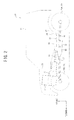
FIG. 3 is a view depicting the one embodiment of a hybrid four-wheel drive vehicle according to the present invention or a skeleton diagram of a torque transfer case coupled to a motor generator as viewed from above the vehicle. -
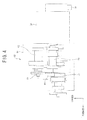
FIG. 4 is a view depicting the one embodiment of a hybrid four-wheel drive vehicle according to the present invention or a side view of the torque transfer case coupled to the motor generator as viewed from one side of the vehicle. -
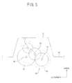
FIG. 5 is a view depicting the one embodiment of a hybrid four-wheel drive vehicle according to the present invention or a rear view of the torque transfer case coupled to the motor generator as viewed from behind the vehicle. - Referring to the drawings, one embodiment of a hybrid four-wheel drive vehicle according to the present invention is described below.
FIGS. 1 to 5 are views depicting the embodiment of hybrid four-wheel drive vehicle according to the present invention. - First, the construction is described. In
FIGS. 1 and2 , a hybrid four-wheel drive vehicle 10 includes, on avehicle body 30, anengine 11 and amotor generator 50, as power sources, a pair ofrear traction wheels front traction wheels wheel drive vehicle 10 includes, onvehicle body 30, adriveline 40 which transmits power fromengine 11 andmotor generator 50 to onlyrear traction wheels rear traction wheels front traction wheels - Hybrid four-
wheel drive vehicle 10 is configured to travel by transmitting output power ofengine 11 andmotor generator 50 torear traction wheels front traction wheels driveline 40. -
Vehicle body 30 includes adash panel 31 and a floor panel of afront floor panel 32, afloor tunnel 33, avertical wall section 34 and arear floor panel 35. -
Dash panel 31 extends in almost vertical direction between an engine compartment in whichengine 11 is placed and a passenger compartment to serve as a partition between the engine compartment and the passenger compartment. - At the bottom of
vehicle body 30, there are providedfront floor panel 32 andrear floor panel 35 which constitute a floor of the passenger compartment.Front floor panel 32 constitutes that portion of the floor which extends forward from the middle ofvehicle body 30, whilerear floor panel 35 constitutes that portion of the floor which extends backward from the middle ofvehicle body 30. -
Vertical wall section 34 is provided at the rear end offront floor panel 32 and extends in an upward direction, and thisvertical wall section 34 has an upper end, to whichrear floor panel 35 is continuous. This makesrear floor panel 35 higher, in a vertical direction of the vehicle, thanfront floor panel 32. - Moreover,
floor tunnel 33 is provided almost at the middle offront floor panel 32 in a transverse direction of the vehicle in such a way that this floor tunnel protrudes upward and extends in a forward and rear direction of the vehicle. In addition to those described above,vehicle body 30 includes various kinds of support members (a sub-frame and the like) which supportengine 11 andtransmission 12. -
Engine 11 is an internal combustion engine which operates on combustion of fuel, and it is longitudinally mounted, in a backward tilting position, at the front part ofvehicle body 30. - Driveline 40 includes
transmission 12 as a gearbox, afirst propeller shaft 13, atorque transfer case 60, asecond propeller shaft 15 and athird propeller shaft 17. Moreover,driveline 40 includes: arear differential 16; afront differential 18;front traction wheels rear traction wheels -
Transmission 12 is coupled to the rear end ofengine 11 and configured to convert, using gears, not shown, input power fed byengine 11 to provide an output.Transmission 12 is located, in a backward tilting position, belowfloor tunnel 33.Transmission 12 may be constituted by an automatic transmission or a manual transmission. -
Torque transfer case 60 is coupled totransmission 12 from behind throughfirst propeller shaft 13.Torque transfer case 60 is located belowfront floor panel 32 and almost at the middle with respect to the forward and rear direction of the vehicle.First propeller shaft 13 is coupled totorque transfer case 60 after passing through a front wall surface which is situated on the left-hand side with respect to a transverse direction of the vehicle and on the upper side with respect to a vertical direction of the vehicle. -
Second propeller shaft 15 for transmission of power torear traction wheels torque transfer case 60 after passing through a rear outer wall which is situated on the right-hand side with respect to the transverse direction of the vehicle and on the lower side with respect to the vertical direction of the vehicle. - Moreover,
third propeller shaft 17 for transmission of power tofront traction wheels torque transfer case 60 after passing through a front outer wall which is situated on the right-hand side with respect to the transverse direction of the vehicle and on the lower side with respect to the vertical direction of the vehicle. - These
second propeller shaft 15 andthird propeller shaft 17 are disposed on an axis which is offset in the transverse direction of the vehicle from an axis offirst propeller shaft 13. - A
motor generator 50 is coupled totorque transfer case 60 after passing through a rear outer wall which is situated on the left-hand side with respect to the transverse direction of the vehicle and on the lower side with respect to the vertical direction of the vehicle. In other words, with respect to the rear outer wall oftorque transfer case 60,motor generator 50 is coupled totorque transfer case 60 from that side of the rear outer wall which is located behind, as viewed from above the vehicle,first propeller shaft 13. -
Motor generator 50, when serving as a traction motor, can produce driving power for propelling by using electricity from a battery, not shown, to provide the produced driving power totorque transfer case 60 for transmission of driving power only torear traction wheels rear traction wheels front traction wheels - Moreover,
motor generator 50, when serving as a generator, can generate electricity by being rotated by driving power fed fromtorque transfer case 60.Motor generator 50 for the present embodiment constitutes a rotary electric machine in the present invention. - There is provided a
rear differential 16 at a rear end ofsecond propeller shaft 15, and thisrear differential 16 is configured to distribute driving power fromsecond propeller shaft 15 to left and rightrear traction wheels rear traction wheels - There is provided a
front differential 18 at a front end ofthird propeller shaft 17, and thisfront differential 18 is configured to distribute driving power fromthird propeller shaft 17 to left and rightfront traction wheels front traction wheels - Referring to
FIG. 3 ,torque transfer case 60 includes atransfer housing 61, and apowertrain input shaft 62, which works as a first input shaft, is rotatably supported on a left-side front end portion within thistransfer housing 61. - At the front end,
powertrain input shaft 62 is coupled to the rear end offirst propeller shaft 13 through a joint 13a. Moreover, adrive gear 63 is fixedly coupled topowertrain input shaft 62. - A motor
generator input shaft 69, which works as a second input shaft, is rotatably supported on a left-side rear end portion within thistransfer housing 61. At the rear end, motorgenerator input shaft 69 is coupled tomotor generator 50. Adrive gear 70 is fixedly coupled to motorgenerator input shaft 69. - A
counter shaft 64 is rotatably supported about its axis on almost the middle portion in the transverse direction of the vehicle withintransfer housing 61. Driven gears 65, 68 are fixedly coupled to countershaft 64. - Driven gears 65 and 68 engage
drive gear 63 onpowertrain input shaft 62 and drivegear 70 on motorgenerator input shaft 69, respectively. Drive gears 63, 70 and drivengears shaft 64. - An
output shaft 71 is rotatably supported about its axis on the right-side portion withintransfer housing 61. Driven gears 72, 73 are provided aroundoutput shaft 71, and these drivengears - Driven
gear 72 and drivegear 66 constitute afirst gear train 75 configured to provide a high speed stage, and drivengear 73 and drivegear 67 constitute asecond gear train 76 configured to provide a low speed stage. - Moreover, at the rear end,
output shaft 71 is coupled to the front end ofsecond propeller shaft 15 through a joint 15a, and at the front end,output shaft 71 is coupled to the rear end ofthird propeller shaft 17 through a joint 17a. - On the side in which the front end of
output shaft 71 is, there is provided a 2WD-4WD switching mechanism 77. 2WD-4WD switching mechanism 77 is configured to engage its friction engagement element when it is operated by a vehicle driver to switch to 4WD position. - When 2WD-
4WD switching mechanism 77 is operated to switch to 4WD position, torque ofoutput shaft 71 is delivered to both of thesecond propeller shaft 15 andthird propeller shaft 17, and the vehicle becomes operable in 4WD mode. - Moreover, 2WD-
4WD switching mechanism 77 is configured to disengage its friction engagement element when it is operated by a vehicle driver to switch to 2WD position. When 2WD-4WD switching mechanism 77 is operated to switch to 2WD position, torque ofoutput shaft 71 is delivered to only thesecond propeller shaft 15, and the vehicle becomes operable in 2WD mode. - Moreover, a
sleeve 74 is provided onoutput shaft 71 andsleeve 74 is configured to move onoutput shaft 71 in forward and backward direction by switching operation by a vehicle driver. Whensleeve 74 is operated to switch to a high speed position after being moved onoutput shaft 71 in forward direction, drivengear 72 is brought into rotation withoutput shaft 71 thereby to provide high speed stage in cooperation withdrive gear 66. - Moreover, when
sleeve 74 is operated to switch to a low speed position after being moved onoutput shaft 71 in backward direction, drivengear 73 is brought into rotation withoutput shaft 71 thereby to provide low speed stage in cooperation withdrive gear 67. - Moreover, when
sleeve 74 is operated to switch to a neutral position between the high speed position and the low speed position, driven gears 72, 73 are brought into relative rotation tooutput shaft 71 thereby to interrupt power delivery betweenoutput shaft 71 andcounter shaft 64. - Therefore, driving power may be delivered from
powertrain input shaft 62 and motorgenerator input shaft 69 tooutput shaft 71 through a gear train including drive gears 63, 70, driven gears 65, 68, drive gears 66, 67 and drivengears - As readily seen from the above,
sleeve 74,first gear train 75 andsecond gear train 76 constitute ashift mechanism 78 which is configured to enable a shift between the driving power delivery mode (that is, a mode in which the high speed stage or low speed stage is provided) in which driving power is transmitted fromcounter shaft 64 tooutput shaft 71 through eitherfirst gear train 75 orsecond gear train 76, and the neutral mode in which driving power is not transmitted fromcounter shaft 64 tooutput shaft 71. - In the present embodiment, when
shift mechanism 78 is caused to shift into the neutral mode,motor generator 50 is driven to generate electricity by driving power produced byengine 11 transmitted to motorgenerator input shaft 69 frompowertrain input shaft 62 throughcounter shaft 64. - Moreover, in the present embodiment, motor
generator input shaft 69 is located belowpowertrain input shaft 62 when viewing, inFIG. 4 ,torque transfer case 60 from the side of vehicle and viewing, inFIG. 5 ,torque transfer case 60 in an axial direction (that is, a direction of an axis) along an axis ofpowertrain input shaft 62, an axis of motorgenerator input shaft 69 and an axis ofoutput shaft 71. - Moreover, in
FIG. 4 , apower supply cable 79 is connected to the rear part ofmotor generator 50 for supply of power from a battery. - Next, operation is described. When it becomes operable in the driving power delivery mode by
sleeve 74 ofshift mechanism 78 andmotor generator 50 is powered by the battery, hybrid four-wheel drive vehicle 10 can travel by both driving power produced byengine 11 and driving power produced bymotor generator 50. - In the present embodiment, with respect to the rear outer wall of
torque transfer case 60,motor generator 50 is coupled totorque transfer case 60 from that side of the rear outer wall which is located behind, as viewed from above hybrid four-wheel drive vehicle 10, thefirst propeller shaft 13. - According to this,
motor generator 50 is coupled to the rear outer wall oftorque transfer case 60 which is located belowfront floor panel 32, so that, without remodeling the floor panel of an existing non-hybrid four-wheel drive vehicle, a relatively large, in outer diameter, high-output motor generator may be installed at a low position below the floor panel. This improves travelling performance of hybrid four-wheel drive vehicle 10 by lowering the center of gravity and souping up the hybrid four-wheel drive vehicle bysuch motor generator 50. - Moreover,
motor generator 50 is coupled to the rear outer wall oftorque transfer case 60 located behind, as viewed from above hybrid fourwheel drive vehicle 10, thefirst propeller shaft 13, so thatmotor generator 50 may be coupled totorque transfer case 60 without changing the locations of thefirst propeller shaft 13,second propeller shaft 15 andthird propeller shaft 17. - Furthermore,
motor generator 50 is not provided insidetorque transfer case 60 but coupled totorque transfer case 60 from the exterior of the rear outer wall,power supply cable 79 may be connected tomotor generator 50 without drastically remodelingtransfer housing 61. - As a result, hybrid four-
wheel drive vehicle 10 may be fabricated from an existing non-hybrid four-wheel drive vehicle equipped with a torque transfer case without any drastic modification, and travelling performance of hybrid four-wheel drive vehicle 10 may be improved. - Moreover, in the present embodiment, motor
generator input shaft 69 is located belowpowertrain input shaft 62 when viewingtorque transfer case 60 in an axial direction along an axis ofpowertrain input shaft 62, an axis of motorgenerator input shaft 69 and an axis ofoutput shaft 71. - According to this, motor
generator input shaft 69 coupled tomotor generator 50 is located belowpowertrain input shaft 62 coupled to thefirst propeller shaft 13, so that the distance tovehicle body 30, i.e.,front floor panel 32 andfloor tunnel 33, from motorgenerator input shaft 69 may be increased. Thus, a large, in outer diameter,motor generator 50 may be installed to hybrid four-wheel drive vehicle 10. - Moreover, in the present embodiment, when
shift mechanism 78 is caused to shift into the neutral mode,motor generator 50 is driven to generate electricity by driving power produced byengine 11 transmitted to motorgenerator input shaft 69 frompowertrain input shaft 62 throughcounter shaft 64. - According to this, even when the vehicle is at a halt with
shift mechanism 78 caused to shift into the neutral mode,motor generator 50 can generate electric power by being driven by driving power produced byengine 11 which is transmitted frompowertrain input shaft 62 to motorgenerator input shaft 69 throughcounter shaft 64. - Although an embodiment of the present invention has been described, it will be apparent to person skilled in the art that modifications may be made without departing from the scope of the present invention. All such modifications and equivalents thereof are intended to be covered by the following claims described in scope of claims.
- 10...Hybrid four-wheel drive vehicle, 11...Engine, 12...Transmission (Gearbox), 13...First propeller shaft, 15...Second propeller shaft, 17...Third propeller shaft, 20R, 20L...Front traction wheels, 22R, 22L...Rear traction wheels, 32...Front floor panel (Floor panel), 50...Motor generator (Rotary electric machine), 60...Torque transfer case, 61...Transfer case housing, 62...Powertrain input shaft (First input shaft), 63...Drive gear (Gear train), 64...Counter shaft, 65...Driven gear (Gear train), 66...Drive gear (Gear train), 67...Drive gear (Gear train), 69...Motor generator input shaft (Second input shaft), 70...Drive gear (Gear train), 71...Output shaft, 72...Driven gear (Gear train), 73...Driven gear (Gear train), 75...First gear train (Gear train), 76...Second gear train (Gear train), 78...Shift mechanism.
Claims (3)
- A hybrid four-wheel drive vehicle including:an engine;a transmission coupled to a rear end of the engine;a torque transfer case coupled to the transmission from behind through a first propeller shaft and located below a floor panel;a second propeller shaft for transmission of driving power from the torque transfer case to rear traction wheels;a third propeller shaft for transmission of driving power from the torque transfer case to front traction wheels; anda rotary electric machine which can transmit driving power to the rear traction wheels and the front traction wheels,the second propeller shaft and the third propeller shaft being disposed on an axis which is offset in the transverse direction of the vehicle from an axis of the first propeller shaft,characterized in that, with respect to a rear outer wall of the torque transfer case, the rotary electric machine is coupled to the torque transfer case from that side of the rear outer wall which is located behind, as viewed from above the vehicle, the first propeller shaft.
- The hybrid four-wheel drive vehicle according to claim 1, wherein
the torque transfer case comprises:a first input shaft coupled to the first propeller shaft;a second input shaft coupled to the rotary electric machine; andan output shaft, which may be given driving power transmitted from the first and second input shaft through a gear train, connectable to the second propeller shaft and the third propeller shaft, whereinthe second input shaft is located below the first input shaft when viewing the torque transfer case in an axial direction along an axis of the first input shaft, an axis of the second input shaft and an axis of the output shaft. - The hybrid four-wheel drive vehicle according to claim 2, wherein
the torque transfer case comprises:a counter shaft, which may be given driving power transmitted from the first and second input shaft through an input gear train working as the gear train; anda shift mechanism, located between the counter shaft and the output shaft, configured to enable a shift between a driving power delivery mode in which driving power is transmitted from the counter shaft to the output shaft through either a first gear train or a second gear train, which works as the gear train, and a neutral mode in which driving power is not transmitted from the counter shaft to the output shaft, whereinwhen the shift mechanism is caused to shift into the neutral mode, the rotary electric machine is driven to generate electricity by driving power produced by the engine transmitted to the second input shaft from the first input shaft through the counter shaft.
Applications Claiming Priority (2)
| Application Number | Priority Date | Filing Date | Title |
|---|---|---|---|
| JP2014074155A JP2015196413A (en) | 2014-03-31 | 2014-03-31 | hybrid four-wheel-drive vehicle |
| PCT/JP2015/056497 WO2015151712A1 (en) | 2014-03-31 | 2015-03-05 | Hybrid four-wheel-drive vehicle |
Publications (3)
| Publication Number | Publication Date |
|---|---|
| EP2949495A1 true EP2949495A1 (en) | 2015-12-02 |
| EP2949495A4 EP2949495A4 (en) | 2016-04-20 |
| EP2949495B1 EP2949495B1 (en) | 2016-12-28 |
Family
ID=54240045
Family Applications (1)
| Application Number | Title | Priority Date | Filing Date |
|---|---|---|---|
| EP15736368.0A Active EP2949495B1 (en) | 2014-03-31 | 2015-03-05 | Hybrid four-wheel-drive vehicle |
Country Status (4)
| Country | Link |
|---|---|
| EP (1) | EP2949495B1 (en) |
| JP (1) | JP2015196413A (en) |
| CN (1) | CN105517670A (en) |
| WO (1) | WO2015151712A1 (en) |
Cited By (7)
| Publication number | Priority date | Publication date | Assignee | Title |
|---|---|---|---|---|
| DE102016103377A1 (en) | 2016-02-25 | 2017-08-31 | Airbus Operations Gmbh | Waste compacting system and vehicle with a waste compacting system |
| FR3066799A1 (en) * | 2017-05-29 | 2018-11-30 | Suzuki Motor Corporation | STRUCTURE FOR SUPPORTING A SPEED CHANGE MECHANISM |
| DE102018203338A1 (en) * | 2018-03-06 | 2019-09-12 | Magna powertrain gmbh & co kg | powertrain |
| US10434738B2 (en) | 2014-05-28 | 2019-10-08 | Airbus Operations Gmbh | Waste compaction system for a vehicle, cabin monument for a vehicle having such a waste compaction system and vehicle having at least one waste compaction system |
| US10940946B2 (en) | 2015-05-05 | 2021-03-09 | Airbus Operations Gmbh | System for disposing waste products in a means of transportation |
| US11046169B2 (en) | 2017-04-21 | 2021-06-29 | Toyota Jidosha Kabushiki Kaisha | Four-wheel drive hybrid vehicle |
| US11180017B2 (en) | 2015-08-07 | 2021-11-23 | Denso Corporation | Device for driving vehicle |
Families Citing this family (11)
| Publication number | Priority date | Publication date | Assignee | Title |
|---|---|---|---|---|
| JP2015196413A (en) * | 2014-03-31 | 2015-11-09 | スズキ株式会社 | hybrid four-wheel-drive vehicle |
| WO2017026242A1 (en) * | 2015-08-07 | 2017-02-16 | 株式会社デンソー | Device for driving vehicle |
| JP2017036026A (en) * | 2015-08-07 | 2017-02-16 | 株式会社デンソー | Driving apparatus of vehicle |
| DE102015014814B4 (en) | 2015-11-14 | 2023-03-23 | Audi Ag | Drive device for a motor vehicle |
| EP3468823B1 (en) | 2016-06-14 | 2024-09-04 | Polaris Industries Inc. | Hybrid utility vehicle |
| WO2020031313A1 (en) * | 2018-08-09 | 2020-02-13 | 株式会社ユニバンス | Power transmitting device |
| US10780770B2 (en) | 2018-10-05 | 2020-09-22 | Polaris Industries Inc. | Hybrid utility vehicle |
| US11370266B2 (en) | 2019-05-16 | 2022-06-28 | Polaris Industries Inc. | Hybrid utility vehicle |
| WO2020240736A1 (en) * | 2019-05-29 | 2020-12-03 | 日産自動車株式会社 | Hybrid electric vehicle |
| JP7487717B2 (en) * | 2021-09-30 | 2024-05-21 | 株式会社アイシン | Transfer Device |
| JP2023051249A (en) * | 2021-09-30 | 2023-04-11 | 株式会社アイシン | Transfer device |
Family Cites Families (17)
| Publication number | Priority date | Publication date | Assignee | Title |
|---|---|---|---|---|
| US2850920A (en) * | 1950-12-21 | 1958-09-09 | Rockwell Spring & Axle Co | Vehicle drive mechanism |
| JPS5398629A (en) * | 1977-02-05 | 1978-08-29 | Kenichi Kon | Electric motor car with selffcharging system using jointly recipro engine |
| GB2346124A (en) * | 1999-01-27 | 2000-08-02 | Rover Group | Hybrid vehicle powertrain control |
| JP2002206639A (en) * | 2000-11-08 | 2002-07-26 | Hitachi Ltd | Automatic transmissions and vehicles |
| JP2007010158A (en) * | 2000-11-08 | 2007-01-18 | Hitachi Ltd | vehicle |
| JP3646705B2 (en) | 2002-02-15 | 2005-05-11 | 日産自動車株式会社 | Electric motor mounting structure for hybrid four-wheel drive vehicles |
| JP2005001567A (en) * | 2003-06-12 | 2005-01-06 | Fuji Heavy Ind Ltd | Vehicle traveling device |
| JP2005029063A (en) * | 2003-07-09 | 2005-02-03 | Toyota Motor Corp | Hybrid vehicle drive system |
| FR2884459B1 (en) * | 2005-04-14 | 2008-09-19 | Peugeot Citroen Automobiles Sa | HYBRID TRACTION CHAIN AND HYBRID VEHICLE EQUIPPED WITH SUCH A HYBRID TRACTION CHAIN |
| CN101559709A (en) * | 2009-05-12 | 2009-10-21 | 朱豪 | Special automobile dynamic distribution method |
| JP2011173440A (en) * | 2010-02-23 | 2011-09-08 | Aisin Ai Co Ltd | Power transmitting device for four-wheel drive hybrid-vehicle |
| EP2450597A1 (en) * | 2010-11-09 | 2012-05-09 | Technische Universität Darmstadt | Invention relating to electric drive |
| JP5505335B2 (en) * | 2011-02-28 | 2014-05-28 | 株式会社デンソー | Power transmission device for vehicle |
| GB201201221D0 (en) * | 2012-01-25 | 2012-03-07 | Jaguar Cars | Hybrid electric vehicle and method of control thereof |
| EP2705968B1 (en) * | 2012-09-06 | 2017-11-29 | IVECO S.p.A. | Vehicle comprising a two-shaft torque distributor, control method therefor, computer program and computer-readable means |
| CN203283020U (en) * | 2013-04-28 | 2013-11-13 | 长城汽车股份有限公司 | Hybrid power speed changer and corresponding automobile |
| JP2015196413A (en) * | 2014-03-31 | 2015-11-09 | スズキ株式会社 | hybrid four-wheel-drive vehicle |
-
2014
- 2014-03-31 JP JP2014074155A patent/JP2015196413A/en active Pending
-
2015
- 2015-03-05 CN CN201580000098.3A patent/CN105517670A/en active Pending
- 2015-03-05 EP EP15736368.0A patent/EP2949495B1/en active Active
- 2015-03-05 WO PCT/JP2015/056497 patent/WO2015151712A1/en not_active Ceased
Cited By (7)
| Publication number | Priority date | Publication date | Assignee | Title |
|---|---|---|---|---|
| US10434738B2 (en) | 2014-05-28 | 2019-10-08 | Airbus Operations Gmbh | Waste compaction system for a vehicle, cabin monument for a vehicle having such a waste compaction system and vehicle having at least one waste compaction system |
| US10940946B2 (en) | 2015-05-05 | 2021-03-09 | Airbus Operations Gmbh | System for disposing waste products in a means of transportation |
| US11180017B2 (en) | 2015-08-07 | 2021-11-23 | Denso Corporation | Device for driving vehicle |
| DE102016103377A1 (en) | 2016-02-25 | 2017-08-31 | Airbus Operations Gmbh | Waste compacting system and vehicle with a waste compacting system |
| US11046169B2 (en) | 2017-04-21 | 2021-06-29 | Toyota Jidosha Kabushiki Kaisha | Four-wheel drive hybrid vehicle |
| FR3066799A1 (en) * | 2017-05-29 | 2018-11-30 | Suzuki Motor Corporation | STRUCTURE FOR SUPPORTING A SPEED CHANGE MECHANISM |
| DE102018203338A1 (en) * | 2018-03-06 | 2019-09-12 | Magna powertrain gmbh & co kg | powertrain |
Also Published As
| Publication number | Publication date |
|---|---|
| EP2949495B1 (en) | 2016-12-28 |
| WO2015151712A1 (en) | 2015-10-08 |
| EP2949495A4 (en) | 2016-04-20 |
| CN105517670A (en) | 2016-04-20 |
| JP2015196413A (en) | 2015-11-09 |
Similar Documents
| Publication | Publication Date | Title |
|---|---|---|
| EP2949495B1 (en) | Hybrid four-wheel-drive vehicle | |
| US9694662B2 (en) | Vehicle electric and mechanical drive train | |
| KR101912980B1 (en) | Drive train of a solely electrically driven motor vehicle having two electric motors | |
| US10514087B2 (en) | Driving system | |
| JP6224609B2 (en) | Purely all-wheel drive car drivetrain | |
| JP6390105B2 (en) | Drive device for hybrid vehicle | |
| US7832514B2 (en) | Axle drive unit for a hybrid electric vehicle | |
| US10308105B2 (en) | Drive device for a hybrid-driven motor vehicle | |
| JP6481193B2 (en) | Electric vehicle | |
| KR20170133437A (en) | Electric axle | |
| CN101801701A (en) | Drive train for a motor vehicle | |
| CN104442341A (en) | A rear drive unit for a hybrid electric motor vehicle | |
| KR101694037B1 (en) | Power train for Electric vehicle | |
| KR20190078637A (en) | Vehicle drive system, method of providing 4-wheel drive axle and 4-wheel drive axle | |
| KR101345954B1 (en) | Driving device for rear wheels of 4 Wheel Driving Electric Vehicle | |
| CN111183054A (en) | Power transmission for four-wheel drive vehicles | |
| JP2019513619A (en) | Vehicle driveline system | |
| KR20130084185A (en) | Auxiliary transmission driver of the 4 wheel drive vehicle | |
| CN102917902B (en) | Hybrid powertrain | |
| JP4038469B2 (en) | Hybrid vehicle structure | |
| JP2006082748A (en) | Power output device and automobile equipped with the same | |
| CN201031945Y (en) | Drive input transition gear box assembly of roller tractor | |
| CN104648140A (en) | Drive device applied to rear wheel of four-wheel drive electric vehicle | |
| KR20160038295A (en) | 4-wheels drive electric vehicle |
Legal Events
| Date | Code | Title | Description |
|---|---|---|---|
| PUAI | Public reference made under article 153(3) epc to a published international application that has entered the european phase |
Free format text: ORIGINAL CODE: 0009012 |
|
| 17P | Request for examination filed |
Effective date: 20150810 |
|
| AK | Designated contracting states |
Kind code of ref document: A1 Designated state(s): AL AT BE BG CH CY CZ DE DK EE ES FI FR GB GR HR HU IE IS IT LI LT LU LV MC MK MT NL NO PL PT RO RS SE SI SK SM TR |
|
| AX | Request for extension of the european patent |
Extension state: BA ME |
|
| A4 | Supplementary search report drawn up and despatched |
Effective date: 20160322 |
|
| RIC1 | Information provided on ipc code assigned before grant |
Ipc: B60K 6/52 20071001ALI20160316BHEP Ipc: B60L 11/14 20060101ALI20160316BHEP Ipc: B60K 6/48 20071001ALI20160316BHEP Ipc: B60K 6/547 20071001ALI20160316BHEP Ipc: B60K 6/40 20071001AFI20160316BHEP Ipc: B60W 20/00 20160101ALI20160316BHEP Ipc: B60K 6/36 20071001ALI20160316BHEP Ipc: B60W 10/10 20120101ALI20160316BHEP Ipc: B60K 17/344 20060101ALI20160316BHEP |
|
| GRAP | Despatch of communication of intention to grant a patent |
Free format text: ORIGINAL CODE: EPIDOSNIGR1 |
|
| DAV | Request for validation of the european patent (deleted) | ||
| DAX | Request for extension of the european patent (deleted) | ||
| INTG | Intention to grant announced |
Effective date: 20160921 |
|
| GRAS | Grant fee paid |
Free format text: ORIGINAL CODE: EPIDOSNIGR3 |
|
| STAA | Information on the status of an ep patent application or granted ep patent |
Free format text: STATUS: GRANT OF PATENT IS INTENDED |
|
| GRAA | (expected) grant |
Free format text: ORIGINAL CODE: 0009210 |
|
| STAA | Information on the status of an ep patent application or granted ep patent |
Free format text: STATUS: THE PATENT HAS BEEN GRANTED |
|
| AK | Designated contracting states |
Kind code of ref document: B1 Designated state(s): AL AT BE BG CH CY CZ DE DK EE ES FI FR GB GR HR HU IE IS IT LI LT LU LV MC MK MT NL NO PL PT RO RS SE SI SK SM TR |
|
| REG | Reference to a national code |
Ref country code: GB Ref legal event code: FG4D |
|
| REG | Reference to a national code |
Ref country code: CH Ref legal event code: EP |
|
| REG | Reference to a national code |
Ref country code: AT Ref legal event code: REF Ref document number: 856961 Country of ref document: AT Kind code of ref document: T Effective date: 20170115 |
|
| REG | Reference to a national code |
Ref country code: IE Ref legal event code: FG4D |
|
| REG | Reference to a national code |
Ref country code: DE Ref legal event code: R096 Ref document number: 602015001142 Country of ref document: DE |
|
| PG25 | Lapsed in a contracting state [announced via postgrant information from national office to epo] |
Ref country code: LV Free format text: LAPSE BECAUSE OF FAILURE TO SUBMIT A TRANSLATION OF THE DESCRIPTION OR TO PAY THE FEE WITHIN THE PRESCRIBED TIME-LIMIT Effective date: 20161228 |
|
| REG | Reference to a national code |
Ref country code: LT Ref legal event code: MG4D |
|
| PG25 | Lapsed in a contracting state [announced via postgrant information from national office to epo] |
Ref country code: NO Free format text: LAPSE BECAUSE OF FAILURE TO SUBMIT A TRANSLATION OF THE DESCRIPTION OR TO PAY THE FEE WITHIN THE PRESCRIBED TIME-LIMIT Effective date: 20170328 Ref country code: LT Free format text: LAPSE BECAUSE OF FAILURE TO SUBMIT A TRANSLATION OF THE DESCRIPTION OR TO PAY THE FEE WITHIN THE PRESCRIBED TIME-LIMIT Effective date: 20161228 Ref country code: GR Free format text: LAPSE BECAUSE OF FAILURE TO SUBMIT A TRANSLATION OF THE DESCRIPTION OR TO PAY THE FEE WITHIN THE PRESCRIBED TIME-LIMIT Effective date: 20170329 Ref country code: SE Free format text: LAPSE BECAUSE OF FAILURE TO SUBMIT A TRANSLATION OF THE DESCRIPTION OR TO PAY THE FEE WITHIN THE PRESCRIBED TIME-LIMIT Effective date: 20161228 |
|
| REG | Reference to a national code |
Ref country code: NL Ref legal event code: MP Effective date: 20161228 |
|
| REG | Reference to a national code |
Ref country code: AT Ref legal event code: MK05 Ref document number: 856961 Country of ref document: AT Kind code of ref document: T Effective date: 20161228 |
|
| PG25 | Lapsed in a contracting state [announced via postgrant information from national office to epo] |
Ref country code: RS Free format text: LAPSE BECAUSE OF FAILURE TO SUBMIT A TRANSLATION OF THE DESCRIPTION OR TO PAY THE FEE WITHIN THE PRESCRIBED TIME-LIMIT Effective date: 20161228 Ref country code: FI Free format text: LAPSE BECAUSE OF FAILURE TO SUBMIT A TRANSLATION OF THE DESCRIPTION OR TO PAY THE FEE WITHIN THE PRESCRIBED TIME-LIMIT Effective date: 20161228 Ref country code: HR Free format text: LAPSE BECAUSE OF FAILURE TO SUBMIT A TRANSLATION OF THE DESCRIPTION OR TO PAY THE FEE WITHIN THE PRESCRIBED TIME-LIMIT Effective date: 20161228 |
|
| PG25 | Lapsed in a contracting state [announced via postgrant information from national office to epo] |
Ref country code: NL Free format text: LAPSE BECAUSE OF FAILURE TO SUBMIT A TRANSLATION OF THE DESCRIPTION OR TO PAY THE FEE WITHIN THE PRESCRIBED TIME-LIMIT Effective date: 20161228 |
|
| PG25 | Lapsed in a contracting state [announced via postgrant information from national office to epo] |
Ref country code: RO Free format text: LAPSE BECAUSE OF FAILURE TO SUBMIT A TRANSLATION OF THE DESCRIPTION OR TO PAY THE FEE WITHIN THE PRESCRIBED TIME-LIMIT Effective date: 20161228 Ref country code: IS Free format text: LAPSE BECAUSE OF FAILURE TO SUBMIT A TRANSLATION OF THE DESCRIPTION OR TO PAY THE FEE WITHIN THE PRESCRIBED TIME-LIMIT Effective date: 20170428 Ref country code: EE Free format text: LAPSE BECAUSE OF FAILURE TO SUBMIT A TRANSLATION OF THE DESCRIPTION OR TO PAY THE FEE WITHIN THE PRESCRIBED TIME-LIMIT Effective date: 20161228 Ref country code: SK Free format text: LAPSE BECAUSE OF FAILURE TO SUBMIT A TRANSLATION OF THE DESCRIPTION OR TO PAY THE FEE WITHIN THE PRESCRIBED TIME-LIMIT Effective date: 20161228 Ref country code: CZ Free format text: LAPSE BECAUSE OF FAILURE TO SUBMIT A TRANSLATION OF THE DESCRIPTION OR TO PAY THE FEE WITHIN THE PRESCRIBED TIME-LIMIT Effective date: 20161228 |
|
| PG25 | Lapsed in a contracting state [announced via postgrant information from national office to epo] |
Ref country code: BG Free format text: LAPSE BECAUSE OF FAILURE TO SUBMIT A TRANSLATION OF THE DESCRIPTION OR TO PAY THE FEE WITHIN THE PRESCRIBED TIME-LIMIT Effective date: 20170328 Ref country code: PT Free format text: LAPSE BECAUSE OF FAILURE TO SUBMIT A TRANSLATION OF THE DESCRIPTION OR TO PAY THE FEE WITHIN THE PRESCRIBED TIME-LIMIT Effective date: 20170428 Ref country code: SM Free format text: LAPSE BECAUSE OF FAILURE TO SUBMIT A TRANSLATION OF THE DESCRIPTION OR TO PAY THE FEE WITHIN THE PRESCRIBED TIME-LIMIT Effective date: 20161228 Ref country code: AT Free format text: LAPSE BECAUSE OF FAILURE TO SUBMIT A TRANSLATION OF THE DESCRIPTION OR TO PAY THE FEE WITHIN THE PRESCRIBED TIME-LIMIT Effective date: 20161228 Ref country code: IT Free format text: LAPSE BECAUSE OF FAILURE TO SUBMIT A TRANSLATION OF THE DESCRIPTION OR TO PAY THE FEE WITHIN THE PRESCRIBED TIME-LIMIT Effective date: 20161228 Ref country code: BE Free format text: LAPSE BECAUSE OF FAILURE TO SUBMIT A TRANSLATION OF THE DESCRIPTION OR TO PAY THE FEE WITHIN THE PRESCRIBED TIME-LIMIT Effective date: 20161228 Ref country code: ES Free format text: LAPSE BECAUSE OF FAILURE TO SUBMIT A TRANSLATION OF THE DESCRIPTION OR TO PAY THE FEE WITHIN THE PRESCRIBED TIME-LIMIT Effective date: 20161228 Ref country code: PL Free format text: LAPSE BECAUSE OF FAILURE TO SUBMIT A TRANSLATION OF THE DESCRIPTION OR TO PAY THE FEE WITHIN THE PRESCRIBED TIME-LIMIT Effective date: 20161228 |
|
| REG | Reference to a national code |
Ref country code: DE Ref legal event code: R097 Ref document number: 602015001142 Country of ref document: DE |
|
| PLBE | No opposition filed within time limit |
Free format text: ORIGINAL CODE: 0009261 |
|
| STAA | Information on the status of an ep patent application or granted ep patent |
Free format text: STATUS: NO OPPOSITION FILED WITHIN TIME LIMIT |
|
| PG25 | Lapsed in a contracting state [announced via postgrant information from national office to epo] |
Ref country code: MC Free format text: LAPSE BECAUSE OF FAILURE TO SUBMIT A TRANSLATION OF THE DESCRIPTION OR TO PAY THE FEE WITHIN THE PRESCRIBED TIME-LIMIT Effective date: 20161228 Ref country code: DK Free format text: LAPSE BECAUSE OF FAILURE TO SUBMIT A TRANSLATION OF THE DESCRIPTION OR TO PAY THE FEE WITHIN THE PRESCRIBED TIME-LIMIT Effective date: 20161228 |
|
| 26N | No opposition filed |
Effective date: 20170929 |
|
| REG | Reference to a national code |
Ref country code: IE Ref legal event code: MM4A |
|
| REG | Reference to a national code |
Ref country code: FR Ref legal event code: ST Effective date: 20171130 |
|
| PG25 | Lapsed in a contracting state [announced via postgrant information from national office to epo] |
Ref country code: LU Free format text: LAPSE BECAUSE OF NON-PAYMENT OF DUE FEES Effective date: 20170305 Ref country code: FR Free format text: LAPSE BECAUSE OF NON-PAYMENT OF DUE FEES Effective date: 20170331 |
|
| PG25 | Lapsed in a contracting state [announced via postgrant information from national office to epo] |
Ref country code: SI Free format text: LAPSE BECAUSE OF FAILURE TO SUBMIT A TRANSLATION OF THE DESCRIPTION OR TO PAY THE FEE WITHIN THE PRESCRIBED TIME-LIMIT Effective date: 20161228 Ref country code: IE Free format text: LAPSE BECAUSE OF NON-PAYMENT OF DUE FEES Effective date: 20170305 |
|
| PG25 | Lapsed in a contracting state [announced via postgrant information from national office to epo] |
Ref country code: MT Free format text: LAPSE BECAUSE OF NON-PAYMENT OF DUE FEES Effective date: 20170305 |
|
| REG | Reference to a national code |
Ref country code: CH Ref legal event code: PL |
|
| RIC2 | Information provided on ipc code assigned after grant |
Ipc: B60K 6/52 20071001ALI20160316BHEP Ipc: B60L 11/14 20060101ALI20160316BHEP Ipc: B60W 10/10 20120101ALI20160316BHEP Ipc: B60K 17/344 20060101ALI20160316BHEP Ipc: B60K 6/36 20071001ALI20160316BHEP Ipc: B60W 20/00 20160101ALI20160316BHEP Ipc: B60K 6/48 20071001ALI20160316BHEP Ipc: B60K 6/547 20071001ALI20160316BHEP Ipc: B60K 6/40 20071001AFI20160316BHEP |
|
| PG25 | Lapsed in a contracting state [announced via postgrant information from national office to epo] |
Ref country code: CH Free format text: LAPSE BECAUSE OF NON-PAYMENT OF DUE FEES Effective date: 20180331 Ref country code: LI Free format text: LAPSE BECAUSE OF NON-PAYMENT OF DUE FEES Effective date: 20180331 |
|
| PG25 | Lapsed in a contracting state [announced via postgrant information from national office to epo] |
Ref country code: HU Free format text: LAPSE BECAUSE OF FAILURE TO SUBMIT A TRANSLATION OF THE DESCRIPTION OR TO PAY THE FEE WITHIN THE PRESCRIBED TIME-LIMIT; INVALID AB INITIO Effective date: 20150305 |
|
| PG25 | Lapsed in a contracting state [announced via postgrant information from national office to epo] |
Ref country code: CY Free format text: LAPSE BECAUSE OF FAILURE TO SUBMIT A TRANSLATION OF THE DESCRIPTION OR TO PAY THE FEE WITHIN THE PRESCRIBED TIME-LIMIT Effective date: 20161228 |
|
| GBPC | Gb: european patent ceased through non-payment of renewal fee |
Effective date: 20190305 |
|
| PG25 | Lapsed in a contracting state [announced via postgrant information from national office to epo] |
Ref country code: MK Free format text: LAPSE BECAUSE OF FAILURE TO SUBMIT A TRANSLATION OF THE DESCRIPTION OR TO PAY THE FEE WITHIN THE PRESCRIBED TIME-LIMIT Effective date: 20161228 |
|
| PG25 | Lapsed in a contracting state [announced via postgrant information from national office to epo] |
Ref country code: GB Free format text: LAPSE BECAUSE OF NON-PAYMENT OF DUE FEES Effective date: 20190305 |
|
| PG25 | Lapsed in a contracting state [announced via postgrant information from national office to epo] |
Ref country code: TR Free format text: LAPSE BECAUSE OF FAILURE TO SUBMIT A TRANSLATION OF THE DESCRIPTION OR TO PAY THE FEE WITHIN THE PRESCRIBED TIME-LIMIT Effective date: 20161228 |
|
| PG25 | Lapsed in a contracting state [announced via postgrant information from national office to epo] |
Ref country code: AL Free format text: LAPSE BECAUSE OF FAILURE TO SUBMIT A TRANSLATION OF THE DESCRIPTION OR TO PAY THE FEE WITHIN THE PRESCRIBED TIME-LIMIT Effective date: 20161228 |
|
| PGFP | Annual fee paid to national office [announced via postgrant information from national office to epo] |
Ref country code: DE Payment date: 20260128 Year of fee payment: 12 |