EP2949440A1 - Feeding carriage for compressor machine and use of same - Google Patents
Feeding carriage for compressor machine and use of same Download PDFInfo
- Publication number
- EP2949440A1 EP2949440A1 EP14807935.3A EP14807935A EP2949440A1 EP 2949440 A1 EP2949440 A1 EP 2949440A1 EP 14807935 A EP14807935 A EP 14807935A EP 2949440 A1 EP2949440 A1 EP 2949440A1
- Authority
- EP
- European Patent Office
- Prior art keywords
- feeding carriage
- front plate
- carriage
- geometry
- particulate material
- Prior art date
- Legal status (The legal status is an assumption and is not a legal conclusion. Google has not performed a legal analysis and makes no representation as to the accuracy of the status listed.)
- Granted
Links
Images





Classifications
-
- B—PERFORMING OPERATIONS; TRANSPORTING
- B28—WORKING CEMENT, CLAY, OR STONE
- B28B—SHAPING CLAY OR OTHER CERAMIC COMPOSITIONS; SHAPING SLAG; SHAPING MIXTURES CONTAINING CEMENTITIOUS MATERIAL, e.g. PLASTER
- B28B13/00—Feeding the unshaped material to moulds or apparatus for producing shaped articles; Discharging shaped articles from such moulds or apparatus
- B28B13/02—Feeding the unshaped material to moulds or apparatus for producing shaped articles
- B28B13/0215—Feeding the moulding material in measured quantities from a container or silo
- B28B13/026—Feeding the moulding material in measured quantities from a container or silo by using a movable hopper transferring the moulding material to the moulding cavities
-
- B—PERFORMING OPERATIONS; TRANSPORTING
- B30—PRESSES
- B30B—PRESSES IN GENERAL
- B30B15/00—Details of, or accessories for, presses; Auxiliary measures in connection with pressing
- B30B15/30—Feeding material to presses
- B30B15/302—Feeding material in particulate or plastic state to moulding presses
- B30B15/304—Feeding material in particulate or plastic state to moulding presses by using feed frames or shoes with relative movement with regard to the mould or moulds
-
- B—PERFORMING OPERATIONS; TRANSPORTING
- B29—WORKING OF PLASTICS; WORKING OF SUBSTANCES IN A PLASTIC STATE IN GENERAL
- B29C—SHAPING OR JOINING OF PLASTICS; SHAPING OF MATERIAL IN A PLASTIC STATE, NOT OTHERWISE PROVIDED FOR; AFTER-TREATMENT OF THE SHAPED PRODUCTS, e.g. REPAIRING
- B29C31/00—Handling, e.g. feeding of the material to be shaped, storage of plastics material before moulding; Automation, i.e. automated handling lines in plastics processing plants, e.g. using manipulators or robots
- B29C31/04—Feeding of the material to be moulded, e.g. into a mould cavity
-
- B—PERFORMING OPERATIONS; TRANSPORTING
- B65—CONVEYING; PACKING; STORING; HANDLING THIN OR FILAMENTARY MATERIAL
- B65G—TRANSPORT OR STORAGE DEVICES, e.g. CONVEYORS FOR LOADING OR TIPPING, SHOP CONVEYOR SYSTEMS OR PNEUMATIC TUBE CONVEYORS
- B65G11/00—Chutes
- B65G11/10—Chutes flexible
- B65G11/106—Chutes flexible for bulk
-
- B—PERFORMING OPERATIONS; TRANSPORTING
- B29—WORKING OF PLASTICS; WORKING OF SUBSTANCES IN A PLASTIC STATE IN GENERAL
- B29C—SHAPING OR JOINING OF PLASTICS; SHAPING OF MATERIAL IN A PLASTIC STATE, NOT OTHERWISE PROVIDED FOR; AFTER-TREATMENT OF THE SHAPED PRODUCTS, e.g. REPAIRING
- B29C43/00—Compression moulding, i.e. applying external pressure to flow the moulding material; Apparatus therefor
- B29C43/32—Component parts, details or accessories; Auxiliary operations
- B29C43/34—Feeding the material to the mould or the compression means
- B29C2043/3405—Feeding the material to the mould or the compression means using carrying means
- B29C2043/3427—Feeding the material to the mould or the compression means using carrying means hopper, vessel, chute, tube, conveying screw, for material in discrete form, e.g. particles or powder or fibres
-
- B—PERFORMING OPERATIONS; TRANSPORTING
- B29—WORKING OF PLASTICS; WORKING OF SUBSTANCES IN A PLASTIC STATE IN GENERAL
- B29C—SHAPING OR JOINING OF PLASTICS; SHAPING OF MATERIAL IN A PLASTIC STATE, NOT OTHERWISE PROVIDED FOR; AFTER-TREATMENT OF THE SHAPED PRODUCTS, e.g. REPAIRING
- B29C31/00—Handling, e.g. feeding of the material to be shaped, storage of plastics material before moulding; Automation, i.e. automated handling lines in plastics processing plants, e.g. using manipulators or robots
- B29C31/04—Feeding of the material to be moulded, e.g. into a mould cavity
- B29C31/06—Feeding of the material to be moulded, e.g. into a mould cavity in measured doses, e.g. by weighting
-
- B—PERFORMING OPERATIONS; TRANSPORTING
- B29—WORKING OF PLASTICS; WORKING OF SUBSTANCES IN A PLASTIC STATE IN GENERAL
- B29C—SHAPING OR JOINING OF PLASTICS; SHAPING OF MATERIAL IN A PLASTIC STATE, NOT OTHERWISE PROVIDED FOR; AFTER-TREATMENT OF THE SHAPED PRODUCTS, e.g. REPAIRING
- B29C43/00—Compression moulding, i.e. applying external pressure to flow the moulding material; Apparatus therefor
- B29C43/02—Compression moulding, i.e. applying external pressure to flow the moulding material; Apparatus therefor of articles of definite length, i.e. discrete articles
- B29C43/04—Compression moulding, i.e. applying external pressure to flow the moulding material; Apparatus therefor of articles of definite length, i.e. discrete articles using movable moulds
-
- B—PERFORMING OPERATIONS; TRANSPORTING
- B29—WORKING OF PLASTICS; WORKING OF SUBSTANCES IN A PLASTIC STATE IN GENERAL
- B29C—SHAPING OR JOINING OF PLASTICS; SHAPING OF MATERIAL IN A PLASTIC STATE, NOT OTHERWISE PROVIDED FOR; AFTER-TREATMENT OF THE SHAPED PRODUCTS, e.g. REPAIRING
- B29C43/00—Compression moulding, i.e. applying external pressure to flow the moulding material; Apparatus therefor
- B29C43/02—Compression moulding, i.e. applying external pressure to flow the moulding material; Apparatus therefor of articles of definite length, i.e. discrete articles
- B29C43/04—Compression moulding, i.e. applying external pressure to flow the moulding material; Apparatus therefor of articles of definite length, i.e. discrete articles using movable moulds
- B29C43/06—Compression moulding, i.e. applying external pressure to flow the moulding material; Apparatus therefor of articles of definite length, i.e. discrete articles using movable moulds continuously movable in one direction, e.g. mounted on chains, belts
- B29C43/08—Compression moulding, i.e. applying external pressure to flow the moulding material; Apparatus therefor of articles of definite length, i.e. discrete articles using movable moulds continuously movable in one direction, e.g. mounted on chains, belts with circular movement, e.g. mounted on rolls, turntables
Definitions
- the present invention generally relates to the field of compressor machines and more specifically to a feeding carriage for compressor machines.
- Compressor machines are widely used in different technical fields, such as, for example, in pharmacy, in the preparation of vitamins, compacted mechanical parts, microelectronics, etc. Compressor machines are used together with a feeding carriage, providing a mold of the compressor machine with the starting particulate material in which said particulate material is compressed for producing the final compressed article.
- Eccentric machines have a single mold, provided with one or more compression chambers and inserted in a part referred to as base plate. In such machines, the mold is fixed in place and the feeding carriage moves with a movement which allows filling the mold with particulate material, filling the mold completely, eliminating the remaining particulate material, and ejecting the final compressed article.
- Rotary compressor machines in turn have several molds and punches inserted in a circular movable base plate.
- the feeding carriage is fixed in place.
- the combination of one or more of the preceding mechanisms therefore causes the segregation or separation of different particles making up a starting particulate material as it moves from the feeding carriage to the mold of the compressor machine.
- a first segregation phenomenon can occur when filling the feeding carriage given that the particles fall at different speeds depending on their properties and also bounce off one another and the walls of the carriage in a different manner. Therefore, the properties of the particles (density, shape, size, etc.), the coefficients of friction (static and rolling) and the coefficient of restitution (in particle-particle and particle-carriage contacts), the carriage geometry, etc., affect this first segregation phenomenon.
- the continuous filling of the mold/molds also causes a segregation phenomenon, given that the particles move within the carriage at different speeds due to the aforementioned factors.
- the feeding carriage geometry influences said segregation phenomena.
- Patent document US 6764296 discloses a fluidizing method for fluidizing the content of a feeding carriage in order to reduce these segregation phenomena.
- the particulate materials are passed through a fluidizer which is partitioned by means of a distributor plate to form first and second chambers.
- the particulate materials pass through said first chamber which is in gaseous communication with said second chamber by means of the porous distributor plate.
- Gas is delivered to the second chamber at a pressure sufficient to generate a gas bearing between the porous distributor plate and the particulate material.
- the gas is allowed to migrate through the particulate material, and then be vented to the surrounding atmosphere without causing substantial turbulence in the particulate material.
- the present invention solves the problems of the prior art by disclosing a feeding carriage for a compressor machine the geometry of which can be changed depending on the properties and proportions of the particles making up the starting particulate material, such that segregation phenomena occurring within said feeding carriage are minimized.
- the present invention discloses a feeding carriage for a compressor machine of the type having an upper filling end through which a particulate material which is to be compressed in a mold of the compressor machine is introduced and a lower discharging end for discharging said particulate material towards said mold.
- At least some of the elements forming the feeding carriage of the present invention can move with respect to one another, which thereby allows modifying the geometry of at least one of said lower discharging end, said upper filling end and an intermediate portion of the feeding carriage located between both ends.
- move must be interpreted in a broad sense, said term being able to refer to "modifying" the position of the elements of the carriage in order to modify the geometry thereof, “changing the diameter” of the carriage in order to modify the geometry thereof or “changing” the section of the carriage, among other equivalent concepts.
- the present invention discloses use of a feeding carriage for a compressor machine according to the first aspect of the present invention.
- the use according to the second aspect of the present invention comprises the steps of:
- optimum carriage geometry can be determined by means of empirical tests or by means of computer simulation.
- compressor machines refers to machines used in any technical field for the preparation of compressed articles (pharmaceutical tablets, vitamins, parts for microelectronics, compacted structural parts, etc.) which can be fed with particulate material from a feeding carriage.
- articulate material refers to any type of material used for the preparation of articles compressed by means of compressor machines, regardless of the size and shape (cylindrical, spherical, etc.) thereof.
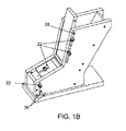
- FIGS 1A and 1B show a feeding carriage according to a first preferred embodiment of the present invention.
- This feeding carriage is formed by two side plates (10), two rear plates (12A, 12B) and a fixed lower front plate (14). These elements will remain fixed firmly in place for all the configurable feeding carriage geometries.
- the rear plates (12A, 12B) and the fixed lower front plate (14) are attached to the side plates (10) in a conventional manner by means of nuts and bolts.
- other attachment means such as welding, adhesives, etc., can be used.
- the feeding carriage further comprises a movable upper front plate (16), a first sliding front plate (18) and a second sliding front plate (20).
- the upper front plate (16) can be fixed to both side plates (10) by means of nuts and bolts (22) in a plurality of positions.
- the upper front plate (16) has a plurality of threaded holes (24).
- the side plates (10) have a pair of grooves (26). The nuts and bolts are introduced through the grooves (26) into the threaded holes (24) for fixing the upper front plate (16) to the side plates (10) in the desired position.
- the first sliding front plate (18) is in turn attached to the upper front plate (16) by means of a hinge (28) which allows changing the angle of inclination formed between both, thereby providing one more degree of freedom for changing the feeding carriage geometry.
- the first sliding front plate (18) is attached to the second sliding front plate (20) by means of nuts and bolts (22) through a threaded hole (30) present in the second sliding front plate (20) and a groove (32) present in the first sliding front plate (18), said groove (32) allowing relative sliding of one sliding front plate with respect to the other.
- the second sliding front plate (20) has a plurality of threaded holes (30), such that the first sliding front plate (18) and the second sliding front plate (20) can be fixed to one another in a plurality of positions by means of nuts and bolts (22) through the groove (32) and any one of the plurality of threaded holes (30).
- the second sliding front plate (20) can be fixed to both side plates (10) by means of nuts and bolts (22) in a plurality of positions.
- the second sliding front plate (20) has a threaded hole (34) arranged to coincide with one of the plurality of holes (36) present in the side plates (10). Therefore, as will be described below in the present document, depending on which of the plurality of holes (36) of the side plates (10) in which the threaded hole (34) of the second sliding front plate (20) is fixed, the feeding carriage will have a different geometry that will influence segregation phenomena experienced by the particulate material therein.
- the second sliding front plate (20) can be fixed to the side plates (10) in eight different geometric configurations, whereby providing a wide choice for the feeding carriage geometry in order to reduce segregation phenomena occurring to the minimum.
- this embodiment is not limiting and that other feeding carriages according to the present invention with a greater or smaller number of possible geometric configurations can be designed.
- the feeding carriage is formed by two side plates (38), a front plate (40) and a rear plate (42).
- Each side plate (38) has an upper groove (44) and a lower groove (46).
- the front plate (40) and the rear plate (42) each have a lower threaded fixing hole (48) and a plurality of upper threaded fixing holes (50) for fixing said front plate (40) and rear plate (42) to the side plates (38) in a plurality of positions by means of nuts and bolts (52) through the lower grooves (46) and upper grooves (44), respectively.
- the feeding carriage according to this second preferred embodiment of the invention therefore allows changing the entire carriage geometry from its upper filling end to its lower discharging end.
- the side walls (38) also comprise an intermediate groove (54) the function of which is to adapt the feeding carriage for use according to a third preferred embodiment of the present invention described below in the present document.
- said intermediate groove (54) is not of use according to this second preferred embodiment of the present invention, it is covered with a cover (56) to prevent the particulate material from leaking out through said intermediate groove (54).
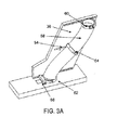
- Figures 3A and 3B show a third preferred embodiment of the feeding carriage of the present invention.
- the composition of the feeding carriage is substantially similar to that of the feeding carriage according to the second preferred embodiment of the present invention described above, with the difference that it further comprises an inner tube (58) which runs along the feeding carriage from its upper filling end to its lower discharging end.
- the inner tube (58) is intended for containing therein the particulate material.
- the inner tube (58) has a first clamp (60) at its upper end, a second clamp (62) at its lower end and an intermediate clamp (64).
- Each clamp (60, 62, 64) comprises at least one threaded hole for fixing same by means of nuts and bolts to the side plates (38) through the upper grooves (44), lower grooves (46) and intermediate grooves (54), respectively, in a plurality of positions.
- the feeding carriage is formed by a tube (58), preferably made of a flexible material which allows bending but is rigid enough to maintain the fixed position.
- Said tube (58) has fixing means which allow changing the entire feeding carriage geometry.
- Said fixing means can be a first clamp (60) at its upper end and a second clamp (62) at its lower end, although other equivalent fixing means are allowed, whereby fixing points which allow changing the entire feeding carriage geometry from its upper filling end to its lower discharging end are provided.
- said tube can be fixed to a side plate (38) having an upper groove (44) and a lower groove (46), where the tube can be fixed by means of clamps (60, 62).
- the feeding carriage can comprise an intermediate clamp (64) for providing another fixing point.
- the tube (58) can have a circular section, a square section or another suitable section type. At the same time, said section can remain constant or change along the path of the tube, as needed.
- the feeding carriage according to the present invention (shown by way of example according to the preferred embodiments thereof) therefore allows changing the inner geometry thereof (either at its lower end or along the entire inner path of the feeding carriage) for the purpose of finding an optimum geometry which minimizes the segregation effects for each specific particulate material that is being used. Tablets that are uniform in weight and composition are thereby obtained when compressing the particulate material in a mold (66) of the compressor machine.
- the present invention also discloses the use of a feeding carriage for a compressor machine such as any of those described above in the present document.
- Use according to the present invention comprises the steps of:
- the step of determining optimum carriage geometry can be performed empirically carrying out a series of tests until attaining said optimum geometry, or by means of computer simulation.
- the step of determining optimum carriage geometry comprises:
- the step of determining optimum carriage geometry comprises:
- the computer software preferably performs said simulation based on the discrete element method (DEM).
- DEM discrete element method
- DEM is used in the art for studying segregation phenomena. It is an effective method for addressing discontinuous and granular material engineering and is particularly useful for studying granular particle flows, powder mechanics and rock mechanics.
- the parameters which affect particulate material segregation in the feeding carriage and must be entered in the computer software to allow performing said simulation include, for example, the dimensions and density of the particulate material, as well as preferably also the coefficient of restitution, the coefficient of static friction and the coefficient of rolling friction between the particles of the particulate material and between the particulate material and feeding carriage.
- Component C1 consisted of cylinders 1.6 mm in diameter and 1.6 mm in height and with a density of 1104 kg/cm 3 .
- Component C2 consisted of cylinders 2.1 mm in diameter and 3.4 mm in height and with a density of 1021 kg/cm 3 .
- Figure 4 shows the four carriage geometries studied for determining optimum geometry for each of those mixtures. Reciprocating movement of an actual feeding carriage was reproduced in terms of movements, times, speeds and accelerations in all the simulations.
- the studied geometries were:
- RMSE root-mean-square error
- Table 1 shows the RMSE between the theoretical percentage of the reference component and the actual percentage of said reference component in the first 50 tablets.
- the RMSE therefore shows the degree of segregation occurring in the process, such that the lower the RMSE, the less the segregation that took place. Therefore, the values in bold indicate optimum carriage geometry.
- Table 1 Percentage of components Configuration Reference component (theoretical percentage) C1/C2 4V-120 2V-120 2H-150 0H-130 75/25 6.40 3.97 4.02 3.49 C2 (25%) 25/75 6.02 3.68 4.26 3.78 C1 (25%) 50/50 7.87 4.88 4.50 4.85 C1/C2 (50%)
- Table 2 shows the RMSE between the theoretical percentage of the reference component and the actual percentage of said reference component of tablet 20 to tablet 50. The values in bold indicate optimum carriage geometry.
- Table 2 Percentage of components Configuration Reference component (theoretical percentage) C1/C2 4V-120 2V-120 2H-150 0H-130 75/25 4.34 2.38 3.36 2.15 C2 (25%) 25/75 3.17 2.02 3.87 1.88 C1 (25%) 50/50 5.03 2.37 4.26 2.53 C1/C2 (50%)
- Tables 4, 5 and 6 below show the RMSE results obtained for each of the configurations studied for each of the feeding carriage configurations. Once again, values in bold indicate optimum carriage geometry for each case.
- Table 4 First embodiment of the feeding carriage Percentage of components Configuration Reference component (theoretical percentage) C1/C2 A B 15/85 5.822 6.293 C1 (15%) 85/15 6.401 5.433 C2 (15%) 50/50 8.818 7.024 C1 (50%)
- Table 5 Second embodiment of the feeding carriage Percentage of components Configuration Reference component (theoretical percentage) C1/C2 A B 15/85 7.718 4.178 C1 (15%) 85/15 6.648 8.586 C2 (15%) 50/50 6.138 7.626 C1 (50%)
- Table 6 Third embodiment of the feeding carriage Percentage of components Configuration Reference component (theoretical percentage) C1/C2 A B 15/85 2.471 3.911 C1 (15%) 85/15 5.293 5.277 C2 (15%) 50/50 4.339 6.022 C1 (50
- feeding carriages for compressor machines the geometry of which can be changed according to several configurations
- the invention is not limited to said embodiments and generally relates to a feeding carriage for a compressor machine of the type having an upper filling end through which a particulate material which is to be compressed in a mold of the compressor machine is introduced and a lower discharging end for discharging said particulate material towards said mold, provided that at least some of the elements forming said feeding carriage can move with respect to one another, which thereby allows modifying the geometry of at least one of said lower discharging end, said upper filling end and an intermediate portion of the feeding carriage located between both ends.
- the different elements forming the feeding carriage of the present invention can be any suitable material commonly used in the art, such as steel, for example.
- it can be manufactured from any suitable material, such as polyethylene, PVC, steel, etc.
- the feeding carriage of the present invention can have number markings, angle markings, etc., to help the user configure the different possible geometries thereof.
- the feeding carriage of the present invention can be applied to any suitable type of compressor machine, be it an eccentric machine or a rotary machine.
Landscapes
- Engineering & Computer Science (AREA)
- Mechanical Engineering (AREA)
- Robotics (AREA)
- Manufacturing & Machinery (AREA)
- Chemical & Material Sciences (AREA)
- Ceramic Engineering (AREA)
- Basic Packing Technique (AREA)
- Chutes (AREA)
- Feeding, Discharge, Calcimining, Fusing, And Gas-Generation Devices (AREA)
- Structures Of Non-Positive Displacement Pumps (AREA)
Abstract
Description
- The present invention generally relates to the field of compressor machines and more specifically to a feeding carriage for compressor machines.
- Compressor machines are widely used in different technical fields, such as, for example, in pharmacy, in the preparation of vitamins, compacted mechanical parts, microelectronics, etc. Compressor machines are used together with a feeding carriage, providing a mold of the compressor machine with the starting particulate material in which said particulate material is compressed for producing the final compressed article.
- Two main types of compressor machines are known: eccentric machines and rotary machines. Eccentric machines have a single mold, provided with one or more compression chambers and inserted in a part referred to as base plate. In such machines, the mold is fixed in place and the feeding carriage moves with a movement which allows filling the mold with particulate material, filling the mold completely, eliminating the remaining particulate material, and ejecting the final compressed article.
- Rotary compressor machines in turn have several molds and punches inserted in a circular movable base plate. In this case, the feeding carriage is fixed in place.
- When using compressor machines fed by means of a carriage or hopper, a phenomenon referred to as segregation occurs, causing non-homogenous filling of the mold of the compressor machine with particulate material. Obviously, this phenomenon is worsened when the particulate material is formed by a mixture of particles of different materials with different properties. This segregation phenomenon is particularly detrimental in applications in which it is important to maintain a specific proportion of the different materials used for manufacturing the final compressed article, such as in the pharmaceutical industry for tablet preparation.
- Furthermore, other detrimental circumstances can also occur such as compaction problems derived from the fact that some particles remain stuck to the walls and others do not, the possibility of the pills breaking when printing numbers, logos, etc., thereon.
- This segregation phenomenon, which consists of the clustering of similar particles, occurs by means of a combination of several mechanisms:
- a condensation mechanism that occurs due to the difference in density between different particles making up the particulate material: heavier particles tend to be located in the lower portion and lighter particles in the upper portion;
- a convection mechanism: this mechanism occurs in mixtures of particles having different sizes which, when subjected to certain vibration conditions, experience cyclic movement which causes them to accumulate in localized regions;
- segregation by percolation caused by small particles entering empty spaces generated by larger particles, in the direction of gravitational acceleration, until the granular structure tends to locally consist of the same particles; and
- a segregation trajectory through which the effects of friction reduce the speeds of smaller or more angular particles in a thin layer of moving material.
- The combination of one or more of the preceding mechanisms therefore causes the segregation or separation of different particles making up a starting particulate material as it moves from the feeding carriage to the mold of the compressor machine.
- A first segregation phenomenon can occur when filling the feeding carriage given that the particles fall at different speeds depending on their properties and also bounce off one another and the walls of the carriage in a different manner. Therefore, the properties of the particles (density, shape, size, etc.), the coefficients of friction (static and rolling) and the coefficient of restitution (in particle-particle and particle-carriage contacts), the carriage geometry, etc., affect this first segregation phenomenon.
- The continuous filling of the mold/molds also causes a segregation phenomenon, given that the particles move within the carriage at different speeds due to the aforementioned factors.
- In the case of eccentric compressor machines in which the feeding carriage is subjected to a continuous movement as mentioned above, this movement of the carriage causes an additional segregation of the particles present therein due to the previously mentioned factors.
- As mentioned above, the feeding carriage geometry influences said segregation phenomena. However, it is not possible to design a feeding carriage with a universal optimum geometry which reduces segregation phenomena since said segregation also depends on other factors such as the properties and proportions of the different particles making up the particulate material, etc.
- Patent document
US 6764296 discloses a fluidizing method for fluidizing the content of a feeding carriage in order to reduce these segregation phenomena. The particulate materials are passed through a fluidizer which is partitioned by means of a distributor plate to form first and second chambers. The particulate materials pass through said first chamber which is in gaseous communication with said second chamber by means of the porous distributor plate. Gas is delivered to the second chamber at a pressure sufficient to generate a gas bearing between the porous distributor plate and the particulate material. The gas is allowed to migrate through the particulate material, and then be vented to the surrounding atmosphere without causing substantial turbulence in the particulate material. - However, homogenization of the particulate material is hard to control by means of the method disclosed in patent document
US 6764296 , and therefore it is not possible to assure that the final compressed articles will have the necessary weight and composition uniformity. - Therefore, there is still a need in the art for a feeding carriage which allows reducing segregation phenomena occurring when manufacturing compressed articles, thereby obtaining an improvement in weight and composition uniformity of said compressed articles.
- The present invention solves the problems of the prior art by disclosing a feeding carriage for a compressor machine the geometry of which can be changed depending on the properties and proportions of the particles making up the starting particulate material, such that segregation phenomena occurring within said feeding carriage are minimized.
- Specifically, according to a first aspect the present invention discloses a feeding carriage for a compressor machine of the type having an upper filling end through which a particulate material which is to be compressed in a mold of the compressor machine is introduced and a lower discharging end for discharging said particulate material towards said mold. At least some of the elements forming the feeding carriage of the present invention can move with respect to one another, which thereby allows modifying the geometry of at least one of said lower discharging end, said upper filling end and an intermediate portion of the feeding carriage located between both ends. The term "move" must be interpreted in a broad sense, said term being able to refer to "modifying" the position of the elements of the carriage in order to modify the geometry thereof, "changing the diameter" of the carriage in order to modify the geometry thereof or "changing" the section of the carriage, among other equivalent concepts.
- According to a second aspect, the present invention discloses use of a feeding carriage for a compressor machine according to the first aspect of the present invention. The use according to the second aspect of the present invention comprises the steps of:
- determining optimum carriage geometry for a particulate material to be compressed;
- applying said optimum carriage geometry to the feeding carriage;
- filling the feeding carriage with the particulate material; and
- operating the compressor machine to manufacture the compressed articles.
- As will be described below in the present document, optimum carriage geometry can be determined by means of empirical tests or by means of computer simulation.
- The present invention will be better understood in reference to the following drawings illustrating preferred embodiments of the invention which are provided by way of example and must not be interpreted as limiting of the invention.
-
Figures 1A and1B show perspective views of a feeding carriage according to a first preferred embodiment of the present invention. -
Figures 2A and2B show perspective views of a feeding carriage according to a second preferred embodiment of the present invention. -
Figures 3A and3B show perspective views of a feeding carriage according to a third preferred embodiment of the present invention. -
Figure 4 shows side section views of a feeding carriage according to the first preferred embodiment of the invention in four different geometric configurations. -
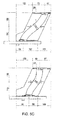
Figure 5A shows side section views of a feeding carriage according to the first preferred embodiment of the invention in two different geometric configurations. -
Figure 5B shows side section views of a feeding carriage according to the second preferred embodiment of the invention in two different geometric configurations. -
Figure 5C shows side section views of a feeding carriage according to the third preferred embodiment of the invention in two different geometric configurations. - As it is used throughout the present document and in the attached claims, the term "compressor machines" refers to machines used in any technical field for the preparation of compressed articles (pharmaceutical tablets, vitamins, parts for microelectronics, compacted structural parts, etc.) which can be fed with particulate material from a feeding carriage.
- As it is used throughout the present document and in the attached claims, the term "particulate material" refers to any type of material used for the preparation of articles compressed by means of compressor machines, regardless of the size and shape (cylindrical, spherical, etc.) thereof.
-
Figures 1A and1B show a feeding carriage according to a first preferred embodiment of the present invention. This feeding carriage is formed by two side plates (10), two rear plates (12A, 12B) and a fixed lower front plate (14). These elements will remain fixed firmly in place for all the configurable feeding carriage geometries. The rear plates (12A, 12B) and the fixed lower front plate (14) are attached to the side plates (10) in a conventional manner by means of nuts and bolts. However, the person skilled in the art will understand that other attachment means such as welding, adhesives, etc., can be used. - In order to change its geometry, the feeding carriage further comprises a movable upper front plate (16), a first sliding front plate (18) and a second sliding front plate (20).
- The upper front plate (16) can be fixed to both side plates (10) by means of nuts and bolts (22) in a plurality of positions. To that end, as can be seen in
Figure 1A , the upper front plate (16) has a plurality of threaded holes (24). In turn, as seen inFigure 1B , the side plates (10) have a pair of grooves (26). The nuts and bolts are introduced through the grooves (26) into the threaded holes (24) for fixing the upper front plate (16) to the side plates (10) in the desired position. - The first sliding front plate (18) is in turn attached to the upper front plate (16) by means of a hinge (28) which allows changing the angle of inclination formed between both, thereby providing one more degree of freedom for changing the feeding carriage geometry.
- The first sliding front plate (18) is attached to the second sliding front plate (20) by means of nuts and bolts (22) through a threaded hole (30) present in the second sliding front plate (20) and a groove (32) present in the first sliding front plate (18), said groove (32) allowing relative sliding of one sliding front plate with respect to the other. According to the preferred embodiment, the second sliding front plate (20) has a plurality of threaded holes (30), such that the first sliding front plate (18) and the second sliding front plate (20) can be fixed to one another in a plurality of positions by means of nuts and bolts (22) through the groove (32) and any one of the plurality of threaded holes (30).
- Finally, the second sliding front plate (20) can be fixed to both side plates (10) by means of nuts and bolts (22) in a plurality of positions. To that end, the second sliding front plate (20) has a threaded hole (34) arranged to coincide with one of the plurality of holes (36) present in the side plates (10). Therefore, as will be described below in the present document, depending on which of the plurality of holes (36) of the side plates (10) in which the threaded hole (34) of the second sliding front plate (20) is fixed, the feeding carriage will have a different geometry that will influence segregation phenomena experienced by the particulate material therein.
- According to the embodiment shown in
Figures 1A and1B , the second sliding front plate (20) can be fixed to the side plates (10) in eight different geometric configurations, whereby providing a wide choice for the feeding carriage geometry in order to reduce segregation phenomena occurring to the minimum. Obviously, the person skilled in the art will understand that this embodiment is not limiting and that other feeding carriages according to the present invention with a greater or smaller number of possible geometric configurations can be designed. - The attached
Figures 2A and2B show a second preferred embodiment of the feeding carriage of the present invention. According to this second embodiment, the feeding carriage is formed by two side plates (38), a front plate (40) and a rear plate (42). Each side plate (38) has an upper groove (44) and a lower groove (46). The front plate (40) and the rear plate (42) each have a lower threaded fixing hole (48) and a plurality of upper threaded fixing holes (50) for fixing said front plate (40) and rear plate (42) to the side plates (38) in a plurality of positions by means of nuts and bolts (52) through the lower grooves (46) and upper grooves (44), respectively. - The feeding carriage according to this second preferred embodiment of the invention therefore allows changing the entire carriage geometry from its upper filling end to its lower discharging end.
- As can be seen in
Figure 2A , the side walls (38) also comprise an intermediate groove (54) the function of which is to adapt the feeding carriage for use according to a third preferred embodiment of the present invention described below in the present document. Given that said intermediate groove (54) is not of use according to this second preferred embodiment of the present invention, it is covered with a cover (56) to prevent the particulate material from leaking out through said intermediate groove (54). -
Figures 3A and3B show a third preferred embodiment of the feeding carriage of the present invention. In this case, the composition of the feeding carriage is substantially similar to that of the feeding carriage according to the second preferred embodiment of the present invention described above, with the difference that it further comprises an inner tube (58) which runs along the feeding carriage from its upper filling end to its lower discharging end. The inner tube (58) is intended for containing therein the particulate material. The inner tube (58) has a first clamp (60) at its upper end, a second clamp (62) at its lower end and an intermediate clamp (64). Each clamp (60, 62, 64) comprises at least one threaded hole for fixing same by means of nuts and bolts to the side plates (38) through the upper grooves (44), lower grooves (46) and intermediate grooves (54), respectively, in a plurality of positions. - According to another embodiment of the present invention, the feeding carriage is formed by a tube (58), preferably made of a flexible material which allows bending but is rigid enough to maintain the fixed position. Said tube (58) has fixing means which allow changing the entire feeding carriage geometry. Said fixing means can be a first clamp (60) at its upper end and a second clamp (62) at its lower end, although other equivalent fixing means are allowed, whereby fixing points which allow changing the entire feeding carriage geometry from its upper filling end to its lower discharging end are provided. To fix the tube and to enable determining its geometry by means of the parameters indicated in the present specification, said tube can be fixed to a side plate (38) having an upper groove (44) and a lower groove (46), where the tube can be fixed by means of clamps (60, 62). The feeding carriage can comprise an intermediate clamp (64) for providing another fixing point.
- The person skilled in the art will understand that the tube (58) can have a circular section, a square section or another suitable section type. At the same time, said section can remain constant or change along the path of the tube, as needed.
- The feeding carriage according to the present invention (shown by way of example according to the preferred embodiments thereof) therefore allows changing the inner geometry thereof (either at its lower end or along the entire inner path of the feeding carriage) for the purpose of finding an optimum geometry which minimizes the segregation effects for each specific particulate material that is being used. Tablets that are uniform in weight and composition are thereby obtained when compressing the particulate material in a mold (66) of the compressor machine.
- The present invention also discloses the use of a feeding carriage for a compressor machine such as any of those described above in the present document. Use according to the present invention comprises the steps of:
- determining optimum carriage geometry for a particulate material to be compressed;
- applying said optimum carriage geometry to the feeding carriage;
- filling the feeding carriage with the particulate material; and
- operating the compressor machine to manufacture the compressed articles.
- The step of determining optimum carriage geometry can be performed empirically carrying out a series of tests until attaining said optimum geometry, or by means of computer simulation. Specifically, according to a preferred embodiment of the present invention the step of determining optimum carriage geometry comprises:
- a) applying a first geometry to the feeding carriage;
- b) manufacturing compressed articles with said first geometry;
- c) analyzing the composition of the compressed articles;
- d) repeating steps a)-c) for a plurality of different carriage geometries; and
- e) determining the optimum geometry for the particulate material used from among the plurality of geometries applied to the feeding carriage.
- According to a second preferred embodiment of the present invention, the step of determining optimum carriage geometry comprises:
- a) entering parameters affecting particulate material segregation in the feeding carriage in computer software;
- b) performing particulate material segregation simulations with different feeding carriage geometries by means of said computer software; and
- c) determining the optimum geometry for the particulate material used from among the plurality of geometries simulated for the feeding carriage.
- The computer software preferably performs said simulation based on the discrete element method (DEM). DEM is used in the art for studying segregation phenomena. It is an effective method for addressing discontinuous and granular material engineering and is particularly useful for studying granular particle flows, powder mechanics and rock mechanics.
- The parameters which affect particulate material segregation in the feeding carriage and must be entered in the computer software to allow performing said simulation include, for example, the dimensions and density of the particulate material, as well as preferably also the coefficient of restitution, the coefficient of static friction and the coefficient of rolling friction between the particles of the particulate material and between the particulate material and feeding carriage.
- Two illustrative and non-limiting examples of determining optimum carriage geometry for a feeding carriage according to the present invention are described below.
- In this first example, mixtures with two components, C1 and C2, were studied. Component C1 consisted of cylinders 1.6 mm in diameter and 1.6 mm in height and with a density of 1104 kg/cm3. Component C2 consisted of cylinders 2.1 mm in diameter and 3.4 mm in height and with a density of 1021 kg/cm3. Three mixtures of these components C1/C2 at 75%/25%, 25%/75% and 50%/50% were studied.
-
Figure 4 shows the four carriage geometries studied for determining optimum geometry for each of those mixtures. Reciprocating movement of an actual feeding carriage was reproduced in terms of movements, times, speeds and accelerations in all the simulations. The studied geometries were: - 4V-120: The second sliding front plate fixed to vertical hole 4 of the side plates. The first sliding front plate and the upper front plate form an angle of 120°.
- 2V-120: The second sliding front plate fixed to vertical hole 2 of the side plates. The first sliding front plate and the upper front plate form an angle of 120°.
- 2H-150: The second sliding front plate fixed to horizontal hole 2 of the side plates. The first sliding front plate and the upper front plate form an angle of 150°.
- 0H-130: The second sliding front plate fixed to hole 0 (corner hole) of the side plates. The first sliding front plate and the upper front plate form an angle of 130°.
- The root-mean-square error (RMSE) corresponding, on one hand, to the first 50 tablets obtained and, on the other hand, to tablets 20-50 obtained in the so-called rated operating condition, was determined for each simulation. In fact, a first segregation phenomenon affecting approximately the first 20 tablets occurs when filling the non-operating feeding carriage. Tablets 20-50 are only affected by the actual segregation of the reciprocating movement of the feeding carriage.
- Table 1 below shows the RMSE between the theoretical percentage of the reference component and the actual percentage of said reference component in the first 50 tablets. The RMSE therefore shows the degree of segregation occurring in the process, such that the lower the RMSE, the less the segregation that took place. Therefore, the values in bold indicate optimum carriage geometry.
Table 1 Percentage of components Configuration Reference component (theoretical percentage) C1/ C2 4V-120 2V-120 2H-150 0H-130 75/25 6.40 3.97 4.02 3.49 C2 (25%) 25/75 6.02 3.68 4.26 3.78 C1 (25%) 50/50 7.87 4.88 4.50 4.85 C1/C2 (50%) - Table 2 below shows the RMSE between the theoretical percentage of the reference component and the actual percentage of said reference component of
tablet 20 totablet 50. The values in bold indicate optimum carriage geometry.Table 2 Percentage of components Configuration Reference component (theoretical percentage) C1/ C2 4V-120 2V-120 2H-150 0H-130 75/25 4.34 2.38 3.36 2.15 C2 (25%) 25/75 3.17 2.02 3.87 1.88 C1 (25%) 50/50 5.03 2.37 4.26 2.53 C1/C2 (50%) - As can be seen from the preceding tables, optimum carriage configuration changes with the proportion of the different particles making up the particulate material used as raw material. Therefore, there is a proven need for a carriage having a variable geometry such as the one disclosed in a novel manner by the present invention which is adaptable and can provide optimum configuration for each composition of different particulate material used as raw material.
- Simulations similar to those in Example 1 were performed by means of the discrete element method. In this case, the particles making up the particulate material were:
- Component C1: Spheres 2 mm in diameter and with a density of 1150 kg/cm3.
- Component C2: Spheres 4 mm in diameter and with a density of 1150 kg/cm3.
- In this case, other additional parameters also affecting segregation phenomena occurring inside the feeding carriage were also taken into account in the computer simulation. These parameters are summarized in Table 3 below:
Table 3 C1 C2 Coefficient of restitution Particle-carriage 0.2 0.2 Particle-particle 0.7 0.7 Coefficient of static friction Particle-carriage 0.5 0.5 Particle-particle 0.5 0.5 Coefficient of rolling friction Particle-carriage 0 0 Particle-particle 0.5 0.5 - Three different proportions of components C1/C2 at 15%/85%, 85%/15% and 50%/50% were studied in two different geometries of each of the three preferred embodiments of the feeding carriage of the present invention described above in the present document (
Figures 1A ,1 B; 2A, 2B; and 3A, 3B, respectively). - The attached
Figures 5A ,5B and5C each show the two studied feeding carriage configurations according to several preferred embodiments of the present invention. The dimensions included in said drawings constitute the exact geometric arrangements under study. - Tables 4, 5 and 6 below show the RMSE results obtained for each of the configurations studied for each of the feeding carriage configurations. Once again, values in bold indicate optimum carriage geometry for each case.
Table 4: First embodiment of the feeding carriage Percentage of components Configuration Reference component (theoretical percentage) C1/C2 A B 15/85 5.822 6.293 C1 (15%) 85/15 6.401 5.433 C2 (15%) 50/50 8.818 7.024 C1 (50%) Table 5: Second embodiment of the feeding carriage Percentage of components Configuration Reference component (theoretical percentage) C1/C2 A B 15/85 7.718 4.178 C1 (15%) 85/15 6.648 8.586 C2 (15%) 50/50 6.138 7.626 C1 (50%) Table 6: Third embodiment of the feeding carriage Percentage of components Configuration Reference component (theoretical percentage) C1/C2 A B 15/85 2.471 3.911 C1 (15%) 85/15 5.293 5.277 C2 (15%) 50/50 4.339 6.022 C1 (50%) - Although the present invention has been described in reference to several preferred embodiments thereof, the person skilled in the art will understand that modifications and variations can be applied thereto without departing from the essence and scope of the present invention.
- For example, although several embodiments of feeding carriages for compressor machines the geometry of which can be changed according to several configurations have been described, it must be understood that the invention is not limited to said embodiments and generally relates to a feeding carriage for a compressor machine of the type having an upper filling end through which a particulate material which is to be compressed in a mold of the compressor machine is introduced and a lower discharging end for discharging said particulate material towards said mold, provided that at least some of the elements forming said feeding carriage can move with respect to one another, which thereby allows modifying the geometry of at least one of said lower discharging end, said upper filling end and an intermediate portion of the feeding carriage located between both ends. In practice, being able to define all the geometric parameters of the carriage which can have different shape variations (regardless of its shape, it is possible to determine/calculate its geometry) and being able to define the different parameters of the actual mixture to be compressed and other mechanical parameters of the process enable determining said optimum carriage geometry by means of software or by empirical means, which significantly reduces the segregation effect of the compressed material. Once the optimum geometry is determined, the carriage is suitably configured according to the determined data.
- Likewise, although a feeding carriage according to the first preferred embodiment of the invention having two rear plates has been described, it must be understood that additional embodiments of said feeding carriage can have a single rear plate, or more than two rear plates, without departing from the scope of the invention.
- Similarly, although a feeding carriage according to the third preferred embodiment of the invention having an intermediate groove and an intermediate clamp has been described, it must be understood that other embodiments of the feeding carriage may lack said intermediate groove and intermediate clamp.
- The different elements forming the feeding carriage of the present invention can be any suitable material commonly used in the art, such as steel, for example. In the case of comprising an inner tube, it can be manufactured from any suitable material, such as polyethylene, PVC, steel, etc.
- The feeding carriage of the present invention can have number markings, angle markings, etc., to help the user configure the different possible geometries thereof.
- The feeding carriage of the present invention can be applied to any suitable type of compressor machine, be it an eccentric machine or a rotary machine.
Claims (15)
- A feeding carriage for a compressor machine of the type having an upper filling end through which a particulate material which is to be compressed in a mold of the compressor machine is introduced and a lower discharging end for discharging said particulate material towards said mold, characterized in that at least some of the elements forming said feeding carriage can move with respect to one another, which thereby allows modifying the geometry of at least one of said lower discharging end, said upper filling end and an intermediate portion of the feeding carriage located between both ends.
- The feeding carriage according to claim 1, characterized in that it is formed by two side plates (10), at least one rear plate (12A, 12B), a fixed lower front plate (14), a movable upper front plate (16), a first sliding front plate (18) and a second sliding front plate (20) which allow changing the feeding carriage geometry.
- The feeding carriage according to claim 2, characterized in that:- the upper front plate (16) can be fixed to each side plate (10) in a plurality of positions by means of nuts and bolts (22) through a plurality of threaded holes (24) in the upper front plate (16) and a plurality of corresponding grooves (26) in each side plate (10);- the first sliding front plate (18) is attached to the upper front plate (16) by means of a hinge (28) which allows changing the angle of inclination formed between both;- the first sliding front plate (18) is attached to the second sliding front plate (20) by means of nuts and bolts (22) through a threaded hole (30) present in one of the first or second sliding front plates and a groove (32) present in the other one of the second or first sliding front plates, said groove (32) allowing relative sliding of one sliding front plate with respect to the other;- the second sliding front plate (20) can be fixed to each side plate (10) in a plurality of positions by means of nuts and bolts (22) through a threaded hole (34) in the second sliding front plate (20) and one of a plurality of holes (36) in each side plate (10);whereby the different possible fixing positions of the upper front plate (16), the first sliding front plate (18) and the second sliding front plate (20) allow changing the geometry of the lower discharging end of the feeding carriage.
- The feeding carriage according to any of claims 2 or 3, characterized in that the first sliding front plate (18) has a groove (32) and the second sliding front plate (20) has a plurality of threaded holes (30) allowing the fixing of the first sliding front plate (18) and the second sliding front plate (20) by means of nuts and bolts (22) through any one of said plurality of threaded holes (30) and the groove (32) in a plurality of positions.
- The feeding carriage according to claim 1, characterized in that it is formed by two side plates (38), a movable front plate (40) and a movable rear plate (42), whereby it allows changing the feeding carriage geometry from its upper filling end to its lower discharging end.
- The feeding carriage according to claim 5, characterized in that the side plates (38) have an upper groove (44) and a lower groove (46), the front and rear plates (40, 42) have a lower threaded fixing hole (48) and a plurality of upper threaded fixing holes (50) for fixing said front plate (40) and rear plate (42) to the side plates (38) in a plurality of positions by means of nuts and bolts (52) through the lower grooves (46) and upper grooves (44), respectively, whereby it allows changing the feeding carriage geometry from its upper filling end to its lower discharging end.
- The feeding carriage according to any of claims 5 or 6, characterized in that it further comprises an inner tube (58) running along the feeding carriage from its upper filling end to its lower discharging end and intended for containing therein the particulate material, the inner tube (58) having a first clamp (60) at its upper end and a second clamp (62) at its lower end, each clamp (60, 62) having at least one threaded hole for fixing thereof by means of nuts and bolts to the side plates (38) through the upper grooves (44) and lower grooves (46) in a plurality of positions.
- The feeding carriage according to claim 7, characterized in that each of the side walls (38) further comprises an intermediate groove (54) between the upper groove (44) and the lower groove (46), and the inner tube (58) further comprises an intermediate clamp (64) with at least one threaded fixing hole for fixing thereof by means of nuts and bolts to the side plates (38) through the intermediate grooves (54).
- The feeding carriage according to claim 1, characterized in that it is formed by a tube (58), said tube (58) having a first clamp (60) at its upper end and a second clamp (62) at its lower end whereby fixing points which allow changing the feeding carriage geometry from its upper filling end to its lower discharging end are provided.
- The feeding carriage according to claim 9, characterized in that it comprises an intermediate clamp (64) for providing another fixing point.
- Use of a feeding carriage for a compressor machine according to any of the preceding claims, characterized in that it comprises the steps of:- determining optimum carriage geometry for a particulate material to be compressed;- applying said optimum carriage geometry to the feeding carriage;- filling the feeding carriage with the particulate material; and- operating the compressor machine to manufacture the compressed articles.
- Use according to claim 11, characterized in that the step of determining optimum carriage geometry comprises:a) applying a first geometry to the feeding carriage;b) manufacturing compressed articles with said first geometry;c) analyzing the composition of the compressed articles;d) repeating steps a)-c) for a plurality of different carriage geometries; ande) determining the optimum geometry for the particulate material used from among the plurality of geometries applied to the feeding carriage.
- Use according to claim 11, characterized in that the step of determining optimum carriage geometry comprises:a) entering parameters affecting particulate material segregation in the feeding carriage in computer software;b) performing particulate material segregation simulations with different feeding carriage geometries by means of said computer software; andc) determining the optimum geometry for the particulate material used from among the plurality of geometries simulated for the feeding carriage.
- Use according to claim 13, characterized in that the parameters affecting particulate material segregation in the feeding carriage include the dimensions and density of the particulate material.
- Use according to claim 14, characterized in that the parameters affecting particulate material segregation in the feeding carriage furthermore include the coefficient of restitution, the coefficient of static friction and the coefficient of rolling friction between the particles of the particulate material and between the particulate material and the feeding carriage.
Applications Claiming Priority (2)
| Application Number | Priority Date | Filing Date | Title |
|---|---|---|---|
| ES201300551A ES2424568B2 (en) | 2013-06-04 | 2013-06-04 | Feeder car for compressor machine and its use |
| PCT/ES2014/000086 WO2014195536A1 (en) | 2013-06-04 | 2014-05-21 | Feeding carriage for compressor machine and use of same |
Publications (3)
| Publication Number | Publication Date |
|---|---|
| EP2949440A1 true EP2949440A1 (en) | 2015-12-02 |
| EP2949440A4 EP2949440A4 (en) | 2016-11-16 |
| EP2949440B1 EP2949440B1 (en) | 2020-08-19 |
Family
ID=49182564
Family Applications (1)
| Application Number | Title | Priority Date | Filing Date |
|---|---|---|---|
| EP14807935.3A Not-in-force EP2949440B1 (en) | 2013-06-04 | 2014-05-21 | Feeding carriage for compressor machine and use of same |
Country Status (5)
| Country | Link |
|---|---|
| US (1) | US10322557B2 (en) |
| EP (1) | EP2949440B1 (en) |
| JP (1) | JP5976962B2 (en) |
| ES (1) | ES2424568B2 (en) |
| WO (1) | WO2014195536A1 (en) |
Family Cites Families (29)
| Publication number | Priority date | Publication date | Assignee | Title |
|---|---|---|---|---|
| GB136302A (en) * | 1918-12-21 | 1919-12-18 | Samuel Walter Wilkinson | Improvements in or relating to Machines for Making Compressed Tablets and the like. |
| US1452381A (en) * | 1921-02-16 | 1923-04-17 | Walter S Hildebrand | Means for filling molds |
| GB227996A (en) * | 1924-01-12 | 1925-01-29 | Drakes Ltd | Improvements in apparatus for measuring by volume and delivering coal and like granulated substances |
| US2674008A (en) * | 1951-04-11 | 1954-04-06 | Norton Co | Molding mechanism |
| US2839787A (en) * | 1954-07-19 | 1958-06-24 | Western Electric Co | Apparatus for molding powdered granular material into preformed articles |
| US2970554A (en) * | 1959-01-09 | 1961-02-07 | Bristol Myers Co | Tablet press |
| DE2242245C3 (en) * | 1972-08-28 | 1975-10-23 | Max Roth Kg, 7560 Gaggenau | Slip paver |
| US4108338A (en) * | 1977-08-15 | 1978-08-22 | Pennwalt Corporation | Rotary tabletting press with powder feed adjustment valve |
| US4274527A (en) * | 1977-09-27 | 1981-06-23 | Baker John H | Apparatus and method for uniformly spreading a flowing stream of dry solids |
| JPS5620000A (en) * | 1979-07-26 | 1981-02-25 | Mitsui Kinzoku Kyushu Kiko Kk | Turning press |
| JPS6195800A (en) * | 1984-10-17 | 1986-05-14 | Matsushita Electric Ind Co Ltd | powder molding machine |
| CH670439A5 (en) * | 1986-09-03 | 1989-06-15 | Hans Brehm | |
| US4813818A (en) * | 1987-08-25 | 1989-03-21 | Michael Sanzone | Apparatus and method for feeding powdered materials |
| WO1989002866A1 (en) * | 1987-09-30 | 1989-04-06 | Mitsui Toatsu Chemicals, Incorporated | Apparatus for preventing segregation of particulate bodies |
| JPH0243594Y2 (en) * | 1987-11-25 | 1990-11-20 | ||
| JP3063499B2 (en) * | 1993-12-13 | 2000-07-12 | 住友電気工業株式会社 | Manufacturing method of powder compact for sintered parts |
| US6402500B1 (en) | 1997-11-06 | 2002-06-11 | Matsys | Fluidized fillshoe system |
| DE19851527A1 (en) * | 1998-11-09 | 2000-05-11 | Dorst Masch & Anlagen | Filling device for axial powder presses |
| CN1266303C (en) * | 2000-04-21 | 2006-07-26 | 株式会社新王磁材 | Equipment for pressing powder material, and method for producing rare-earth magnetic using said equipment |
| ITBO20010141A1 (en) | 2001-03-16 | 2002-09-16 | Ima Spa | COMPRESSING MACHINE FOR THE PRODUCTION OF TABLETS |
| ITTV20020131A1 (en) * | 2002-10-31 | 2004-05-01 | Luca Toncelli | DISPENSER OF STONE MIXTURES OR AGGLOMERATED CERAMIC FOR FILLING A MOLD |
| JP4325955B2 (en) * | 2003-11-14 | 2009-09-02 | 澁谷工業株式会社 | Granular material supply device |
| US20080259721A1 (en) | 2003-12-17 | 2008-10-23 | Mova Pharmaceutical Corporation | Hopper with Flow Controller/Enhancer for Controlling the Gravitational Flow of Granular Material |
| GB0526383D0 (en) * | 2005-12-23 | 2006-02-08 | Univ Greenwich | Controlling bulk particulate flow rates |
| ES2326511B2 (en) | 2008-04-10 | 2010-02-18 | Universidad De La Rioja | DEVICE FOR COMPRESSION OF POWDER FOOD ADDITIVES. |
| FI122497B (en) * | 2010-06-15 | 2012-02-29 | Elematic Group Oy | Method and apparatus for casting a concrete product |
| MX336338B (en) | 2010-11-18 | 2016-01-15 | Cavadistrib Inc | Automated feeding apparatus. |
| CN202088501U (en) | 2011-04-27 | 2011-12-28 | 聊城万合工业制造有限公司 | Direct-connection type single-punch tablet press capable of realizing online adjustment of material filling |
| CN202319013U (en) | 2011-11-17 | 2012-07-11 | 成都苑东药业有限公司 | Material charging and tablet pressing device of single-punch tablet press capable of controlling output raw material |
-
2013
- 2013-06-04 ES ES201300551A patent/ES2424568B2/en active Active
-
2014
- 2014-05-21 JP JP2015558512A patent/JP5976962B2/en not_active Expired - Fee Related
- 2014-05-21 EP EP14807935.3A patent/EP2949440B1/en not_active Not-in-force
- 2014-05-21 US US14/892,313 patent/US10322557B2/en active Active
- 2014-05-21 WO PCT/ES2014/000086 patent/WO2014195536A1/en not_active Ceased
Also Published As
| Publication number | Publication date |
|---|---|
| WO2014195536A1 (en) | 2014-12-11 |
| US20160114549A1 (en) | 2016-04-28 |
| JP2016511153A (en) | 2016-04-14 |
| JP5976962B2 (en) | 2016-08-24 |
| ES2424568A1 (en) | 2013-10-04 |
| EP2949440A4 (en) | 2016-11-16 |
| ES2424568B2 (en) | 2014-04-28 |
| US10322557B2 (en) | 2019-06-18 |
| EP2949440B1 (en) | 2020-08-19 |
Similar Documents
| Publication | Publication Date | Title |
|---|---|---|
| RU2656902C2 (en) | Method for continuous production of tablets, tabletting system for carrying out the method, and use of the tabletting system for the production of tablets of at least two ingredients containing particles with a significant difference in particle size | |
| CN102260790B (en) | Method for production of carbon composite metal oxide briquette | |
| US11717909B2 (en) | Powder feeding device and additive manufacturing device | |
| KR20140073557A (en) | Powder filling device with redundant powder collection mechanism, and rotary compression molding machine | |
| JP4727588B2 (en) | Device for filling the mold with powder or with mixed powder | |
| CN105083601B (en) | Medicine feeding apparatus | |
| US10322557B2 (en) | Feeding carriage for compressor machine and use of same | |
| US6772801B1 (en) | Fluidization of particles for encapsulation in oral dosage pharmaceutical products | |
| JP6912586B2 (en) | Manufacturing method of titanium or titanium alloy green compact | |
| BR0307215A (en) | Method and apparatus for the production of multilevel components by shock compression of powder material | |
| EP2127630B1 (en) | Transfer board | |
| US12594736B2 (en) | Additive manufacturing method and apparatus for individualized polypill capsules using micro-dosed and compacted powders | |
| EP2119556B1 (en) | Compression tableting machine | |
| US12389922B2 (en) | Method for producing compressed body of powder | |
| RU2713254C1 (en) | Method of making articles from metal powders | |
| ES2939251T3 (en) | Method for pressing ceramic tiles | |
| JP6529880B2 (en) | Rotary powder compression molding apparatus and multistage rotary powder compression molding apparatus | |
| JP2009279624A (en) | Powder feed auxiliary tool and powder feed device using the same | |
| RU2491153C1 (en) | Method of producing articles from composite powders | |
| KR102318083B1 (en) | Molding apparatus of briquette for deoxidizer using aluminum by-product contained chip | |
| El Hebieshy | Die filling of aerated powders. | |
| JP4507256B2 (en) | Rotary powder compaction molding machine | |
| CN104001920B (en) | A kind of powder metallurgy preparation system of cylindrical parts | |
| CN102218020B (en) | Capsule pill feeding mechanism | |
| JP2003514668A (en) | Method and apparatus for producing light metal pellets |
Legal Events
| Date | Code | Title | Description |
|---|---|---|---|
| PUAI | Public reference made under article 153(3) epc to a published international application that has entered the european phase |
Free format text: ORIGINAL CODE: 0009012 |
|
| 17P | Request for examination filed |
Effective date: 20150824 |
|
| AK | Designated contracting states |
Kind code of ref document: A1 Designated state(s): AL AT BE BG CH CY CZ DE DK EE ES FI FR GB GR HR HU IE IS IT LI LT LU LV MC MK MT NL NO PL PT RO RS SE SI SK SM TR |
|
| AX | Request for extension of the european patent |
Extension state: BA ME |
|
| DAX | Request for extension of the european patent (deleted) | ||
| A4 | Supplementary search report drawn up and despatched |
Effective date: 20161013 |
|
| RIC1 | Information provided on ipc code assigned before grant |
Ipc: B65G 11/10 20060101ALI20161007BHEP Ipc: B65G 47/18 20060101ALI20161007BHEP Ipc: B28B 13/02 20060101AFI20161007BHEP Ipc: B30B 15/30 20060101ALI20161007BHEP Ipc: B29C 31/04 20060101ALI20161007BHEP Ipc: B65G 47/44 20060101ALI20161007BHEP |
|
| GRAP | Despatch of communication of intention to grant a patent |
Free format text: ORIGINAL CODE: EPIDOSNIGR1 |
|
| STAA | Information on the status of an ep patent application or granted ep patent |
Free format text: STATUS: GRANT OF PATENT IS INTENDED |
|
| INTG | Intention to grant announced |
Effective date: 20200430 |
|
| GRAS | Grant fee paid |
Free format text: ORIGINAL CODE: EPIDOSNIGR3 |
|
| GRAA | (expected) grant |
Free format text: ORIGINAL CODE: 0009210 |
|
| STAA | Information on the status of an ep patent application or granted ep patent |
Free format text: STATUS: THE PATENT HAS BEEN GRANTED |
|
| AK | Designated contracting states |
Kind code of ref document: B1 Designated state(s): AL AT BE BG CH CY CZ DE DK EE ES FI FR GB GR HR HU IE IS IT LI LT LU LV MC MK MT NL NO PL PT RO RS SE SI SK SM TR |
|
| REG | Reference to a national code |
Ref country code: CH Ref legal event code: EP |
|
| REG | Reference to a national code |
Ref country code: DE Ref legal event code: R096 Ref document number: 602014069216 Country of ref document: DE |
|
| REG | Reference to a national code |
Ref country code: AT Ref legal event code: REF Ref document number: 1303421 Country of ref document: AT Kind code of ref document: T Effective date: 20200915 |
|
| REG | Reference to a national code |
Ref country code: IE Ref legal event code: FG4D |
|
| REG | Reference to a national code |
Ref country code: LT Ref legal event code: MG4D |
|
| REG | Reference to a national code |
Ref country code: NL Ref legal event code: MP Effective date: 20200819 |
|
| PG25 | Lapsed in a contracting state [announced via postgrant information from national office to epo] |
Ref country code: HR Free format text: LAPSE BECAUSE OF FAILURE TO SUBMIT A TRANSLATION OF THE DESCRIPTION OR TO PAY THE FEE WITHIN THE PRESCRIBED TIME-LIMIT Effective date: 20200819 Ref country code: LT Free format text: LAPSE BECAUSE OF FAILURE TO SUBMIT A TRANSLATION OF THE DESCRIPTION OR TO PAY THE FEE WITHIN THE PRESCRIBED TIME-LIMIT Effective date: 20200819 Ref country code: SE Free format text: LAPSE BECAUSE OF FAILURE TO SUBMIT A TRANSLATION OF THE DESCRIPTION OR TO PAY THE FEE WITHIN THE PRESCRIBED TIME-LIMIT Effective date: 20200819 Ref country code: BG Free format text: LAPSE BECAUSE OF FAILURE TO SUBMIT A TRANSLATION OF THE DESCRIPTION OR TO PAY THE FEE WITHIN THE PRESCRIBED TIME-LIMIT Effective date: 20201119 Ref country code: PT Free format text: LAPSE BECAUSE OF FAILURE TO SUBMIT A TRANSLATION OF THE DESCRIPTION OR TO PAY THE FEE WITHIN THE PRESCRIBED TIME-LIMIT Effective date: 20201221 Ref country code: NO Free format text: LAPSE BECAUSE OF FAILURE TO SUBMIT A TRANSLATION OF THE DESCRIPTION OR TO PAY THE FEE WITHIN THE PRESCRIBED TIME-LIMIT Effective date: 20201119 Ref country code: GR Free format text: LAPSE BECAUSE OF FAILURE TO SUBMIT A TRANSLATION OF THE DESCRIPTION OR TO PAY THE FEE WITHIN THE PRESCRIBED TIME-LIMIT Effective date: 20201120 Ref country code: FI Free format text: LAPSE BECAUSE OF FAILURE TO SUBMIT A TRANSLATION OF THE DESCRIPTION OR TO PAY THE FEE WITHIN THE PRESCRIBED TIME-LIMIT Effective date: 20200819 |
|
| REG | Reference to a national code |
Ref country code: AT Ref legal event code: MK05 Ref document number: 1303421 Country of ref document: AT Kind code of ref document: T Effective date: 20200819 |
|
| PG25 | Lapsed in a contracting state [announced via postgrant information from national office to epo] |
Ref country code: IS Free format text: LAPSE BECAUSE OF FAILURE TO SUBMIT A TRANSLATION OF THE DESCRIPTION OR TO PAY THE FEE WITHIN THE PRESCRIBED TIME-LIMIT Effective date: 20201219 Ref country code: LV Free format text: LAPSE BECAUSE OF FAILURE TO SUBMIT A TRANSLATION OF THE DESCRIPTION OR TO PAY THE FEE WITHIN THE PRESCRIBED TIME-LIMIT Effective date: 20200819 Ref country code: NL Free format text: LAPSE BECAUSE OF FAILURE TO SUBMIT A TRANSLATION OF THE DESCRIPTION OR TO PAY THE FEE WITHIN THE PRESCRIBED TIME-LIMIT Effective date: 20200819 Ref country code: RS Free format text: LAPSE BECAUSE OF FAILURE TO SUBMIT A TRANSLATION OF THE DESCRIPTION OR TO PAY THE FEE WITHIN THE PRESCRIBED TIME-LIMIT Effective date: 20200819 Ref country code: PL Free format text: LAPSE BECAUSE OF FAILURE TO SUBMIT A TRANSLATION OF THE DESCRIPTION OR TO PAY THE FEE WITHIN THE PRESCRIBED TIME-LIMIT Effective date: 20200819 |
|
| PG25 | Lapsed in a contracting state [announced via postgrant information from national office to epo] |
Ref country code: SM Free format text: LAPSE BECAUSE OF FAILURE TO SUBMIT A TRANSLATION OF THE DESCRIPTION OR TO PAY THE FEE WITHIN THE PRESCRIBED TIME-LIMIT Effective date: 20200819 Ref country code: RO Free format text: LAPSE BECAUSE OF FAILURE TO SUBMIT A TRANSLATION OF THE DESCRIPTION OR TO PAY THE FEE WITHIN THE PRESCRIBED TIME-LIMIT Effective date: 20200819 Ref country code: EE Free format text: LAPSE BECAUSE OF FAILURE TO SUBMIT A TRANSLATION OF THE DESCRIPTION OR TO PAY THE FEE WITHIN THE PRESCRIBED TIME-LIMIT Effective date: 20200819 Ref country code: DK Free format text: LAPSE BECAUSE OF FAILURE TO SUBMIT A TRANSLATION OF THE DESCRIPTION OR TO PAY THE FEE WITHIN THE PRESCRIBED TIME-LIMIT Effective date: 20200819 Ref country code: CZ Free format text: LAPSE BECAUSE OF FAILURE TO SUBMIT A TRANSLATION OF THE DESCRIPTION OR TO PAY THE FEE WITHIN THE PRESCRIBED TIME-LIMIT Effective date: 20200819 |
|
| REG | Reference to a national code |
Ref country code: DE Ref legal event code: R097 Ref document number: 602014069216 Country of ref document: DE |
|
| PG25 | Lapsed in a contracting state [announced via postgrant information from national office to epo] |
Ref country code: AL Free format text: LAPSE BECAUSE OF FAILURE TO SUBMIT A TRANSLATION OF THE DESCRIPTION OR TO PAY THE FEE WITHIN THE PRESCRIBED TIME-LIMIT Effective date: 20200819 Ref country code: AT Free format text: LAPSE BECAUSE OF FAILURE TO SUBMIT A TRANSLATION OF THE DESCRIPTION OR TO PAY THE FEE WITHIN THE PRESCRIBED TIME-LIMIT Effective date: 20200819 Ref country code: ES Free format text: LAPSE BECAUSE OF FAILURE TO SUBMIT A TRANSLATION OF THE DESCRIPTION OR TO PAY THE FEE WITHIN THE PRESCRIBED TIME-LIMIT Effective date: 20200819 |
|
| PLBE | No opposition filed within time limit |
Free format text: ORIGINAL CODE: 0009261 |
|
| STAA | Information on the status of an ep patent application or granted ep patent |
Free format text: STATUS: NO OPPOSITION FILED WITHIN TIME LIMIT |
|
| PG25 | Lapsed in a contracting state [announced via postgrant information from national office to epo] |
Ref country code: SK Free format text: LAPSE BECAUSE OF FAILURE TO SUBMIT A TRANSLATION OF THE DESCRIPTION OR TO PAY THE FEE WITHIN THE PRESCRIBED TIME-LIMIT Effective date: 20200819 |
|
| 26N | No opposition filed |
Effective date: 20210520 |
|
| PG25 | Lapsed in a contracting state [announced via postgrant information from national office to epo] |
Ref country code: SI Free format text: LAPSE BECAUSE OF FAILURE TO SUBMIT A TRANSLATION OF THE DESCRIPTION OR TO PAY THE FEE WITHIN THE PRESCRIBED TIME-LIMIT Effective date: 20200819 |
|
| REG | Reference to a national code |
Ref country code: CH Ref legal event code: PL |
|
| GBPC | Gb: european patent ceased through non-payment of renewal fee |
Effective date: 20210521 |
|
| PG25 | Lapsed in a contracting state [announced via postgrant information from national office to epo] |
Ref country code: CH Free format text: LAPSE BECAUSE OF NON-PAYMENT OF DUE FEES Effective date: 20210531 Ref country code: LI Free format text: LAPSE BECAUSE OF NON-PAYMENT OF DUE FEES Effective date: 20210531 Ref country code: LU Free format text: LAPSE BECAUSE OF NON-PAYMENT OF DUE FEES Effective date: 20210521 Ref country code: MC Free format text: LAPSE BECAUSE OF FAILURE TO SUBMIT A TRANSLATION OF THE DESCRIPTION OR TO PAY THE FEE WITHIN THE PRESCRIBED TIME-LIMIT Effective date: 20200819 |
|
| REG | Reference to a national code |
Ref country code: BE Ref legal event code: MM Effective date: 20210531 |
|
| PG25 | Lapsed in a contracting state [announced via postgrant information from national office to epo] |
Ref country code: IE Free format text: LAPSE BECAUSE OF NON-PAYMENT OF DUE FEES Effective date: 20210521 Ref country code: GB Free format text: LAPSE BECAUSE OF NON-PAYMENT OF DUE FEES Effective date: 20210521 |
|
| PG25 | Lapsed in a contracting state [announced via postgrant information from national office to epo] |
Ref country code: BE Free format text: LAPSE BECAUSE OF NON-PAYMENT OF DUE FEES Effective date: 20210531 |
|
| PGFP | Annual fee paid to national office [announced via postgrant information from national office to epo] |
Ref country code: IT Payment date: 20220531 Year of fee payment: 9 Ref country code: FR Payment date: 20220427 Year of fee payment: 9 Ref country code: DE Payment date: 20220428 Year of fee payment: 9 |
|
| PG25 | Lapsed in a contracting state [announced via postgrant information from national office to epo] |
Ref country code: HU Free format text: LAPSE BECAUSE OF FAILURE TO SUBMIT A TRANSLATION OF THE DESCRIPTION OR TO PAY THE FEE WITHIN THE PRESCRIBED TIME-LIMIT; INVALID AB INITIO Effective date: 20140521 |
|
| PG25 | Lapsed in a contracting state [announced via postgrant information from national office to epo] |
Ref country code: CY Free format text: LAPSE BECAUSE OF FAILURE TO SUBMIT A TRANSLATION OF THE DESCRIPTION OR TO PAY THE FEE WITHIN THE PRESCRIBED TIME-LIMIT Effective date: 20200819 |
|
| REG | Reference to a national code |
Ref country code: DE Ref legal event code: R119 Ref document number: 602014069216 Country of ref document: DE |
|
| PG25 | Lapsed in a contracting state [announced via postgrant information from national office to epo] |
Ref country code: MK Free format text: LAPSE BECAUSE OF FAILURE TO SUBMIT A TRANSLATION OF THE DESCRIPTION OR TO PAY THE FEE WITHIN THE PRESCRIBED TIME-LIMIT Effective date: 20200819 Ref country code: IT Free format text: LAPSE BECAUSE OF NON-PAYMENT OF DUE FEES Effective date: 20230521 Ref country code: DE Free format text: LAPSE BECAUSE OF NON-PAYMENT OF DUE FEES Effective date: 20231201 |
|
| PG25 | Lapsed in a contracting state [announced via postgrant information from national office to epo] |
Ref country code: FR Free format text: LAPSE BECAUSE OF NON-PAYMENT OF DUE FEES Effective date: 20230531 |
|
| PG25 | Lapsed in a contracting state [announced via postgrant information from national office to epo] |
Ref country code: MT Free format text: LAPSE BECAUSE OF FAILURE TO SUBMIT A TRANSLATION OF THE DESCRIPTION OR TO PAY THE FEE WITHIN THE PRESCRIBED TIME-LIMIT Effective date: 20200819 |
|
| PG25 | Lapsed in a contracting state [announced via postgrant information from national office to epo] |
Ref country code: TR Free format text: LAPSE BECAUSE OF FAILURE TO SUBMIT A TRANSLATION OF THE DESCRIPTION OR TO PAY THE FEE WITHIN THE PRESCRIBED TIME-LIMIT Effective date: 20200819 |