EP2949427A1 - Tool for fastening a mechanical connector to an electrical cable - Google Patents
Tool for fastening a mechanical connector to an electrical cable Download PDFInfo
- Publication number
- EP2949427A1 EP2949427A1 EP14305788.3A EP14305788A EP2949427A1 EP 2949427 A1 EP2949427 A1 EP 2949427A1 EP 14305788 A EP14305788 A EP 14305788A EP 2949427 A1 EP2949427 A1 EP 2949427A1
- Authority
- EP
- European Patent Office
- Prior art keywords
- tool
- shaft
- pins
- screw
- axis
- Prior art date
- Legal status (The legal status is an assumption and is not a legal conclusion. Google has not performed a legal analysis and makes no representation as to the accuracy of the status listed.)
- Withdrawn
Links
Images


Classifications
-
- B—PERFORMING OPERATIONS; TRANSPORTING
- B25—HAND TOOLS; PORTABLE POWER-DRIVEN TOOLS; MANIPULATORS
- B25B—TOOLS OR BENCH DEVICES NOT OTHERWISE PROVIDED FOR, FOR FASTENING, CONNECTING, DISENGAGING OR HOLDING
- B25B17/00—Hand-driven gear-operated wrenches or screwdrivers
- B25B17/02—Hand-driven gear-operated wrenches or screwdrivers providing for torque amplification
Definitions
- the invention relates to a tool for fixing a screw connector, in the tubular wall of which threaded through holes for receiving screws are attached, to an electrical cable.
- the tool comprises a housing and a shaft rotatably mounted therein about its axis, which has at its one axial end a receptacle for the head of a screw and at its other axial end a bearing surface for a suitable shaft for rotating the drive means.
- the housing has two of this projecting in the axial direction, from the axis of the shaft in the radial direction equidistant pins, which are in working position on two opposite sides of the screw can be applied.
- screw connector is intended to include both screw connectors in the true sense as well as synchronize ringtents.
- a screw connector is a tubular connector made of metal, in which two cable ends inserted into the connector can be fixed by means of the screws mounted in the through-holes of the wall.
- a ffervonschuh is provided for the connection of a cable end with another electrical component and constructed accordingly.
- connection between the cable and screw connector must be provided with sufficient contact force.
- the screws of the screw connector must therefore be tightened with a predetermined torque.
- relatively flexible cables for the low and medium voltage range it can come when tightening the screws by a fitter by the transmission of torque for rotating the screw and thus the cable.
- small Screw connectors or fferganzan it is also not possible because of the relatively high torque to the installer to hold the screw while tightening in the hand.
- the screw connector can be clamped in a equipped with a lever arm counter-holder.
- a lever arm counter-holder When tightening the screws by the fitter by means of a wrench this can better counteract the unwanted rotational movement thanks to the lever arm.
- a torque amplifier may be used to tighten the screws.
- a tool is for example in the EP 2 244 338 A1 described.
- the torque amplifier has two parallel pins projecting therefrom which, when the torque amplifier is mounted on a screw of a screw connector, abut on opposite sides outside the circumference of the screw connector to prevent it from twisting.
- the torque amplifier has a gearbox and can be powered by a cordless screwdriver.
- Such a torque amplifier is provided by the fixed distance of the pins to each other for a given diameter of the screw. If the torque amplifier is to be used for a screw connector with a different diameter, the pins must be unscrewed from the amplifier housing and screwed in at another designated location. Due to the fixed pin spacing, it can happen that at least one of the pins touches the cable. This can lead to a deterioration of the electrical contact, and the insulation of the cable can be pressed and damaged. Likewise, a pin can be another, lying next to the currently tightening screw screw of sterverbinders touch, whereby the torque amplifier can no longer properly fulfill its function.
- the invention has for its object to provide an improved tool for attaching a screw to an electrical cable, which solves the above problems and in particular can be adapted continuously in a simple manner to different diameters of screw connectors.
- the tool has an adjusting means which is adapted to move the pins in a symmetrical manner relative to each other and radially to the axis.
- the adjusting means By means of the adjusting means relative to each other and radially to the axis movable pins allows the tool according to the invention the fastening of a screw of any diameter on an electric cable.
- the installer it is possible to tighten the screws of the screw without considerable effort.
- a proper electrical connection between the cable and the screw can be achieved.
- the tool according to the invention is advantageously used for fastening screw connectors in the low and medium voltage range. Thanks to the secure gripping of the screw connector and the comfortable handling of the tool during assembly, injuries to the fitter are prevented and the occupational safety is improved. Other screws of the screw connector or the cable are not affected by the tool.
- the tool according to the invention can be flexibly and continuously adapted to different diameters of screw connectors without the pins having to be remounted, so that the fastening of the screw connector to a cable can be carried out more rapidly as a whole.
- the tool advantageously no special tool is necessary.
- Fig. 1 is a longitudinal section of a tool 1 according to the invention according to a first embodiment shown.
- the tool 1 has a housing 2 and a shaft 3 arranged therein, which is rotatable about its axis 4.
- the shaft 3 has at its one end 5 a receptacle for a screw 12 which is to be screwed into the screw 10.
- the receptacle may for example consist of a socket wrench 7, which is plugged onto the shaft end 5, as in Fig. 1 shown.
- the shaft end 5, for example, have a square cross-section.
- the socket wrench 7 is replaceable and thus adaptable to the respective diameter of the screw head.
- the socket wrench 7, also called nut, for example, has an end with internal or external hexagonal cross-section and an end with internal square section.
- the shaft 3 has a contact surface for a suitable for rotating the shaft drive means.
- the contact surface may be provided with a hexagonal cross-section.
- a drive means for example Cordless screwdriver, a wrench or a hand crank are plugged to drive the shaft 3 automatically or manually.
- the variant of the drive by means of a cordless screwdriver 11 is in Fig. 2B illustrated.
- the pins 8, 9 From the housing 2 are in the direction of the shaft axis 4, two pins 8, 9 from.
- the pins 8, 9, or counter-holding rods are equidistant from the axis 4.
- the pins 8, 9 are arranged parallel to each other and on two opposite sides of the housing 2. In working position, i. during the tightening of a screw 12 to the screw connector 10, the pins 8, 9 bear on two opposite sides of the screw connector 10 on its outer periphery.
- the pins 8, 9 clamp the screw connector 10 in the manner of a vise.
- the screws of the screw 10 can then be securely and easily tightened by means of the drive means by rotating the shaft 3, without the screw 10 is rotated.
- the pins or counter-holding rods 8, 9 are preferably received in a housing arranged on the guide rail, for example in the manner of a carriage guide. This is for example FIGS. 2A and 2B out.
- the pins 8, 9 each slide by means of a foot attached thereto (see, for example, the reference numeral 15 in FIG Fig. 5 ).
- the foot supports and guides the pin 8, 9 in the guide rail 14. Once in the working position, a torque is exerted on the pins 8, 9, their feet wedged in the guide rail 14. This ensures that the pins 8, 9 during do not loosen by tightening the screws of the screw connector.
- the tool 1 has an adjusting means.
- the pins 8, 9 are displaced relative to one another and radially to the axis 4 of the shaft 3. This makes it possible to adapt the tool 1 continuously to different diameters of the screw connector 10.
- various embodiments of the adjusting means based on FIGS. 3A to 6B explained.
- the tools 1 according to these embodiments are identical to those with reference to FIG Fig. 1 Tool described 1 and differ by the nature of the respective adjustment means.
- the examples of the adjusting means described below serve to move the pins 8, 9 in a symmetrical manner radially to the axis 4 of the shaft 3.
- the pins 8, 9 are moved simultaneously.
- Fig. 3A is a tool 1 according to a second preferred embodiment in a side view.
- Fig. 3B shows the same tool 1 in a cross section along in FIG Fig. 3A drawn section line VV.
- the adjusting means comprises a slip clutch 20.
- the slip clutch 20 connects the shaft 3 of the tool 1 with the shafts 21, 22 of two spur gears 23, 24, which are each connected to one of the pins 8, 9 by means of a rack and pinion gear.
- the shaft 3 of the tool 1 is coupled to a driver gear 25. If the shaft 3 is driven for example by means of a cordless screwdriver and set in rotary motion, this is transmitted via the rack and pinion gear in translation movements of the two pins 8, 9.
- the slip clutch triggers.
- driven shaft 3 the pins 8, 9 move so long in the direction of the screwed connector 10 to be clamped until they rest firmly against this and can no longer move toward each other.
- the pins 8, 9 then remain firmly attached to the screw connector 10 while only the shaft 3 is driven to tighten the screws.
- the shaft 3 is driven in reverse.
- the pins 8, 9 are therefore automatically moved when driving the shaft 3 until they are properly applied to the screw 10.
- the slip clutch ensures that the pins 8, 9 always clamp in the working position the screw connector 10 with a predetermined force.
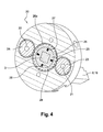
- the slip clutch 20 in the described second embodiment is in Fig. 4 shown in more detail.
- Fig. 4 shows a perspective cross-section along in FIG Fig. 3A drawn section line BB.
- the driver gear 25 has a drive plate 26 which is non-positively connected to the shaft 3 of the tool 1.
- the drive plate 26 is slidably coupled via at least one ball-spring combination 27 with a rotatably mounted around the circumference of the drive plate, provided with teeth ring 25a.
- each of the spring-loaded balls 28 are pressed inwards, ie in the direction of the springs 29, so that the driver gear 25 is decoupled from the drive plate 26.
- the slip clutch is always anxious to intervene again.
- the tool 1 according to a third preferred embodiment is shown in a perspective partial view.
- the adjusting means consists of an adjusting screw 30 and two interacting with this rack and pinion gear, which each drive one of the pins 8, 9.
- Each of the rack gears has a spur gear 31 and a rack 32 connected to the pin 8, 9.
- the rack 32 is arranged, for example, in each case on a foot 15 of a pin 8, 9.
- the adjusting screw 30 is provided with two separate, oppositely extending threads, so that can cooperate with the set screw 30 with two spur gears 31 simultaneously and the pins 8, 9 can be moved in opposite directions.
- the adjusting screw 30 is thread-free.
- the adjusting screw 30 is preferably driven manually. In this case, the translational movement of the adjusting screw 30 is transmitted via the rack gear in opposite translational movements of the pins 8, 9.
- the pins 8, 9 can be moved towards or away from each other so as to adapt their distance to the respective diameter of the screw.
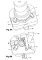
- FIGS. 6A and 6B show, seen from two different sides and in perspective partial views, the tool 1 according to the invention according to a fourth embodiment.
- the adjusting means consists of two each with one of the pins 8, 9 cooperating cams or eccentrics 41, 42, a connecting them transfer bracket 43 and a screw 40.
- the transfer bracket 43 is displaced radially to the axis 4 of the tool 1.
- the rotatably mounted at the ends of the transmission bracket 43 cam 41, 42 are thereby offset in a rotational movement.
- the feet of the pins 8, 9 are provided with corresponding recesses 45, in which the rotating cams 41, 42 are guided.
- the translational movement of the adjusting screw 40 is transmitted via the rotational movements of the cams 41, 42 in translation movements of the pins 8, 9.
- the tool 1 according to the invention can advantageously have a gear.
- the gear 13 is disposed within the housing 2.
- the transmission 13 has a drive or input shaft, on which the drive means can engage, and an output shaft, which coincides with the above-mentioned shaft 3 of the tool 1.
- the transmission 13 amplifies the torque generated at the input shaft to obtain the torque required to tighten the screws. This is necessary if, for example, a wrench or a weaker cordless screwdriver 11 is used as the drive means.
- the gear 13 may be, for example, a planetary thread, in which input and output shafts are arranged coaxially with each other. If a cordless screwdriver is used as the drive means, which generates the necessary torque, the gear 13 is not necessary.
- the screws 12 of the screw connector 10 are preferably shear screws which are sheared off at a predetermined breaking point as soon as a certain torque is reached.
- the above-mentioned preset torque is lower than the torque intended for shearing the screws.
Abstract
Es wird ein Werkzeug (1) zum Befestigen eines Schraubverbinders (10), in dessen rohrförmige Wandung mit einem Gewinde versehene Durchgangslöcher zur Aufnahme von Schrauben angebracht sind, an einem elektrischen Kabel angegeben. Das Werkzeug (1) umfaßt ein Gehäuse (2) und eine in diesem um ihre Achse (4) drehbar angebrachte Welle (3), die an ihrem einem axialen Ende (5) eine Aufnahme für den Kopf einer Schraube (12) und an ihrem anderen axialen Ende (6) eine Anlagefläche für ein zum Drehen der Welle (3) geeignetes Antriebsmittel (11) aufweist. Das Gehäuse (2) weist zwei von diesem in Achsrichtung abstehende, von der Achse (4) der Welle (3) in radialer Richtung gleich weit entfernte Stifte (8, 9) auf, welche in Arbeitsposition an zwei einander gegenüberliegenden Seiten des Schraubverbinders (10) anlegbar sind. Das Werkzeug (1) weist außerdem ein Verstellmittel auf, welches geeignet ist, die Stifte (8, 9) in symmetrischer Weise relativ zueinander und radial zu der Achse (4) zu bewegen.There is provided a tool (1) for attaching a screw connector (10), in the tubular wall of which threaded through holes for receiving screws are attached, to an electrical cable. The tool (1) comprises a housing (2) and in this about its axis (4) rotatably mounted shaft (3) at its one axial end (5) has a receptacle for the head of a screw (12) and at its another axial end (6) has a contact surface for a for rotating the shaft (3) suitable drive means (11). The housing (2) has two pins (8, 9) projecting from the latter in the axial direction and equidistant from the axis (4) of the shaft (3) in a radial direction, which in working position on two opposite sides of the screw connector (10 ) can be applied. The tool (1) further comprises an adjustment means adapted to move the pins (8, 9) symmetrically relative to each other and radially to the axis (4).
Description
Die Erfindung bezieht sich auf ein Werkzeug zum Befestigen eines Schraubverbinders, in dessen rohrförmige Wandung mit einem Gewinde versehene Durchgangslöcher zur Aufnahme von Schrauben angebracht sind, an einem elektrischen Kabel. Das Werkzeug umfaßt ein Gehäuse und eine in diesem um ihre Achse drehbar angebrachte Welle, die an ihrem einem axialen Ende eine Aufnahme für den Kopf einer Schraube und an ihrem anderen axialen Ende eine Anlagefläche für ein zum Drehen der Welle geeignetes Antriebsmittel aufweist. Das Gehäuse weist zwei von diesem in Achsrichtung abstehende, von der Achse der Welle in radialer Richtung gleich weit entfernte Stifte auf, welche in Arbeitsposition an zwei einander gegenüberliegenden Seiten des Schraubverbinders anlegbar sind.The invention relates to a tool for fixing a screw connector, in the tubular wall of which threaded through holes for receiving screws are attached, to an electrical cable. The tool comprises a housing and a shaft rotatably mounted therein about its axis, which has at its one axial end a receptacle for the head of a screw and at its other axial end a bearing surface for a suitable shaft for rotating the drive means. The housing has two of this projecting in the axial direction, from the axis of the shaft in the radial direction equidistant pins, which are in working position on two opposite sides of the screw can be applied.
Der Begriff Schraubverbinder soll sowohl Schraubverbinder im eigentlichen Sinne als auch Schraubkabelschuhe umfassen. Ein Schraubverbinder ist ein rohrförmiger Verbinder aus Metall, in welchem zwei in den Verbinder eingeführte, zu verbindende Kabelenden mittels der in den Durchgangslöchern der Wandung angebrachten Schrauben festgestellt werden können. Ein Schraubkabelschuh ist für die Verbindung von einem Kabelende mit einem anderen elektrischen Bauteil vorgesehen und entsprechend aufgebaut.The term screw connector is intended to include both screw connectors in the true sense as well as Schraubkabelschuhe. A screw connector is a tubular connector made of metal, in which two cable ends inserted into the connector can be fixed by means of the screws mounted in the through-holes of the wall. A Schraubkabelschuh is provided for the connection of a cable end with another electrical component and constructed accordingly.
Um einen sicheren und langzeitstabilen elektrischen Kontakt und einen geringen Übergangswiderstand zwischen dem Leiter und dem Schraubverbinder zu erreichen, muß die Verbindung zwischen Kabel und Schraubverbinder mit ausreichend Kontaktkraft versehen werden. Die Schrauben des Schraubverbinders müssen deshalb mit einem vorbestimmten Drehmoment angezogen werden. Insbesondere bei relativ flexiblen Kabeln für den Nieder- und Mittelspannungsbereich kann es beim Festziehen der Schrauben durch einen Monteur durch die Übertragung des Drehmoments zum Verdrehen des Schraubverbinders und damit der Kabel kommen. Bei kleinen Schraubverbindern oder Schraubkabelschuhen ist es zudem wegen des relativ hohen Anzugsmoments dem Monteur nicht möglich, den Schraubverbinder während des Anziehens in der Hand zu halten.In order to achieve a secure and long-term stable electrical contact and a low contact resistance between the conductor and the screw connector, the connection between the cable and screw connector must be provided with sufficient contact force. The screws of the screw connector must therefore be tightened with a predetermined torque. Especially with relatively flexible cables for the low and medium voltage range, it can come when tightening the screws by a fitter by the transmission of torque for rotating the screw and thus the cable. In small Screw connectors or Schraubkabelschuhen it is also not possible because of the relatively high torque to the installer to hold the screw while tightening in the hand.
Werkzeuge zum Befestigen eines Schraubverbinders an einem Kabelende sind bekannt.Tools for attaching a screw connector to a cable end are known.
Beispielsweise kann der Schraubverbinder in einen mit einem Hebelarm ausgestatteten Gegenhalter eingeklemmt werden. Beim Anziehen der Schrauben durch den Monteur mittels eines Schraubenschlüssels kann dieser dank des Hebelarms der unerwünschten Drehbewegung besser gegenhalten.For example, the screw connector can be clamped in a equipped with a lever arm counter-holder. When tightening the screws by the fitter by means of a wrench this can better counteract the unwanted rotational movement thanks to the lever arm.
Nach einem anderen Beispiel kann ein Drehmomentverstärker zum Festziehen der Schrauben verwendet werden. Ein solches Werkzeug ist zum Beispiel in der
Ein solcher Drehmomentverstärker ist durch den festgelegten Abstand der Stifte zueinander für einen bestimmten Durchmesser des Schraubverbinders vorgesehen. Soll der Drehmomentverstärker für einen Schraubverbinder mit einem anderen Durchmesser verwendet werden, müssen die Stifte aus dem Verstärkergehäuse herausgeschraubt und an anderer, vorgesehener Stelle wieder eingeschraubt werden. Durch den festgelegten Stiftabstand kann es vorkommen, daß zumindest einer der Stifte das Kabel berührt. Dadurch kann es zu einer Beeinträchtigung des elektrischen Kontakts kommen, und die Isolierung des Kabels kann eingedrückt und beschädigt werden. Ebenso kann ein Stift eine andere, neben der gerade festzuziehenden Schraube liegende Schraube des Schraubverbinders berühren, wodurch der Drehmomentverstärker seiner Funktion nicht mehr richtig gerecht werden kann.Such a torque amplifier is provided by the fixed distance of the pins to each other for a given diameter of the screw. If the torque amplifier is to be used for a screw connector with a different diameter, the pins must be unscrewed from the amplifier housing and screwed in at another designated location. Due to the fixed pin spacing, it can happen that at least one of the pins touches the cable. This can lead to a deterioration of the electrical contact, and the insulation of the cable can be pressed and damaged. Likewise, a pin can be another, lying next to the currently tightening screw screw of Schraubverbinders touch, whereby the torque amplifier can no longer properly fulfill its function.
Der Erfindung liegt die Aufgabe zugrunde, ein verbessertes Werkzeug zum Befestigen eines Schraubverbinders an einem elektrischen Kabel bereitzustellen, welches die oben genannten Probleme löst und insbesondere auf einfache Weise kontinuierlich an verschiedene Durchmesser von Schraubverbindern angepaßt werden kann.The invention has for its object to provide an improved tool for attaching a screw to an electrical cable, which solves the above problems and in particular can be adapted continuously in a simple manner to different diameters of screw connectors.
Diese Aufgabe wird gemäß der Erfindung dadurch gelöst, daß das Werkzeug ein Verstellmittel aufweist, welches geeignet ist, die Stifte in symmetrischer Weise relativ zueinander und radial zu der Achse zu bewegen.This object is achieved according to the invention in that the tool has an adjusting means which is adapted to move the pins in a symmetrical manner relative to each other and radially to the axis.
Durch die mittels des Verstellmittels relativ zueinander und radial zu der Achse beweglichen Stifte erlaubt das erfindungsgemäße Werkzeug das Befestigen eines Schraubverbinders beliebigen Durchmessers an einem elektrischen Kabel. Dem Monteur ist es möglich, die Schrauben des Schraubverbinders ohne erheblichen Kraftaufwand anzuziehen. Eine einwandfreie elektrische Verbindung zwischen dem Kabel und dem Schraubverbinder kann so erreicht werden. Das erfindungsgemäße Werkzeug wird mit Vorteil zum Befestigen von Schraubverbindern im Nieder- und Mittelspannungsbereich eingesetzt. Dank des sicheren Greifens des Schraubverbinders und der komfortablen Handhabung des Werkzeugs während der Montage werden Verletzungen des Monteurs vorgebeugt und der Arbeitsschutz so verbessert. Andere Schrauben des Schraubverbinders oder das Kabel werden von dem Werkzeug nicht beeinflußt. Das erfindungsgemäße Werkzeug läßt sich flexibel und kontinuierlich an unterschiedliche Durchmesser von Schraubverbindern anpassen, ohne daß die Stifte neu montiert werden müssen, sodaß das Befestigen des Schraubverbinders an einem Kabel insgesamt zügiger durchgeführt werden kann. Für die Anpassung des Werkzeugs ist vorteilhafterweise keinerlei Sonderwerkzeug nötig.By means of the adjusting means relative to each other and radially to the axis movable pins allows the tool according to the invention the fastening of a screw of any diameter on an electric cable. The installer it is possible to tighten the screws of the screw without considerable effort. A proper electrical connection between the cable and the screw can be achieved. The tool according to the invention is advantageously used for fastening screw connectors in the low and medium voltage range. Thanks to the secure gripping of the screw connector and the comfortable handling of the tool during assembly, injuries to the fitter are prevented and the occupational safety is improved. Other screws of the screw connector or the cable are not affected by the tool. The tool according to the invention can be flexibly and continuously adapted to different diameters of screw connectors without the pins having to be remounted, so that the fastening of the screw connector to a cable can be carried out more rapidly as a whole. For the adaptation of the tool advantageously no special tool is necessary.
Ausführungsbeispiele des Erfindungsgegenstandes sind in den Zeichnungen dargestellt. Es zeigen:
-
Fig. 1 einen Längsschnitt eines erfindungsgemäßen Werkzeugs nach einer ersten Ausführungsform mit einem eingespannten Schraubverbinder, -
Fig. 2A und 2B perspektivische Ansichten eines erfindungsgemäßen Werkzeugs mit einem eingespannten Schraubverbinder, -
Fig. 3A und 3B einen Längsschnitt und einen Querschnitt eines erfindungsgemäßen Werkzeugs nach einer zweiten Ausführungsform, -
Fig. 4 in perspektivischer Ansicht einen Schnitt durch das Werkzeug nachFig. 3A und 3B , -
Fig. 5 eine perspektivische Teilansicht eines erfindungsgemäßen Werkzeugs nach einer dritten Ausführungsform, und -
Fig. 6A und 6B perspektivische Teilansichten eines erfindungsgemäßen Werkzeug nach einer vierten Ausführungsform.
-
Fig. 1 a longitudinal section of a tool according to the invention according to a first embodiment with a clamped screw connector, -
FIGS. 2A and 2B perspective views of a tool according to the invention with a clamped screw connector, -
FIGS. 3A and 3B a longitudinal section and a cross section of a tool according to the invention according to a second embodiment, -
Fig. 4 in perspective view a section through the tool toFIGS. 3A and 3B . -
Fig. 5 a partial perspective view of a tool according to the invention according to a third embodiment, and -
FIGS. 6A and 6B partial perspective views of a tool according to the invention according to a fourth embodiment.
In den Zeichnungen beziehen sich gleiche Bezugszeichen auf gleiche technische Merkmale.In the drawings, like reference numerals refer to like technical features.
In
Von dem Gehäuse 2 stehen in Richtung der Wellenachse 4 zwei Stifte 8, 9 ab. Die Stifte 8, 9, oder Gegenhaltestangen, sind gleich weit von der Achse 4 entfernt. Die Stifte 8, 9 sind parallel zueinander und an zwei einander gegenüberliegenden Seiten an dem Gehäuse 2 angeordnet. In Arbeitsposition, d.h. während des Festziehens einer Schraube 12 an dem Schraubverbinder 10, liegen die Stifte 8, 9 an zwei einander gegenüberliegenden Seiten des Schraubverbinders 10 an dessen äußerem Umfang an. Die Stifte 8, 9 klemmen den Schraubverbinder 10 nach der Art eines Schraubstocks ein. Die Schrauben des Schraubverbinders 10 können dann mit Hilfe des Antriebsmittels durch Drehen der Welle 3 sicher und einfach festgezogen werden, ohne daß der Schraubverbinder 10 verdreht wird.From the
Die Stifte oder Gegenhaltestangen 8, 9 sind vorzugsweise in einer am Gehäuse angeordneten Führungsschiene, z.B. nach Art einer Schlittenführung, aufgenommen. Dies geht beispielsweise aus
Erfindungsgemäß weist das Werkzeug 1 ein Verstellmittel auf. Mit dem Verstellmittel werden die Stifte 8, 9 relativ zueinander und radial zu der Achse 4 der Welle 3 verschoben. Dadurch ist es möglich, das Werkzeug 1 kontinuierlich an verschiedene Durchmesser des Schraubverbinders 10 anzupassen. Im Folgenden werden verschiedene Ausführungsformen des Verstellmittels anhand der
In
Die Rutschkupplung 20 in der beschriebenen zweiten Ausführungsform ist in
In
Das erfindungsgemäße Werkzeug 1 kann mit Vorteil ein Getriebe aufweisen. Dies ist in
Bei den Schrauben 12 des Schraubverbinders 10 handelt es sich mit Vorzug um Scherschrauben, welche an einer Sollbruchstelle abgeschert werden, sobald ein bestimmtes Drehmoment erreicht wird. In diesem Falle ist das oben erwähnte voreingestellte Drehmoment geringer als das zum Scheren der Schrauben bestimmte Drehmoment.The
Claims (10)
Priority Applications (1)
| Application Number | Priority Date | Filing Date | Title |
|---|---|---|---|
| EP14305788.3A EP2949427A1 (en) | 2014-05-27 | 2014-05-27 | Tool for fastening a mechanical connector to an electrical cable |
Applications Claiming Priority (1)
| Application Number | Priority Date | Filing Date | Title |
|---|---|---|---|
| EP14305788.3A EP2949427A1 (en) | 2014-05-27 | 2014-05-27 | Tool for fastening a mechanical connector to an electrical cable |
Publications (1)
| Publication Number | Publication Date |
|---|---|
| EP2949427A1 true EP2949427A1 (en) | 2015-12-02 |
Family
ID=50976557
Family Applications (1)
| Application Number | Title | Priority Date | Filing Date |
|---|---|---|---|
| EP14305788.3A Withdrawn EP2949427A1 (en) | 2014-05-27 | 2014-05-27 | Tool for fastening a mechanical connector to an electrical cable |
Country Status (1)
| Country | Link |
|---|---|
| EP (1) | EP2949427A1 (en) |
Cited By (1)
| Publication number | Priority date | Publication date | Assignee | Title |
|---|---|---|---|---|
| DE202023100468U1 (en) | 2023-01-31 | 2024-02-23 | Techtronic Cordless Gp | Tool for attaching a screw connector |
Citations (2)
| Publication number | Priority date | Publication date | Assignee | Title |
|---|---|---|---|---|
| DE20121205U1 (en) * | 2001-12-21 | 2002-05-23 | Hytec Gmbh Hydraulikwerkzeuge | Screwdrivers |
| EP2244338A1 (en) | 2009-04-22 | 2010-10-27 | Intercable Srl | Tool for fixing screw connectors to electrical cables |
-
2014
- 2014-05-27 EP EP14305788.3A patent/EP2949427A1/en not_active Withdrawn
Patent Citations (2)
| Publication number | Priority date | Publication date | Assignee | Title |
|---|---|---|---|---|
| DE20121205U1 (en) * | 2001-12-21 | 2002-05-23 | Hytec Gmbh Hydraulikwerkzeuge | Screwdrivers |
| EP2244338A1 (en) | 2009-04-22 | 2010-10-27 | Intercable Srl | Tool for fixing screw connectors to electrical cables |
Cited By (1)
| Publication number | Priority date | Publication date | Assignee | Title |
|---|---|---|---|---|
| DE202023100468U1 (en) | 2023-01-31 | 2024-02-23 | Techtronic Cordless Gp | Tool for attaching a screw connector |
Similar Documents
| Publication | Publication Date | Title |
|---|---|---|
| DE112012005764B4 (en) | Electric clamping device | |
| DE2825023A1 (en) | MOTOR DRIVEN COMBINATION MACHINE TOOL | |
| EP2897763B1 (en) | Clamping system with a rotation drive | |
| EP2891826B1 (en) | Electromotive linear drive | |
| DE102010010238A1 (en) | Centric clamp or gripper | |
| EP0239670B1 (en) | Motor-driven machine with torque adjustment, in particular an electrical hand tool | |
| EP2062690B1 (en) | Screw device for a mechanical screw device | |
| DE102011088252B4 (en) | Ratchet attachment for driving screwing tools | |
| EP3372343B1 (en) | Assembly consisting of a torque-discharging support arm and a screwdriver | |
| EP2216555B1 (en) | Tensioning device | |
| EP0840021A1 (en) | Device for connecting assembling elements | |
| EP2949427A1 (en) | Tool for fastening a mechanical connector to an electrical cable | |
| EP3978770B1 (en) | Damper rotary drive and axle housing for a damper rotary drive | |
| DE102007023807B4 (en) | Switching means for screwdrivers with two drives | |
| DE19906268A1 (en) | Arrangement for electrically locking steering shaft of steering device of motor vehicle, has housing containing motor which displaces blocking element connected to adapter that absorbs force if shaft is violently twisted | |
| EP4067716A1 (en) | Tube section mounting device | |
| DE102015005487B4 (en) | Machining system for a workpiece | |
| EP2578891B1 (en) | Adapter | |
| EP1566238A1 (en) | Electric linear drive with a plug coupling between a driving screw and a drive module | |
| DE102015205623B4 (en) | Manual wrench | |
| WO2016166645A2 (en) | Screw tool for actuating a screw element | |
| DE112008003661B4 (en) | Dowel bolts of a connecting device | |
| EP3359339A1 (en) | Gripping or clamping device having an actuator | |
| EP2915608A1 (en) | Compression device for a corrugated pipe | |
| DE202021101343U1 (en) | Flat drive for the assembly of screw connections |
Legal Events
| Date | Code | Title | Description |
|---|---|---|---|
| AK | Designated contracting states |
Kind code of ref document: A1 Designated state(s): AL AT BE BG CH CY CZ DE DK EE ES FI FR GB GR HR HU IE IS IT LI LT LU LV MC MK MT NL NO PL PT RO RS SE SI SK SM TR |
|
| AX | Request for extension of the european patent |
Extension state: BA ME |
|
| PUAI | Public reference made under article 153(3) epc to a published international application that has entered the european phase |
Free format text: ORIGINAL CODE: 0009012 |
|
| 17P | Request for examination filed |
Effective date: 20160602 |
|
| RBV | Designated contracting states (corrected) |
Designated state(s): AL AT BE BG CH CY CZ DE DK EE ES FI FR GB GR HR HU IE IS IT LI LT LU LV MC MK MT NL NO PL PT RO RS SE SI SK SM TR |
|
| GRAP | Despatch of communication of intention to grant a patent |
Free format text: ORIGINAL CODE: EPIDOSNIGR1 |
|
| RIC1 | Information provided on ipc code assigned before grant |
Ipc: B25B 17/02 20060101AFI20161122BHEP |
|
| INTG | Intention to grant announced |
Effective date: 20161206 |
|
| STAA | Information on the status of an ep patent application or granted ep patent |
Free format text: STATUS: THE APPLICATION IS DEEMED TO BE WITHDRAWN |
|
| 18D | Application deemed to be withdrawn |
Effective date: 20170419 |