EP2948748B1 - Dispositif et procédé pour la surveillance et le calibrage d'un dispositif de mesure de la profondeur des sculptures d'un pneu - Google Patents
Dispositif et procédé pour la surveillance et le calibrage d'un dispositif de mesure de la profondeur des sculptures d'un pneu Download PDFInfo
- Publication number
- EP2948748B1 EP2948748B1 EP13807961.1A EP13807961A EP2948748B1 EP 2948748 B1 EP2948748 B1 EP 2948748B1 EP 13807961 A EP13807961 A EP 13807961A EP 2948748 B1 EP2948748 B1 EP 2948748B1
- Authority
- EP
- European Patent Office
- Prior art keywords
- measuring
- monitoring
- image
- calibration
- tyre
- Prior art date
- Legal status (The legal status is an assumption and is not a legal conclusion. Google has not performed a legal analysis and makes no representation as to the accuracy of the status listed.)
- Not-in-force
Links
- 238000012544 monitoring process Methods 0.000 title claims description 56
- 238000000034 method Methods 0.000 title claims description 23
- 238000005096 rolling process Methods 0.000 claims description 10
- 230000001154 acute effect Effects 0.000 claims description 2
- 238000005259 measurement Methods 0.000 description 45
- 238000005286 illumination Methods 0.000 description 27
- 230000003287 optical effect Effects 0.000 description 12
- 238000011156 evaluation Methods 0.000 description 10
- 230000008901 benefit Effects 0.000 description 4
- 230000007613 environmental effect Effects 0.000 description 4
- 230000007774 longterm Effects 0.000 description 3
- 238000012423 maintenance Methods 0.000 description 3
- 239000000725 suspension Substances 0.000 description 3
- 238000010276 construction Methods 0.000 description 2
- 238000006073 displacement reaction Methods 0.000 description 2
- 238000010191 image analysis Methods 0.000 description 2
- 238000003384 imaging method Methods 0.000 description 2
- 238000009434 installation Methods 0.000 description 2
- 230000033001 locomotion Effects 0.000 description 2
- 239000000463 material Substances 0.000 description 2
- 230000008569 process Effects 0.000 description 2
- 238000012360 testing method Methods 0.000 description 2
- 230000004913 activation Effects 0.000 description 1
- 238000004458 analytical method Methods 0.000 description 1
- 230000005540 biological transmission Effects 0.000 description 1
- 230000008859 change Effects 0.000 description 1
- 230000001419 dependent effect Effects 0.000 description 1
- 238000013461 design Methods 0.000 description 1
- 238000001514 detection method Methods 0.000 description 1
- 230000010354 integration Effects 0.000 description 1
- 238000012806 monitoring device Methods 0.000 description 1
- 230000000737 periodic effect Effects 0.000 description 1
- 230000000704 physical effect Effects 0.000 description 1
- 230000009467 reduction Effects 0.000 description 1
- 230000003068 static effect Effects 0.000 description 1
Images


Classifications
-
- G—PHYSICS
- G01—MEASURING; TESTING
- G01M—TESTING STATIC OR DYNAMIC BALANCE OF MACHINES OR STRUCTURES; TESTING OF STRUCTURES OR APPARATUS, NOT OTHERWISE PROVIDED FOR
- G01M17/00—Testing of vehicles
- G01M17/007—Wheeled or endless-tracked vehicles
- G01M17/02—Tyres
- G01M17/027—Tyres using light, e.g. infrared, ultraviolet or holographic techniques
-
- G—PHYSICS
- G01—MEASURING; TESTING
- G01B—MEASURING LENGTH, THICKNESS OR SIMILAR LINEAR DIMENSIONS; MEASURING ANGLES; MEASURING AREAS; MEASURING IRREGULARITIES OF SURFACES OR CONTOURS
- G01B11/00—Measuring arrangements characterised by the use of optical techniques
- G01B11/22—Measuring arrangements characterised by the use of optical techniques for measuring depth
-
- G—PHYSICS
- G01—MEASURING; TESTING
- G01B—MEASURING LENGTH, THICKNESS OR SIMILAR LINEAR DIMENSIONS; MEASURING ANGLES; MEASURING AREAS; MEASURING IRREGULARITIES OF SURFACES OR CONTOURS
- G01B11/00—Measuring arrangements characterised by the use of optical techniques
- G01B11/24—Measuring arrangements characterised by the use of optical techniques for measuring contours or curvatures
- G01B11/25—Measuring arrangements characterised by the use of optical techniques for measuring contours or curvatures by projecting a pattern, e.g. one or more lines, moiré fringes on the object
Definitions
- the invention relates to a device and a method for monitoring and calibrating a device for measuring the tread depth of a tire, in particular a motor vehicle tire.
- the groove-shaped recesses are formed at an acute angle to the road surface.
- the groove-shaped depressions may in particular be formed in a direction to the roadway plane which is parallel to the direction of the in the proper state of the illumination device is emitted and incident in the groove-shaped recesses light.
- a measuring slot 14 with a length L between 500 mm and 700 mm and a width B between 30 mm and 50 mm has proven to be well suited on each vehicle side.
- An illumination device 4 and an image recording device 18 are arranged in the overflow channel 38 such that the measuring range of the image recording device 18 corresponds to the measuring slot 14 in the roadway 16.
- the image recording and the illumination lines are deflected via mirrors 42, 44.
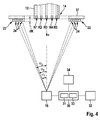
- a symmetrical arrangement of the optical elements 4, 18, 42, 44 ensures that the beam lengths for the illumination device 4 and the image recording device 18 are identical and thus the fan angle of the light planes 5 of the illumination device 4 is the same as the aperture angle ⁇ of the image recording device 18 ,
- An assembly of the optical elements 4, 18, 42, 44 and the measuring and evaluation device 30 on a side wall 39 of the overflow channel 38 protects the optical elements 4, 18, 42, 44 and the measuring and evaluation device 30, for example against backwater collects at the bottom of the overflow channel 38.
- the assembly of all components 4, 18, 42, 44, 32 of the measuring system on a cover 37 of the overflow channel 38 makes it possible to easily maintain and / or replace the components 4, 18, 42, 44, 32.
- the in the FIG. 2 shown arrangement of the illumination device 4 and the image pickup device 18 has the additional advantage that the devices 4, 18 are well protected from possibly falling through the measuring slot 14 dirt.
- the illumination device 4 and the associated optical component 44 are aligned so that the lines of light 6 generated by the illumination device 4 are projected parallel or nearly parallel to the longitudinal side of the measuring slot 14 transversely to the direction of travel F of the vehicle 10 or to the running direction of the tire 12 on its tread ,
- the angle ⁇ denotes the angle between the plane 5, in which the light is irradiated by the illumination device 4 on the tire tread, and the imaging plane 7 at the object point P.
- Image Acquisition Device 18 By measuring the unloaded portion of the tire footprint through the measurement slot 14 in the lane 16, the depth extent of the tire tread, or, in other words, the normal vector n of the tire 12, ensures an identical orientation for each tire 12 at the time of measurement having. In this arrangement, the measuring system is also to calibrate.
- the enlarged view of the tire profile in the FIG. 3b illustrates that, depending on the width and depth of the grooves R1, R2, R3, R4, R5, in the projection of the light lines 6 with increasing opening angle ⁇ of the image recording device 18 shadowing 20 occur that make a profiled depth measurement impossible beyond a certain opening angle ⁇ , because the reason of the grooves R1, R2, R3, R4, R5 is not or only insufficiently illuminated.
- FIG. 4 shows a sectional view of a measuring device which is equipped with an embodiment of a monitoring and calibration device according to the invention.
- a measuring and evaluation unit 30 which is electrically or wirelessly connected to the image recording device 18 and with a computer unit 31, a Memory unit 33 and an evaluation software, performs the analysis of the image data provided by the image pickup device 18, the monitoring of the adjustment, the self-calibration, the calculation of the driving speed of the vehicle 10 and the image analysis to distinguish the tire type, for calculating the tread depth.
- the measurement and evaluation unit 30 may also evaluate a profile depth deviation and areal profile structure per tire, the relative deviation of the tread depths and tread depth deviations of the wheels on each axle, the tread depth, tread depth deviation and tread pattern for each tire based on defined limits, the relative deviation and the difference Evaluate the profile depth deviation of the wheels of an axle using defined limit values, as well as carry out a summary assessment of the tire condition.
- the measurement and evaluation unit 30 also controls a display unit 32 for outputting the test results and, if required, the transmission of the measurement and test results to a higher-level server 34.
- the width of the measuring slot 14 can be reduced, the width of the groove-shaped recesses 24 can be increased and / or the depth of the groove-shaped recesses 24 can be reduced ,
- the groove-like depressions 24 of the monitoring and calibration elements 22 are not like the grooves R1, R2, R3, R4, R5 of a typical tire profile perpendicular to the plane of the roadway 16, ie parallel to the normal vector n of the tire 12, but as obliquely incised groove-shaped Recesses 24 formed.
- the amount of shadowing 20 can be reduced.
- the inclination of the groove-shaped depressions 24 relative to the plane of the road 16 matched to the opening angle ⁇ i of the illumination and image recording devices 4, 18.
- each groove-shaped recess 24 of the monitoring and calibration element 22 is completely illuminated and imaged on the surface image sensor 8 of the image recording device 18. Shadings 20 are reduced or even completely avoided and the best possible measurement information can be used for monitoring and calibration.
- the difference in the depth dK between the footprint of the tire 12 and the surface of the monitoring and calibration element 22 is known and is taken into account in the evaluation.
- the measuring slot 14 and the at least one monitoring and calibration element 22 form a long-term stable unit, so that the position of the monitoring and calibration element 22 with respect to the measuring slot 14 is fixed .
- the monitoring and calibration elements 22 are therefore made in one piece together with the cover 37, in which the measuring slot 14 is formed, so that a change in the position of the monitoring and calibration elements 22 relative to the measuring slot 14 is excluded ,
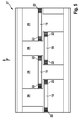
- FIG. 5 shows the underside of an embodiment of such a lid 37 in the plan.
- the cover 37 comprises four transverse to the direction F arranged side by side and identically formed elements 26, wherein adjacent elements 26 are aligned in a respective rotated by 180 ° to each other orientation.
- the elements 26 are designed such that the measuring slots 14 are arranged offset in the direction of travel F against each other.
- a monitoring and calibration element 22 is arranged, as has been described above.
- a mutual disturbance of the measurements can be prevented because it can be excluded that from a lighting device 4, which is associated with a first measuring slot 14, emitted light from an image pickup device 18, which is associated with a second measuring slot 14 , is detected and the evaluation for monitoring and calibration difficult or even prevented.
Landscapes
- Physics & Mathematics (AREA)
- General Physics & Mathematics (AREA)
- Engineering & Computer Science (AREA)
- Computer Vision & Pattern Recognition (AREA)
- Length Measuring Devices By Optical Means (AREA)
Claims (8)
- Dispositif de mesure du profil de la bande de roulement d'un pneu (12), comprenant
un plan de voie de circulation destiné au roulement du pneu (12), dans lequel est configurée au moins une fente de mesure (14),
au moins un appareil d'éclairage (4), lequel est configuré et disposé de telle sorte qu'en fonctionnement, il projette une pluralité de lignes de mesure (6) à travers la fente de mesure (14) sur le profil à mesurer, et
au moins un appareil d'enregistrement d'images (18) qui est configuré pour enregistrer au moins une image d'au moins une zone du profil à mesurer,
l'au moins un appareil d'éclairage (4) et l'au moins un appareil d'enregistrement d'images (18) étant configurés et disposés de telle sorte que la direction d'éclairage de l'appareil d'éclairage (4) et la direction d'enregistrement d'image de l'appareil d'enregistrement d'images (18) ne sont orientées ni parallèlement l'une à l'autre, ni orthogonalement à la bande de roulement du pneu (12), que
au moins un dispositif de surveillance et de calibrage (22) étant configuré sur au moins une fente de mesure (14), le dispositif de surveillance et de calibrage (22) possédant au moins un creux (24) dont le côté ouvert fait face à l'appareil d'éclairage (4) et à l'appareil d'enregistrement d'images (18),
caractérisé en ce que l'au moins un creux (24) est configuré avec un angle aigu par rapport au plan de la voie de circulation (16), l'au moins un creux (24) étant notamment configuré avec un angle par rapport au plan de la voie de circulation (16) qui est parallèle à la direction d'un rayon lumineux émis dans l'état en bonne et due forme de l'appareil d'éclairage (4) et incident dans le creux (24). - Dispositif selon la revendication 1, l'au moins un creux (24) étant configuré sous la forme d'un creux (24) en forme de gorge qui s'étend parallèlement à la direction de roulement du pneu (12).
- Dispositif selon la revendication 1 ou 2, la largeur et/ou la profondeur de l'au moins un creux (24) correspondant à la largeur ou à la profondeur du profil d'un pneu de véhicule (12) type.
- Dispositif selon l'une des revendications précédentes, la fente de mesure (14) et le dispositif de surveillance et de calibrage (22) étant réalisés d'un seul tenant en tant que composants d'un élément commun (37).
- Dispositif selon la revendication 5, l'au moins un appareil d'éclairage (4) et l'au moins un appareil d'enregistrement d'images (18) étant disposés dans une rigole de franchissement (38) et la fente de mesure (14) et le dispositif de surveillance et de calibrage (22) étant notamment formés dans un couvercle (37) de la rigole de franchissement (38).
- Dispositif selon l'une des revendications précédentes, le dispositif possédant plusieurs modules de mesure disposés les uns à côté des autres transversalement à la direction du roulement, chacun des modules de mesure possédant respectivement au moins un appareil d'éclairage (4), au moins un appareil d'enregistrement d'images (18), au moins une fente de mesure (14) et un dispositif de surveillance et de calibrage (22), les fentes de mesure (14) des modules de mesure étant disposées de façon décalées les unes par rapport aux autres, notamment dans la direction du roulement du pneu (12).
- Procédé de surveillance et de calibrage d'un dispositif selon l'une des revendications précédentes, le procédé comprenant :la projection d'un motif lumineux défini sur l'au moins un dispositif de calibrage (22) ;l'enregistrement et l'interprétation de la lumière reflétée par le dispositif de surveillance et de calibrage (22) avec l'appareil d'enregistrement d'images (18) afin de calculer les paramètres de calibrage actuels.
- Procédé de mesure de la profondeur de profil d'au moins un pneu (12) avec un dispositif selon l'une des revendications précédentes, le procédé comprenant la mise en oeuvre périodique d'un procédé de surveillance et de calibrage du dispositif selon la revendication 8.
Applications Claiming Priority (2)
| Application Number | Priority Date | Filing Date | Title |
|---|---|---|---|
| DE102013200919.4A DE102013200919A1 (de) | 2013-01-22 | 2013-01-22 | Vorrichtung und Verfahren zum Überwachen und Kalibrieren einer Vorrichtung zur Messung der Profiltiefe eines Reifens |
| PCT/EP2013/075904 WO2014114403A1 (fr) | 2013-01-22 | 2013-12-09 | Dispositif et procédé pour la surveillance et le calibrage d'un dispositif de mesure de la profondeur des sculptures d'un pneu |
Publications (2)
| Publication Number | Publication Date |
|---|---|
| EP2948748A1 EP2948748A1 (fr) | 2015-12-02 |
| EP2948748B1 true EP2948748B1 (fr) | 2016-09-21 |
Family
ID=49779870
Family Applications (1)
| Application Number | Title | Priority Date | Filing Date |
|---|---|---|---|
| EP13807961.1A Not-in-force EP2948748B1 (fr) | 2013-01-22 | 2013-12-09 | Dispositif et procédé pour la surveillance et le calibrage d'un dispositif de mesure de la profondeur des sculptures d'un pneu |
Country Status (5)
| Country | Link |
|---|---|
| US (1) | US9476801B2 (fr) |
| EP (1) | EP2948748B1 (fr) |
| CN (1) | CN104937389B (fr) |
| DE (1) | DE102013200919A1 (fr) |
| WO (1) | WO2014114403A1 (fr) |
Families Citing this family (28)
| Publication number | Priority date | Publication date | Assignee | Title |
|---|---|---|---|---|
| US9805697B1 (en) | 2012-06-01 | 2017-10-31 | Hunter Engineering Company | Method for tire tread depth modeling and image annotation |
| US9046446B1 (en) | 2013-02-22 | 2015-06-02 | Hunter Engineering Company | Method and apparatus for environmental protection of drive-over tire tread depth optical sensors |
| US10063837B2 (en) * | 2013-07-25 | 2018-08-28 | TIREAUDIT.COM, Inc. | System and method for analysis of surface features |
| DE202014007337U1 (de) * | 2014-09-15 | 2015-12-18 | Api International Ag | Reifenprofilerfassungsvorrichtung |
| US20160309135A1 (en) | 2015-04-20 | 2016-10-20 | Ilia Ovsiannikov | Concurrent rgbz sensor and system |
| US11002531B2 (en) | 2015-04-20 | 2021-05-11 | Samsung Electronics Co., Ltd. | CMOS image sensor for RGB imaging and depth measurement with laser sheet scan |
| US10145678B2 (en) * | 2015-04-20 | 2018-12-04 | Samsung Electronics Co., Ltd. | CMOS image sensor for depth measurement using triangulation with point scan |
| US10250833B2 (en) | 2015-04-20 | 2019-04-02 | Samsung Electronics Co., Ltd. | Timestamp calibration of the 3D camera with epipolar line laser point scanning |
| US11736832B2 (en) | 2015-04-20 | 2023-08-22 | Samsung Electronics Co., Ltd. | Timestamp calibration of the 3D camera with epipolar line laser point scanning |
| WO2017004297A1 (fr) * | 2015-06-30 | 2017-01-05 | Bridgestone Americas Tire Operations, Llc | Dispositif de déclenchement à double axe pour essai de pneu |
| US9921133B2 (en) * | 2015-07-29 | 2018-03-20 | Hon Hai Precision Industry Co., Ltd. | Tread depth measuring system |
| TWI559068B (zh) * | 2015-12-11 | 2016-11-21 | 晶睿通訊股份有限公司 | 照明設備及其視野校準方法 |
| CN111879532B (zh) * | 2015-12-17 | 2022-04-15 | 倍耐力轮胎股份公司 | 用于检查轮胎的方法 |
| WO2017115230A1 (fr) * | 2015-12-28 | 2017-07-06 | Pirelli Tyre S.P.A. | Procédé de gestion d'un appareil de contrôle de pneu et appareil de contrôle de pneu conçu pour fonctionner selon ce procédé |
| US11472234B2 (en) | 2016-03-04 | 2022-10-18 | TIREAUDIT.COM, Inc. | Mesh registration system and method for diagnosing tread wear |
| US10789773B2 (en) | 2016-03-04 | 2020-09-29 | TIREAUDIT.COM, Inc. | Mesh registration system and method for diagnosing tread wear |
| EP3739289A1 (fr) * | 2016-04-25 | 2020-11-18 | Sigmavision Limited | Mesure de profondeur de bande de roulement |
| EP3495767B1 (fr) * | 2017-12-11 | 2022-01-05 | Butler Engineering & Marketing S.p.A. | Unité de détection de caractéristiques géométriques d'un composant d'une roue à pneumatique d'un véhicule |
| CN108362218A (zh) * | 2018-01-31 | 2018-08-03 | 浙江浙大鸣泉科技有限公司 | 一种轮胎花纹深度的测量装置 |
| US11453259B2 (en) * | 2018-02-01 | 2022-09-27 | Pixart Imaging Inc. | Object surface managing method and object surface managing system |
| CN108444420B (zh) * | 2018-03-02 | 2019-10-29 | 沈阳飞机工业(集团)有限公司 | 一种零件化铣减重槽的检验方法 |
| WO2019232145A1 (fr) * | 2018-05-30 | 2019-12-05 | Tire Profiles, Llc | Dispositif de mesure de profondeur de bande de roulement de pneu de type banc à protection contre l'eau |
| CN109916327B (zh) * | 2019-04-08 | 2021-10-29 | 浙江江兴汽车检测设备有限公司 | 一种汽车轮胎花纹深度测试仪及其使用方法 |
| CN110220473A (zh) * | 2019-06-05 | 2019-09-10 | 陈子昂 | 轮胎花纹沟深度测量方法、装置及设备 |
| US11338621B2 (en) | 2019-11-26 | 2022-05-24 | Hunter Engineering Company | Drive-over tire tread measurement system for heavy-duty multi-axle vehicles |
| CN113942347B (zh) * | 2020-07-16 | 2022-09-09 | 比亚迪股份有限公司 | 用于车辆的轮胎磨损检测系统和车辆 |
| CN112378344A (zh) * | 2020-11-09 | 2021-02-19 | 深圳市二郎神视觉科技有限公司 | 一种轮胎花纹深度测量装置、方法及计算机可读存储介质 |
| WO2023282276A1 (fr) * | 2021-07-07 | 2023-01-12 | 株式会社村田製作所 | Dispositif d'observation de pneu |
Family Cites Families (11)
| Publication number | Priority date | Publication date | Assignee | Title |
|---|---|---|---|---|
| DE1809459A1 (de) * | 1968-11-18 | 1970-06-11 | Dr Ekkehard Fuchs | Verfahren und Anordnung zur Messung der Profiltiefe von Kraftfahrzeugreifen und zur Auswertung der Messergebnisse |
| FR2665255A1 (fr) | 1990-07-24 | 1992-01-31 | Inrets | Dispositif pour evaluer le degre d'usure des pneumatiques de vehicules. |
| TW341654B (en) * | 1995-05-26 | 1998-10-01 | Burger Joachim | Tread depth measuring device |
| DE19705047A1 (de) | 1997-02-03 | 1998-08-06 | Buerger Joachim | Verfahren und Vorrichtung zur Messung der Profiltiefe eines Kraftfahrzeugreifens |
| DE10239765C5 (de) | 2002-08-29 | 2010-02-18 | Maha Maschinenbau Haldenwang Gmbh & Co. Kg | Profiltiefenmeßvorrichtung |
| WO2007059935A1 (fr) * | 2005-11-22 | 2007-05-31 | Yarayan, Ali | Appareil concu pour controler la profondeur et le type de la sculpture de pneu, la vitesse et la garde au sol sur des vehicules en deplacement |
| DE102006062447B4 (de) | 2006-12-28 | 2009-08-20 | Chronos Vision Gmbh | Verfahren und Vorrichtung zur Erfassung der dreidimensionalen Oberfläche eines Objekts, insbesondere eines Fahrzeugreifens |
| JP2008185511A (ja) * | 2007-01-31 | 2008-08-14 | Bridgestone Corp | タイヤのrro計測方法とその装置 |
| US7578180B2 (en) | 2007-06-29 | 2009-08-25 | The Goodyear Tire & Rubber Company | Tread depth sensing device and method for measuring same |
| US8222593B2 (en) * | 2010-09-23 | 2012-07-17 | The Goodyear Tire & Rubber Company | Stock thickness anomaly detection device |
| DE102012224260A1 (de) * | 2012-12-21 | 2014-06-26 | Robert Bosch Gmbh | Vorrichtung und Verfahren zur Messung der Profiltiefe eines Reifens |
-
2013
- 2013-01-22 DE DE102013200919.4A patent/DE102013200919A1/de not_active Withdrawn
- 2013-12-09 CN CN201380071154.3A patent/CN104937389B/zh not_active Expired - Fee Related
- 2013-12-09 WO PCT/EP2013/075904 patent/WO2014114403A1/fr active Application Filing
- 2013-12-09 US US14/761,041 patent/US9476801B2/en active Active
- 2013-12-09 EP EP13807961.1A patent/EP2948748B1/fr not_active Not-in-force
Also Published As
| Publication number | Publication date |
|---|---|
| CN104937389B (zh) | 2018-10-16 |
| DE102013200919A1 (de) | 2014-07-24 |
| US20160069779A1 (en) | 2016-03-10 |
| WO2014114403A1 (fr) | 2014-07-31 |
| CN104937389A (zh) | 2015-09-23 |
| US9476801B2 (en) | 2016-10-25 |
| EP2948748A1 (fr) | 2015-12-02 |
Similar Documents
| Publication | Publication Date | Title |
|---|---|---|
| EP2948748B1 (fr) | Dispositif et procédé pour la surveillance et le calibrage d'un dispositif de mesure de la profondeur des sculptures d'un pneu | |
| EP2936049B1 (fr) | Dispositif et procédé de mesure de la profondeur des sculptures d'un pneu | |
| EP1042643B1 (fr) | Dispositif de determination de la geometrie de roues et/ou d'essieux de vehicules a moteur | |
| EP2539117B1 (fr) | Procédé et dispositif pour déterminer des distances sur un véhicule | |
| EP2321618B1 (fr) | Dispositif et procédé de détermination et de réglage de la géométrie d'un châssis de véhicule à moteur | |
| WO2009062475A2 (fr) | Procédé pour déterminer la pression et la profondeur de sculpture d'un pneumatique de véhicule | |
| EP1042644B1 (fr) | Dispositif de determination de la geometrie de roues et/ou d'essieux de vehicules a moteur | |
| DE102009016498A1 (de) | Verfahren und Vorrichtung zum Ermitteln der Profiltiefe eines Fahrzeugreifens | |
| EP2064532B1 (fr) | Système pour déterminer la pression dans un pneumatique de véhicule et/ou la vitesse du véhicule | |
| EP1969308A1 (fr) | Procédé de mesure optique de châssis | |
| EP3550322B1 (fr) | Segment d'étalonnage destiné à l'étalonnage d'un système de mesure et procédé d'étalonnage d'un système de mesure | |
| EP2049870A1 (fr) | Procédé de détermination de l'axe de rotation et du centre de rotation d'une roue de véhicule | |
| EP2948733B1 (fr) | Procédé et dispositif destinés à déterminer la géométrie d'un véhicule | |
| DE102012215754A1 (de) | Verfahren und Vorrichtung zur Fahrzeugvermessung | |
| WO2018145829A1 (fr) | Procédé de détection sans contact de la géométrie d'une voie ferrée | |
| DE102018130481A1 (de) | Vorrichtung und Verfahren zur Nicht-Geradeauslaufen-Überprüfung eines Fahrzeuges | |
| DE102017105209A1 (de) | Bestimmung von Neigungswinkeln mit einem Laserscanner | |
| DE102013021475A1 (de) | Optische Lenkwinkelbestimmung | |
| EP3407010B1 (fr) | Dispositif et procédé pour mesurer la profondeur du profil d'un pneu | |
| DE19949982C2 (de) | Verfahren und Einrichtung zum Überprüfen von Radaufhängungskomponenten | |
| DE102017208810A1 (de) | Vorrichtung und Verfahren zur Messung der Profiltiefe eines Reifens | |
| EP4328540A1 (fr) | Dispositif et procédé de mesure de la profondeur de sculpture de pneus de véhicule | |
| EP1930688A1 (fr) | Procédé de mesure optique du mécanisme de déplacement |
Legal Events
| Date | Code | Title | Description |
|---|---|---|---|
| PUAI | Public reference made under article 153(3) epc to a published international application that has entered the european phase |
Free format text: ORIGINAL CODE: 0009012 |
|
| 17P | Request for examination filed |
Effective date: 20150824 |
|
| AK | Designated contracting states |
Kind code of ref document: A1 Designated state(s): AL AT BE BG CH CY CZ DE DK EE ES FI FR GB GR HR HU IE IS IT LI LT LU LV MC MK MT NL NO PL PT RO RS SE SI SK SM TR |
|
| AX | Request for extension of the european patent |
Extension state: BA ME |
|
| DAX | Request for extension of the european patent (deleted) | ||
| REG | Reference to a national code |
Ref country code: DE Ref legal event code: R079 Ref document number: 502013004726 Country of ref document: DE Free format text: PREVIOUS MAIN CLASS: G01M0017020000 Ipc: G01B0011240000 |
|
| GRAP | Despatch of communication of intention to grant a patent |
Free format text: ORIGINAL CODE: EPIDOSNIGR1 |
|
| RIC1 | Information provided on ipc code assigned before grant |
Ipc: G01M 17/02 20060101ALI20160518BHEP Ipc: G01B 11/24 20060101AFI20160518BHEP Ipc: G01B 11/22 20060101ALI20160518BHEP Ipc: G01B 11/25 20060101ALI20160518BHEP |
|
| INTG | Intention to grant announced |
Effective date: 20160609 |
|
| GRAS | Grant fee paid |
Free format text: ORIGINAL CODE: EPIDOSNIGR3 |
|
| GRAA | (expected) grant |
Free format text: ORIGINAL CODE: 0009210 |
|
| AK | Designated contracting states |
Kind code of ref document: B1 Designated state(s): AL AT BE BG CH CY CZ DE DK EE ES FI FR GB GR HR HU IE IS IT LI LT LU LV MC MK MT NL NO PL PT RO RS SE SI SK SM TR |
|
| REG | Reference to a national code |
Ref country code: GB Ref legal event code: FG4D Free format text: NOT ENGLISH |
|
| REG | Reference to a national code |
Ref country code: CH Ref legal event code: EP |
|
| REG | Reference to a national code |
Ref country code: AT Ref legal event code: REF Ref document number: 831407 Country of ref document: AT Kind code of ref document: T Effective date: 20161015 |
|
| REG | Reference to a national code |
Ref country code: IE Ref legal event code: FG4D Free format text: LANGUAGE OF EP DOCUMENT: GERMAN |
|
| REG | Reference to a national code |
Ref country code: DE Ref legal event code: R096 Ref document number: 502013004726 Country of ref document: DE |
|
| REG | Reference to a national code |
Ref country code: FR Ref legal event code: PLFP Year of fee payment: 4 |
|
| REG | Reference to a national code |
Ref country code: LT Ref legal event code: MG4D Ref country code: NL Ref legal event code: MP Effective date: 20160921 |
|
| PG25 | Lapsed in a contracting state [announced via postgrant information from national office to epo] |
Ref country code: RS Free format text: LAPSE BECAUSE OF FAILURE TO SUBMIT A TRANSLATION OF THE DESCRIPTION OR TO PAY THE FEE WITHIN THE PRESCRIBED TIME-LIMIT Effective date: 20160921 Ref country code: LT Free format text: LAPSE BECAUSE OF FAILURE TO SUBMIT A TRANSLATION OF THE DESCRIPTION OR TO PAY THE FEE WITHIN THE PRESCRIBED TIME-LIMIT Effective date: 20160921 Ref country code: NO Free format text: LAPSE BECAUSE OF FAILURE TO SUBMIT A TRANSLATION OF THE DESCRIPTION OR TO PAY THE FEE WITHIN THE PRESCRIBED TIME-LIMIT Effective date: 20161221 Ref country code: FI Free format text: LAPSE BECAUSE OF FAILURE TO SUBMIT A TRANSLATION OF THE DESCRIPTION OR TO PAY THE FEE WITHIN THE PRESCRIBED TIME-LIMIT Effective date: 20160921 |
|
| PG25 | Lapsed in a contracting state [announced via postgrant information from national office to epo] |
Ref country code: NL Free format text: LAPSE BECAUSE OF FAILURE TO SUBMIT A TRANSLATION OF THE DESCRIPTION OR TO PAY THE FEE WITHIN THE PRESCRIBED TIME-LIMIT Effective date: 20160921 Ref country code: SE Free format text: LAPSE BECAUSE OF FAILURE TO SUBMIT A TRANSLATION OF THE DESCRIPTION OR TO PAY THE FEE WITHIN THE PRESCRIBED TIME-LIMIT Effective date: 20160921 Ref country code: LV Free format text: LAPSE BECAUSE OF FAILURE TO SUBMIT A TRANSLATION OF THE DESCRIPTION OR TO PAY THE FEE WITHIN THE PRESCRIBED TIME-LIMIT Effective date: 20160921 Ref country code: GR Free format text: LAPSE BECAUSE OF FAILURE TO SUBMIT A TRANSLATION OF THE DESCRIPTION OR TO PAY THE FEE WITHIN THE PRESCRIBED TIME-LIMIT Effective date: 20161222 |
|
| PG25 | Lapsed in a contracting state [announced via postgrant information from national office to epo] |
Ref country code: RO Free format text: LAPSE BECAUSE OF FAILURE TO SUBMIT A TRANSLATION OF THE DESCRIPTION OR TO PAY THE FEE WITHIN THE PRESCRIBED TIME-LIMIT Effective date: 20160921 Ref country code: EE Free format text: LAPSE BECAUSE OF FAILURE TO SUBMIT A TRANSLATION OF THE DESCRIPTION OR TO PAY THE FEE WITHIN THE PRESCRIBED TIME-LIMIT Effective date: 20160921 |
|
| PG25 | Lapsed in a contracting state [announced via postgrant information from national office to epo] |
Ref country code: ES Free format text: LAPSE BECAUSE OF FAILURE TO SUBMIT A TRANSLATION OF THE DESCRIPTION OR TO PAY THE FEE WITHIN THE PRESCRIBED TIME-LIMIT Effective date: 20160921 Ref country code: PL Free format text: LAPSE BECAUSE OF FAILURE TO SUBMIT A TRANSLATION OF THE DESCRIPTION OR TO PAY THE FEE WITHIN THE PRESCRIBED TIME-LIMIT Effective date: 20160921 Ref country code: IS Free format text: LAPSE BECAUSE OF FAILURE TO SUBMIT A TRANSLATION OF THE DESCRIPTION OR TO PAY THE FEE WITHIN THE PRESCRIBED TIME-LIMIT Effective date: 20170121 Ref country code: SM Free format text: LAPSE BECAUSE OF FAILURE TO SUBMIT A TRANSLATION OF THE DESCRIPTION OR TO PAY THE FEE WITHIN THE PRESCRIBED TIME-LIMIT Effective date: 20160921 Ref country code: CZ Free format text: LAPSE BECAUSE OF FAILURE TO SUBMIT A TRANSLATION OF THE DESCRIPTION OR TO PAY THE FEE WITHIN THE PRESCRIBED TIME-LIMIT Effective date: 20160921 Ref country code: SK Free format text: LAPSE BECAUSE OF FAILURE TO SUBMIT A TRANSLATION OF THE DESCRIPTION OR TO PAY THE FEE WITHIN THE PRESCRIBED TIME-LIMIT Effective date: 20160921 Ref country code: PT Free format text: LAPSE BECAUSE OF FAILURE TO SUBMIT A TRANSLATION OF THE DESCRIPTION OR TO PAY THE FEE WITHIN THE PRESCRIBED TIME-LIMIT Effective date: 20170123 Ref country code: BE Free format text: LAPSE BECAUSE OF NON-PAYMENT OF DUE FEES Effective date: 20161231 Ref country code: BG Free format text: LAPSE BECAUSE OF FAILURE TO SUBMIT A TRANSLATION OF THE DESCRIPTION OR TO PAY THE FEE WITHIN THE PRESCRIBED TIME-LIMIT Effective date: 20161221 |
|
| REG | Reference to a national code |
Ref country code: DE Ref legal event code: R097 Ref document number: 502013004726 Country of ref document: DE |
|
| PLBE | No opposition filed within time limit |
Free format text: ORIGINAL CODE: 0009261 |
|
| STAA | Information on the status of an ep patent application or granted ep patent |
Free format text: STATUS: NO OPPOSITION FILED WITHIN TIME LIMIT |
|
| PG25 | Lapsed in a contracting state [announced via postgrant information from national office to epo] |
Ref country code: DK Free format text: LAPSE BECAUSE OF FAILURE TO SUBMIT A TRANSLATION OF THE DESCRIPTION OR TO PAY THE FEE WITHIN THE PRESCRIBED TIME-LIMIT Effective date: 20160921 |
|
| REG | Reference to a national code |
Ref country code: CH Ref legal event code: PL |
|
| 26N | No opposition filed |
Effective date: 20170622 |
|
| PG25 | Lapsed in a contracting state [announced via postgrant information from national office to epo] |
Ref country code: MC Free format text: LAPSE BECAUSE OF FAILURE TO SUBMIT A TRANSLATION OF THE DESCRIPTION OR TO PAY THE FEE WITHIN THE PRESCRIBED TIME-LIMIT Effective date: 20160921 |
|
| REG | Reference to a national code |
Ref country code: IE Ref legal event code: MM4A |
|
| PG25 | Lapsed in a contracting state [announced via postgrant information from national office to epo] |
Ref country code: CH Free format text: LAPSE BECAUSE OF NON-PAYMENT OF DUE FEES Effective date: 20161231 Ref country code: LI Free format text: LAPSE BECAUSE OF NON-PAYMENT OF DUE FEES Effective date: 20161231 Ref country code: LU Free format text: LAPSE BECAUSE OF NON-PAYMENT OF DUE FEES Effective date: 20161209 |
|
| PG25 | Lapsed in a contracting state [announced via postgrant information from national office to epo] |
Ref country code: SI Free format text: LAPSE BECAUSE OF FAILURE TO SUBMIT A TRANSLATION OF THE DESCRIPTION OR TO PAY THE FEE WITHIN THE PRESCRIBED TIME-LIMIT Effective date: 20160921 Ref country code: IE Free format text: LAPSE BECAUSE OF NON-PAYMENT OF DUE FEES Effective date: 20161209 |
|
| REG | Reference to a national code |
Ref country code: FR Ref legal event code: PLFP Year of fee payment: 5 |
|
| REG | Reference to a national code |
Ref country code: BE Ref legal event code: MM Effective date: 20161231 |
|
| PG25 | Lapsed in a contracting state [announced via postgrant information from national office to epo] |
Ref country code: HU Free format text: LAPSE BECAUSE OF FAILURE TO SUBMIT A TRANSLATION OF THE DESCRIPTION OR TO PAY THE FEE WITHIN THE PRESCRIBED TIME-LIMIT; INVALID AB INITIO Effective date: 20131209 |
|
| PG25 | Lapsed in a contracting state [announced via postgrant information from national office to epo] |
Ref country code: HR Free format text: LAPSE BECAUSE OF FAILURE TO SUBMIT A TRANSLATION OF THE DESCRIPTION OR TO PAY THE FEE WITHIN THE PRESCRIBED TIME-LIMIT Effective date: 20160921 Ref country code: MK Free format text: LAPSE BECAUSE OF FAILURE TO SUBMIT A TRANSLATION OF THE DESCRIPTION OR TO PAY THE FEE WITHIN THE PRESCRIBED TIME-LIMIT Effective date: 20160921 Ref country code: CY Free format text: LAPSE BECAUSE OF FAILURE TO SUBMIT A TRANSLATION OF THE DESCRIPTION OR TO PAY THE FEE WITHIN THE PRESCRIBED TIME-LIMIT Effective date: 20160921 |
|
| GBPC | Gb: european patent ceased through non-payment of renewal fee |
Effective date: 20171209 |
|
| PG25 | Lapsed in a contracting state [announced via postgrant information from national office to epo] |
Ref country code: MT Free format text: LAPSE BECAUSE OF FAILURE TO SUBMIT A TRANSLATION OF THE DESCRIPTION OR TO PAY THE FEE WITHIN THE PRESCRIBED TIME-LIMIT Effective date: 20160921 |
|
| PG25 | Lapsed in a contracting state [announced via postgrant information from national office to epo] |
Ref country code: TR Free format text: LAPSE BECAUSE OF FAILURE TO SUBMIT A TRANSLATION OF THE DESCRIPTION OR TO PAY THE FEE WITHIN THE PRESCRIBED TIME-LIMIT Effective date: 20160921 Ref country code: AL Free format text: LAPSE BECAUSE OF FAILURE TO SUBMIT A TRANSLATION OF THE DESCRIPTION OR TO PAY THE FEE WITHIN THE PRESCRIBED TIME-LIMIT Effective date: 20160921 |
|
| PG25 | Lapsed in a contracting state [announced via postgrant information from national office to epo] |
Ref country code: GB Free format text: LAPSE BECAUSE OF NON-PAYMENT OF DUE FEES Effective date: 20171209 |
|
| REG | Reference to a national code |
Ref country code: DE Ref legal event code: R082 Ref document number: 502013004726 Country of ref document: DE Representative=s name: SCHMITT-NILSON SCHRAUD WAIBEL WOHLFROM PATENTA, DE Ref country code: DE Ref legal event code: R081 Ref document number: 502013004726 Country of ref document: DE Owner name: BEISSBARTH GMBH, DE Free format text: FORMER OWNER: ROBERT BOSCH GMBH, 70469 STUTTGART, DE |
|
| REG | Reference to a national code |
Ref country code: AT Ref legal event code: MM01 Ref document number: 831407 Country of ref document: AT Kind code of ref document: T Effective date: 20181209 |
|
| PGFP | Annual fee paid to national office [announced via postgrant information from national office to epo] |
Ref country code: FR Payment date: 20191218 Year of fee payment: 7 |
|
| PG25 | Lapsed in a contracting state [announced via postgrant information from national office to epo] |
Ref country code: AT Free format text: LAPSE BECAUSE OF NON-PAYMENT OF DUE FEES Effective date: 20181209 |
|
| PG25 | Lapsed in a contracting state [announced via postgrant information from national office to epo] |
Ref country code: FR Free format text: LAPSE BECAUSE OF NON-PAYMENT OF DUE FEES Effective date: 20201231 |
|
| PGFP | Annual fee paid to national office [announced via postgrant information from national office to epo] |
Ref country code: DE Payment date: 20220228 Year of fee payment: 9 |
|
| PGFP | Annual fee paid to national office [announced via postgrant information from national office to epo] |
Ref country code: IT Payment date: 20211230 Year of fee payment: 9 |
|
| REG | Reference to a national code |
Ref country code: DE Ref legal event code: R119 Ref document number: 502013004726 Country of ref document: DE |
|
| PG25 | Lapsed in a contracting state [announced via postgrant information from national office to epo] |
Ref country code: DE Free format text: LAPSE BECAUSE OF NON-PAYMENT OF DUE FEES Effective date: 20230701 |
|
| PG25 | Lapsed in a contracting state [announced via postgrant information from national office to epo] |
Ref country code: IT Free format text: LAPSE BECAUSE OF NON-PAYMENT OF DUE FEES Effective date: 20221209 |