EP2948660B1 - Gasturbinenanlage zur stromerzeugung und verfahren zum betreiben dieser anlage - Google Patents
Gasturbinenanlage zur stromerzeugung und verfahren zum betreiben dieser anlage Download PDFInfo
- Publication number
- EP2948660B1 EP2948660B1 EP14714327.5A EP14714327A EP2948660B1 EP 2948660 B1 EP2948660 B1 EP 2948660B1 EP 14714327 A EP14714327 A EP 14714327A EP 2948660 B1 EP2948660 B1 EP 2948660B1
- Authority
- EP
- European Patent Office
- Prior art keywords
- heat
- sensitive elements
- basis
- temperature values
- detected
- Prior art date
- Legal status (The legal status is an assumption and is not a legal conclusion. Google has not performed a legal analysis and makes no representation as to the accuracy of the status listed.)
- Active
Links
Images


Classifications
-
- F—MECHANICAL ENGINEERING; LIGHTING; HEATING; WEAPONS; BLASTING
- F02—COMBUSTION ENGINES; HOT-GAS OR COMBUSTION-PRODUCT ENGINE PLANTS
- F02C—GAS-TURBINE PLANTS; AIR INTAKES FOR JET-PROPULSION PLANTS; CONTROLLING FUEL SUPPLY IN AIR-BREATHING JET-PROPULSION PLANTS
- F02C9/00—Controlling gas-turbine plants; Controlling fuel supply in air- breathing jet-propulsion plants
- F02C9/26—Control of fuel supply
- F02C9/28—Regulating systems responsive to plant or ambient parameters, e.g. temperature, pressure, rotor speed
-
- F—MECHANICAL ENGINEERING; LIGHTING; HEATING; WEAPONS; BLASTING
- F23—COMBUSTION APPARATUS; COMBUSTION PROCESSES
- F23N—REGULATING OR CONTROLLING COMBUSTION
- F23N5/00—Systems for controlling combustion
- F23N5/02—Systems for controlling combustion using devices responsive to thermal changes or to thermal expansion of a medium
- F23N5/10—Systems for controlling combustion using devices responsive to thermal changes or to thermal expansion of a medium using thermocouples
- F23N5/102—Systems for controlling combustion using devices responsive to thermal changes or to thermal expansion of a medium using thermocouples using electronic means
-
- F—MECHANICAL ENGINEERING; LIGHTING; HEATING; WEAPONS; BLASTING
- F23—COMBUSTION APPARATUS; COMBUSTION PROCESSES
- F23R—GENERATING COMBUSTION PRODUCTS OF HIGH PRESSURE OR HIGH VELOCITY, e.g. GAS-TURBINE COMBUSTION CHAMBERS
- F23R3/00—Continuous combustion chambers using liquid or gaseous fuel
- F23R3/42—Continuous combustion chambers using liquid or gaseous fuel characterised by the arrangement or form of the flame tubes or combustion chambers
- F23R3/52—Toroidal combustion chambers
-
- F—MECHANICAL ENGINEERING; LIGHTING; HEATING; WEAPONS; BLASTING
- F23—COMBUSTION APPARATUS; COMBUSTION PROCESSES
- F23N—REGULATING OR CONTROLLING COMBUSTION
- F23N2225/00—Measuring
- F23N2225/08—Measuring temperature
-
- F—MECHANICAL ENGINEERING; LIGHTING; HEATING; WEAPONS; BLASTING
- F23—COMBUSTION APPARATUS; COMBUSTION PROCESSES
- F23N—REGULATING OR CONTROLLING COMBUSTION
- F23N2241/00—Applications
- F23N2241/20—Gas turbines
-
- F—MECHANICAL ENGINEERING; LIGHTING; HEATING; WEAPONS; BLASTING
- F23—COMBUSTION APPARATUS; COMBUSTION PROCESSES
- F23N—REGULATING OR CONTROLLING COMBUSTION
- F23N2900/00—Special features of, or arrangements for controlling combustion
- F23N2900/05005—Mounting arrangements for sensing, detecting or measuring devices
Definitions
- the present invention relates to a gas turbine plant for electric energy production and to a method for operating said plant.
- Gas turbine plants comprising a compressor, a combustion chamber and a turbine.
- the compressor is configured to intake air, compress it and send it to the combustion chamber.
- the combustion of the fuel and of the air from the compressor occurs in the combustion chamber.
- the flue gases are exhausted into the turbine and expanded by the turbine, thus generating mechanical power.
- the mechanical power generated serves in part to drag the compressor and in part to generate electric energy by means of an alternator.
- This type of plants generally comprises a control device, which is configured to regulate a plurality of parameters of the plant.
- control device in known plants is usually configured to control variables which are not directly correlated with the dynamics of the combustion.
- the present invention relates to gas turbine plant according to claim 1.
- the plant according to the present invention is capable of monitoring the dynamics inside the combustion chamber and, accordingly, of increasing both the reliability and the stability of the combustion process with undeniable advantages in terms of plant performance and profitability.
- the present invention relates to a method for operating a plant according to claim 12.
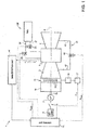
- Numeral 1 in figure 1 indicates a plant for electric energy production comprising a compressor 3, a combustion chamber 4, a gas turbine 5 and a generator 7, which transforms the mechanical power supplied by turbine 5 into electric power to be supplied to an electric network 8 connected to generator 7 by means of a switch 9.
- Plant 1 is also provided with a cooling circuit 10, a data detection unit 11, which is configured to detect a plurality of parameters of plant 1, and with a control unit 12.
- plant 1 is of the combined-cycle type and in addition to comprising the gas turbine 5 and generator 7, it also comprises a steam turbo assembly.
- the gas turbine 5 extends along a longitudinal axis A and is provided with a shaft 13 (it also extending along axis A) to which compressor 3 and generator 7 are also connected.
- Compressor 3 is preferably a multi-step axial compressor.
- compressor 3 extends along axis A and comprises an air intake 14 and an inlet stage 15 with variable geometry.
- the inlet stage 15 comprises a plurality of inlet guide vanes 16 (diagrammatically shown in figure 1 ), commonly called IGV (Inlet Guide Vane), whose tilt may be changed to regulate a flow rate of air drawn in from compressor 3.
- IGV Inlet Guide Vane
- the inlet guide vanes 16 are coupled at the ends to an inner ring and to an outer ring (not shown for simplicity in the accompanying figures), respectively, which are centred on axis A.
- the inlet guide vanes 16 are arranged equidistant from each other.
- the tilt of the plurality of inlet guide vanes 16 is regulated by an actuator 17, which is controlled by the control unit 12.
- the actuator 17 is preferably a hydraulic actuator supplied with an operating fluid.
- Actuator 17 is connected to the plurality of inlet guide vanes 16 to move them in a plurality of positions between a closed position, in which the inlet guide vanes 16 are oriented so that the flow of air entering compressor 3 is minimum, and an open position, in which the inlet guide vanes 16 are oriented so that the flow of air entering compressor 3 is maximum.
- actuator 17 is connected to the plurality of inlet guide vanes 16 by means of a device 18 for transmitting motion, which comprises kinematic motions adapted to transmit the motion of actuator 17 to the inlet guide vanes 16.
- the operating fluid is preferably oil, for example hydraulic oil from a tank (not shown) of plant 1.
- the combustion chamber 4 is provided with a casing 20, which defines an area in which the combustion occurs.
- the combustion chamber 4 is of annular type and has a substantially toroidal shape.
- Casing 20 has a substantially annular shape and is provided with an inner coating 21, defined by a plurality of tiles 22 made of refractory material, which are arranged in adjacent columns.
- the tiles 22 have a quadrangular shape and have a main face 23, which is facing, in use, towards the inside of the combustion chamber 4, and two opposite lateral faces 24, which are provided with a groove 25, respectively.
- each tile 22 is fixed to the inner face 26 of casing 20 by means of four coupling elements 28.
- Each coupling element 28 is fixed to the inner face 26 of casing 20 and to the respective tile 22.
- each coupling element 28 comprises a plate 30 provided, at a first end, with a fixing hole 31 for fixing to the inner face 26 and, at a second end, with a fin 32 with a substantially U-shaped section.
- Plate 30 is fixed to the inner face 26 so that, in use, fin 32 protrudes from the respective tile 22 and engages the respective groove 24 of tile 22.
- the combustion chamber 4 is also provided with a plurality of heat-sensitive elements 34 arranged along the walls of the combustion chamber 4, which are configured to detect a plurality of temperature data T1, T2... Tn.
- the heat-sensitive elements 34 are arranged along at least a part of one or more generatrixes of the toroidal combustion chamber 4.
- the heat-sensitive elements 34 are coupled to the coupling elements 28 arranged along the generatrix.
- the heat-sensitive elements 34 are fixed to the outer surface of the fins 32 of the coupling elements 28 arranged along the generatrix. Thereby, the temperature in combustion chamber associated with the shape and position of the flame, is detected more precisely.
- heat-sensitive elements 34 be fixed to the inner face 26 of casing 20, or directly to the ceramic tiles 22.
- the heat sensitive elements may also be coupled to the plates 30 of the coupling elements 28.
- the temperature data T1, T2... Tn detected by the heat-sensitive elements 34 are sent to the control unit 12, which, as will be seen in detail below, regulates certain parameters of plant 1 on the basis of such temperature data.
- thermocouples In the non-limiting example described and shown herein, the heat-sensitive elements 34 are defined by thermocouples.
- the combustion chamber 4 is also provided with a fuel supplying circuit 36, which comprises at least a pilot supplying line 37 and a main supplying line 38, each of which supplies a respective collector (not shown for simplicity in the accompanying figures) of the combustion chamber 4 in turn connected to a plurality of burners (also not shown for simplicity).
- a fuel supplying circuit 36 which comprises at least a pilot supplying line 37 and a main supplying line 38, each of which supplies a respective collector (not shown for simplicity in the accompanying figures) of the combustion chamber 4 in turn connected to a plurality of burners (also not shown for simplicity).
- the pilot supplying line 37 is provided with a pilot regulating valve 39, which is controlled by the control unit 12, as will be seen in detail below.
- the main supplying line 38 is provided with a main regulating valve 40, which is controlled by the control unit 12, as will be seen in detail below.
- the cooling circuit 10 comprises a line 42 for extracting air, a line 43 for supplying air 43 and at least a cooling regulating valve 44.
- the air extraction line 42 is configured to draw at least a flow of compressed air from compressor 3 and to supply it to the air supplying line 43.
- the air supplying line 43 is configured to inject the flow of air drawn from compressor 3 into the gas turbine 5.
- the flow rate of air drawn from compressor 3 and injected into the gas turbine 5 is regulated by the cooling regulating valve 44, which is controlled by the control unit 12, as will be seen in detail below.
- the data detection unit 11 comprises a plurality of sensors (not shown for simplicity in the accompanying figures) configured to detect a plurality of parameters related to plant 1 to be supplied to the control unit 12; in particular, the data detection unit 11 detects the following parameters:
- the data detection unit 11 supplies the control unit 12 with the signals related to the magnitudes detected.
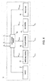
- the control unit 12 comprises a calculation module 46, at least an IGV control module 47, a fuel supplying control module 48, a cooling control module 49, a protection module 50 and a safety module 51.
- the calculation module 46 is configured to calculate at least a correction factor FC on the basis of the temperature values T1, T2... Tn detected by the plurality of heat-sensitive elements 34.
- a correction factor FC is employed in the control of the parameters of plant 1, so that the control of the parameters of plant 1 considers the distribution of temperature inside the combustion chamber 4.
- the calculation module 46 is configured to calculate a plurality of correction factors which will be employed in the control of a respective plurality of parameters of plant 1.
- control module 46 is configured to calculate the following correction factors:
- the calculation module 46 is configured to calculate the above-listed correction factors on the basis of the values T1, T2... Tn. Preferably, the calculation module 46 is configured to calculate the above-listed correction factors on the basis of a suitable function of the values T1, T2... Tn with parameters that can be regulated on the basis of the type of machine in use.
- the IGV control module 47 is configured to regulate the position IGVpos of the inlet guide vanes 16 on the basis of a reference value SPtetc of the temperature at the exhaust of turbine 5.
- the IGV control module 47 is configured to send a control signal UIGV to actuator 17.
- Normally the reference value SPtetc is generally calculated on the basis of a desired power value of plant 1 and on the basis of the ambient conditions.
- the correction factor FCtetc calculated by the calculation module 46 is greater or less than a threshold value
- the reference value SPtetc is corrected by applying the correction factor FCtetc, which is in turn a function of the temperature values T1, T2... Tn detected by the plurality of heat-sensitive elements 34.
- the fuel supplying control module 48 is configured to regulate the position of the pilot regulating valve 39 on the basis of a reference value SPpilot of the valve position such as to supply a desired pilot fuel flow rate.
- the reference value SPpilot of the valve position is corrected by applying the correction factor of the pilot flow rate set point FCpilot, which is in turn a function of the temperature values T1, T2... Tn detected by the plurality of heat-sensitive elements 34.
- the cooling control module 49 is configured to regulate the opening of the cooling regulating valve 44 on the basis of a reference value SPcool of the valve position such as to draw a desired pilot air flow rate from compressor 3.
- the reference value SPcool of the position of the cooling regulating valve 44 is corrected by applying the correction factor of the position of the cooling regulating valve FCcool, which is in turn a function of the temperature values T1, T2... Tn detected by the plurality of heat-sensitive elements 34.
- the protection module 50 is configured to change the reference power value SPpower normally used to operate plant 1 so as to prevent the gas turbine 5 from being subjected to sudden service interruptions due to combustion instability.
- the protection module 50 is configured to subtract a function contribution of the correction factor FCpower calculated by the calculation module 46, from the power reference value SPpower.
- the safety module 51 is configured to monitor the temperature values T1, T2... Tn detected by the heat-sensitive elements 34 and give rise to an alarm signal when at least one of the temperature values exceeds a predefined threshold value Tmax.
- the plant according to the present invention comprises a plurality of heat-sensitive elements 34 which are capable of monitoring the flame conditions inside the combustion chamber 4.
- the values collected by the heat-sensitive elements 34 which are conveniently processed according to a suitable function, allow the control of plant 1 by the control unit 12, to be made more efficient.
- control unit 12 Due to the fact that the control unit 12 considers the temperature profile in the combustion chamber 4 to regulate at least a parameter of plant 1, plant 1 is more reliable and performing. Indeed, the guarantee of increased combustion stability allows the gas turbine assembly to be operated more efficiently and with increased performance both at intermediate and low loads. In addition, it is possible to increase the flexibility of the plant both in terms of managing the variability of gas composition and of the opportunity to increase the variation gradient of the load delivered. When combined, these effects generate increased plant profitability and, accordingly, a significant economic benefit for clients.
Landscapes
- Engineering & Computer Science (AREA)
- Chemical & Material Sciences (AREA)
- Combustion & Propulsion (AREA)
- Mechanical Engineering (AREA)
- General Engineering & Computer Science (AREA)
- Control Of Turbines (AREA)
- Turbine Rotor Nozzle Sealing (AREA)
- Engine Equipment That Uses Special Cycles (AREA)
- Control Of Positive-Displacement Air Blowers (AREA)
Claims (21)
- Gasturbinenanlage (1) zur Erzeugung elektrischer Energie bestehend aus:einer Gasturbine (5);einem Verdichter (3);einer Brennkammer (4) mit einem Gehäuse (20), das einen Bereich definiert, in dem die Verbrennung stattfindet, und das mit einer inneren Beschichtung (21) versehen ist, die durch eine Vielzahl von Platten (22) definiert ist, die mit dem Gehäuse (20) mittels Verbindungselementen (28) verbunden sind;eine Vielzahl von wärmeempfindlichen Elementen (34), die so konfiguriert sind, dass sie eine Vielzahl von Temperaturwerten (T (1), T (2) ... Tn) innerhalb der Brennkammer (4) erfassen;einer Steuereinheit (12), die so konfiguriert ist, dass sie mindestens einen ersten Parameter (PILOTpos; IGVpos; COOLpos; SPpower) der Anlage (1) auf der Basis der Temperaturwerte (T1, T2 ... Tn) regelt, die von der Vielzahl wärmeempfindlicher Elemente (34) erfasst werden;wobei die Brennkammer (4) eine im Wesentlichen ringförmige Form aufweist;wobei die wärmeempfindlichen Elemente (34) entlang mindestens eines Teils einer oder mehrerer Erzeugenden der toroidförmigen Brennkammer (4) angeordnet und mit mindestens einem Kopplungselement (28) gekoppelt sind.
- Anlage nach Anspruch 1, wobei die wärmeempfindlichen Elemente (34) entlang der Wände der Brennkammer (4) angeordnet sind.
- Anlage nach einem der vorstehenden Ansprüche, wobei jedes Kopplungselement (28) aufweist eine Platte (30), die im Gebrauch am Gehäuse (20) befestigt ist, und eine Rippe (32), die im Gebrauch in eine entsprechende Nut (24) der Platte (22) eingreift; wobei die wärmeempfindlichen Elemente (34) mit mindestens einer Rippe (32) des entsprechenden Kopplungselements (28) verbunden sind.
- Anlage nach einem der vorstehenden Ansprüche, wobei der Kompressor (3) eine Einlaßstufe (15) umfaßt, die mit einer Vielzahl von Einlaßleitschaufeln (16) versehen ist; wobei die Steuereinheit (12) so konfiguriert ist, daß sie zumindest die Position (IGVpos) der Einlaßleitschaufeln (16) auf der Grundlage der von der Vielzahl wärmeempfindlicher Elemente (34) erfaßten Temperaturwerte (T1, T2 ... Tn) regelt.
- Anlage nach Anspruch 4, wobei die Steuereinheit (12) so konfiguriert ist, dass sie die Position (IGVpos) der Einlassleitschaufeln (16) auf der Basis eines ersten Referenzwertes (SPtetc) der Temperatur am Auslass der Turbine (5) regelt; wobei die Steuereinheit (12) so konfiguriert ist, dass sie den ersten Referenzwert (SPtetc) durch Anwendung eines ersten Korrekturfaktors (FCtetc) korrigiert, der auf der Basis der von den wärmeempfindlichen Elementen (34) erfassten Temperaturwerte (T1, T2 ... Tn) berechnet wird.
- Anlage nach einer der vorstehenden Ansprüche, bei der die Brennkammer (4) mit einem Brennstoffzufuhrkreislauf (36) versehen ist, der mit einer Pilotzufuhrleitung (37) und einem Pilotregelventil (39) versehen ist, dessen Position den Pilotbrennstoffdurchsatz regelt, die der Brennkammer (4) zugeführt wird; wobei die Steuereinheit (12) so konfiguriert ist, dass sie zumindest die Position (PILOTpos) des Pilotregelventils (39) auf der Grundlage der Temperaturwerte (T1, T2 ... Tn) regelt, die von der Vielzahl wärmeempfindlicher Elemente (34) erfasst werden.
- Anlage nach Anspruch 6, bei der die Steuereinheit (12) so konfiguriert ist, dass sie die Position des Vorsteuerventils (39), bei der ein gewünschter Vorsteuer-Brennstoffdurchsatz der Brennkammer (4) zugeführt wird, auf der Grundlage eines zweiten Referenzwertes (SPpilot) regelt; wobei die Steuereinheit (12) so konfiguriert ist, dass sie den zweiten Referenzwert (SPpilot) durch Anwendung eines zweiten Korrekturfaktors (FCpilot) korrigiert, der auf der Grundlage der Temperaturwerte (T1, T2 ... Tn) berechnet wird, die von der Vielzahl wärmeempfindlicher Elemente (34) erfasst werden.
- Anlage nach einem der vorstehenden Ansprüche, die einen Kühlkreislauf (10) umfasst, der so konfiguriert ist, dass er Luft aus dem Kompressor (3) ansaugt und die angesaugte Luft in die Gasturbine (5) einbläst, und der mit einem Kühlregelventil (44) versehen ist, dessen Position den aus dem Kompressor (3) angesaugten Luftstrom regelt; wobei die Steuereinheit (12) so konfiguriert ist, dass sie zumindest die Position (COOLpos) des Kühlregelventils (44) auf der Grundlage der Temperaturwerte (T1, T2 ... Tn) regelt, die von der Mehrzahl von 5 wärmeempfindlichen Elementen (34) erfasst werden.
- Anlage nach Anspruch 8, bei der die Steuereinheit (12) so konfiguriert ist, dass sie die Position des Kühlungsregelventils (44) auf der Basis eines dritten Referenzwertes (SPcool) regelt, bei dem ein gewünschter Luftstrom aus dem Kompressor (3) angesaugt wird; wobei die Steuereinheit (12) so konfiguriert ist, dass sie den dritten Referenzwert (SPcool) korrigiert, indem sie einen dritten Korrekturfaktor (FCcool) anwendet, der auf der Basis der Temperaturwerte (T1, T2 ... Tn) berechnet wird, die von der Mehrzahl von wärmeempfindlichen Elementen (34) erfasst werden.
- Anlage nach einem der vorstehenden Ansprüche, wobei die Steuereinheit (12) so konfiguriert ist, dass sie einen Leistungsreferenzwert (SPpower) auf der Grundlage der von der Vielzahl wärmeempfindlicher Elemente (34) erfassten Temperaturwerte (T1, T2 ... Tn) modifiziert.
- Anlage nach einem der vorstehenden Ansprüche, wobei die Steuereinheit (12) so konfiguriert ist, dass sie die von den wärmeempfindlichen Elementen (34) erfassten Temperaturwerte (T1, T2 ... Tn) überwacht und ein Alarmsignal auslöst, wenn mindestens einer der Temperaturwerte (T1, T2 ... Tn) einen vordefinierten Grenzwert (Tmax) überschreitet.
- Verfahren zum Betreiben einer Gasturbinenanlage (1) zur Erzeugung elektrischer Energie, die mit einer Gasturbine (5), einem Kompressor (3) und einer Brennkammer (4) versehen ist; wobei die Brennkammer (4) ein Gehäuse (20) umfasst, das einen Bereich definiert, in dem die Verbrennung stattfindet, und mit einer inneren Beschichtung (21) versehen ist, die durch eine Vielzahl von Platten (22) definiert ist, die mit dem Gehäuse (20) mittels Kopplungselementen (28) gekoppelt sind; wobei das Verfahren die folgenden Schritte umfasst- Erfassen einer Vielzahl von Temperaturwerten (T1, T2 ... Tn) innerhalb der Brennkammer (4) mittels einer Vielzahl von wärmeempfindlichen Elementen (34);- Regulieren mindestens eines ersten Parameters (PILOTpos; IGVpos; COOLpos; SPpower) der Anlage (1) auf der Basis der von der Vielzahl wärmeempfindlicher Elemente (34) erfassten Temperaturwerte (T1, T2 ... Tn);wobei die Brennkammer (4) eine im wesentlichen toroidale Form hat; die wärmeempfindlichen Elemente (34) entlang mindestens eines Teils einer oder mehrerer Erzeugenden der toroidalen Brennkammer (4) angeordnet sind; und mit mindestens einem Kopplungselement (28) gekoppelt sind.
- Verfahren nach Anspruch 12, wobei die wärmeempfindlichen Elemente (34) entlang der Wände der Brennkammer (4) angeordnet sind.
- Verfahren nach Anspruch 12 oder 13, wobei der Verdichter (3) eine Einlassstufe (15) umfasst, die mit einer Vielzahl von Einlassleitschaufeln (16) versehen ist; wobei der Schritt der Regulierung mindestens eines ersten Parameters (PILOTpos; IGVpos; COOLpos; SPpower) der Anlage (1) auf der Basis der Temperaturwerte (T1, T2 .... Tn), die von der Vielzahl wärmeempfindlicher Elemente (34) erfasst werden, den Schritt des Regulierens mindestens der Position (IGVpos) der Einlassleitschaufeln (16) umfasst auf der Basis der Temperaturwerte (T1, T2 ... Tn), die von der Vielzahl wärmeempfindlicher Elemente (34) erfasst werden.
- Verfahren nach Anspruch 14, wobei der Schritt des Regulierens zumindest der Position (IGVpos) der Einlassleitschaufeln (16) die folgenden Schritte umfasst:- Regulieren der Position (IGVpos) der Einlassleitschaufeln (16) auf der Grundlage eines ersten Referenzwertes (SPtetc) der Temperatur am Auslass der Turbine (5);- Korrigieren des ersten Referenzwertes (SPtetc) durch Anwendung eines ersten Korrekturfaktors (FCtetc), der auf der Grundlage der von der Mehrzahl wärmeempfindlicher Elemente (34) erfaßten Temperaturwerte (T1, T2 ... Tn) berechnet wird.
- Verfahren nach einem der Ansprüche 12 bis 15, bei dem die Brennkammer (4) mit einem Brennstoffversorgungskreislauf (36) versehen ist, der mit einer Pilotversorgungsleitung (37) und einem Pilotregelventil (39) versehen ist, dessen Position den Pilotbrennstoffdurchsatz regelt, der der Brennkammer (4) zugeführt wird; wobei der Schritt der Regelung mindestens eines ersten Parameters (PILOTpos; IGVpos; COOLpos; SPpower) der Anlage (1) auf der Grundlage der Temperaturwerte (T1, T2 . ... Tn), die von der Vielzahl wärmeempfindlicher Elemente (34) erfaßt werden, umfassend den Schritt des Regulierens wenigstens der Position (PILOTpos) des Vorsteuerventils (39) auf der Basis der von der Vielzahl wärmeempfindlicher Elemente (34) erfaßten Temperaturwerte (T1, T2 ... Tn).
- Verfahren nach Anspruch 16, wobei der Schritt des Regulierens zumindest der Position (PILOTpos) des Vorsteuerventils (39) die folgenden Schritte umfasst:Regulieren der Position des Vorsteuerventils (39) auf der Basis eines zweiten Referenzwertes (SPpilot), bei dem eine gewünschte Vorsteuer-Kraftstoffdurchflussmenge der Brennkammer (4) zugeführt wird;Korrigieren des zweiten Referenzwertes (SPpilot) durch Anwenden eines zweiten Korrekturfaktors (FCpilot), der auf der Grundlage der von der Mehrzahl von wärmeempfindlichen Elementen (34) erfaßten Temperaturwerte (T1, T2 ... Tn) berechnet wird.
- Verfahren nach einem der Ansprüche 12 bis 17, umfassend einen Kühlkreislauf (10), der so konfiguriert ist, dass er Luft aus dem Kompressor (3) ansaugt und die angesaugte Luft in die Gasturbine (5) einbläst und mit einem Kühlungsregelventil (44) versehen ist, dessen Position den aus dem Kompressor (3) angesaugten Luftstrom regelt; wobei der Schritt der Regelung mindestens eines ersten Parameters (PILOTpos; IGVpos; COOLpos; SPpower) der Anlage (1) auf der Grundlage der Temperaturwerte (T1, T2 .... Tn), die von der Vielzahl wärmeempfindlicher Elemente (34) erfaßt werden, umfasst den Schritt des Regulierens wenigstens der Position (COOLpos) des Kühlungsregulierventils (44) auf der Basis der von der Vielzahl wärmeempfindlicher Elemente (34) erfaßten Temperaturwerte (T1, T2 ... Tn).
- Verfahren nach Anspruch 18, wobei der Schritt des Regulierens zumindest der Position (COOLpos) des Kühlungsregulierventils (44) die folgenden Schritte umfasst:- Regeln der Position des Kühlungsregelventils (44) auf der Basis eines dritten Referenzwertes (SPcool), bei dem eine gewünschte Luftdurchflussmenge aus dem Kompressor (3) entnommen wird;- Korrigieren des dritten Referenzwertes (SPcool) durch Anwendung eines dritten Korrekturfaktors (FCcool), der auf der Grundlage der von der Vielzahl wärmeempfindlicher Elemente (34) erfaßten Temperaturwerte (T1, T2 ... Tn) berechnet wird.
- Verfahren nach einem der Ansprüche 12 bis 19, umfassend den Schritt des Änderns eines Leistungsreferenzwertes (SPpower) auf der Grundlage der Temperaturwerte (T1, T2 ... Tn), die von der Vielzahl wärmeempfindlicher Elemente (34) erfaßt werden.
- Verfahren nach einem der Ansprüche 12 bis 20, umfassend den Schritt des Überwachens der Temperaturwerte (T1, T2 ... Tn), die von den wärmeempfindlichen Elementen (34) erfasst werden und ein Alarmsignal auslösen, wenn mindestens einer der Temperaturwerte (T1, T2 ... Tn) einen vordefinierten Grenzwert (T+max) überschreitet.
Applications Claiming Priority (2)
| Application Number | Priority Date | Filing Date | Title |
|---|---|---|---|
| IT000089A ITMI20130089A1 (it) | 2013-01-23 | 2013-01-23 | Impianto a turbina a gas per la produzione di energia elettrica e metodo per operare detto impianto |
| PCT/IB2014/058503 WO2014115105A1 (en) | 2013-01-23 | 2014-01-23 | Gas turbine plant for electric energy production and method for operating said plant |
Publications (2)
| Publication Number | Publication Date |
|---|---|
| EP2948660A1 EP2948660A1 (de) | 2015-12-02 |
| EP2948660B1 true EP2948660B1 (de) | 2020-08-26 |
Family
ID=47790292
Family Applications (1)
| Application Number | Title | Priority Date | Filing Date |
|---|---|---|---|
| EP14714327.5A Active EP2948660B1 (de) | 2013-01-23 | 2014-01-23 | Gasturbinenanlage zur stromerzeugung und verfahren zum betreiben dieser anlage |
Country Status (5)
| Country | Link |
|---|---|
| EP (1) | EP2948660B1 (de) |
| KR (1) | KR20150135212A (de) |
| CN (1) | CN105164389B (de) |
| IT (1) | ITMI20130089A1 (de) |
| WO (1) | WO2014115105A1 (de) |
Families Citing this family (3)
| Publication number | Priority date | Publication date | Assignee | Title |
|---|---|---|---|---|
| KR20170001104A (ko) * | 2015-06-25 | 2017-01-04 | 두산중공업 주식회사 | 진동제어를 통한 제어방법 |
| CN112983653B (zh) * | 2021-03-12 | 2022-11-01 | 山东赛马力发电设备有限公司 | 一种基于三维轴流的燃气轮机气动控制系统 |
| CN117685103B (zh) * | 2024-02-04 | 2024-05-17 | 济南中科先行燃气轮机科技有限公司 | 一种二次空气调节机构及方法 |
Family Cites Families (7)
| Publication number | Priority date | Publication date | Assignee | Title |
|---|---|---|---|---|
| JP2006517636A (ja) * | 2003-02-11 | 2006-07-27 | アルストム テクノロジー リミテッド | ガスタービン群の動作方法 |
| EP1473517A1 (de) * | 2003-04-30 | 2004-11-03 | Siemens Aktiengesellschaft | Brennkammer |
| US8240153B2 (en) * | 2008-05-14 | 2012-08-14 | General Electric Company | Method and system for controlling a set point for extracting air from a compressor to provide turbine cooling air in a gas turbine |
| JP5297114B2 (ja) * | 2008-08-06 | 2013-09-25 | 三菱重工業株式会社 | ガスタービン |
| IT1397226B1 (it) * | 2009-12-30 | 2013-01-04 | Ansaldo Energia Spa | Metodo di manutenzione di una camera di combustione di un impianto a turbina a gas. |
| EP2385233A1 (de) * | 2010-05-07 | 2011-11-09 | Alstom Technology Ltd | Verfahren zum Betreiben einer Gasturbineneinheit bezogen auf die Temperatur des Brennkammergehäuses |
| US20110296844A1 (en) * | 2010-06-02 | 2011-12-08 | General Electric Company | Gas turbine combustion system with rich premixed fuel reforming and methods of use thereof |
-
2013
- 2013-01-23 IT IT000089A patent/ITMI20130089A1/it unknown
-
2014
- 2014-01-23 EP EP14714327.5A patent/EP2948660B1/de active Active
- 2014-01-23 WO PCT/IB2014/058503 patent/WO2014115105A1/en not_active Ceased
- 2014-01-23 CN CN201480005751.0A patent/CN105164389B/zh active Active
- 2014-01-23 KR KR1020157020597A patent/KR20150135212A/ko not_active Withdrawn
Non-Patent Citations (1)
| Title |
|---|
| None * |
Also Published As
| Publication number | Publication date |
|---|---|
| WO2014115105A1 (en) | 2014-07-31 |
| ITMI20130089A1 (it) | 2014-07-24 |
| CN105164389B (zh) | 2017-10-27 |
| EP2948660A1 (de) | 2015-12-02 |
| CN105164389A (zh) | 2015-12-16 |
| KR20150135212A (ko) | 2015-12-02 |
Similar Documents
| Publication | Publication Date | Title |
|---|---|---|
| EP2685067B1 (de) | Verfahren und Anordnung zur Steuerung des Pumpens einer Gasturbine | |
| CN101333966B (zh) | 多分管型燃烧室使用燃烧动态调谐算法的系统和方法 | |
| EP2738371A2 (de) | System und Verfahren zum Betreiben einer Gasturbine in Teillastmodus | |
| US20170081981A1 (en) | Method and apparatus for controlling moisture separator reheater | |
| CN102549342B (zh) | 燃烧设备 | |
| US10006315B2 (en) | System and method for improved control of a combined cycle power plant | |
| EP2085588B1 (de) | Einlassluftheizsteuervorrichtung für gasturbine | |
| US8739551B2 (en) | Method for operating a gas turbine engine by controlling the compressor discharge pressure | |
| EP3447379B1 (de) | Verfahren zum betrieb einer gasturbinenanlage und gasturbinenanlage | |
| JP2009287554A6 (ja) | ガスタービンの運転方法 | |
| CN103206269B (zh) | 用于大型蒸汽涡轮的启动方法 | |
| WO2014115105A1 (en) | Gas turbine plant for electric energy production and method for operating said plant | |
| EP3017252B1 (de) | Ziegel zur abdeckung von brennkammern, insbesondere für ein gasturbinenkraftwerk, und brennkammer mit dem besagten ziegel | |
| KR101774717B1 (ko) | 가스- 및 증기 터빈 설비의 연도 가스 덕트 내로의 물의 분무를 조절하기 위한 방법 및 장치 | |
| EP3401516B1 (de) | Kombikraftwerk, verfahren zur reduzierung der mindestausgangsleistung dafür und steuerungsvorrichtung dafür | |
| EP2827204B1 (de) | Gasturbinenmotorsteuerung mit Ereignisauslöser | |
| US9322333B2 (en) | System and method for determining a cooling flow parameter downstream from a gas turbine combustor | |
| US20180142625A1 (en) | Systems and methods for reducing airflow imbalances in turbines | |
| EP3063392B1 (de) | Steuerungsverfahren und vorrichtung zur steuerung einer gasturbinenanlage zur stromerzeugung | |
| EP3358145B1 (de) | Systeme und verfahren zur steuerung von maschinenbelastungen über temperaturtrajektorie | |
| EP2507517B2 (de) | Verfahren zur steuerung einer verbundvorrichtung und verbundvorrichtung zur anwendung dieses verfahrens | |
| EP3109551A1 (de) | Steuerungsverfahren mit schwingungskontrolle |
Legal Events
| Date | Code | Title | Description |
|---|---|---|---|
| PUAI | Public reference made under article 153(3) epc to a published international application that has entered the european phase |
Free format text: ORIGINAL CODE: 0009012 |
|
| 17P | Request for examination filed |
Effective date: 20150731 |
|
| AK | Designated contracting states |
Kind code of ref document: A1 Designated state(s): AL AT BE BG CH CY CZ DE DK EE ES FI FR GB GR HR HU IE IS IT LI LT LU LV MC MK MT NL NO PL PT RO RS SE SI SK SM TR |
|
| AX | Request for extension of the european patent |
Extension state: BA ME |
|
| RIN1 | Information on inventor provided before grant (corrected) |
Inventor name: RATTO, CHRISTIAN Inventor name: FUCILE, GIUSEPPE Inventor name: ZITO, DOMENICO Inventor name: MANTERO, MARCO |
|
| DAX | Request for extension of the european patent (deleted) | ||
| STAA | Information on the status of an ep patent application or granted ep patent |
Free format text: STATUS: EXAMINATION IS IN PROGRESS |
|
| 17Q | First examination report despatched |
Effective date: 20190729 |
|
| GRAP | Despatch of communication of intention to grant a patent |
Free format text: ORIGINAL CODE: EPIDOSNIGR1 |
|
| STAA | Information on the status of an ep patent application or granted ep patent |
Free format text: STATUS: GRANT OF PATENT IS INTENDED |
|
| INTG | Intention to grant announced |
Effective date: 20200319 |
|
| GRAS | Grant fee paid |
Free format text: ORIGINAL CODE: EPIDOSNIGR3 |
|
| GRAA | (expected) grant |
Free format text: ORIGINAL CODE: 0009210 |
|
| STAA | Information on the status of an ep patent application or granted ep patent |
Free format text: STATUS: THE PATENT HAS BEEN GRANTED |
|
| AK | Designated contracting states |
Kind code of ref document: B1 Designated state(s): AL AT BE BG CH CY CZ DE DK EE ES FI FR GB GR HR HU IE IS IT LI LT LU LV MC MK MT NL NO PL PT RO RS SE SI SK SM TR |
|
| REG | Reference to a national code |
Ref country code: GB Ref legal event code: FG4D |
|
| REG | Reference to a national code |
Ref country code: CH Ref legal event code: EP |
|
| REG | Reference to a national code |
Ref country code: AT Ref legal event code: REF Ref document number: 1306590 Country of ref document: AT Kind code of ref document: T Effective date: 20200915 |
|
| REG | Reference to a national code |
Ref country code: IE Ref legal event code: FG4D |
|
| REG | Reference to a national code |
Ref country code: DE Ref legal event code: R096 Ref document number: 602014069377 Country of ref document: DE |
|
| REG | Reference to a national code |
Ref country code: LT Ref legal event code: MG4D |
|
| PG25 | Lapsed in a contracting state [announced via postgrant information from national office to epo] |
Ref country code: SE Free format text: LAPSE BECAUSE OF FAILURE TO SUBMIT A TRANSLATION OF THE DESCRIPTION OR TO PAY THE FEE WITHIN THE PRESCRIBED TIME-LIMIT Effective date: 20200826 Ref country code: BG Free format text: LAPSE BECAUSE OF FAILURE TO SUBMIT A TRANSLATION OF THE DESCRIPTION OR TO PAY THE FEE WITHIN THE PRESCRIBED TIME-LIMIT Effective date: 20201126 Ref country code: GR Free format text: LAPSE BECAUSE OF FAILURE TO SUBMIT A TRANSLATION OF THE DESCRIPTION OR TO PAY THE FEE WITHIN THE PRESCRIBED TIME-LIMIT Effective date: 20201127 Ref country code: NO Free format text: LAPSE BECAUSE OF FAILURE TO SUBMIT A TRANSLATION OF THE DESCRIPTION OR TO PAY THE FEE WITHIN THE PRESCRIBED TIME-LIMIT Effective date: 20201126 Ref country code: PT Free format text: LAPSE BECAUSE OF FAILURE TO SUBMIT A TRANSLATION OF THE DESCRIPTION OR TO PAY THE FEE WITHIN THE PRESCRIBED TIME-LIMIT Effective date: 20201228 Ref country code: LT Free format text: LAPSE BECAUSE OF FAILURE TO SUBMIT A TRANSLATION OF THE DESCRIPTION OR TO PAY THE FEE WITHIN THE PRESCRIBED TIME-LIMIT Effective date: 20200826 Ref country code: HR Free format text: LAPSE BECAUSE OF FAILURE TO SUBMIT A TRANSLATION OF THE DESCRIPTION OR TO PAY THE FEE WITHIN THE PRESCRIBED TIME-LIMIT Effective date: 20200826 Ref country code: FI Free format text: LAPSE BECAUSE OF FAILURE TO SUBMIT A TRANSLATION OF THE DESCRIPTION OR TO PAY THE FEE WITHIN THE PRESCRIBED TIME-LIMIT Effective date: 20200826 |
|
| REG | Reference to a national code |
Ref country code: NL Ref legal event code: MP Effective date: 20200826 |
|
| REG | Reference to a national code |
Ref country code: AT Ref legal event code: MK05 Ref document number: 1306590 Country of ref document: AT Kind code of ref document: T Effective date: 20200826 |
|
| PG25 | Lapsed in a contracting state [announced via postgrant information from national office to epo] |
Ref country code: IS Free format text: LAPSE BECAUSE OF FAILURE TO SUBMIT A TRANSLATION OF THE DESCRIPTION OR TO PAY THE FEE WITHIN THE PRESCRIBED TIME-LIMIT Effective date: 20201226 Ref country code: LV Free format text: LAPSE BECAUSE OF FAILURE TO SUBMIT A TRANSLATION OF THE DESCRIPTION OR TO PAY THE FEE WITHIN THE PRESCRIBED TIME-LIMIT Effective date: 20200826 Ref country code: PL Free format text: LAPSE BECAUSE OF FAILURE TO SUBMIT A TRANSLATION OF THE DESCRIPTION OR TO PAY THE FEE WITHIN THE PRESCRIBED TIME-LIMIT Effective date: 20200826 Ref country code: NL Free format text: LAPSE BECAUSE OF FAILURE TO SUBMIT A TRANSLATION OF THE DESCRIPTION OR TO PAY THE FEE WITHIN THE PRESCRIBED TIME-LIMIT Effective date: 20200826 Ref country code: RS Free format text: LAPSE BECAUSE OF FAILURE TO SUBMIT A TRANSLATION OF THE DESCRIPTION OR TO PAY THE FEE WITHIN THE PRESCRIBED TIME-LIMIT Effective date: 20200826 |
|
| PG25 | Lapsed in a contracting state [announced via postgrant information from national office to epo] |
Ref country code: RO Free format text: LAPSE BECAUSE OF FAILURE TO SUBMIT A TRANSLATION OF THE DESCRIPTION OR TO PAY THE FEE WITHIN THE PRESCRIBED TIME-LIMIT Effective date: 20200826 Ref country code: SM Free format text: LAPSE BECAUSE OF FAILURE TO SUBMIT A TRANSLATION OF THE DESCRIPTION OR TO PAY THE FEE WITHIN THE PRESCRIBED TIME-LIMIT Effective date: 20200826 Ref country code: DK Free format text: LAPSE BECAUSE OF FAILURE TO SUBMIT A TRANSLATION OF THE DESCRIPTION OR TO PAY THE FEE WITHIN THE PRESCRIBED TIME-LIMIT Effective date: 20200826 Ref country code: EE Free format text: LAPSE BECAUSE OF FAILURE TO SUBMIT A TRANSLATION OF THE DESCRIPTION OR TO PAY THE FEE WITHIN THE PRESCRIBED TIME-LIMIT Effective date: 20200826 Ref country code: CZ Free format text: LAPSE BECAUSE OF FAILURE TO SUBMIT A TRANSLATION OF THE DESCRIPTION OR TO PAY THE FEE WITHIN THE PRESCRIBED TIME-LIMIT Effective date: 20200826 |
|
| REG | Reference to a national code |
Ref country code: DE Ref legal event code: R097 Ref document number: 602014069377 Country of ref document: DE |
|
| PG25 | Lapsed in a contracting state [announced via postgrant information from national office to epo] |
Ref country code: AL Free format text: LAPSE BECAUSE OF FAILURE TO SUBMIT A TRANSLATION OF THE DESCRIPTION OR TO PAY THE FEE WITHIN THE PRESCRIBED TIME-LIMIT Effective date: 20200826 Ref country code: AT Free format text: LAPSE BECAUSE OF FAILURE TO SUBMIT A TRANSLATION OF THE DESCRIPTION OR TO PAY THE FEE WITHIN THE PRESCRIBED TIME-LIMIT Effective date: 20200826 Ref country code: ES Free format text: LAPSE BECAUSE OF FAILURE TO SUBMIT A TRANSLATION OF THE DESCRIPTION OR TO PAY THE FEE WITHIN THE PRESCRIBED TIME-LIMIT Effective date: 20200826 |
|
| PG25 | Lapsed in a contracting state [announced via postgrant information from national office to epo] |
Ref country code: SK Free format text: LAPSE BECAUSE OF FAILURE TO SUBMIT A TRANSLATION OF THE DESCRIPTION OR TO PAY THE FEE WITHIN THE PRESCRIBED TIME-LIMIT Effective date: 20200826 |
|
| PLBE | No opposition filed within time limit |
Free format text: ORIGINAL CODE: 0009261 |
|
| STAA | Information on the status of an ep patent application or granted ep patent |
Free format text: STATUS: NO OPPOSITION FILED WITHIN TIME LIMIT |
|
| PG25 | Lapsed in a contracting state [announced via postgrant information from national office to epo] |
Ref country code: IT Free format text: LAPSE BECAUSE OF FAILURE TO SUBMIT A TRANSLATION OF THE DESCRIPTION OR TO PAY THE FEE WITHIN THE PRESCRIBED TIME-LIMIT Effective date: 20200826 |
|
| 26N | No opposition filed |
Effective date: 20210527 |
|
| PG25 | Lapsed in a contracting state [announced via postgrant information from national office to epo] |
Ref country code: SI Free format text: LAPSE BECAUSE OF FAILURE TO SUBMIT A TRANSLATION OF THE DESCRIPTION OR TO PAY THE FEE WITHIN THE PRESCRIBED TIME-LIMIT Effective date: 20200826 Ref country code: MC Free format text: LAPSE BECAUSE OF FAILURE TO SUBMIT A TRANSLATION OF THE DESCRIPTION OR TO PAY THE FEE WITHIN THE PRESCRIBED TIME-LIMIT Effective date: 20200826 |
|
| REG | Reference to a national code |
Ref country code: CH Ref legal event code: PL |
|
| GBPC | Gb: european patent ceased through non-payment of renewal fee |
Effective date: 20210123 |
|
| PG25 | Lapsed in a contracting state [announced via postgrant information from national office to epo] |
Ref country code: LU Free format text: LAPSE BECAUSE OF NON-PAYMENT OF DUE FEES Effective date: 20210123 |
|
| REG | Reference to a national code |
Ref country code: BE Ref legal event code: MM Effective date: 20210131 |
|
| PG25 | Lapsed in a contracting state [announced via postgrant information from national office to epo] |
Ref country code: FR Free format text: LAPSE BECAUSE OF NON-PAYMENT OF DUE FEES Effective date: 20210131 |
|
| PG25 | Lapsed in a contracting state [announced via postgrant information from national office to epo] |
Ref country code: LI Free format text: LAPSE BECAUSE OF NON-PAYMENT OF DUE FEES Effective date: 20210131 Ref country code: CH Free format text: LAPSE BECAUSE OF NON-PAYMENT OF DUE FEES Effective date: 20210131 Ref country code: GB Free format text: LAPSE BECAUSE OF NON-PAYMENT OF DUE FEES Effective date: 20210123 |
|
| PG25 | Lapsed in a contracting state [announced via postgrant information from national office to epo] |
Ref country code: IE Free format text: LAPSE BECAUSE OF NON-PAYMENT OF DUE FEES Effective date: 20210123 |
|
| PG25 | Lapsed in a contracting state [announced via postgrant information from national office to epo] |
Ref country code: IS Free format text: LAPSE BECAUSE OF FAILURE TO SUBMIT A TRANSLATION OF THE DESCRIPTION OR TO PAY THE FEE WITHIN THE PRESCRIBED TIME-LIMIT Effective date: 20201226 |
|
| PG25 | Lapsed in a contracting state [announced via postgrant information from national office to epo] |
Ref country code: BE Free format text: LAPSE BECAUSE OF NON-PAYMENT OF DUE FEES Effective date: 20210131 |
|
| PG25 | Lapsed in a contracting state [announced via postgrant information from national office to epo] |
Ref country code: HU Free format text: LAPSE BECAUSE OF FAILURE TO SUBMIT A TRANSLATION OF THE DESCRIPTION OR TO PAY THE FEE WITHIN THE PRESCRIBED TIME-LIMIT; INVALID AB INITIO Effective date: 20140123 |
|
| PG25 | Lapsed in a contracting state [announced via postgrant information from national office to epo] |
Ref country code: CY Free format text: LAPSE BECAUSE OF FAILURE TO SUBMIT A TRANSLATION OF THE DESCRIPTION OR TO PAY THE FEE WITHIN THE PRESCRIBED TIME-LIMIT Effective date: 20200826 |
|
| PG25 | Lapsed in a contracting state [announced via postgrant information from national office to epo] |
Ref country code: MK Free format text: LAPSE BECAUSE OF FAILURE TO SUBMIT A TRANSLATION OF THE DESCRIPTION OR TO PAY THE FEE WITHIN THE PRESCRIBED TIME-LIMIT Effective date: 20200826 |
|
| P01 | Opt-out of the competence of the unified patent court (upc) registered |
Effective date: 20240430 |
|
| PG25 | Lapsed in a contracting state [announced via postgrant information from national office to epo] |
Ref country code: TR Free format text: LAPSE BECAUSE OF FAILURE TO SUBMIT A TRANSLATION OF THE DESCRIPTION OR TO PAY THE FEE WITHIN THE PRESCRIBED TIME-LIMIT Effective date: 20200826 |
|
| PG25 | Lapsed in a contracting state [announced via postgrant information from national office to epo] |
Ref country code: MT Free format text: LAPSE BECAUSE OF FAILURE TO SUBMIT A TRANSLATION OF THE DESCRIPTION OR TO PAY THE FEE WITHIN THE PRESCRIBED TIME-LIMIT Effective date: 20200826 |
|
| PGFP | Annual fee paid to national office [announced via postgrant information from national office to epo] |
Ref country code: DE Payment date: 20260120 Year of fee payment: 13 |