EP2948074B1 - Instrument chirurgical à dispositif de suivi connecté par le biais d'un circuit souple - Google Patents
Instrument chirurgical à dispositif de suivi connecté par le biais d'un circuit souple Download PDFInfo
- Publication number
- EP2948074B1 EP2948074B1 EP14706985.0A EP14706985A EP2948074B1 EP 2948074 B1 EP2948074 B1 EP 2948074B1 EP 14706985 A EP14706985 A EP 14706985A EP 2948074 B1 EP2948074 B1 EP 2948074B1
- Authority
- EP
- European Patent Office
- Prior art keywords
- flexible circuit
- circuit sheet
- base layer
- conductive traces
- surgical instrument
- Prior art date
- Legal status (The legal status is an assumption and is not a legal conclusion. Google has not performed a legal analysis and makes no representation as to the accuracy of the status listed.)
- Active
Links
- 230000000712 assembly Effects 0.000 claims description 50
- 238000000429 assembly Methods 0.000 claims description 50
- 239000000853 adhesive Substances 0.000 claims description 27
- 230000001070 adhesive effect Effects 0.000 claims description 27
- 239000000463 material Substances 0.000 claims description 19
- 238000005452 bending Methods 0.000 claims description 12
- 230000006835 compression Effects 0.000 claims description 2
- 238000007906 compression Methods 0.000 claims description 2
- 230000002093 peripheral effect Effects 0.000 claims 2
- 230000008878 coupling Effects 0.000 description 31
- 238000010168 coupling process Methods 0.000 description 31
- 238000005859 coupling reaction Methods 0.000 description 31
- 238000000034 method Methods 0.000 description 25
- RYGMFSIKBFXOCR-UHFFFAOYSA-N Copper Chemical compound [Cu] RYGMFSIKBFXOCR-UHFFFAOYSA-N 0.000 description 18
- 239000010949 copper Substances 0.000 description 18
- 229910052802 copper Inorganic materials 0.000 description 18
- 238000004804 winding Methods 0.000 description 10
- 238000003491 array Methods 0.000 description 7
- 239000000523 sample Substances 0.000 description 7
- PXHVJJICTQNCMI-UHFFFAOYSA-N Nickel Chemical compound [Ni] PXHVJJICTQNCMI-UHFFFAOYSA-N 0.000 description 6
- 239000004642 Polyimide Substances 0.000 description 6
- 239000011248 coating agent Substances 0.000 description 6
- 238000000576 coating method Methods 0.000 description 6
- 238000004891 communication Methods 0.000 description 6
- 239000012530 fluid Substances 0.000 description 6
- 229920001721 polyimide Polymers 0.000 description 6
- 238000005476 soldering Methods 0.000 description 6
- 210000003484 anatomy Anatomy 0.000 description 5
- 238000010276 construction Methods 0.000 description 5
- 230000005672 electromagnetic field Effects 0.000 description 5
- 238000003384 imaging method Methods 0.000 description 5
- 229920002614 Polyether block amide Polymers 0.000 description 4
- 239000004809 Teflon Substances 0.000 description 4
- 229920006362 Teflon® Polymers 0.000 description 4
- 239000004020 conductor Substances 0.000 description 4
- PCHJSUWPFVWCPO-UHFFFAOYSA-N gold Chemical compound [Au] PCHJSUWPFVWCPO-UHFFFAOYSA-N 0.000 description 4
- 239000010931 gold Substances 0.000 description 4
- 229910052737 gold Inorganic materials 0.000 description 4
- -1 polyethylene Polymers 0.000 description 4
- 229920001296 polysiloxane Polymers 0.000 description 4
- 239000004820 Pressure-sensitive adhesive Substances 0.000 description 3
- 230000001154 acute effect Effects 0.000 description 3
- WYTGDNHDOZPMIW-RCBQFDQVSA-N alstonine Natural products C1=CC2=C3C=CC=CC3=NC2=C2N1C[C@H]1[C@H](C)OC=C(C(=O)OC)[C@H]1C2 WYTGDNHDOZPMIW-RCBQFDQVSA-N 0.000 description 3
- 230000004323 axial length Effects 0.000 description 3
- 238000004519 manufacturing process Methods 0.000 description 3
- 229910052759 nickel Inorganic materials 0.000 description 3
- 238000004806 packaging method and process Methods 0.000 description 3
- 238000001356 surgical procedure Methods 0.000 description 3
- 229920000459 Nitrile rubber Polymers 0.000 description 2
- 239000004698 Polyethylene Substances 0.000 description 2
- 238000007796 conventional method Methods 0.000 description 2
- 238000005520 cutting process Methods 0.000 description 2
- 238000013461 design Methods 0.000 description 2
- 230000006870 function Effects 0.000 description 2
- 229920000126 latex Polymers 0.000 description 2
- 239000004816 latex Substances 0.000 description 2
- 239000007788 liquid Substances 0.000 description 2
- 239000007769 metal material Substances 0.000 description 2
- 238000005457 optimization Methods 0.000 description 2
- 229920000573 polyethylene Polymers 0.000 description 2
- 229920002635 polyurethane Polymers 0.000 description 2
- 239000004814 polyurethane Substances 0.000 description 2
- 230000008569 process Effects 0.000 description 2
- 239000000758 substrate Substances 0.000 description 2
- KKEYFWRCBNTPAC-UHFFFAOYSA-L terephthalate(2-) Chemical compound [O-]C(=O)C1=CC=C(C([O-])=O)C=C1 KKEYFWRCBNTPAC-UHFFFAOYSA-L 0.000 description 2
- 238000002560 therapeutic procedure Methods 0.000 description 2
- 229910000838 Al alloy Inorganic materials 0.000 description 1
- ZOKXTWBITQBERF-UHFFFAOYSA-N Molybdenum Chemical compound [Mo] ZOKXTWBITQBERF-UHFFFAOYSA-N 0.000 description 1
- ATJFFYVFTNAWJD-UHFFFAOYSA-N Tin Chemical compound [Sn] ATJFFYVFTNAWJD-UHFFFAOYSA-N 0.000 description 1
- RTAQQCXQSZGOHL-UHFFFAOYSA-N Titanium Chemical compound [Ti] RTAQQCXQSZGOHL-UHFFFAOYSA-N 0.000 description 1
- 230000002411 adverse Effects 0.000 description 1
- 230000004888 barrier function Effects 0.000 description 1
- 230000008901 benefit Effects 0.000 description 1
- 238000001574 biopsy Methods 0.000 description 1
- 239000000872 buffer Substances 0.000 description 1
- 238000005352 clarification Methods 0.000 description 1
- 238000010586 diagram Methods 0.000 description 1
- 230000000694 effects Effects 0.000 description 1
- 238000005516 engineering process Methods 0.000 description 1
- 239000003822 epoxy resin Substances 0.000 description 1
- 230000001815 facial effect Effects 0.000 description 1
- 238000003780 insertion Methods 0.000 description 1
- 230000037431 insertion Effects 0.000 description 1
- 239000012212 insulator Substances 0.000 description 1
- 230000003993 interaction Effects 0.000 description 1
- 238000002955 isolation Methods 0.000 description 1
- 230000007246 mechanism Effects 0.000 description 1
- 229910052751 metal Inorganic materials 0.000 description 1
- 239000002184 metal Substances 0.000 description 1
- 238000002156 mixing Methods 0.000 description 1
- 238000012986 modification Methods 0.000 description 1
- 230000004048 modification Effects 0.000 description 1
- 229910052750 molybdenum Inorganic materials 0.000 description 1
- 239000011733 molybdenum Substances 0.000 description 1
- HLXZNVUGXRDIFK-UHFFFAOYSA-N nickel titanium Chemical compound [Ti].[Ti].[Ti].[Ti].[Ti].[Ti].[Ti].[Ti].[Ti].[Ti].[Ti].[Ni].[Ni].[Ni].[Ni].[Ni].[Ni].[Ni].[Ni].[Ni].[Ni].[Ni].[Ni].[Ni].[Ni] HLXZNVUGXRDIFK-UHFFFAOYSA-N 0.000 description 1
- 229910001000 nickel titanium Inorganic materials 0.000 description 1
- 229910052758 niobium Inorganic materials 0.000 description 1
- 239000010955 niobium Substances 0.000 description 1
- GUCVJGMIXFAOAE-UHFFFAOYSA-N niobium atom Chemical compound [Nb] GUCVJGMIXFAOAE-UHFFFAOYSA-N 0.000 description 1
- 238000007747 plating Methods 0.000 description 1
- 229920000647 polyepoxide Polymers 0.000 description 1
- 238000007639 printing Methods 0.000 description 1
- 238000012545 processing Methods 0.000 description 1
- 230000009467 reduction Effects 0.000 description 1
- 230000001105 regulatory effect Effects 0.000 description 1
- 230000000717 retained effect Effects 0.000 description 1
- 230000035945 sensitivity Effects 0.000 description 1
- 229910000679 solder Inorganic materials 0.000 description 1
- 229910001220 stainless steel Inorganic materials 0.000 description 1
- 239000010935 stainless steel Substances 0.000 description 1
- 229910001256 stainless steel alloy Inorganic materials 0.000 description 1
- 229910052715 tantalum Inorganic materials 0.000 description 1
- GUVRBAGPIYLISA-UHFFFAOYSA-N tantalum atom Chemical compound [Ta] GUVRBAGPIYLISA-UHFFFAOYSA-N 0.000 description 1
- 210000003813 thumb Anatomy 0.000 description 1
- 239000010936 titanium Substances 0.000 description 1
- 229910052719 titanium Inorganic materials 0.000 description 1
- 125000000391 vinyl group Chemical group [H]C([*])=C([H])[H] 0.000 description 1
- 229920002554 vinyl polymer Polymers 0.000 description 1
Images


Classifications
-
- H—ELECTRICITY
- H05—ELECTRIC TECHNIQUES NOT OTHERWISE PROVIDED FOR
- H05K—PRINTED CIRCUITS; CASINGS OR CONSTRUCTIONAL DETAILS OF ELECTRIC APPARATUS; MANUFACTURE OF ASSEMBLAGES OF ELECTRICAL COMPONENTS
- H05K3/00—Apparatus or processes for manufacturing printed circuits
- H05K3/30—Assembling printed circuits with electric components, e.g. with resistor
- H05K3/32—Assembling printed circuits with electric components, e.g. with resistor electrically connecting electric components or wires to printed circuits
- H05K3/34—Assembling printed circuits with electric components, e.g. with resistor electrically connecting electric components or wires to printed circuits by soldering
-
- A—HUMAN NECESSITIES
- A61—MEDICAL OR VETERINARY SCIENCE; HYGIENE
- A61B—DIAGNOSIS; SURGERY; IDENTIFICATION
- A61B34/00—Computer-aided surgery; Manipulators or robots specially adapted for use in surgery
- A61B34/20—Surgical navigation systems; Devices for tracking or guiding surgical instruments, e.g. for frameless stereotaxis
-
- H—ELECTRICITY
- H05—ELECTRIC TECHNIQUES NOT OTHERWISE PROVIDED FOR
- H05K—PRINTED CIRCUITS; CASINGS OR CONSTRUCTIONAL DETAILS OF ELECTRIC APPARATUS; MANUFACTURE OF ASSEMBLAGES OF ELECTRICAL COMPONENTS
- H05K1/00—Printed circuits
- H05K1/02—Details
- H05K1/11—Printed elements for providing electric connections to or between printed circuits
- H05K1/118—Printed elements for providing electric connections to or between printed circuits specially for flexible printed circuits, e.g. using folded portions
-
- A—HUMAN NECESSITIES
- A61—MEDICAL OR VETERINARY SCIENCE; HYGIENE
- A61B—DIAGNOSIS; SURGERY; IDENTIFICATION
- A61B17/00—Surgical instruments, devices or methods, e.g. tourniquets
- A61B17/24—Surgical instruments, devices or methods, e.g. tourniquets for use in the oral cavity, larynx, bronchial passages or nose; Tongue scrapers
-
- A—HUMAN NECESSITIES
- A61—MEDICAL OR VETERINARY SCIENCE; HYGIENE
- A61B—DIAGNOSIS; SURGERY; IDENTIFICATION
- A61B17/00—Surgical instruments, devices or methods, e.g. tourniquets
- A61B2017/00831—Material properties
- A61B2017/00862—Material properties elastic or resilient
-
- A—HUMAN NECESSITIES
- A61—MEDICAL OR VETERINARY SCIENCE; HYGIENE
- A61B—DIAGNOSIS; SURGERY; IDENTIFICATION
- A61B17/00—Surgical instruments, devices or methods, e.g. tourniquets
- A61B2017/00831—Material properties
- A61B2017/00946—Material properties malleable
-
- A—HUMAN NECESSITIES
- A61—MEDICAL OR VETERINARY SCIENCE; HYGIENE
- A61B—DIAGNOSIS; SURGERY; IDENTIFICATION
- A61B34/00—Computer-aided surgery; Manipulators or robots specially adapted for use in surgery
- A61B34/20—Surgical navigation systems; Devices for tracking or guiding surgical instruments, e.g. for frameless stereotaxis
- A61B2034/2046—Tracking techniques
- A61B2034/2051—Electromagnetic tracking systems
-
- H—ELECTRICITY
- H05—ELECTRIC TECHNIQUES NOT OTHERWISE PROVIDED FOR
- H05K—PRINTED CIRCUITS; CASINGS OR CONSTRUCTIONAL DETAILS OF ELECTRIC APPARATUS; MANUFACTURE OF ASSEMBLAGES OF ELECTRICAL COMPONENTS
- H05K1/00—Printed circuits
- H05K1/02—Details
- H05K1/0213—Electrical arrangements not otherwise provided for
- H05K1/0237—High frequency adaptations
- H05K1/0245—Lay-out of balanced signal pairs, e.g. differential lines or twisted lines
-
- H—ELECTRICITY
- H05—ELECTRIC TECHNIQUES NOT OTHERWISE PROVIDED FOR
- H05K—PRINTED CIRCUITS; CASINGS OR CONSTRUCTIONAL DETAILS OF ELECTRIC APPARATUS; MANUFACTURE OF ASSEMBLAGES OF ELECTRICAL COMPONENTS
- H05K2201/00—Indexing scheme relating to printed circuits covered by H05K1/00
- H05K2201/05—Flexible printed circuits [FPCs]
- H05K2201/051—Rolled
-
- H—ELECTRICITY
- H05—ELECTRIC TECHNIQUES NOT OTHERWISE PROVIDED FOR
- H05K—PRINTED CIRCUITS; CASINGS OR CONSTRUCTIONAL DETAILS OF ELECTRIC APPARATUS; MANUFACTURE OF ASSEMBLAGES OF ELECTRICAL COMPONENTS
- H05K2201/00—Indexing scheme relating to printed circuits covered by H05K1/00
- H05K2201/05—Flexible printed circuits [FPCs]
- H05K2201/056—Folded around rigid support or component
-
- H—ELECTRICITY
- H05—ELECTRIC TECHNIQUES NOT OTHERWISE PROVIDED FOR
- H05K—PRINTED CIRCUITS; CASINGS OR CONSTRUCTIONAL DETAILS OF ELECTRIC APPARATUS; MANUFACTURE OF ASSEMBLAGES OF ELECTRICAL COMPONENTS
- H05K2201/00—Indexing scheme relating to printed circuits covered by H05K1/00
- H05K2201/09—Shape and layout
- H05K2201/09209—Shape and layout details of conductors
- H05K2201/09654—Shape and layout details of conductors covering at least two types of conductors provided for in H05K2201/09218 - H05K2201/095
- H05K2201/097—Alternating conductors, e.g. alternating different shaped pads, twisted pairs; Alternating components
-
- H—ELECTRICITY
- H05—ELECTRIC TECHNIQUES NOT OTHERWISE PROVIDED FOR
- H05K—PRINTED CIRCUITS; CASINGS OR CONSTRUCTIONAL DETAILS OF ELECTRIC APPARATUS; MANUFACTURE OF ASSEMBLAGES OF ELECTRICAL COMPONENTS
- H05K2201/00—Indexing scheme relating to printed circuits covered by H05K1/00
- H05K2201/10—Details of components or other objects attached to or integrated in a printed circuit board
- H05K2201/10227—Other objects, e.g. metallic pieces
- H05K2201/10287—Metal wires as connectors or conductors
Definitions
- the present disclosure relates generally to a flexible circuit sheet and, more particularly, a flexible circuit sheet for a surgical instrument.
- Surgical procedures can be performed on anatomies such as the human anatomy for providing a therapy to the anatomy.
- One area of surgery includes procedures performed on facial cavities of a patient such as on the ear, nose or throat (ENT).
- a surgical instrument such as a suction device may be inserted into such a cavity to perform a procedure for example.
- a therapy such as a suction procedure
- instruments have been developed that include flexible elongated portions configured to be permanently flexible. While these flexible instruments can conform to internal cavities of the anatomy, they do not retain any specific configuration, such that they are generally not suitable for certain procedures, such as an ENT suction procedure.
- tracking devices In navigation systems, instruments are provided with tracking devices. Sometimes, however, such tracking devices can be difficult to manipulate or cumbersome to couple to the instrument, especially instruments with the flexible elongated portions. For example, it can be difficult to electrically couple the tracking devices to associated lead wires relative to the flexible elongated portion. In other instances, the tracking devices can be positioned in a handle or proximal region of the instrument such that if the distal tip moves or is moved relative to the handle, the distal tip can no longer be accurately tracked.
- a surgical instrument has an elongated body portion having a proximal end and a distal end.
- the body portion has an inner diameter defining a first internal flow passage between the proximal and distal ends, and is formed from a malleable metallic material such that the body portion can be bent between the proximal and distal ends from a first configuration to a second bent configuration and maintain the bent configuration.
- a handle portion coupled to the proximal end of the body portion and including a second internal passage in fluid communication with the first internal flow passage.
- a tracking device positioned adjacent the distal end and adapted to cooperate with a navigation system to track the location of a distal tip of the instrument, and including.
- a flexible circuit is disposed around the body portion from the tracking device to the handle portion, the flexible circuit configured to conform to the bent configuration of the body portion such that they do not strain or break during bending of the body portion.
- a surgical instrument having of an elongated body portion having a proximal end and a distal end.
- a tracking device is coupled to the elongated tubular body portion adjacent to the distal end.
- the tracking device is adapted to cooperate with a navigation system and includes a flexible circuit disposed about the tubular body portion between the proximal and distal ends.
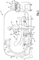
- FIG. 1 is a diagram schematically illustrating an overview of an image-guided navigation system 10 for use in the non-line-of-site navigating of a surgical instrument 100, such as a navigable malleable suction device or suction instrument, according to various exemplary embodiments of the present disclosure.
- exemplary navigation systems include those disclosed in U.S. Pat. No. 7,366,562, issued on April 29, 2008 to John H. Dukesherer et al. and U.S. Pat. App. Pub No. 2008/0132909, published June 5, 2008, to Bradley A. Jascob et al.
- Commercial navigation systems include the StealthStation® AxiEMTM Surgical Navigation System sold by Medtronic Navigation, Inc. having a place of business in Louisville, Colorado, USA. It should be appreciated that while the navigation system 10 and suction instrument 100 are generally described in connection with an ear, nose and throat (ENT) procedure, navigation system 10 and suction instrument 100 can be used in various other appropriate procedures.
- the navigation system 10 can be used to track a location of an exemplary suction instrument 100, including a distal tip or end thereof, that includes an exemplary flexible printed circuit sheet 232 associated therewith, as will be described herein.
- Navigation system 10 can generally include an optional imaging system 20, such as a fluoroscopic X-ray imaging device configured as a C-arm 24 and an image device controller 28.
- the C-arm imaging system 20 can be any appropriate imaging system, such as a digital or CCD camera, which are well understood in the art.
- Image data obtained can be stored in the C-arm controller 28 and sent to a navigation computer and/or processor controller or work station 32 having a display device 36 to display image data 40 and a user interface 44.
- the work station 32 can also include or be connected to an image processor, navigation processor, and a memory to hold instruction and data.
- the work station 32 can include an optimization processor that assists in a navigated procedure. It will also be understood that the image data is not necessarily first retained in the controller 28, but may also be directly transmitted to the workstation 32. Moreover, processing for the navigation system and optimization can all be done with a single or multiple processors all of which may or may not be included in the work station 32.
- the work station 32 provides facilities for displaying the image data 40 as an image on the display device 36, saving, digitally manipulating, or printing a hard copy image of the received image data.
- the user interface 44 which may be a keyboard, mouse, touch pen, touch screen or other suitable device, allows a physician or user 50 to provide inputs to control the imaging device 20, via the C-arm controller 28, or adjust the display settings of the display device 36.
- the navigation system 10 can further include a tracking system, such as an electromagnetic (EM) tracking system 60.
- the discussion of the EM tracking system 60 can be understood to relate to any appropriate tracking system.
- the EM tracking system 60 can include a localizer, such as a coil array 64 and/or second coil array 68, a coil array controller 72, a navigation probe interface 80, and the trackable suction instrument 100.
- Instrument 100 can include an instrument tracking device or devices 84, as will be discussed herein.
- the tracking device 84 can include an electromagnetic coil to sense a field produced by the localizing coil arrays 64, 68 and provide information to the navigation system 10 to determine a location of the tracking device 84.
- the navigation system 10 can then determine a position of a distal tip of the suction instrument 100 to allow for navigation relative to the patient 34 and patient space.
- the EM tracking system 60 can use the coil arrays 64, 68 to create an electromagnetic field used for navigation.
- the coil arrays 64, 68 can include a plurality of coils that are each operable to generate distinct electromagnetic fields into the navigation region of the patient 34, which is sometimes referred to as patient space.
- Representative electromagnetic systems are set forth in U.S. Patent No. 5,913,820 , entitled “Position Location System,” issued June 22, 1999 and U.S. Patent No. 5,592,939 , entitled “Method and System for Navigating a Catheter Probe,” issued January 14, 1997.
- the coil arrays 64, 68 can be controlled or driven by the coil array controller 72.
- the coil array controller 72 can drive each coil in the coil arrays 64, 68 in a time division multiplex or a frequency division multiplex manner. In this regard, each coil may be driven separately at a distinct time or all of the coils may be driven simultaneously with each being driven by a different frequency.
- electromagnetic fields are generated within the patient 34 in the area where the medical procedure is being performed, which is again sometimes referred to as patient space.
- the electromagnetic fields generated in the patient space induce currents in the tracking device 84 positioned on or in the suction instrument 100.
- These induced signals from the tracking device 84 can be delivered to the navigation probe interface 80 and subsequently forwarded to the processor 32.
- the navigation probe interface 80 can also include amplifiers, filters and buffers to directly interface with the tracking device 84 in the instrument 100.
- the tracking device 84, or any other appropriate portion may employ a wireless communications channel, such as that disclosed in U.S. Patent No. 6,474,341 , entitled "Surgical Communication Power System," issued November 5, 2002, as opposed to being coupled directly to the navigation probe interface 80.
- the tracking system 60 if it is using an electromagnetic tracking assembly, essentially works by positioning the coil arrays 64, 68 adjacent to the patient 32 to generate an electromagnetic field, which can be low energy, and generally referred to as a navigation field. Because every point in the navigation field or patient space is associated with a unique field strength and directions, the electromagnetic tracking system 60 can determine the position of the instrument 100 by measuring the field strength and directions or components thereof at the tracking device 84 location.
- the coil array controller 72 can receive the induced signals from the tracking device 84 and transmit information regarding a location, where location information can include both x, y, and z position and roll, pitch, and yaw orientation information, of the tracking device 84 associated with the tracked suction instrument 100. Accordingly, six degree of freedom (6 DOF) information can be determined with the navigation system 10.
- 6 DOF six degree of freedom
- the navigated malleable surgical instrument 100 can be used for suction, including fluid and tissue removal in ENT procedures. It should be appreciated, however, that the navigated malleable surgical instrument 100 can be used in various other surgical procedures as may be desired and can be provided in the form of a malleable or flexible endoscope, a malleable or flexible catheter, and/or a malleable cannula. Thus, while the following description continues with reference to a navigated malleable suction instrument 100, the discussion is also applicable to the surgical instruments discussed above.
- Suction instrument 100 can include a tube assembly 110, a handle assembly 114 and a tracking sensor arrangement 118. Suction instrument 100 can be configured for a single use such that it would be disposed after such use.
- the tube assembly 110 can include a malleable elongated tubular body 126 and an insert portion 130.
- the tubular body 126 can include an outer diameter 134 and an inner diameter 138 and can have a first end 142 coupled to the handle assembly 114 and a second opposite end 148 configured to receive insert portion 130, as shown in Figure 6 .
- the second end 148 can include an internal annular recess 152 having an inner diameter 156 greater than the inner diameter 138 of the remaining portion of body 126, as also shown in Figure 6 .
- the malleable elongated body 126 can be formed from various aluminum alloys, such as AL 3003-0, various stainless steel alloys, such as 304 annealed, as well as various other materials including titanium, niobium, molybdenum, tantalum, nitinol, vinyl, and multi-lumen materials, such that it is malleable to facilitate being bent or formed into various configurations and retaining the bent or formed configuration, as will be discussed herein.
- the body 126 can also be provided in various lengths and diameters, including 7, 9 and 12 French diameters (2.3, 3.0 and 4.0 mm).
- the insert portion 130 can be configured to provide non-malleable support for at least the tracking sensor 84.
- Insert portion 130 can include an outer diameter 160 substantially equal to the inner diameter 156 of annular recess 152, and an inner diameter 164 substantially equal to the inner diameter 138 of malleable elongated body 126, as also shown in Figure 6 .
- the substantially equal inner diameters 138, 164 can provide for a substantially constant flow path 166 for suction. It should be appreciated, however, that the inner diameters 138, 164 can also be provided with varying dimensions.
- the insert portion 130 can also include an exemplary axial length of 10 to 15 mm, including 14 mm. Insert portion 130 can include a first end 172 and a second opposite end 176.
- Insert portion 130 can include a rigid construction to facilitate receiving and housing tracking device 84, as will be described herein. In this manner, insert portion 130 can be formed or manufactured from stainless steel or other biocompatible rigid materials such that insert portion 130 is not malleable like elongated body 126.
- the insert portion can also include an exemplary axial length of approximately 10 mm.
- Insert portion 130 can include a sleeve 190 received on an exterior thereof, as shown in Figures 5 and 6 .
- Sleeve 190 can include an inner diameter 194 substantially equal to the outer diameter of insert portion 130, and an outer diameter 198 substantially equal to the outer diameter 134 of body 126. It should be appreciated that sleeve 190 can also be configured with different diameters relative to body 126.
- Sleeve 190 can extend over a portion of insert 130 from the first end 172 of the insert portion 130 towards the second end, as shown in Figure 6 . In one exemplary configuration, sleeve 190 can extend from the first end 172 and contact the first end 142 of body 126 when the insert portion 130 is coupled to annular recess 152 of body 126.
- sleeve 190 can extend from the first end 172 of body portion 130 in a similar manner as discussed above, but can stop short of the first end 142 of body 126, as shown in Figure 6 .
- Sleeve 190 can be fixed to insert portion 130, and insert portion 130 can be fixed to annular recess 152 with an appropriate adhesive.
- Sleeve 190 can be formed of a polymeric material or other suitable materials.
- Sleeve 190 can also include a first end 220 configured to substantially align with the second end 176 of insert 130.
- the first end 220 can include a rounded or chamfered blunt distal tip or end part 222 such that it can be placed against surrounding tissue during a suction procedure without cutting or damaging such tissue.
- end part 222 can extend over insert portion 130 so as to prevent cutting or damaging tissue.
- sleeve 190 can include a plurality of flattened sections 206 configured to facilitate receiving and supporting the tracking sensor arrangement 118, as will be described herein.
- sleeve 190 can include at least three flattened sections 206 configured to attachably receive tracking device 84.
- the tracking device 84 can include three coil assemblies 214, as will be described herein.
- the three coil assemblies 214 can each include a cylindrical configuration as shown in Figures 4 and 5 , having an overall axial length of approximately 1.5 mm to 2.7 mm, an overall diameter of approximately 0.3 to 0.6 mm, and a plurality of wire windings wound along a cylindrical base to form the cylindrical configuration.
- the plurality of windings can form the coil assembly 214 having the generally uniform cylindrical configuration, as generally shown in Figure 5 .
- Each flattened section 206 can include a slot or depression 218 formed therein and configured to receive a corresponding coil assembly 214, as shown for example in Figures 5 and 6 .
- Each slot 218 can be formed in the corresponding flattened section 206 at a 35 to 75 degree angle, including a 55 degree angle, to a longitudinal axis 208 of the tube assembly 110. In one exemplary configuration, each slot 218 can be formed at a 55 degree angle to longitudinal axis 208, as shown in Figure 5 .
- Each of the three flattened sections 206 can be positioned equidistantly or 120 degrees around a circumference of sleeve 190 so that the three coil assemblies 214 are therefore likewise positioned equidistantly around the circumference of sleeve 90, as also generally shown in Figures 4-6 .
- the coil assemblies can also be coupled to the sleeve without the flattened sections 206, and can be aligned at different orientations relative to the longitudinal axis, including parallel thereto.
- the sleeve 190 can include an outer surface with a circular shape in cross-section configured to receive the coil assemblies 214.
- the coil assemblies 214 can include three coil assemblies as described above that cooperate with the navigation system 10 such that 6 DOF tracking information can be determined. It should be appreciated, however, that two coil assemblies 214 could also be used in conjunction with navigation system 10 such that 6 DOF tracking information can also be determined. In a configuration where three coil assemblies 214 are utilized, two of the three coil assemblies can be positioned at an angle relative to the longitudinal axis 208 with the third coil assembly being positioned at an angle relative to the longitudinal axis 208 or parallel thereto. The three coil assemblies 214 can also each be positioned at an angle relative to each other.
- an exemplary angle of the three coil assemblies 214 relative to the longitudinal axis 208 can be 55 degrees, which also provides for optimal packaging and spacing of the coil assemblies circumferentially around sleeve 190. It should be appreciated that while an angle of 55 degrees has been discussed, other angles could be utilized with coil assemblies 214 and instrument 100 as may be required. It should also be appreciated, as discussed above, that the coil assemblies could be positioned parallel or perpendicular to the longitudinal axis 208.
- the two coil assemblies can similarly be positioned equidistant or 180 degrees spaced around an outer perimeter of sleeve 190, as well as can each be positioned at an angle relative to each other and at an angle relative to the longitudinal axis 208 of the tube assembly 110.
- the two coil assemblies can also cooperate with navigation system 10 such that 6 DOF tracking information can be determined.
- the two coil assemblies 214 can be positioned at an angle of about 35 to 75 degrees, including about 55 degrees relative to longitudinal axis 208 of the tube assembly 210.
- Coil assemblies 214A and 214B having alternative winding configurations are illustrated operatively associated with an exemplary tubular structure 223 of an exemplary instrument.
- Coil assemblies 214A and 214B can each include an overall non-linear shape as compared to the overall cylindrical configuration of coils assemblies 214 shown in Figure 5 .
- Coil assembly 214A can include a central arcuate depression or concavity 224 such that the depression 224 has a smaller outer diameter than opposed ends 225 of the plurality of windings, as generally shown in Figure 8 .
- the winding configuration of coil assembly 214A can provide an ability to maximize an amount of coil windings on a base wire while working towards minimizing an overall outer dimension or size of an instrument.
- coil assembly 214A is shown in Figure 8 with the arcuate depression 224 substantially conforming to an outer surface 226 of the tubular structure 223 such that the coil assembly or assemblies 214A essentially nest around the outer surface 226 of the tubular structure.
- a gap or space 221 on either end of the coil can include additional windings without effectively increasing the overall outer diameter of the entire assembly. This can allow for greater or stronger sensitivity in the navigated space.
- coil assembly 214B can include an overall arcuate convex shape 227 configured to conform to and nest within an inner diameter 229 of the exemplary tubular structure. Similar to coil assembly 214A, such a configuration can provide for maximizing an amount of windings on the base wire while also working towards minimizing the inner diameter 229 of the tubular structure 223 that would be required to receive one or more coil assemblies 214B.
- Tracking sensor arrangement 118 can include the tracking device 84 having the two or three coil assemblies 214, as well as a first set of lead wires 228, the flexible printed circuit board or sheet 232 and a second set of lead wires 236.
- the first set of lead wires 228 can include a pair of lead wires 228A and 228B for each coil assembly 214, as generally shown in Figure 5 .
- Each respective pair of lead wires 228A and 228B can be routed to a first end of a respective pair of circuit connections 240 on flexible printed circuit sheet 232.
- the flexible circuit sheet 232 can facilitate improving the time and cost associating with terminating fine wires utilized in medical and other instruments while also providing the flexibility necessitated for such instruments. It should be appreciated that while tracking device 84 is described as having three coil assemblies, more or less coil assemblies can be utilized as may be desired or required depending on, for example, characteristics of the navigation system being utilized as well as the number of degrees of freedom desired.
- the flexible printed circuit sheet 232 can include a flexible backing or base layer 244 such that it can readily conform to the contour of an outer surface of the body 126, as shown for example in Figure 4 .
- the flexible printed circuit sheet 232 can wrap entirely or partially around a perimeter of the body 126 and can be positioned adjacent the second end 148 of body 126, as generally shown in Figures 5 and 6 .
- the insert portion 130 in its inserted position shown in Figure 6 , can be under all or substantially all of the flexible printed circuit sheet 232.
- the rigid insert portion 130 can thus prevent the malleable body 126 from bending or flexing in a region of the flexible printed circuit sheet 232.
- the flexible printed circuit sheet 232 can be an integral part of sleeve 190.
- flexible printed circuit sheet 232 can be positioned in a similar manner on sleeve 190.
- flexible printed circuit sheet 232 can be positioned on sleeve 190 between coil assemblies 214 and the end of sleeve 190 adjacent the second end 148 of body 126.
- the second set of lead wires can include three respective pairs of wires 236A, 236B, 236C, as generally shown in Figure 5 with reference to the partial exploded view in Figure 5A .
- Figures 2-5 , 6-7 and 10 show the second set of lead wires 236 as one element, this is for illustration purposes only and it should be understood that the second set of lead wires shown in Figures 2-5 , 6-7 and 10 include the three respective pairs of lead wires 236A-C, as shown in Figure 5A .
- Each pair of lead wires 236A-C can be twisted together and positioned adjacent each other, as also shown in Figure 5A .
- the twisted pairs 236A-C of wires can reduce electrical interference or cross-talk between each pair of adjacent lead wires as well as minimize pickup from an associated electromagnetic navigation system.
- Each pair of lead wires can be connected to a single coil assembly 214 via the flexible printed circuit sheet 232.
- the lead wires can also include a Teflon coating or other appropriate lubricous or friction reducing coating on an outer surface thereof.
- Each pair of lead wires 236A-C can be coupled to an opposite end of respective circuit pads 240 on the flexible printed circuit sheet 232.
- lead wires 228 could alternatively extend up the body 126 as a twisted pair of lead wires without the use of the flexible printed circuit sheet 232, or could extend up to and be terminated directly to the respective twisted pair of lead wires 236.
- the second set of lead wires 236, which includes the three pairs of twisted wires 236A-C, can be helically wound around elongated body 126 from the flexible printed circuit sheet 232 to the second end 148, as generally shown for example in Figures 3-5A .
- the wires 236 can be wound around the outside of body 126 at an angle ⁇ relative to the longitudinal axis 208 of approximately 0 to 85 degrees, including about 30 degrees, as generally shown in Figures 5 and 5A .
- Each revolution of the wires 236 around body 126 can be spaced apart from each other by a distance D of approximately 2 to 45 mm, including about 5 mm, as shown with reference to Figure 5 .
- the range can include from about 15 - 45 mm.
- the helical winding of the wires 236 at an acute angle relative to the longitudinal axis along with the relatively close spacing of the wires and the Teflon coating facilitate being able to bend the malleable body 126 at significant angles, including beyond ninety degrees, without breaking or otherwise damaging the wires 236, as will be discussed herein.
- the wires 236 can also be positioned along body 126 in a single revolution from the flexible printed circuit sheet 232 or the tracking device 84 to the second end 148.
- the revolution spacing can be from about 2 mm to a length of the body 126.
- the wires 236 can also be positioned along body 126 from the flexible printed circuit sheet 232 to the second end 148 without being wound around body 126.
- the wires can be routed into slots 254 in handle assembly 114 and connected to respective lead wires of a cable connector assembly 258, as generally shown in Figure 7 .
- the cable connector assembly 258 can be connected to the navigation probe interface 80, as generally shown in Figure 1 .
- the handle assemble 114 can include two half sections 264, with one half section being shown in Figure 7 for illustration purposes.
- the tube assembly 110 can include a polymeric outer heat shrink 272 covering the entire assembly, as shown in the cross-sectional view of Figure 6 .
- the heat shrink 272 can cover the elongated body 126, the insert portion 130, and the sensor arrangement 118 including the wires helically wound along the body 126.
- the heat shrink 272 can provide an outer covering or shell over the tube assembly 110 and sensor arrangement 118 while providing sufficient flexibility for both bending of the body 126 and slight relative movement of the helically wound wires 236 as a result of the bending.
- the wires can be moveably captured between the heat shrink and the tubular body.
- the heat shrink covering can also serve as an electric isolation barrier. It should be appreciated that while the heat shrink covering is only shown in Figure 6 , it has not been shown in the other various views for clarification purposes only to better illustrate the sensor arrangement 118 and routing of wires 236. In this regard, it should be understood that the heat shrink 272 can cover the tube assembly 110 and sensor arrangement 118 shown in Figures 2-10 .
- the handle assembly 114 can include multiple components, such as for example two halves, with one of the halves shown in Figure 7 receiving the first end of the suction tube assembly 110 in fluid communication with a suction passage 280 formed therein.
- the suction passage 280 can terminate at a connector 284 protruding from a proximal end of the handle ( Figures 2 and 3 ) and can be configured to receive a suction hose or other arrangement in fluid communication with a suction source (not shown).
- the other half of handle assembly 114 can connected and an adhesive can be used to bond the handle halves together to form the handle as shown in Figures 2 and 3 .
- handle assembly 114 can include a suction adjustment feature 290 which can be in the form of a bore 292 extending from an outer surface 294 of the handle assembly 114 and into fluid communication with the suction passage 280.
- a surgeon or user 50 of the instrument 100 can place their thumb or another object over the bore 292 to vary an opening of the bore 292 and thus vary an amount of suction pressure realized in the flow path or passage 166. For example, if the bore 292 is left completely open or uncovered, a majority if not all of the suction will be through the bore 292 and not the first end 172 of insert portion 130.
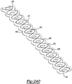
- the malleable elongated body 126 can be bent into various configurations, as generally shown by the exemplary configurations 300A-D.
- the malleable nature of body 126 can provide the ability for body 126 to be bent into such various configurations without kinking and can maintain the various configurations until bent or shaped into another configuration.
- malleable body 126 can be bent or shaped as discussed above without require additional tools, such as a mandrel to facilitate the bending. This is advantageous, for example, in that a surgeon can bend body 126 multiple times by hand during a procedure in close proximity to the patient without having to resort to additional tools or other equipment to facilitate the bending while performing the procedure.
- the helically wound configuration of wires 236 along with the Teflon coating provides for the ability to bend malleable body 126 at various angles including through ninety degrees without breaking the wires. More specifically, by winding wires 236 helically around body 126 at an angle relative to the longitudinal axis and at a close proximity to each other, the wound wires can conform to the bent shape and move or flex axially with the bent tube such that they do not strain and/or break during the bending.
- the Teflon coating provides added lubricity for the wires to have relative motion between the tube and the outer shrink coating 272 during bending.
- the distal tip 222 of the suction instrument can be tracked to provide substantially accurate position data for the distal tip of suction instrument 100 when out of a line of sight in a body cavity of patient 34.
- This is particularly useful for the malleable suction instrument 100 because, for example, the tip can be bent or moved relative to the handle and still be tracked.
- the tracking device was in the handle (such as in a hind tracked system) and the body 126 was subsequently bent or shaped, the navigation system would no longer be able to accurately track the position of the distal tip.
- the present teaching provide a tip tracked malleable suction instrument that can be bent or shaped into various configurations as may be required during a procedure, and the distal tip can be accurately tracked in any of the various bent positions.
- the patient 34 can be positioned on an operating table or other appropriate structure and appropriate image data of a patient or navigation space can be obtained, such as an ENT area.
- the image data can be registered to the navigation space as is known in the art.
- the surgeon 50 can determine a shape of the malleable suction instrument 100 to reach a target site and bend the suction instrument 100 to the determined shape where instrument 100 retains the bent shape, as discussed above.
- the bent or shaped surgical instrument 100 can then be guided to the target site with crosshairs representing the position of the distal tip of instrument 100 being superimposed on the image data.
- the crosshairs can show the tracked relative position of the distal tip as instrument 100 is navigated to the target site.
- the surgeon determines that the shaped configuration will need to be altered, the surgeon can bend and/or reshape the instrument 100 to a newly shaped configuration and proceed again as discussed above.
- tracking device 84' can include two or three wrapped coil assemblies 214' that can be used in place of the coil assemblies 214.
- Coil assemblies 214' can be wrapped around sleeve 190 proximate the distal tip 222.
- the coil assemblies 214' can be individually wrapped around sleeve 190 in an overlapping manner with a wrap axis having a non-normal and non-parallel angle to longitudinal axis 208.
- coil assemblies 214' can be wrapped around sleeve 190 at an angle relative to each other and longitudinal axis 208.
- coil assemblies 214' can be wrapped around sleeve 190 and spaced axially apart from each other.
- a further discussion of the coil assemblies 214' can be found in U.S. Application Serial No. 12/770,181, filed on April 29, 2010 and entitled "Method and Apparatus for Surgical Navigation”.
- Tracking device 84" can also be used in place of tracking device 84 and can include a plurality of oval coil assemblies 214" positioned about sleeve 190 proximate distal tip 222.
- two to four coil assemblies 214" can be positioned about sleeve 190 proximate distal tip 222.
- four coil assemblies 214" can be circumferentially spaced around sleeve 190 proximate distal tip 222, and an axial coil 304 can be positioned proximally of coil assemblies 214", as shown in Figure 12 .
- two oval coil assemblies 214" can be provided with the axial coil 304.
- the two coil assemblies 214" can also include two pair of coil assemblies 214" provided with the axial coil 304.
- the coil assemblies 214" can be formed in various selected shapes, such as elliptical, circular, or oval.
- the axial coil 304 can be concentric with and wrapped around an outer surface of sleeve 190 or body 126, as shown in Figure 12 .
- a further discussion of coil assemblies 214" and axial coil 304 can be found in U.S. Application Serial No. 13/016,740, filed on January 28, 2011 and entitled "Method and Apparatus for Image-Based Navgation".
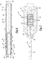
- Flexible printed circuit sheet 232 can include the flexible backing or base layer 244, one or more circuit or conductive traces, such as copper traces 350, positioned on a first or upper side 354 of base layer 244, coupling pads 358 associated with traces 350, and an insulative layer 362 formed over at least the copper traces 350 and coupled to base layer 244.
- copper traces 350 are shown positioned on upper side 354, the copper traces 350 can also be positioned on an opposite lower side of base layer 244. While the discussion will continue with reference to the conductive traces being copper traces 350, the conductive traces can also be formed from metal, nickel, gold, or copper with nickel/gold plating.
- the flexible printed circuit sheet 232 can provide a mechanism for facilitating fine gauge wire termination of associated sensors or coils and lead wires, such as wires 228 and 236 of exemplary suction instrument 100.
- the flexible printed circuit sheet 232 can also enable manufacturing and design flexibility in connection with use of circuit sheet 232 on instruments and other devices that are flexible and/or conformable.
- conventional techniques for electrically terminating sensor wires to lead wires can include directly connecting the sensor wires to the lead wires via soldering.
- soldering As can be appreciated, such a technique is very time and labor intensive considering that the sensor and lead wires can include 58 AWG wire with an outer diameter of approximately 0.01 mm.
- soldering the sensor wires to the lead wires often require performing the process under a microscope or other magnifying apparatus, which can further drive cost and expense into the manufacturing process.
- the exemplary flexible circuit sheets discussed herein can provide for improved efficiency and cost reduction in terminating such fine gauge sensor and lead wires, especially for medical instruments having size or volume constraints and that also require flexibility or conformability.
- the coupling 358 on the flexible circuit sheet 232 can be orders of magnitude bigger than the outer diameter of the wires to be terminated, such as a 0.1 mm to 0.5 mm square pad, for example.
- the coupling pads 358 can have a large surface area for the wires to be terminated such that, for example, a primary linear dimension of the coupling pads 358 can be orders of magnitude bigger than the outer diameter of the wires to be terminated.
- the wires to be terminated can include an outer diameter of between approximately 0.03 mm to 0.05 mm. In an exemplary configuration, the wires to be terminated can include 58 AWG wire having an outer diameter of approximately 0.01 mm. This can, among other things, facilitate easier and more efficient termination of the fine gauge wire due to the larger size of coupling pads 358.
- the base layer 244 can be formed form various materials having appropriate insulative properties and appropriate material properties such that base layer 244 is flexible and can conform to various surface geometries.
- the base layer 244 (as well as the assembled printed circuit sheet 232) can conform to the outer tubular surface of the malleable suction instrument 100.
- the flexible nature of flexible circuit sheet 232 can facilitate movement with tube assembly 110 of malleable instrument 100 (e.g., Figure 10 ) once adhered thereto.
- the base layer 244 can be formed from a polymeric material, including but not limited to, a polyimide.
- the base layer 244 can include a length 366 of approximately 7 mm and a width 370 of approximately 3 mm. It should be appreciated, however, that the size and shape of base layer 244 can vary depending on a particular application.
- the copper traces 350 can be positioned or printed in any desired orientation on base layer 244, including substantially perpendicular to a longitudinal axis 374 of base layer 244.
- the copper traces 350 can similarly include varying lengths and widths depending on the particular configuration of flexible printed circuit sheet 232.
- the copper traces 350 can include a length of approximately 1.25-3.0 mm and a width of approximately 0.15 mm.
- the copper traces 350 can include a thickness of approximately 0.01 - 0.04 mm.
- the coupling pads 358 can be positioned or printed at ends of the copper traces 350, as can be seen in Figures 13A-13B .
- the coupling pads 358 can be formed in any desired shape, including the square or substantially square shape 378 shown, for example, in Figures 13A-13B .
- the coupling pads 358 can also be formed to have varying dimensions, including a dimension or dimensions that is/are larger than a typical outer diameter of the wires that are to be coupled to the pads. As discussed above, such a greater dimension of the coupling pads 358 relative to the size of the wire can provide for easier soldering of the wires to the pads 358 and thus reduce time and manufacturing complexity associated with building an instrument requiring termination of fine gauge wires.
- the exemplary coupling pads 358 shown in Figures 13A-13B are square in shape and include a length and width of approximately 0.5 mm. Again, it should be appreciated that the length and width of coupling pads 358 can vary depending on the particular application of flexible printed circuit sheet 232.
- the coupling pads 358 can also be formed from copper and include a tinning material, such as tin/lead, nickel/gold and/or gold.
- the insulative layer 362 can be positioned over the copper traces 350 and coupled to the base layer 244 in any suitable manner that allows or does not inhibit the flexibility and conformability of the flexible circuit sheet 232.
- the insulative layer 362 can be adhered to the base layer 244 and copper traces 350 with an adhesive.
- the insulative layer 362 can include a shape and/or width so as to cover or substantially cover the copper traces 350 between the coupling pads 358 to insulate the traces 350 from external contact.
- the insulative layer 362 can also be formed from a polymeric material, such as polyimide.
- the insulative layer 362 can be a photoimageable coverlay.
- the insulative layer 362 can include a thickness that is less than a thickness of the base layer 244.
- the insulative layer 362 can include a rectangular shape corresponding to the exemplary symmetrical positioning of the copper traces 350 and corresponding coupling pads 358.
- an adhesive 364 can be used to couple the flexible printed circuit sheet 232 to a structure, such as the exemplary instrument 100. It should be appreciated, however, that other means for securing the flexible circuit sheet 232 to a structure can be used, so long as the means used does not inhibit the flexible nature of printed circuit sheet 232.
- the adhesive 364 can be applied to a lower or second side 384 of base layer 244. In this regard, the second side of base layer 244 can be substantially smooth. It should also be appreciated that the adhesive 364 can also be applied to the structure in addition to or in lieu of being applied to base layer 244.
- the adhesive 364 can include a medical grade pressure sensitive adhesive. In another exemplary configuration, the adhesive 364 can include a medical grade liquid or gel adhesive.
- the exemplary flexible printed circuit sheet 232 in the exemplary assembled configuration shown in Figure 13B , can include a bound together or overall thickness 388 of between approximately 0.04 - 0.07 mm. In some exemplary embodiments, the overall thickness 388 can be only approximately 0.04 mm. Stated another way, the assembled base layer 244, circuit traces and pads 350, 358 and insulative layer 263 can include an overall thickness 388 of approximately 0.05 mm. It should be appreciated, however, that such a thickness can vary to be smaller or larger depending on the particular application of the flexible printed circuit sheet 232.
- Use of the pressure sensitive adhesive 364 can increase the overall thickness 388 by approximately 0.025 mm to 0.05 mm.
- use of the gel or liquid adhesive can increase the thickness 388 by only 0.01 mm.
- the overall thickness 388 of the flexible printed circuit sheet 232 in various different configurations, can vary from 0.04 mm (without adhesive 364) to approximately 0.11 mm (with adhesive 364). As discussed above, such a minimal thickness 388 of flexible circuit sheet 232 provides for not only flexibility and conformability of the circuit sheet 232, but also applicability of the flexible circuit sheets to medical and other devices and/or instruments that have very tight volume and/or packaging constraints.
- conventional printed circuit boards considered thin in the industry can include a thickness of 0.8 mm or greater and can be made from dielectric layers laminated together with epoxy resin prepreg. Such materials combined with such a thickness do not provide for the conventional circuit boards being flexible and thus they cannot conform to non-planar surfaces and/or flex such that they cannot be used with a flexible or malleable medical instrument. Further, such a thickness of 0.8 mm or greater can preclude use of conventional printed circuit boards in medical instruments or devices where maintaining a minimum thickness or overall height is a critical parameter.
- the very thin thickness 388 of the exemplary flexible circuit sheet 232 can provide for significant flexibility and/or conformability of circuit sheet 232.
- the exemplary flexible circuit sheet 232 having the overall thickness 388 and polyimide material construction can include a bend radius of approximately ten times the thickness 388.
- the bend radius can be approximately 0.4 mm to 0.7 mm depending on the overall thickness 388 of the flexible printed circuit sheet 232.
- Such a bend radius can provide for significant flexibility in conforming the flexible printed circuit sheet to or around tight radii associated with compact or low profile medical instruments or devices.
- Flexible printed circuit sheet 232A can include similar properties and thickness dimensions as discussed above for flexible circuit sheet 232 such that like reference numerals refer to like features or components.
- Flexible printed circuit sheet 232A is shown having an exemplary custom shape 392 configured for a particular medical instrument or device.
- flexible printed circuit sheet 232A can include one or more apertures 396 configured to be positioned around and/or provide access to corresponding coil assemblies 214.
- the copper circuit traces 350 can be printed in various patterns to accommodate the apertures 396 and custom shape 392, as shown for example in Figure 14 .
- the insulative layer 362 can be custom shaped to include appropriate cutouts and an appropriate shape to cover the copper traces 350 while leaving the coupling pads 358 of flexible circuit sheet 232A exposed.
- the flexible printed circuit sheet 232A can be bent or flexed in various configurations to conform to various instrument or device shapes, such as the distal end of a malleable instrument 100.
- the flexible printed circuit sheet 232A can wrap around or substantially around the malleable suction instrument 100.
- the flexible printed circuit sheet 232A can also bend, flex or twist with the malleable suction instrument 100 during use thereof.
- the flexible printed circuit sheet 232A can flex three-dimensionally.
- flexible circuit sheet 232A can be adhered to the outer surface of a component of malleable suction instrument 100 using, for example, adhesive 364.
- the lead wires 236A can be electrically coupled, such as via soldering, to the appropriate coupling pads 358 and the coil assembly wires 228 can be soldered to the corresponding pads 358, as also shown in Figure 16 .
- flexible printed circuit sheet 232 is shown adhered to malleable suction instrument 100A, which is substantially similar to malleable suction instrument 100 shown in Figure 5 , except for channels 402 formed in sleeve 190.
- Channels 402 can receive sensor or coil wires 228 and provide a predetermined routing placement for wires 228 relative to instrument 100A, as well as position wires 228 below an outer surface 406 of sleeve 190.
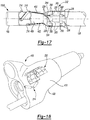
- Flexible printed circuit sheet 232 can conform to an outer surface of malleable suction instrument 100A and can provide for efficient and cost effective termination of coil assembly wires 228 and lead wires 236, as shown for example in Figure 17 .
- flexible circuit sheet 232 can be flexed to correspond to a radius of the outer surface of the instrument so as to lay substantially flush or coplanar to the outer surface.
- tracker device 410 can include the three coil assemblies 214 positioned equidistant circumferentially around a longitudinal axis 414 of tracker device 410 and can be configured to communicate with and be tracked by EM tracking system 60 of navigation system 10.
- the coil assemblies 214 can also be positioned, in the exemplary configuration illustrated, at an angle, such as between forty-five degrees and fifty-five degrees relative to axis 414 in a similar manner as coil assemblies 214 are positioned relative to instrument 100 shown in Figure 5 . It will be appreciated, however, that various other coil assembly 214 configurations and/or orientations can be utilized with patient tracker 410.
- the flexible printed circuit sheet 232 can be positioned inside of or within a body 418 of tracker 410 as shown in Figure 18 , or could alternatively be positioned on an outer surface 422 of tracker 410. In one exemplary configuration, flexible printed circuit sheet 232 can be bent or flexed to conform to the shape or contour of the surface it will be adhered to, as shown in Figure 18 . Sensor and lead wires (not shown for clarity) can be soldered to the respective circuit pads in the manner discussed above.
- Flexible printed circuit sheet 232B can be similar to flexible printed circuit sheet 232A such that like reference numerals refer to like components or features and only differences will be discussed in detail. Similar to flexible printed circuit sheet 232A, the flexible printed circuit sheet 232B can include base layer 244 having upper surface 354, conductive traces 350, solder or coupling pads 358 and top insulative layer 362.
- the flexible printed circuit sheet 232B can include one or more paired circuit traces where the pairs of circuit traces are closely spaced together, as shown for example in Figure 19 .
- the conductive traces 350 can be parallel or substantially parallel to each other and spaced apart by less than 0.3 mm, including 0.23 mm, in each pair of circuit traces.
- other spacing may be utilized depending on design and other variables.
- FIGS. 20A-20C three exemplary configurations (shown in side views) of the flexible printed circuit sheet 232B are shown. In these exemplary configurations, various different thicknesses of the flexible printed circuit sheet 232B are shown with and without adhesive, as will be discussed in greater detail below.
- flexible printed circuit sheet 232B is shown in a configuration utilizing adhesive 364.
- the base layer 244 can include a thickness of approximately 0.01 mm
- the conductive traces and pads 350, 358 can include a thickness of approximately 0.04 mm
- the insulative layer 362 can include a thickness of approximately 0.02 mm.
- the flexible printed circuit sheet 232B shown in Figure 20A can include an overall thickness 388 of approximately 0.07 mm without adhesive 364 and an overall thickness 388A of 0.11 mm with adhesive 364.
- the flexible printed circuit sheet 232B is shown having a smaller overall thickness 388 of approximately 0.05 mm without adhesive 364 and an overall thickness 388A of 0.07 mm with adhesive 364.
- the base layer 244 can similarly have a thickness of approximately 0.01 mm
- the conductive traces and pads 350, 358 can include a thickness of approximately 0.02 - 0.03 mm
- the insulative layer can include a thickness of approximately 0.01 mm.
- the flexible printed circuit sheet 232B is shown in another exemplary configuration having an overall thickness 388 of approximately 0.04 mm.
- adhesive 364 may not be utilized.
- a heat shrink layer over the flexible printed circuit sheet 232B can optionally be utilized to couple flexible printed circuit sheet 232B to an instrument, such as the suction instrument 100 discussed above.
- the base layer 244 can also include a thickness of approximately 0.01 mm
- the conductive traces and pads 350, 358 can include a thickness of approximately 0.01-0.02 mm
- the insulative layer 364 can include a thickness of approximately 0.01 mm.
- the surgical instrument 100 can be a malleable tool used for suction, including fluid and tissue removal in ENT procedures.
- the surgical instrument 100 can be a malleable tool used for suction, including fluid and tissue removal in ENT procedures.
- a flexible circuit 430 to transport electrical signals between the navigation probe interface 80 and a plurality of navigation coils 214.
- the flexible circuit 430 provides termination pads (not shown) for fine coil wires as well as cable wires and conductive traces 350 to bring electric connectivity to portions of the surgical instrument 100.
- the conductive traces 350 are configured to minimize the pickup of stray electromagnetic noise.
- the flexible circuit 430 described in detail below can be usable in other tracked medical devices or any other devices where tracking or navigating a distal tip of a device is desired.
- a navigated surgical instrument 100 the discussion is also applicable to the surgical instruments discussed above and any other appropriate instruments that require tracking or navigation of instruments that require substantially smooth exterior surfaces so as to not adversely interact with patient tissue. This is in contrast to existing instruments that have discrete wires wrapped around the outside of the instrument causing a ribbed effect.
- the flexible circuit can be used in a micro coil based core tracker assembly, slanted coil based cranial stylets, biopsy needles, or other navigated instruments requiring challenging volumetric packaging constraints.
- Surgical instrument 100 can include a tube assembly 110, a handle assembly 114, and a tracking sensor arrangement 118. Surgical instrument 100 or portions thereof can be configured for a single use such that it would be disposed of after such use.
- the tube assembly 110 can include a malleable elongated tubular body 126 and an insert portion 130.
- the malleable tubular body 126 can be formed from a malleable metallic material such that the tubular body 126 body portion can be bent between the proximal and distal ends from a first configuration to a second bent configuration and maintain the bent configuration.
- the tubular body 126 can include an outer diameter 134 and an inner diameter 138 and can have a first or proximal end 142 coupled to the handle assembly 114 and a second opposite or distal end 148 configured to receive insert portion 130.
- the second end 148 can include an internal annular recess 152 having an inner diameter 156 greater than the inner diameter 138 of the remaining portion of body 126.
- the body 126 can also be provided in various lengths and diameters including, by way of example, lengths from 50 mm - 500 mm and including 7, 9 and 12 French diameters (2.3, 3.0 and 4.0 mm).
- the insert portion 130 can be configured to provide non-malleable support for at least the tracking sensor 84.
- Insert portion 130 can include a sleeve 190 received on an exterior thereof.
- Sleeve 190 can include an inner diameter 194 substantially equal to the outer diameter of insert portion 130, and an outer diameter 198 substantially equal to the outer diameter 134 of body 126.
- the insertion of the sleeve 190 into the first end 148 of the body can facilitate the electronic coupling of tracking coils with the navigation system. Alternatively, electronic coupling can be accomplished using soldering techniques. It should be appreciated that sleeve 190 can also be configured with different diameters relative to body 126.
- Figure 22 represents a top view of conductive traces 436, 438 associated with the flexible circuit 430 of Figure 21 .
- the conductive traces 436, 438 are twisted to form loops configured to have opposite handedness from its nearest neighbors. The alternative handedness effectively cancels electromagnetic noise.
- the twisted pairs minimize electromagnetic pickup that would degrade navigation performance.
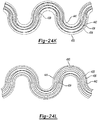
- the twisted pair configuration is formed using through-substrate or base layer 434 connections, as is illustrated exemplarily in Figure 24D on the flexible base layer 434, and provides the needed form factor.
- the flexible circuit 430 protrudes from the nominal surface radius of the body portion 126 by less than about .05 mm, thus minimizing interaction of the device with patient tissue.
- the thickness of the flex circuit is .08 mm which is less than the thickness of the twisted wires 0.4 to 0.5 mm.
- the conductive traces 436, 438 have first and second coupling pads 350 and 358 disposed at a first proximal end 142 and a second set of coupling pads 350 and 358 disposed at the second distal end 148, wherein the length of the flexible circuit 430 extending from the first proximal end 142 to the second distal end 148 is of the elongated body 126.
- the profile of the construction utilizing the flexible circuit 430 is substantially smoother and more uniform than the ribbed profile of the twisted wire configuration.
- the flexible circuit 430 having one or more, including three pairs of conductive traces 436, 438 as illustrated in Figure 22 is shown.
- the flexible circuit sheet comprises terminal pads 458.
- the flexible circuit 430 is generally disposed around the body portion 126 and extends from the tracking device 84 from the second distal end 148 to the first proximal end 142 and handle assembly 114.
- the flexible circuit is configured to conform to the bent configuration of the body portion 126 such that it does not strain or break during bending of the body portion 126.
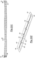
- the flexible circuit 430 can be longitudinally or helically disposed around a portion of the body portion 126 from the tracking device 84 to the handle assembly 114, the helically disposed variant not forming part of the claimed invention. If longitudinally disposed, the flexible circuit is curved transverse to the longitudinal axis of the flexible circuit 430 to conform to the curvature of the instrument shaft, as shown in Figure 23A .
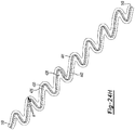
- the flexible circuit 430 can have a sinusoidal periphery or have a periphery formed of a plurality of curved line segments. If helically disposed, the flexible circuit 430 is wrapped helically around the longitudinal axis as is shown in Figure 21 .
- the flexible circuit can define gaps 433 which allow and accommodate for compression and tension of an external surface of the body portion 126.
- the gaps 433 can expand, while the inner portion during the bending of the body portion 126.
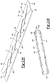
- Figure 23A represents the malleable tube 110 shown in Figure 21 .
- the flexible circuit 430 extends from the first proximal end 142 of the body portion 126 to the second distal end 148 of the body portion 126.
- a serpentine shaped flexible circuit 430 is laid longitudinally wrapped around the body portion 126.
- the conductors in the flexible circuit 430 can be generally parallel (see Figure 24F ) or form twisted pairs (See Figure 24A ) to allow the navigation system to properly account for electromagnetic noise. Each twist in the twisted pair produces a small loop to reduce electromagnetic coupling noise.
- Figure 23B represents the flexible circuit 430 in a planar manner before it has been conformed as is shown in Figure 23A .
- the serpentine shaped flexed circuit 430 when wrapped around the body portion 126, defines the gaps 433 along edges of the flexible circuit. It is envisioned the maximum radius of curvature of the body portion 126 may be regulated by the size and positions of the defined gaps 433.
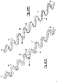
- Figures 24A-24O represent perspective views of exemplary configurations of the flexible circuit 430 according to the present teachings.
- the flexible circuit 430 has the first and second conductive traces 436, 438 which are parallel or are twisted to reduce the influence of electromagnetic noise on the tracking system.
- the flexible circuit 430 can have a base layer 434 formed of a thin insulative material such as polyimide, polyethylene, terephthalate, latex, nitrile rubber, polysiloxanes, silicone, polyurethane, polyether block amide (trade name PEBAX), a first circuit trace 436 having a first upper portion 460 of the trace formed on a first upper side 441 of the base layer 434, and a second circuit trace 438 having a second lower portion 462 formed on an second lower side 442 of the base layer 434.
- the flexible circuit 430 can take any number of shapes which allow the flexible circuit 430 and medical device to bend.
- the base layer 434 and insulative layers include material properties and a thickness configured to facilitate the flexible circuit 430 being flexible such that the flexible circuit 430 is adapted to conform to an exterior surface of the elongated body 126, as well as allow the elongated body 126 to bend along the longitudinal axis of the body portion 126.
- the flexible circuit 430 can have various components disposed between the proximal and distal ends 143, 149. In this regard, various electrical components such as amplifier or tracking coils can be attached.
- coil assemblies 214 can be coupled to the flexible circuit 430 at predetermined locations between the proximal and distal end 143, 149. In other words, a single coil assembly can be located at the second distal end 149, multiple coils can be located along the length of the flexible circuit 430.
- the conductive traces 436, 438 can form a twisted pair configuration.
- the first trace 436 runs along the first upper side 441 and crosses over a second trace 438 positioned on an opposite second side 442 at an acute angle A.
- the first trace 436 then passes through the insulator or base layer 434 and runs along the second lower side 442.
- a second trace runs along the second lower side 442 and crosses over a first trace 436 positioned on the first upper side 441 at the acute angle A.
- the first and second conductive traces 436, 438 cross from over to under at electrical vias 439.
- the vias 439 extend transversely through the base layer 434 to connect the conductive trace from the first upper side 441 to the second lower side 442.
- Figures 24B and 24C represent a flexible circuit 430 having three twisted pair configurations as shown in Figure 24A as they would be wrapped around an elongated body 126.
- coupling pads 358 are provided for coupling to the leads of three coils at the second distal end 149 or to the coupling cable wires at the first proximal end 143.
- the vias 439 are disposed between the overlapping conductive traces 436, 438 were the traces are located on opposite sides of the base layer 434. Generally, the conductive traces 436, 438 are positioned adjacent and parallel to each other to minimize conductor loop size.
- the loop area 446 can be reduced by placing the first trace 436 directly over the second trace 438 on the base layer 434 for a majority of the length of the trace except where the conductive traces separate to form vias 439 in passing areas 448. In other words, for short distances, the conductive traces separate enough to allow the traces to pass through the base layer 434 to the other side. At this point, the traces return to a position where they are parallel to each other.
- the loop area can further be reduced by reducing the thickness of the insulative base layer 434. It is envisioned the base layer 434 can have a thickness of about 0.025 mm.
- the base layer 434 can be formed of polyimide, polyethylene, terephthalate, as well as a thin elastic insulative base layer 434.
- the base layers 434 can be latex, nitrile rubber, polysiloxanes, silicone, polyurethane, polyether block amide or PEBAX.
- conductive traces 436, 438 are periodically passed through from a first upper side 441 of the base layer 434 to a second lower side 442 of the base layer 434 to form the twisted configuration.
- up to four conductive traces 436, 438 can be separated by insulative layers and run in parallel with the second pair being a twisted pair with opposite handedness to the first pair of conductive traces.
- the pair conductive traces 436, 438 need not be in a twisted pair configuration.
- Figure 24F depicts a noise minimizing parallel pair set. The configuration uses the thinness of the base layer to minimize noise.
- Figure 24G depicts a double oppositely oriented parallel pair with the second pair being a twisted pair with opposite handedness to the first pair of conductive traces.
- the proximal end 143 of the flexible circuit 430 has a pair of coupling pads 358.
- the coupling pads 358 are coupled to a pair of parallel conductive traces 436, 438 which are directly over one another, each disposed on opposing sides 441, 442 of the base layer 434.
- another pair of coupling pads 358 are provided to couple the flexible circuit to the tracking coils or tracking device 84.
- coupling pads can be found on first and second (top or bottom) sides of the base layer 434. This allows for the convenient coupling of tracking devices to the base layer 434 using soldering or connectors.
- the flexible circuits can have a sinusoidal form.
- Each conductive trace 436, 438 can be defined on a single side of the base layer 434 and can have radius of curvature R which is between the outer and inner radiuses of curvature of the base layer 434.
- the pairs of conductive traces can be formed in twisted pairs by alternating position on opposite sides of the flexible circuit as described above.
- the pair crossovers or vias 349 occur at locations along the curve. Generally, the vias 349 are positioned transverse to the longitudinal axis of the body portion 126 or base layer 434.
- the vias occur at sinusoidal midpoints wherein at Figure 24I the vias occur at sinusoidal minimums or maximums.
- the vias 349 are between peaks and valleys in the sinusoidal substrate in order to minimize the mechanical stresses on the electrical vias 349.
- the through paths or vias 349 will be formed perpendicular to the longitudinal axis of the tool.
- three pair of conductive traces can be formed on a single serpentine or sinusoidal shaped base layer 434.
- the conductor traces 436, 438 can be three pairs of conductive traces in a single serpentine flexible circuit 430.
- the position of the vias 439 can be staggered along the length of the flexible circuit so each new curvature represents a new location for the via 439.
- the vias 439 can be staggered adjacent to the centerline of the flexible circuit.
- a pair of serpentine flexible circuits 430 can be braided together to form a flat twisted pair by combining two individual sinusoidal patterned base layers 434, each with three sinusoidally patterned traces explicitly braided into three flat pairs.
- the base layers 434 can be joined at the proximal end 142 to facilitate the coupling of the tracking device 84.
- the use of several flexible circuits 430 in this configuration can provide a proper level of rigidity of the body portion 126.
- Figure 24O represents an alternate flexible circuit 430 having a braided pair configuration.
- the leads 436, 438 are disposed through the base layer and wrapped around apertures 440 defined in the base layer 344.
- the base layers 434 form the braided pair configuration and can alternate sides of the flexible circuit 430 as described above.
- the base layer 434 can include a thickness of approximately 0.01 mm
- the conductive traces 436, 438 and pads 350, 358 can include a thickness of approximately 0.04 mm
- the insulative layer 362 can include a thickness of approximately 0.02 mm.
- the flexible printed circuit sheet can include an overall thickness 388 of approximately 0.07 mm without adhesive 364 and an overall thickness 388 of 0.11 mm with adhesive 364.
- the flexible circuit 430 is shown having a smaller overall thickness 388 of approximately 0.05 mm without adhesive 364, and an overall thickness 388 of 0.07 mm with adhesive 364.
- the base layer 244 can similarly have a thickness of approximately 0.01 mm
- the conductive traces 436, 438 and pads 350, 358 can include a thickness of approximately 0.02 - 0.03 mm
- the insulative layer can include a thickness of approximately 0.01 mm.
- such a flexible printed circuit sheet could include a length configured to be helically wound from the distal end 148 to the handle assembly 114.
Landscapes
- Engineering & Computer Science (AREA)
- Health & Medical Sciences (AREA)
- Surgery (AREA)
- Microelectronics & Electronic Packaging (AREA)
- Life Sciences & Earth Sciences (AREA)
- Heart & Thoracic Surgery (AREA)
- Robotics (AREA)
- Biomedical Technology (AREA)
- Nuclear Medicine, Radiotherapy & Molecular Imaging (AREA)
- Medical Informatics (AREA)
- Molecular Biology (AREA)
- Animal Behavior & Ethology (AREA)
- General Health & Medical Sciences (AREA)
- Public Health (AREA)
- Veterinary Medicine (AREA)
- Manufacturing & Machinery (AREA)
- Surgical Instruments (AREA)
- Endoscopes (AREA)
Claims (15)
- Instrument chirurgical comprenant :un corps allongé (126) s'étendant à partir d'une extrémité proximale vers une extrémité distale ;un dispositif de suivi (84) disposé au niveau de l'extrémité distale ; etune feuille de circuit souple (430 - figure 23A) fixée au corps allongé et s'étendant à partir de l'extrémité proximale vers l'extrémité distale du corps allongé,dans lequel
la feuille de circuit souple est une première feuille de circuit souple qui a une périphérie sinusoïdale qui est disposée longitudinalement le long d'un même côté d'une partie du corps allongé et qui est courbée pour être conforme à une courbure du corps allongé ;2 la feuille de circuit souple a une couche de base (244), des première et deuxième traces conductrices (350) sur la couche de base, et une couche isolante (362) formée sur les première et deuxième traces,
la première trace et la deuxième trace sont couplées au dispositif de suivi,
la première trace et la deuxième trace s'étendent à partir de l'extrémité proximale vers l'extrémité distale, la périphérie sinusoïdale définissant des espaces (433) pour permettre et s'adapter à la compression et la tension d'une surface externe du corps allongé au cours du pliage du corps allongé. - Instrument chirurgical selon la revendication 1, dans lequel la feuille de circuit souple fait saillie à partir d'une surface du corps allongé à raison de moins de 0,08 mm.
- Instrument chirurgical selon la revendication 1 ou 2, dans lequel les première et deuxième traces conductrices comprennent une première paire de plots de borne (458) au niveau de l'extrémité proximale.
- Instrument chirurgical selon l'une quelconque des revendications 1 à 3, dans lequel les première et deuxième traces conductrices forment une paire torsadée, une double paire parallèle à orientation opposée ou une double paire torsadée à orientation opposée.
- Instrument chirurgical selon l'une quelconque des revendications 1 à 4, dans lequel la feuille de circuit souple a des caractéristiques configurées pour permettre au circuit souple de se plier, les caractéristiques étant sélectionnées dans le groupe constitué d'une forme périphérique sinusoïdale, d'une forme périphérique incurvée à base sinusoïdale, d'une couche de base formée d'un PABAX élastique, et des combinaisons de celles-ci.
- Instrument chirurgical selon l'une quelconque des revendications 1 à 5, dans lequel les première et deuxième traces conductrices ont une première partie des première et deuxième traces conductrices formée sur un premier côté de la couche de base et une seconde partie des première et deuxième traces conductrices formée sur un second côté opposé de la couche de base ;
la couche isolante étant formée sur les première et deuxième traces conductrices pour isoler les première et deuxième traces conductrices à partir d'un environnement externe, dans lequel la couche de base, les première et deuxième traces conductrices et la couche isolante forment la feuille de circuit souple ; et
dans lequel la couche de base et la couche isolante comprennent des propriétés matérielles et une épaisseur conçues pour permettre à la feuille de circuit souple d'être souple de sorte que la feuille de circuit souple est conçue pour être conforme à une surface extérieure du corps allongé. - Instrument chirurgical selon l'une quelconque des revendications 1 à 6, comprenant en outre une couche d'ajustement rétractable polymère externe recouvrant le corps allongé et la feuille de circuit souple.
- Instrument chirurgical selon l'une quelconque des revendications 1 à 7, comprenant en outre un adhésif (364) configuré pour venir en contact avec un côté inférieur de la feuille de circuit souple et conçu pour coller la feuille de circuit souple à une partie du corps allongé.
- Instrument chirurgical selon la revendication 8, dans lequel la feuille de circuit souple et l'adhésif ont une épaisseur combinée comprise entre 0,10 et 0,12 mm.
- Instrument chirurgical selon l'une quelconque des revendications 1 à 7, dans lequel une partie du corps allongé est malléable de sorte qu'elle peut être pliée en une pluralité de formes ; et
dans lequel la feuille de circuit souple est collée à une surface externe cylindrique du corps allongé et est configurée pour modifier la forme en réponse au pliage d'une partie du corps allongé. - Instrument chirurgical selon l'une quelconque des revendications 1 à 6, comprenant en outre une couche d'ajustement rétractable polymère externe recouvrant le corps allongé et la feuille de circuit souple, le circuit souple étant capturé de manière mobile entre la couche rétractable polymère externe et le corps allongé.
- Instrument chirurgical selon l'une quelconque des revendications 1 à 11, dans lequel le dispositif de suivi comprend une pluralité de bobines de suivi configurées pour se loger autour d'une surface généralement cylindrique du corps, dans lequel la pluralité de bobines de suivi comprend trois ensembles bobine ayant chacun une paire de fils conducteurs respective couplée aux traces conductrices correspondantes de la feuille de circuit souple.
- Instrument chirurgical selon la revendication 1 comprenant :le corps allongé ayant un corps tubulaire s'étendant à partir de l'extrémité proximale vers l'extrémité distale, le corps tubulaire allongé ayant un diamètre interne définissant un premier passage d'écoulement interne entre l'extrémité proximale et l'extrémité distale, et constitué d'un matériau malléable déformable de sorte que le corps tubulaire allongé peut être plié entre l'extrémité proximale et l'extrémité distale à partir d'une première configuration vers une seconde configuration pliée ;le dispositif de suivi couplé au corps tubulaire allongé adjacent à l'extrémité distale, le dispositif de suivi conçu pour coopérer avec un système de navigation pour suivre l'extrémité distale de l'instrument, le dispositif de suivi comprenant la feuille de circuit souple ayant la couche de base, les première et deuxième traces conductrices ayant chacune une première partie de la pluralité de traces conductrices formée sur un premier côté de la couche de base et une seconde partie formée sur un second côté opposé de la couche de base et une paire de fils conducteurs pour chaque ensemble bobine couplée aux traces conductrices correspondantes ; etla couche isolante formée sur les traces conductrices pour isoler les traces conductrices d'un environnement externe, la couche de base, les première et deuxième traces conductrices et la couche isolante forment la feuille de circuit souple, la couche de base et une couche isolante comprenant des propriétés matérielles et une épaisseur configurée pour permettre à la feuille de circuit souple d'être souple de sorte que la feuille de circuit souple est conçue pour être conforme à une surface externe du corps tubulaire allongé.
- Instrument chirurgical selon l'une quelconque des revendications 1 à 13, comprenant en outre une seconde feuille de circuit souple s'étendant à partir de l'extrémité proximale vers l'extrémité distale du corps allongé,
dans lequel la seconde feuille de circuit souple comprend une troisième trace et une quatrième trace, a une périphérie sinusoïdale et est tressée avec la première feuille de circuit souple. - Instrument chirurgical selon l'une quelconque des revendications 1 à 14, comprenant en outre :une première partie de la première trace qui est sur un premier côté de la couche de base,une seconde partie de la première trace qui est sur un second côté de la couche de base,une première partie de la deuxième trace qui est sur le premier côté de la couche de base, et
une seconde partie de la deuxième trace qui est sur le second côté de la couche de base.
Applications Claiming Priority (2)
| Application Number | Priority Date | Filing Date | Title |
|---|---|---|---|
| US13/751,032 US9226689B2 (en) | 2009-03-10 | 2013-01-25 | Flexible circuit sheet |
| PCT/US2014/012967 WO2014116961A1 (fr) | 2013-01-25 | 2014-01-24 | Instrument chirurgical à dispositif de suivi connecté par le biais d'un circuit souple |
Publications (2)
| Publication Number | Publication Date |
|---|---|
| EP2948074A1 EP2948074A1 (fr) | 2015-12-02 |
| EP2948074B1 true EP2948074B1 (fr) | 2018-09-19 |
Family
ID=50184998
Family Applications (1)
| Application Number | Title | Priority Date | Filing Date |
|---|---|---|---|
| EP14706985.0A Active EP2948074B1 (fr) | 2013-01-25 | 2014-01-24 | Instrument chirurgical à dispositif de suivi connecté par le biais d'un circuit souple |
Country Status (6)
| Country | Link |
|---|---|
| EP (1) | EP2948074B1 (fr) |
| JP (1) | JP6143890B2 (fr) |
| CN (1) | CN105073034B (fr) |
| AU (1) | AU2014209251B2 (fr) |
| CA (1) | CA2898636C (fr) |
| WO (1) | WO2014116961A1 (fr) |
Families Citing this family (37)
| Publication number | Priority date | Publication date | Assignee | Title |
|---|---|---|---|---|
| US11871901B2 (en) | 2012-05-20 | 2024-01-16 | Cilag Gmbh International | Method for situational awareness for surgical network or surgical network connected device capable of adjusting function based on a sensed situation or usage |
| US9101046B2 (en) * | 2013-01-29 | 2015-08-04 | Mediguide Ltd. | Shielded twisted pair of conductors using conductive ink |
| US10278729B2 (en) | 2013-04-26 | 2019-05-07 | Medtronic Xomed, Inc. | Medical device and its construction |
| US10835255B2 (en) | 2016-02-10 | 2020-11-17 | Covidien Lp | Adapter assemblies for interconnecting electromechanical handle assemblies and surgical loading units |
| US11540876B2 (en) | 2016-05-03 | 2023-01-03 | St. Jude Medical Cardiology Division, Inc. | Irrigated high density electrode catheter |
| US10799152B2 (en) * | 2016-08-11 | 2020-10-13 | Medtronic Xomed, Inc. | System and method for motion detection and accounting |
| US20180116550A1 (en) * | 2016-11-01 | 2018-05-03 | Biosense Webster (Israel) Ltd. | Rigid ENT Tool |
| US11801098B2 (en) | 2017-10-30 | 2023-10-31 | Cilag Gmbh International | Method of hub communication with surgical instrument systems |
| US11911045B2 (en) | 2017-10-30 | 2024-02-27 | Cllag GmbH International | Method for operating a powered articulating multi-clip applier |
| US11602366B2 (en) | 2017-10-30 | 2023-03-14 | Cilag Gmbh International | Surgical suturing instrument configured to manipulate tissue using mechanical and electrical power |
| US11832899B2 (en) | 2017-12-28 | 2023-12-05 | Cilag Gmbh International | Surgical systems with autonomously adjustable control programs |
| US11166772B2 (en) | 2017-12-28 | 2021-11-09 | Cilag Gmbh International | Surgical hub coordination of control and communication of operating room devices |
| US11857152B2 (en) | 2017-12-28 | 2024-01-02 | Cilag Gmbh International | Surgical hub spatial awareness to determine devices in operating theater |
| US11744604B2 (en) | 2017-12-28 | 2023-09-05 | Cilag Gmbh International | Surgical instrument with a hardware-only control circuit |
| US11132462B2 (en) | 2017-12-28 | 2021-09-28 | Cilag Gmbh International | Data stripping method to interrogate patient records and create anonymized record |
| US11844579B2 (en) | 2017-12-28 | 2023-12-19 | Cilag Gmbh International | Adjustments based on airborne particle properties |
| US11026751B2 (en) | 2017-12-28 | 2021-06-08 | Cilag Gmbh International | Display of alignment of staple cartridge to prior linear staple line |
| US11969216B2 (en) | 2017-12-28 | 2024-04-30 | Cilag Gmbh International | Surgical network recommendations from real time analysis of procedure variables against a baseline highlighting differences from the optimal solution |
| US11864728B2 (en) | 2017-12-28 | 2024-01-09 | Cilag Gmbh International | Characterization of tissue irregularities through the use of mono-chromatic light refractivity |
| US11818052B2 (en) | 2017-12-28 | 2023-11-14 | Cilag Gmbh International | Surgical network determination of prioritization of communication, interaction, or processing based on system or device needs |
| US11109866B2 (en) | 2017-12-28 | 2021-09-07 | Cilag Gmbh International | Method for circular stapler control algorithm adjustment based on situational awareness |
| US11969142B2 (en) | 2017-12-28 | 2024-04-30 | Cilag Gmbh International | Method of compressing tissue within a stapling device and simultaneously displaying the location of the tissue within the jaws |
| US20190201113A1 (en) | 2017-12-28 | 2019-07-04 | Ethicon Llc | Controls for robot-assisted surgical platforms |
| US11389164B2 (en) | 2017-12-28 | 2022-07-19 | Cilag Gmbh International | Method of using reinforced flexible circuits with multiple sensors to optimize performance of radio frequency devices |
| US11896322B2 (en) | 2017-12-28 | 2024-02-13 | Cilag Gmbh International | Sensing the patient position and contact utilizing the mono-polar return pad electrode to provide situational awareness to the hub |
| US11771487B2 (en) | 2017-12-28 | 2023-10-03 | Cilag Gmbh International | Mechanisms for controlling different electromechanical systems of an electrosurgical instrument |
| US11896443B2 (en) | 2017-12-28 | 2024-02-13 | Cilag Gmbh International | Control of a surgical system through a surgical barrier |
| EP3713493B1 (fr) * | 2018-02-14 | 2021-03-24 | St. Jude Medical International Holding S.à r.l. | Émetteur de champ magnétique localisé |
| US11986233B2 (en) | 2018-03-08 | 2024-05-21 | Cilag Gmbh International | Adjustment of complex impedance to compensate for lost power in an articulating ultrasonic device |
| US11344326B2 (en) | 2018-03-08 | 2022-05-31 | Cilag Gmbh International | Smart blade technology to control blade instability |
| US11259806B2 (en) | 2018-03-28 | 2022-03-01 | Cilag Gmbh International | Surgical stapling devices with features for blocking advancement of a camming assembly of an incompatible cartridge installed therein |
| US11090047B2 (en) | 2018-03-28 | 2021-08-17 | Cilag Gmbh International | Surgical instrument comprising an adaptive control system |
| WO2019198061A1 (fr) | 2018-04-13 | 2019-10-17 | Universidade Do Minho | Système de guidage, procédé et dispositifs associés |
| US11484366B2 (en) * | 2018-11-29 | 2022-11-01 | Acclarent, Inc. | Adapter assembly to enable navigation for ENT instruments |
| US11291444B2 (en) | 2019-02-19 | 2022-04-05 | Cilag Gmbh International | Surgical stapling assembly with cartridge based retainer configured to unlock a closure lockout |
| EP3725256B1 (fr) * | 2019-04-16 | 2023-08-30 | Stryker European Operations Limited | Suiveur de navigation chirurgicale |
| WO2024079735A1 (fr) * | 2022-10-13 | 2024-04-18 | Magnisity Ltd. | Intégration d'un circuit de composants électroniques dans un dispositif flexible allongé |
Family Cites Families (16)
| Publication number | Priority date | Publication date | Assignee | Title |
|---|---|---|---|---|
| ES2115776T3 (es) | 1992-08-14 | 1998-07-01 | British Telecomm | Sistema de localizacion de posicion. |
| US5592939A (en) | 1995-06-14 | 1997-01-14 | Martinelli; Michael A. | Method and system for navigating a catheter probe |
| JP2000151041A (ja) * | 1998-11-09 | 2000-05-30 | Yamaichi Electronics Co Ltd | プリント配線板 |
| US6474341B1 (en) | 1999-10-28 | 2002-11-05 | Surgical Navigation Technologies, Inc. | Surgical communication and power system |
| US7366562B2 (en) | 2003-10-17 | 2008-04-29 | Medtronic Navigation, Inc. | Method and apparatus for surgical navigation |
| WO2004069030A2 (fr) * | 2003-01-31 | 2004-08-19 | Verimetra, Inc. | Dispositifs medicaux et chirurgicaux munis d'un capteur integre |
| US8147486B2 (en) * | 2003-09-22 | 2012-04-03 | St. Jude Medical, Atrial Fibrillation Division, Inc. | Medical device with flexible printed circuit |
| US20090240249A1 (en) * | 2004-11-08 | 2009-09-24 | Cardima, Inc. | System and Method for Performing Ablation and Other Medical Procedures Using An Electrode Array with Flexible Circuit |
| JP4426430B2 (ja) * | 2004-12-15 | 2010-03-03 | 日東電工株式会社 | カテーテル及びその製造方法 |
| US8320991B2 (en) | 2006-12-01 | 2012-11-27 | Medtronic Navigation Inc. | Portable electromagnetic navigation system |
| US8814868B2 (en) * | 2007-02-28 | 2014-08-26 | Smith & Nephew, Inc. | Instrumented orthopaedic implant for identifying a landmark |
| CN101621966B (zh) * | 2007-02-28 | 2013-06-19 | 史密夫和内修有限公司 | 用于识别标记的系统和方法 |
| US9226688B2 (en) * | 2009-03-10 | 2016-01-05 | Medtronic Xomed, Inc. | Flexible circuit assemblies |
| US8674694B2 (en) * | 2009-08-28 | 2014-03-18 | James S. Hyde | Coil system and method for post-exposure dosimetry using electron paramagnetic resonance spectroscopy |
| EP3563788A1 (fr) * | 2010-04-30 | 2019-11-06 | Medtronic Xomed, Inc. | Instrument chirurgical malléable pilotable |
| EP2699151B1 (fr) * | 2011-04-22 | 2015-11-25 | Topera, Inc. | Cathéter de mappage cardiaque de style panier ayant des courbures de cannelure pour une détection de troubles de la fréquence cardiaque |
-
2014
- 2014-01-24 CN CN201480005951.6A patent/CN105073034B/zh active Active
- 2014-01-24 EP EP14706985.0A patent/EP2948074B1/fr active Active
- 2014-01-24 JP JP2015555346A patent/JP6143890B2/ja not_active Expired - Fee Related
- 2014-01-24 AU AU2014209251A patent/AU2014209251B2/en not_active Ceased
- 2014-01-24 CA CA2898636A patent/CA2898636C/fr active Active
- 2014-01-24 WO PCT/US2014/012967 patent/WO2014116961A1/fr active Application Filing
Non-Patent Citations (1)
| Title |
|---|
| None * |
Also Published As
| Publication number | Publication date |
|---|---|
| EP2948074A1 (fr) | 2015-12-02 |
| JP2016505344A (ja) | 2016-02-25 |
| CA2898636A1 (fr) | 2014-07-31 |
| JP6143890B2 (ja) | 2017-06-07 |
| WO2014116961A1 (fr) | 2014-07-31 |
| CA2898636C (fr) | 2021-02-16 |
| CN105073034B (zh) | 2018-04-27 |
| AU2014209251A1 (en) | 2015-08-27 |
| CN105073034A (zh) | 2015-11-18 |
| AU2014209251B2 (en) | 2018-10-25 |
Similar Documents
| Publication | Publication Date | Title |
|---|---|---|
| US20230081692A1 (en) | Flexible circuit sheet | |
| EP2948074B1 (fr) | Instrument chirurgical à dispositif de suivi connecté par le biais d'un circuit souple | |
| US9226688B2 (en) | Flexible circuit assemblies | |
| US20210000379A1 (en) | Navigated Surgical Instrument | |
| US9226800B2 (en) | Navigated malleable surgical instrument | |
| EP2948090B1 (fr) | Instrument chirurgical à navigation comprenant une feuille de circuit souple |
Legal Events
| Date | Code | Title | Description |
|---|---|---|---|
| PUAI | Public reference made under article 153(3) epc to a published international application that has entered the european phase |
Free format text: ORIGINAL CODE: 0009012 |
|
| 17P | Request for examination filed |
Effective date: 20150812 |
|
| AK | Designated contracting states |
Kind code of ref document: A1 Designated state(s): AL AT BE BG CH CY CZ DE DK EE ES FI FR GB GR HR HU IE IS IT LI LT LU LV MC MK MT NL NO PL PT RO RS SE SI SK SM TR |
|
| AX | Request for extension of the european patent |
Extension state: BA ME |
|
| DAX | Request for extension of the european patent (deleted) | ||
| STAA | Information on the status of an ep patent application or granted ep patent |
Free format text: STATUS: EXAMINATION IS IN PROGRESS |
|
| 17Q | First examination report despatched |
Effective date: 20170413 |
|
| RIC1 | Information provided on ipc code assigned before grant |
Ipc: A61B 17/24 20060101AFI20180202BHEP Ipc: H05K 1/03 20060101ALN20180202BHEP Ipc: A61B 34/20 20160101ALI20180202BHEP |
|
| GRAP | Despatch of communication of intention to grant a patent |
Free format text: ORIGINAL CODE: EPIDOSNIGR1 |
|
| STAA | Information on the status of an ep patent application or granted ep patent |
Free format text: STATUS: GRANT OF PATENT IS INTENDED |
|
| RIC1 | Information provided on ipc code assigned before grant |
Ipc: A61B 34/20 20160101ALI20180305BHEP Ipc: H05K 1/03 20060101ALN20180305BHEP Ipc: A61B 17/24 20060101AFI20180305BHEP |
|
| INTG | Intention to grant announced |
Effective date: 20180404 |
|
| GRAS | Grant fee paid |
Free format text: ORIGINAL CODE: EPIDOSNIGR3 |
|
| GRAA | (expected) grant |
Free format text: ORIGINAL CODE: 0009210 |
|
| STAA | Information on the status of an ep patent application or granted ep patent |
Free format text: STATUS: THE PATENT HAS BEEN GRANTED |
|
| AK | Designated contracting states |
Kind code of ref document: B1 Designated state(s): AL AT BE BG CH CY CZ DE DK EE ES FI FR GB GR HR HU IE IS IT LI LT LU LV MC MK MT NL NO PL PT RO RS SE SI SK SM TR |
|
| REG | Reference to a national code |
Ref country code: GB Ref legal event code: FG4D |
|
| REG | Reference to a national code |
Ref country code: CH Ref legal event code: EP |
|
| REG | Reference to a national code |
Ref country code: DE Ref legal event code: R096 Ref document number: 602014032484 Country of ref document: DE |
|
| REG | Reference to a national code |
Ref country code: AT Ref legal event code: REF Ref document number: 1042335 Country of ref document: AT Kind code of ref document: T Effective date: 20181015 |
|
| REG | Reference to a national code |
Ref country code: IE Ref legal event code: FG4D |
|
| REG | Reference to a national code |
Ref country code: NL Ref legal event code: MP Effective date: 20180919 |
|
| PG25 | Lapsed in a contracting state [announced via postgrant information from national office to epo] |
Ref country code: GR Free format text: LAPSE BECAUSE OF FAILURE TO SUBMIT A TRANSLATION OF THE DESCRIPTION OR TO PAY THE FEE WITHIN THE PRESCRIBED TIME-LIMIT Effective date: 20181220 Ref country code: RS Free format text: LAPSE BECAUSE OF FAILURE TO SUBMIT A TRANSLATION OF THE DESCRIPTION OR TO PAY THE FEE WITHIN THE PRESCRIBED TIME-LIMIT Effective date: 20180919 Ref country code: FI Free format text: LAPSE BECAUSE OF FAILURE TO SUBMIT A TRANSLATION OF THE DESCRIPTION OR TO PAY THE FEE WITHIN THE PRESCRIBED TIME-LIMIT Effective date: 20180919 Ref country code: LT Free format text: LAPSE BECAUSE OF FAILURE TO SUBMIT A TRANSLATION OF THE DESCRIPTION OR TO PAY THE FEE WITHIN THE PRESCRIBED TIME-LIMIT Effective date: 20180919 Ref country code: SE Free format text: LAPSE BECAUSE OF FAILURE TO SUBMIT A TRANSLATION OF THE DESCRIPTION OR TO PAY THE FEE WITHIN THE PRESCRIBED TIME-LIMIT Effective date: 20180919 Ref country code: NO Free format text: LAPSE BECAUSE OF FAILURE TO SUBMIT A TRANSLATION OF THE DESCRIPTION OR TO PAY THE FEE WITHIN THE PRESCRIBED TIME-LIMIT Effective date: 20181219 Ref country code: BG Free format text: LAPSE BECAUSE OF FAILURE TO SUBMIT A TRANSLATION OF THE DESCRIPTION OR TO PAY THE FEE WITHIN THE PRESCRIBED TIME-LIMIT Effective date: 20181219 |
|
| REG | Reference to a national code |
Ref country code: LT Ref legal event code: MG4D |
|
| PG25 | Lapsed in a contracting state [announced via postgrant information from national office to epo] |
Ref country code: HR Free format text: LAPSE BECAUSE OF FAILURE TO SUBMIT A TRANSLATION OF THE DESCRIPTION OR TO PAY THE FEE WITHIN THE PRESCRIBED TIME-LIMIT Effective date: 20180919 Ref country code: AL Free format text: LAPSE BECAUSE OF FAILURE TO SUBMIT A TRANSLATION OF THE DESCRIPTION OR TO PAY THE FEE WITHIN THE PRESCRIBED TIME-LIMIT Effective date: 20180919 Ref country code: LV Free format text: LAPSE BECAUSE OF FAILURE TO SUBMIT A TRANSLATION OF THE DESCRIPTION OR TO PAY THE FEE WITHIN THE PRESCRIBED TIME-LIMIT Effective date: 20180919 |
|
| REG | Reference to a national code |
Ref country code: AT Ref legal event code: MK05 Ref document number: 1042335 Country of ref document: AT Kind code of ref document: T Effective date: 20180919 |
|
| PG25 | Lapsed in a contracting state [announced via postgrant information from national office to epo] |
Ref country code: CZ Free format text: LAPSE BECAUSE OF FAILURE TO SUBMIT A TRANSLATION OF THE DESCRIPTION OR TO PAY THE FEE WITHIN THE PRESCRIBED TIME-LIMIT Effective date: 20180919 Ref country code: IT Free format text: LAPSE BECAUSE OF FAILURE TO SUBMIT A TRANSLATION OF THE DESCRIPTION OR TO PAY THE FEE WITHIN THE PRESCRIBED TIME-LIMIT Effective date: 20180919 Ref country code: ES Free format text: LAPSE BECAUSE OF FAILURE TO SUBMIT A TRANSLATION OF THE DESCRIPTION OR TO PAY THE FEE WITHIN THE PRESCRIBED TIME-LIMIT Effective date: 20180919 Ref country code: AT Free format text: LAPSE BECAUSE OF FAILURE TO SUBMIT A TRANSLATION OF THE DESCRIPTION OR TO PAY THE FEE WITHIN THE PRESCRIBED TIME-LIMIT Effective date: 20180919 Ref country code: NL Free format text: LAPSE BECAUSE OF FAILURE TO SUBMIT A TRANSLATION OF THE DESCRIPTION OR TO PAY THE FEE WITHIN THE PRESCRIBED TIME-LIMIT Effective date: 20180919 Ref country code: RO Free format text: LAPSE BECAUSE OF FAILURE TO SUBMIT A TRANSLATION OF THE DESCRIPTION OR TO PAY THE FEE WITHIN THE PRESCRIBED TIME-LIMIT Effective date: 20180919 Ref country code: PL Free format text: LAPSE BECAUSE OF FAILURE TO SUBMIT A TRANSLATION OF THE DESCRIPTION OR TO PAY THE FEE WITHIN THE PRESCRIBED TIME-LIMIT Effective date: 20180919 Ref country code: EE Free format text: LAPSE BECAUSE OF FAILURE TO SUBMIT A TRANSLATION OF THE DESCRIPTION OR TO PAY THE FEE WITHIN THE PRESCRIBED TIME-LIMIT Effective date: 20180919 Ref country code: IS Free format text: LAPSE BECAUSE OF FAILURE TO SUBMIT A TRANSLATION OF THE DESCRIPTION OR TO PAY THE FEE WITHIN THE PRESCRIBED TIME-LIMIT Effective date: 20190119 |
|
| PG25 | Lapsed in a contracting state [announced via postgrant information from national office to epo] |
Ref country code: SK Free format text: LAPSE BECAUSE OF FAILURE TO SUBMIT A TRANSLATION OF THE DESCRIPTION OR TO PAY THE FEE WITHIN THE PRESCRIBED TIME-LIMIT Effective date: 20180919 Ref country code: PT Free format text: LAPSE BECAUSE OF FAILURE TO SUBMIT A TRANSLATION OF THE DESCRIPTION OR TO PAY THE FEE WITHIN THE PRESCRIBED TIME-LIMIT Effective date: 20190119 Ref country code: SM Free format text: LAPSE BECAUSE OF FAILURE TO SUBMIT A TRANSLATION OF THE DESCRIPTION OR TO PAY THE FEE WITHIN THE PRESCRIBED TIME-LIMIT Effective date: 20180919 |
|
| REG | Reference to a national code |
Ref country code: DE Ref legal event code: R097 Ref document number: 602014032484 Country of ref document: DE |
|
| PLBE | No opposition filed within time limit |
Free format text: ORIGINAL CODE: 0009261 |
|
| STAA | Information on the status of an ep patent application or granted ep patent |
Free format text: STATUS: NO OPPOSITION FILED WITHIN TIME LIMIT |
|
| PG25 | Lapsed in a contracting state [announced via postgrant information from national office to epo] |
Ref country code: DK Free format text: LAPSE BECAUSE OF FAILURE TO SUBMIT A TRANSLATION OF THE DESCRIPTION OR TO PAY THE FEE WITHIN THE PRESCRIBED TIME-LIMIT Effective date: 20180919 |
|
| 26N | No opposition filed |
Effective date: 20190620 |
|
| PG25 | Lapsed in a contracting state [announced via postgrant information from national office to epo] |
Ref country code: MC Free format text: LAPSE BECAUSE OF FAILURE TO SUBMIT A TRANSLATION OF THE DESCRIPTION OR TO PAY THE FEE WITHIN THE PRESCRIBED TIME-LIMIT Effective date: 20180919 |
|
| REG | Reference to a national code |
Ref country code: CH Ref legal event code: PL |
|
| GBPC | Gb: european patent ceased through non-payment of renewal fee |
Effective date: 20190124 |
|
| PG25 | Lapsed in a contracting state [announced via postgrant information from national office to epo] |
Ref country code: LU Free format text: LAPSE BECAUSE OF NON-PAYMENT OF DUE FEES Effective date: 20190124 |
|
| REG | Reference to a national code |
Ref country code: BE Ref legal event code: MM Effective date: 20190131 |
|
| REG | Reference to a national code |
Ref country code: IE Ref legal event code: MM4A |
|
| PG25 | Lapsed in a contracting state [announced via postgrant information from national office to epo] |
Ref country code: SI Free format text: LAPSE BECAUSE OF FAILURE TO SUBMIT A TRANSLATION OF THE DESCRIPTION OR TO PAY THE FEE WITHIN THE PRESCRIBED TIME-LIMIT Effective date: 20180919 |
|
| PG25 | Lapsed in a contracting state [announced via postgrant information from national office to epo] |
Ref country code: BE Free format text: LAPSE BECAUSE OF NON-PAYMENT OF DUE FEES Effective date: 20190131 |
|
| PG25 | Lapsed in a contracting state [announced via postgrant information from national office to epo] |
Ref country code: GB Free format text: LAPSE BECAUSE OF NON-PAYMENT OF DUE FEES Effective date: 20190124 Ref country code: CH Free format text: LAPSE BECAUSE OF NON-PAYMENT OF DUE FEES Effective date: 20190131 Ref country code: LI Free format text: LAPSE BECAUSE OF NON-PAYMENT OF DUE FEES Effective date: 20190131 |
|
| PG25 | Lapsed in a contracting state [announced via postgrant information from national office to epo] |
Ref country code: IE Free format text: LAPSE BECAUSE OF NON-PAYMENT OF DUE FEES Effective date: 20190124 |
|
| PG25 | Lapsed in a contracting state [announced via postgrant information from national office to epo] |
Ref country code: TR Free format text: LAPSE BECAUSE OF FAILURE TO SUBMIT A TRANSLATION OF THE DESCRIPTION OR TO PAY THE FEE WITHIN THE PRESCRIBED TIME-LIMIT Effective date: 20180919 |
|
| PG25 | Lapsed in a contracting state [announced via postgrant information from national office to epo] |
Ref country code: MT Free format text: LAPSE BECAUSE OF NON-PAYMENT OF DUE FEES Effective date: 20190124 |
|
| PG25 | Lapsed in a contracting state [announced via postgrant information from national office to epo] |
Ref country code: CY Free format text: LAPSE BECAUSE OF FAILURE TO SUBMIT A TRANSLATION OF THE DESCRIPTION OR TO PAY THE FEE WITHIN THE PRESCRIBED TIME-LIMIT Effective date: 20180919 |
|
| PG25 | Lapsed in a contracting state [announced via postgrant information from national office to epo] |
Ref country code: HU Free format text: LAPSE BECAUSE OF FAILURE TO SUBMIT A TRANSLATION OF THE DESCRIPTION OR TO PAY THE FEE WITHIN THE PRESCRIBED TIME-LIMIT; INVALID AB INITIO Effective date: 20140124 |
|
| PG25 | Lapsed in a contracting state [announced via postgrant information from national office to epo] |
Ref country code: MK Free format text: LAPSE BECAUSE OF FAILURE TO SUBMIT A TRANSLATION OF THE DESCRIPTION OR TO PAY THE FEE WITHIN THE PRESCRIBED TIME-LIMIT Effective date: 20180919 |
|
| PGFP | Annual fee paid to national office [announced via postgrant information from national office to epo] |
Ref country code: FR Payment date: 20231219 Year of fee payment: 11 |
|
| PGFP | Annual fee paid to national office [announced via postgrant information from national office to epo] |
Ref country code: DE Payment date: 20231219 Year of fee payment: 11 |