EP2947842B1 - Communications device and control method therefor - Google Patents
Communications device and control method therefor Download PDFInfo
- Publication number
- EP2947842B1 EP2947842B1 EP15000105.5A EP15000105A EP2947842B1 EP 2947842 B1 EP2947842 B1 EP 2947842B1 EP 15000105 A EP15000105 A EP 15000105A EP 2947842 B1 EP2947842 B1 EP 2947842B1
- Authority
- EP
- European Patent Office
- Prior art keywords
- parameter setting
- setting information
- communication
- operation mode
- communication parameter
- Prior art date
- Legal status (The legal status is an assumption and is not a legal conclusion. Google has not performed a legal analysis and makes no representation as to the accuracy of the status listed.)
- Active
Links
- 238000004891 communication Methods 0.000 title claims description 331
- 238000000034 method Methods 0.000 title claims description 57
- 230000008569 process Effects 0.000 claims description 28
- 238000012545 processing Methods 0.000 claims description 15
- 238000003860 storage Methods 0.000 claims description 6
- 238000010586 diagram Methods 0.000 description 10
- 230000006870 function Effects 0.000 description 8
- 238000007726 management method Methods 0.000 description 4
- 230000015654 memory Effects 0.000 description 3
- 230000005540 biological transmission Effects 0.000 description 2
- 230000008520 organization Effects 0.000 description 2
- 238000003825 pressing Methods 0.000 description 2
- 230000009471 action Effects 0.000 description 1
- 230000008901 benefit Effects 0.000 description 1
- 238000013500 data storage Methods 0.000 description 1
- 230000007423 decrease Effects 0.000 description 1
- 238000011161 development Methods 0.000 description 1
- 230000018109 developmental process Effects 0.000 description 1
- 230000000694 effects Effects 0.000 description 1
- 238000007641 inkjet printing Methods 0.000 description 1
- 238000004519 manufacturing process Methods 0.000 description 1
- 238000012986 modification Methods 0.000 description 1
- 230000004048 modification Effects 0.000 description 1
- 238000012544 monitoring process Methods 0.000 description 1
- 230000003287 optical effect Effects 0.000 description 1
Images


Classifications
-
- H—ELECTRICITY
- H04—ELECTRIC COMMUNICATION TECHNIQUE
- H04L—TRANSMISSION OF DIGITAL INFORMATION, e.g. TELEGRAPHIC COMMUNICATION
- H04L67/00—Network arrangements or protocols for supporting network services or applications
- H04L67/01—Protocols
- H04L67/12—Protocols specially adapted for proprietary or special-purpose networking environments, e.g. medical networks, sensor networks, networks in vehicles or remote metering networks
- H04L67/125—Protocols specially adapted for proprietary or special-purpose networking environments, e.g. medical networks, sensor networks, networks in vehicles or remote metering networks involving control of end-device applications over a network
-
- H—ELECTRICITY
- H04—ELECTRIC COMMUNICATION TECHNIQUE
- H04L—TRANSMISSION OF DIGITAL INFORMATION, e.g. TELEGRAPHIC COMMUNICATION
- H04L12/00—Data switching networks
- H04L12/28—Data switching networks characterised by path configuration, e.g. LAN [Local Area Networks] or WAN [Wide Area Networks]
-
- H—ELECTRICITY
- H04—ELECTRIC COMMUNICATION TECHNIQUE
- H04L—TRANSMISSION OF DIGITAL INFORMATION, e.g. TELEGRAPHIC COMMUNICATION
- H04L63/00—Network architectures or network communication protocols for network security
- H04L63/08—Network architectures or network communication protocols for network security for authentication of entities
-
- H—ELECTRICITY
- H04—ELECTRIC COMMUNICATION TECHNIQUE
- H04L—TRANSMISSION OF DIGITAL INFORMATION, e.g. TELEGRAPHIC COMMUNICATION
- H04L63/00—Network architectures or network communication protocols for network security
- H04L63/10—Network architectures or network communication protocols for network security for controlling access to devices or network resources
- H04L63/105—Multiple levels of security
-
- H—ELECTRICITY
- H04—ELECTRIC COMMUNICATION TECHNIQUE
- H04L—TRANSMISSION OF DIGITAL INFORMATION, e.g. TELEGRAPHIC COMMUNICATION
- H04L63/00—Network architectures or network communication protocols for network security
- H04L63/20—Network architectures or network communication protocols for network security for managing network security; network security policies in general
- H04L63/205—Network architectures or network communication protocols for network security for managing network security; network security policies in general involving negotiation or determination of the one or more network security mechanisms to be used, e.g. by negotiation between the client and the server or between peers or by selection according to the capabilities of the entities involved
-
- H—ELECTRICITY
- H04—ELECTRIC COMMUNICATION TECHNIQUE
- H04L—TRANSMISSION OF DIGITAL INFORMATION, e.g. TELEGRAPHIC COMMUNICATION
- H04L9/00—Cryptographic mechanisms or cryptographic arrangements for secret or secure communications; Network security protocols
-
- H—ELECTRICITY
- H04—ELECTRIC COMMUNICATION TECHNIQUE
- H04W—WIRELESS COMMUNICATION NETWORKS
- H04W12/00—Security arrangements; Authentication; Protecting privacy or anonymity
- H04W12/08—Access security
-
- H—ELECTRICITY
- H04—ELECTRIC COMMUNICATION TECHNIQUE
- H04W—WIRELESS COMMUNICATION NETWORKS
- H04W12/00—Security arrangements; Authentication; Protecting privacy or anonymity
- H04W12/50—Secure pairing of devices
-
- H—ELECTRICITY
- H04—ELECTRIC COMMUNICATION TECHNIQUE
- H04W—WIRELESS COMMUNICATION NETWORKS
- H04W28/00—Network traffic management; Network resource management
- H04W28/16—Central resource management; Negotiation of resources or communication parameters, e.g. negotiating bandwidth or QoS [Quality of Service]
- H04W28/18—Negotiating wireless communication parameters
-
- H—ELECTRICITY
- H04—ELECTRIC COMMUNICATION TECHNIQUE
- H04W—WIRELESS COMMUNICATION NETWORKS
- H04W84/00—Network topologies
- H04W84/02—Hierarchically pre-organised networks, e.g. paging networks, cellular networks, WLAN [Wireless Local Area Network] or WLL [Wireless Local Loop]
- H04W84/10—Small scale networks; Flat hierarchical networks
- H04W84/12—WLAN [Wireless Local Area Networks]
-
- H—ELECTRICITY
- H04—ELECTRIC COMMUNICATION TECHNIQUE
- H04W—WIRELESS COMMUNICATION NETWORKS
- H04W84/00—Network topologies
- H04W84/18—Self-organising networks, e.g. ad-hoc networks or sensor networks
Definitions
- the present invention relates to a technique for setting communications parameter information.
- Methods which automatically set wireless communications parameters such as the network identifier (SSID), encryption methods, encryption key, authentication methods, and authentication key, which are said to be troublesome for users to set.
- SSID network identifier
- encryption methods encryption key
- authentication methods and authentication key
- automatic wireless LAN settings for example, a method for transferring wireless parameter settings for an access point (relay station) and station (terminal) safely and automatically from the access point to the station by simple operations has actually been implemented as a product.
- wireless parameter settings include network security information. For example, whether or not data transmission is permitted is determined based on the attribute values attached to the data, as well as on access policies. Also when receiving data, whether or not the data can be stored is determined based on the attribute values and policies. If it is possible, the received data is stored. In this way, Patent Document 1 describes a secure data storage operation.
- Patent Document 2 describes a system in which a management apparatus which has setting information (profiles) compatible with a plurality of networks provides information to each terminal according to the user of the terminal or the place of use, so that the user can make a desired connection using the setting information without being conscious of the network.
- setting information profiles
- Patent Documents 1 and 2 are as follows.
- the above technique makes it possible to store safe data and to switch communications parameter setting information from one user to another on the network managed by the management apparatus described above.
- forms of communications will become complicated, and it will become necessary to exchange communications parameter setting information in multiple operation modes between specified wireless communications apparatus or between unspecified wireless communications apparatus.
- the user wants to control the way he/she stores the communications parameter setting information, such as permanently or temporarily, according to the operation mode, currently the switching of the communications parameter setting information is left to the user's manual control, which has involved complicated operation.
- problems in terms of security and operation For example, the user may forget to erase temporary communications parameter setting information and continue to use it.
- EP 1 526 444 A2 teaches that a tentative encryption key, which is randomly generated, is included into request remainder data for requesting transmission of association request and transmitted, and an encryption key used for normal data communication is communicated between devices via communication using the tentative encryption key.
- EP 1 538 792 A2 teaches that an encryption key used in an infrastructure mode is communicated between devices via communication using an encryption key that is generated based on a production number of a device input by a user and is used in an ad hoc mode.
- WO 2004/095778 A1 teaches that setup parameters to be used are set in advance or are determined to establish a communication channel.
- US 2005/201393 A1 teaches that a wireless LAN system in which data communication between a wireless station whose connection method as a method for wireless connection can be set to one of a plurality of connection methods.
- the present invention realizes to make it possible to set the security of communications parameter setting information depending on whether communications are conducted by a specific communications apparatus or an unspecified number of communications apparatuses, without complicated operations.
- FIG. 1 is a diagram showing an exemplary configuration of a wireless communications system according to a first embodiment.
- device A is a digital camera 100. It has wireless LAN capabilities as wireless communications capabilities 105, and it constructs a network in communications parameter setting mode when a communications parameter setting start button 103 is pressed.
- Device B is a printer 101. It has wireless LAN capabilities as wireless communications capabilities 106, and it constructs a network in communications parameter setting mode when a communications parameter setting start button 104 is pressed.
- Device C is a digital camera 102. It has wireless LAN capabilities as wireless communications capabilities 108, and it constructs a network in communications parameter setting mode when a communications parameter setting start button 107 is pressed.
- Device C has the same configuration as device A, and thus description thereof will be omitted.
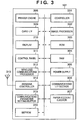
- FIG. 2 is a schematic block diagram showing an exemplary configuration of device A (digital camera 100).
- reference numeral 201 denotes a controller which controls the digital camera 100
- 202 denotes an image processor
- 203 denotes a ROM which stores control instructions (programs) and control data
- the RAM 204 prestores setup communications parameters used to form a network for communications parameter setting.
- Reference numeral 205 denotes a wireless communications processor which controls communications for a wireless LAN.
- Reference numeral 206 denotes an antenna and 207 denotes an antenna controller.
- Reference numeral 208 denotes an image pickup section which captures a pixel signal from a CCD 209.
- Reference numeral 210 denotes a card interface which controls a recording media card used to store picked-up images and setting information and 211 denotes a display.
- Reference numeral 212 denotes a control panel which contains buttons used to give photo-taking, playback, setting, and other commands.
- Reference numeral 213 denotes a power supply including a secondary cell.
- Reference numeral 214 denotes a communications interface section used for communications other than wireless communications. It is, for example, a USB, IEEE 1394, or other wired interface.
- Reference numeral 215 denotes a communications parameter setting start button used to start communications parameter setting.
- Reference numeral 216 denotes an EEPROM used to store communications parameters. It should be noted that the communications parameters are stored in the EEPROM, however, may be stored in other memories such as a Flash ROM.
- FIG 3 is a schematic block diagram showing an exemplary configuration of device B (printer 101).
- reference numeral 301 denotes a controller which controls the printer 101
- 302 denotes an image processor
- 303 denotes a ROM which stores control instructions (programs) and control data
- 304 denotes a RAM
- 305 denotes a power supply.
- the RAM 304 prestores setup communications parameters used to form a network for communications parameter setting.
- Reference numeral 306 denotes a communications interface section used for communications other than wireless communications. It is, for example, a USB, IEEE 1394, or other wired interface.
- Reference numeral 307 denotes a paper feeder/ejector which feeds/ejects printer paper.
- Reference numeral 308 denotes a printer engine which controls electrophotographic or inkjet printing.
- Reference numeral 309 denotes a card interface which controls a recording media card used to store images and 310 denotes a display.
- Reference numeral 311. denotes a control panel which contains menu, setting, and other buttons.
- Reference numeral 312 denotes a wireless communications processor which controls communications for a wireless LAN.
- Reference numeral 313 denotes an antenna and 314 denotes an antenna controller.
- Reference numeral 315 denotes a communications parameter setting start button used to start communications parameter setting.
- Reference numeral 316 denotes an EEPROM used to store communications parameters. It should be noted that the communications parameters are stored in the EEPROM, however, may be stored in other memories such as a Flash ROM.
- Available operation modes include an AUTO mode in which communications parameter setting information is set automatically between two devices and a PARTY mode in which communications parameter setting information is set automatically among three or more devices.
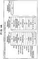
- FIGS 4A and 4B are diagrams showing an exemplary organization of operation modes and communications parameter setting information areas according to the first embodiment.
- the communications parameters are stored in the EEPROM 216 of the digital cameras 100 and 102 and in the EEPROM 316 of the printer 101.
- the communications parameters are stored as permanent communications parameters in AUTO-mode communications parameter setting information areas.
- permanent communications parameters 1 and 2 are already stored in AUTO-mode communications parameter setting information areas 401 and 402.
- the communications parameters are stored as temporary communications parameters in PARTY-mode communications parameter setting information areas.
- temporary communications parameters are already stored in a PARTY-mode communications parameter setting information area 404.
- the communications parameters stored in the AUTO-mode communications parameter setting information areas can be erased by user action. Otherwise, they are not erased.
- the information held in the areas described above include, SSID, Mode, Authentication, Cryptograph, Encryption key, Index, Channel, Device type, IP address setting, Management terminal MAC address, and Pointer.
- SSID is a network identifier needed for wireless LAN connection.
- Mode is information which indicates either an infrastructure mode or ad hoc mode.
- Authentication is information which represents an authentication type.
- Cryptograph is information which represents the type of encryption key.
- Index is an index of the key.
- Channel is information which represents a communications frequency.
- Device type is information which represents the type of remote device.
- IP address setting is information which represents the class of IP address.
- Management terminal MAC address is the MAC address of a remote terminal.
- Pointer is a link to the next area. The last field of the link contains a null code 403.
- FIG. 5 is a flowchart showing the process of receiving communications parameter setting information in AUTO operation mode.
- the user first sets the operation mode of the digital camera 100 to AUTO (S501) by pressing its communications parameter setting start button 103. At the same time, exchange of communications parameter settings is started (S502).
- the digital camera 100 waits for communications parameter setting information to be received from the digital camera 102 (S503).
- the digital camera 100 checks whether an AUTO-mode communications parameter setting information area is available to store the communications parameter setting information (S504).
- the received communications parameter setting information is stored in it as permanent communications parameters 3 (S505).
- the digital camera 100 displays a message on the display 211 stating that the exchange of communications parameter setting information has been successful (S506), and finishes processing.
- the digital camera 100 displays a message on the display 211 stating that the exchange of communications parameter settings has failed because no empty area is available (S507), and finishes processing.
- the communications parameter setting information may be stored in a temporary area.
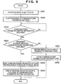
- FIG. 6 is a flowchart showing the process of storing information in a temporary area when there is no empty AUTO-mode communications parameter setting information area. Steps S601 to 606 in Figure 6 are the same as Steps S501 to 506 in Figure 5 , and thus only processes in Step S607 and later will be described here.
- Step S604 If it is found in Step S604 that there is no empty AUTO-mode communications parameter setting information area, the digital camera 100 informs the remote device that communications parameters will be stored in a temporary area (S607), stores the communications parameters in the temporary area (S608), and finishes processing.
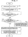
- FIG. 7 is a flowchart showing the process of exchanging communications parameter settings in PARTY operation mode.
- the user first sets the operation mode of the digital camera 100 to PARTY mode (S701) by pressing its communications parameter setting start button 103.
- exchange of communications parameter settings is started (S702).
- the digital camera 100 then waits for communications parameter setting information to be received from the printer 101 (S703).
- communications parameter setting information is received, since the digital camera 100 is operating in PARTY mode, the digital camera 100 checks whether a PARTY-mode communications parameter setting information area is available for use to store the communications parameters (S704).
- the received communications parameter setting information is stored in the area 404 as temporary communications parameters (S705).
- the digital camera 100 displays a message on the display 211 stating that the exchange of communications parameter setting information has been successful (S706), and finishes processing.
- the digital camera 100 displays a message on the display 211 stating that the exchange of communications parameter settings has failed because no empty area is available (S707) to save the information, and finishes processing.
- Figure 8 is a flowchart showing the process of achieving temporality in synchronization with power control. First, it is checked whether the digital camera 100 is powered off (S800). If the digital camera 100 is powered off, it is checked whether communications parameter setting information is stored in the area 404 (S801). If it is stored, the information stored in the area 404 is cleared completely (S802).
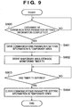
- Figure 9 is a flowchart showing the process of achieving temporality when a timer expires (at a preset time).
- the digital camera 100 checks whether exchange of communications parameter setting information in PARTY mode has been completed (S900). After completion of the exchange, the communications parameter setting information is saved in the area 404 (S901). At the same time, a temporary area storage monitoring timer T1 is started (S902). The digital camera 100 waits for the timer T1 to expire (S903). When the timer T1 expires, the communications parameter setting information stored in the area 404 is cleared (S904).
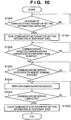
- FIG 10 is a flowchart showing the process of achieving temporality as triggering service execution completion between devices connected wirelessly using communications parameter setting information.
- the digital camera 100 checks whether exchange of communications parameter setting information in PARTY mode has been completed (S1000). After completion of the exchange, the communications parameter setting information is saved in the area 404 (S1001). Next, communications are started based on the communications parameters stored in the area 404 (S1002). Subsequently, the digital camera 100 starts a communications service in relation to the partner with which it has exchanged communications parameters (S1003) and performs the communications service (S1004). The digital camera 100 waits for the communications service to be completed (S1005). When the service is completed, the communications parameters stored in the area 404 is cleared (S1006).
- This service includes various processing, which is executed via communication based on communication parameters stored in the area 404, such as processing that the printer 101 prints an image received from the digital camera 100, and exchange processing of image between the digital cameras 100 and 102.
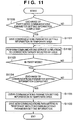
- FIG 11 is a flowchart showing the process of achieving temporality by exchanging and holding communications parameter setting information again in PARTY mode.
- the digital camera 100 checks whether exchange of communications parameter setting information in PARTY mode has been completed (S1100). After completion of the exchange, the communications parameter setting information is saved in the area 404 (S1101).
- the digital camera 100 starts communications based on the communications parameters stored in the area 404 and performs a communications service in relation to the partner with which it has exchanged communications parameters (S1102). After the service is finished, if exchange of communications parameter setting information in PARTY mode is specified as the operation mode (S1103), the digital camera 100 exchanges communications parameter setting information again.
- the area 404 is cleared (S1105).
- the accepted new communications parameter setting information is stored in the area 404 (S1106).
- the digital camera 100 can conduct communications any number of times easily with the communications partner with which it has exchanged parameters once in PARTY mode until it enters PARTY mode the next time.
- Figure 12 is a flowchart showing the process of achieving temporality by changing the operation mode.
- the communications parameter setting start button 104 is pressed when the printer 101 is conducting communications using the communications parameter setting information stored in a permanent communications parameter area (S1200).
- PARTY operation mode is set (S1201)
- the printer 101 temporarily saves the permanent communications parameters used for regular communications (S1202).
- the printer 101 starts exchange of communications parameter setting information in PARTY mode (S1203) and waits for the exchange to be completed (S1204).
- the printer 101 saves the PARTY-mode communications parameter setting information in a temporary area (S1205) and starts communications using the communications parameters (S1206). Then, the printer 101 performs a communications service in relation to the partner with which it has exchanged communications parameters (S1207). After the service is finished (S1208), the printer 101 restores the permanent communications parameters saved temporarily (S1209). The printer 101 clears the communications parameter setting information stored in the temporary area (S1210) and resumes operation using the communications parameters in the permanent area (S1211).
- Figure 13 is a diagram showing security levels available for each device.
- the tightness of security decreases in the order: security 1 > security 2 > security 3 > security 4 > security 5.
- the security levels available for device A are securities 1, 2, 3, and 5.
- the security levels available for device B are securities 1, 3, and 5.
- the security levels available for device C are securities 1, 2, 4, and 5.
- the highest of the security levels common to all the devices is security 1, and the lowest security level is security 5.
- FIG 14 is a flowchart showing the process of determining a security level depending on whether the operation mode is AUTO or PARTY.
- the digital camera 100 starts exchange of communications parameter setting information (S1401). It exchanges security levels with other devices (S1402), and checks whether it has collected security levels from all the devices currently located on the same network (S1403). If the digital camera 100 is in PARTY operation mode (S1404: YES), it compares the collected security levels (S1405). The digital camera 100 selects the lowest security level common to all the devices and sets it on the communications parameter setting information (S1406). In this case, security 5 in Figure 13 is selected. Then, the digital camera 100 exchanges the communications parameter setting information with all the other devices (S1409).
- the digital camera 100 compares the security levels (S1407), selects the highest security common to all the devices, and sets it on the communications parameter setting information (S1408). Then, the digital camera 100 exchanges the communications parameter setting information with the other devices (S1409).
- a high security level is selected while in PARTY mode, in which an unspecified number of people participate and parameters are temporary, a security level common to all people is selected to allow them to conduct communications. This makes it possible to balance interconnectability with security according to usage forms.
- the communications parameter setting information includes billing information.
- billing information is taken as an example, the description also applies to other highly confidential information.
- FIG. 15 is a flowchart showing the process of determining a security level depending on the presence or absence of billing information.
- the digital camera 100 starts exchange of communications parameter setting information (S1501). It exchanges security levels with other devices (S1502), and checks whether it has collected security levels from all the devices currently located on the same network (S1503).
- the digital camera 100 checks whether billing information is included in the communications parameter setting information (S1504). If billing information is included (S1504: YES), the digital camera 100 compares the collected security levels (S1505). The digital camera 100 selects the highest security level that will allow all users to conduct communications and sets it on the communications parameter setting information (S1506). Then, the digital camera 100 exchanges communications parameter setting information at a higher security level (S1509).
- the digital camera 100 sets the security level according to the operation mode (S1507) as in the case of the process in Figure 14 and sets the security corresponding to the operation mode on the communications parameter setting information (S1508). Then, the digital camera 100 exchanges the communications parameter setting information with the other devices (S1509).
- a high security level is required in AUTO operation mode, and it is possible to further increase security by rejecting communications with devices which do not satisfy a certain level of security.
- the present invention may be applied either to a system consisting of two or more devices (e.g., a host computer, interface devices, readers, printers, and the like) or to an apparatus (e.g., a copying machine, facsimile machine, or the like) consisting of a single device.
- a system consisting of two or more devices (e.g., a host computer, interface devices, readers, printers, and the like) or to an apparatus (e.g., a copying machine, facsimile machine, or the like) consisting of a single device.
- the object of the present invention can also be achieved by a recording medium containing software program code that implements the functions of the above embodiments: it is supplied to a system or apparatus, whose computer (or CPU or MPU) then reads the program code out of the storage medium and executes it.
- the program code itself read out of the recording medium will implement the functions of the above embodiments, and the recording medium which stores the program code will constitute the present invention.
- Available recording media for use to supply the program code include, for example, a flexible disk, hard disk, optical disk, magneto-optical disk, CD-ROM, CD-R, magnetic tape, non-volatile memory card, ROM, or the like.
- the functions of the above embodiments may be implemented not only by the program code read out and executed by the computer, but also by part or all of the actual processing executed, in accordance with instructions from the program code, by an OS (operating system) running on the computer.
- OS operating system
- the functions of the above embodiments may also be implemented by part or all of the actual processing executed by a CPU or the like contained in a function expansion card inserted into the computer or a function expansion unit connected to the computer if the processing is performed in accordance with instructions from the program code that has been read out of the storage medium and written into memory on the function expansion card or unit.
Description
- The present invention relates to a technique for setting communications parameter information.
- Methods are proposed which automatically set wireless communications parameters such as the network identifier (SSID), encryption methods, encryption key, authentication methods, and authentication key, which are said to be troublesome for users to set. Regarding automatic wireless LAN settings, for example, a method for transferring wireless parameter settings for an access point (relay station) and station (terminal) safely and automatically from the access point to the station by simple operations has actually been implemented as a product.
- Also, in carrying out wireless communication, products which assume various forms of usage have been implemented, including direct wireless communications (ad hoc communications) with specific or unspecified partners without an intervening access point.
- Detailed methods for secure data communications have been proposed because wireless parameter settings include network security information. For example, whether or not data transmission is permitted is determined based on the attribute values attached to the data, as well as on access policies. Also when receiving data, whether or not the data can be stored is determined based on the attribute values and policies. If it is possible, the received data is stored. In this way,
Patent Document 1 describes a secure data storage operation. - Also, proposals have been made in order to address the need to control the information to be distributed, either on a per-user basis or according to the place of use.
Patent Document 2 describes a system in which a management apparatus which has setting information (profiles) compatible with a plurality of networks provides information to each terminal according to the user of the terminal or the place of use, so that the user can make a desired connection using the setting information without being conscious of the network. - Incidentally,
Patent Documents - Patent Document 1: U.S. Publication No.
US-2003-028810 (Japanese Patent Laid-Open No.2003-051857 - Patent Document 2: Japanese Patent Laid-Open No.
- The above technique makes it possible to store safe data and to switch communications parameter setting information from one user to another on the network managed by the management apparatus described above. However, with future increases in the need for communications on unmanaged networks such as ad hoc networks, forms of communications will become complicated, and it will become necessary to exchange communications parameter setting information in multiple operation modes between specified wireless communications apparatus or between unspecified wireless communications apparatus. In that case, although from the viewpoint of security the user wants to control the way he/she stores the communications parameter setting information, such as permanently or temporarily, according to the operation mode, currently the switching of the communications parameter setting information is left to the user's manual control, which has involved complicated operation. Also, there have been problems in terms of security and operation. For example, the user may forget to erase temporary communications parameter setting information and continue to use it.
-
EP 1 526 444 A2 -
EP 1 538 792 A2 teaches that an encryption key used in an infrastructure mode is communicated between devices via communication using an encryption key that is generated based on a production number of a device input by a user and is used in an ad hoc mode.WO 2004/095778 A1 teaches that setup parameters to be used are set in advance or are determined to establish a communication channel. -
US 2005/201393 A1 teaches that a wireless LAN system in which data communication between a wireless station whose connection method as a method for wireless connection can be set to one of a plurality of connection methods. - The present invention realizes to make it
possible to set the security of communications parameter setting information depending on whether communications are conducted by a specific communications apparatus or an unspecified number of communications apparatuses, without complicated operations. - According to one aspect of the present invention, there is provided a communication apparatus as defined in
claim 1. - According to another aspect of the present invention, there is provided a control method for a communication apparatus as defined in claim 15.
- The other claims relate to further developments.
- Further features of the present invention will become apparent from the following description of exemplary embodiments (with reference to the attached drawings).
-
-
Figure 1 is a diagram showing an exemplary configuration of a wireless communications system according to a first embodiment; -
Figure 2 is a schematic block diagram showing an exemplary configuration of device A (digital camera 100); -
Figure 3 is a schematic block diagram showing an exemplary configuration of device B (printer 101); -
Figures 4A and4B are diagrams showing an exemplary organization of operation modes and communications parameter setting information areas according to the first embodiment; -
Figure 5 is a flowchart showing the process of receiving communications parameter setting information in AUTO operation mode; -
Figure 6 is a flowchart showing the process of storing information in a temporary area when there is no empty AUTO-mode communications parameter setting information area; -
Figure 7 is a flowchart showing the process of exchanging communications parameter settings in PARTY operation mode; -
Figure 8 is a flowchart showing the process of achieving temporality in synchronization with power control; -
Figure 9 is a flowchart showing the process of achieving temporality when a timer expires (at a preset time); -
Figure 10 is a flowchart showing the process of achieving temporality when services have been performed by devices connected wirelessly using communications parameter setting information; -
Figure 11 is a flowchart showing the process of achieving temporality by exchanging and holding communications parameter setting information again in PARTY mode; -
Figure 12 is a flowchart showing the process of achieving temporality of communications parameter setting information by changing the operation mode; -
Figure 13 is a diagram showing security levels available for each device; -
Figure 14 is a flowchart showing the process of determining a security level depending on whether the operation mode is AUTO or PARTY; and -
Figure 15 is a flowchart showing the process of determining a security level depending on the presence or absence of billing information. - The best mode for carrying out the invention will be described in detail below with reference to the drawings.
-
Figure 1 is a diagram showing an exemplary configuration of a wireless communications system according to a first embodiment. As shown inFigure 1 , device A is adigital camera 100. It has wireless LAN capabilities aswireless communications capabilities 105, and it constructs a network in communications parameter setting mode when a communications parametersetting start button 103 is pressed. Device B is aprinter 101. It has wireless LAN capabilities aswireless communications capabilities 106, and it constructs a network in communications parameter setting mode when a communications parametersetting start button 104 is pressed. Device C is adigital camera 102. It has wireless LAN capabilities aswireless communications capabilities 108, and it constructs a network in communications parameter setting mode when a communications parametersetting start button 107 is pressed. - Operation modes in the communications parameter setting mode and a method for setting them will be described later.
- Next, configurations of wireless communications apparatus A and B will be described with reference to
Figures 2 and3 . Device C has the same configuration as device A, and thus description thereof will be omitted. -
Figure 2 is a schematic block diagram showing an exemplary configuration of device A (digital camera 100). InFigure 2 ,reference numeral 201 denotes a controller which controls thedigital camera RAM 204 prestores setup communications parameters used to form a network for communications parameter setting.Reference numeral 205 denotes a wireless communications processor which controls communications for a wireless LAN.Reference numeral 206 denotes an antenna and 207 denotes an antenna controller. -
Reference numeral 208 denotes an image pickup section which captures a pixel signal from aCCD 209.Reference numeral 210 denotes a card interface which controls a recording media card used to store picked-up images and setting information and 211 denotes a display.Reference numeral 212 denotes a control panel which contains buttons used to give photo-taking, playback, setting, and other commands.Reference numeral 213 denotes a power supply including a secondary cell.Reference numeral 214 denotes a communications interface section used for communications other than wireless communications. It is, for example, a USB, IEEE 1394, or other wired interface.Reference numeral 215 denotes a communications parameter setting start button used to start communications parameter setting.Reference numeral 216 denotes an EEPROM used to store communications parameters. It should be noted that the communications parameters are stored in the EEPROM, however, may be stored in other memories such as a Flash ROM. -
Figure 3 is a schematic block diagram showing an exemplary configuration of device B (printer 101). InFigure 3 ,reference numeral 301 denotes a controller which controls theprinter RAM 304 prestores setup communications parameters used to form a network for communications parameter setting.Reference numeral 306 denotes a communications interface section used for communications other than wireless communications. It is, for example, a USB, IEEE 1394, or other wired interface. -
Reference numeral 307 denotes a paper feeder/ejector which feeds/ejects printer paper.Reference numeral 308 denotes a printer engine which controls electrophotographic or inkjet printing.Reference numeral 309 denotes a card interface which controls a recording media card used to store images and 310 denotes a display.Reference numeral 311. denotes a control panel which contains menu, setting, and other buttons.Reference numeral 312 denotes a wireless communications processor which controls communications for a wireless LAN.Reference numeral 313 denotes an antenna and 314 denotes an antenna controller.Reference numeral 315 denotes a communications parameter setting start button used to start communications parameter setting.Reference numeral 316 denotes an EEPROM used to store communications parameters. It should be noted that the communications parameters are stored in the EEPROM, however, may be stored in other memories such as a Flash ROM. - Next, communications parameters which are set in communications parameter setting processes in operation modes of each device will be described with reference to
Figures 4A and4B . Available operation modes include an AUTO mode in which communications parameter setting information is set automatically between two devices and a PARTY mode in which communications parameter setting information is set automatically among three or more devices. -
Figures 4A and4B are diagrams showing an exemplary organization of operation modes and communications parameter setting information areas according to the first embodiment. Incidentally, the communications parameters are stored in theEEPROM 216 of thedigital cameras EEPROM 316 of theprinter 101. - As shown in
Figures 4A and4B , in AUTO operation mode, the communications parameters are stored as permanent communications parameters in AUTO-mode communications parameter setting information areas. In this example,permanent communications parameters information areas - In PARTY operation mode, the communications parameters are stored as temporary communications parameters in PARTY-mode communications parameter setting information areas. In this example temporary communications parameters are already stored in a PARTY-mode communications parameter setting
information area 404. The communications parameters stored in the AUTO-mode communications parameter setting information areas can be erased by user action. Otherwise, they are not erased. - Incidentally, the information held in the areas described above include, SSID, Mode, Authentication, Cryptograph, Encryption key, Index, Channel, Device type, IP address setting, Management terminal MAC address, and Pointer. SSID is a network identifier needed for wireless LAN connection. Mode is information which indicates either an infrastructure mode or ad hoc mode. Authentication is information which represents an authentication type. Cryptograph is information which represents the type of encryption key. Index is an index of the key. Channel is information which represents a communications frequency. Device type is information which represents the type of remote device. IP address setting is information which represents the class of IP address. Management terminal MAC address is the MAC address of a remote terminal. Pointer is a link to the next area. The last field of the link contains a
null code 403. - Now description will be given of a process in which the
digital camera 100 receives communications parameter setting information from thedigital camera 102 with the above configuration when the operation mode of thedigital cameras -
Figure 5 is a flowchart showing the process of receiving communications parameter setting information in AUTO operation mode. The user first sets the operation mode of thedigital camera 100 to AUTO (S501) by pressing its communications parameter settingstart button 103. At the same time, exchange of communications parameter settings is started (S502). Thedigital camera 100 waits for communications parameter setting information to be received from the digital camera 102 (S503). When communications parameter setting information is received, since thedigital camera 100 is operating in AUTO operation mode, thedigital camera 100 checks whether an AUTO-mode communications parameter setting information area is available to store the communications parameter setting information (S504). - If the AUTO-mode communications parameter setting
information area 403 inFigure 4A is empty, the received communications parameter setting information is stored in it as permanent communications parameters 3 (S505). Thedigital camera 100 displays a message on thedisplay 211 stating that the exchange of communications parameter setting information has been successful (S506), and finishes processing. - If there is no empty AUTO-mode communications parameter setting information area, the
digital camera 100 displays a message on thedisplay 211 stating that the exchange of communications parameter settings has failed because no empty area is available (S507), and finishes processing. When no area is available, the communications parameter setting information may be stored in a temporary area. -
Figure 6 is a flowchart showing the process of storing information in a temporary area when there is no empty AUTO-mode communications parameter setting information area. Steps S601 to 606 inFigure 6 are the same as Steps S501 to 506 inFigure 5 , and thus only processes in Step S607 and later will be described here. - If it is found in Step S604 that there is no empty AUTO-mode communications parameter setting information area, the
digital camera 100 informs the remote device that communications parameters will be stored in a temporary area (S607), stores the communications parameters in the temporary area (S608), and finishes processing. - In this way, by using a temporary area even in AUTO operation mode, it is possible to continue communications without causing an error even if no AUTO-mode communications parameter setting information area is available.
- Next, description will be given of a process in which communications parameter settings are exchanged among the
digital camera 100,printer 101, anddigital camera 102 in PARTY operation mode. Here, a process in which thedigital camera 100 receives communications parameter setting information from theprinter 101 will be described with reference toFigure 7 . -
Figure 7 is a flowchart showing the process of exchanging communications parameter settings in PARTY operation mode. The user first sets the operation mode of thedigital camera 100 to PARTY mode (S701) by pressing its communications parameter settingstart button 103. At the same time, exchange of communications parameter settings is started (S702). Thedigital camera 100 then waits for communications parameter setting information to be received from the printer 101 (S703). When communications parameter setting information is received, since thedigital camera 100 is operating in PARTY mode, thedigital camera 100 checks whether a PARTY-mode communications parameter setting information area is available for use to store the communications parameters (S704). - If the PARTY-mode communications parameter setting information area in
Figure 4B is empty, the received communications parameter setting information is stored in thearea 404 as temporary communications parameters (S705). Thedigital camera 100 then displays a message on thedisplay 211 stating that the exchange of communications parameter setting information has been successful (S706), and finishes processing. - On the other hand, if the PARTY-mode communications parameter setting information area is already in use, the
digital camera 100 displays a message on thedisplay 211 stating that the exchange of communications parameter settings has failed because no empty area is available (S707) to save the information, and finishes processing. - Next, description will be given of methods for achieving temporality of communications parameter setting information by automatically clearing the communications parameter setting information held in the
area 404 in PARTY mode. It should be noted that the communications parameter setting information stored in the PARTY-mode communications parameter setting information area is cleared (erasing), and information stored in the AUTO-mode communications parameter setting information areas is not cleared. - As a first method, description will be given of a method for clearing the communications parameter setting information held as temporary communications parameters of the
digital camera 100, in synchronization with power control. -
Figure 8 is a flowchart showing the process of achieving temporality in synchronization with power control. First, it is checked whether thedigital camera 100 is powered off (S800). If thedigital camera 100 is powered off, it is checked whether communications parameter setting information is stored in the area 404 (S801). If it is stored, the information stored in thearea 404 is cleared completely (S802). - In this way, temporality is achieved by turning off the power. Although only turn-off of power has been described here, the same effect can be obtained by clearing the
area 404 at power-on. - Next, as a second method, description will be given of a method for clearing the communications parameter setting information held as temporary communications parameters of the
digital camera 100 after a lapse of a certain period of time. -
Figure 9 is a flowchart showing the process of achieving temporality when a timer expires (at a preset time). First, thedigital camera 100 checks whether exchange of communications parameter setting information in PARTY mode has been completed (S900). After completion of the exchange, the communications parameter setting information is saved in the area 404 (S901). At the same time, a temporary area storage monitoring timer T1 is started (S902). Thedigital camera 100 waits for the timer T1 to expire (S903). When the timer T1 expires, the communications parameter setting information stored in thearea 404 is cleared (S904). - Next, as a third method, description will be given of a method for clearing the communications parameter setting information held as temporary communications parameters of the
digital camera 100 after completion of a communications service. -
Figure 10 is a flowchart showing the process of achieving temporality as triggering service execution completion between devices connected wirelessly using communications parameter setting information. First, thedigital camera 100 checks whether exchange of communications parameter setting information in PARTY mode has been completed (S1000). After completion of the exchange, the communications parameter setting information is saved in the area 404 (S1001). Next, communications are started based on the communications parameters stored in the area 404 (S1002). Subsequently, thedigital camera 100 starts a communications service in relation to the partner with which it has exchanged communications parameters (S1003) and performs the communications service (S1004). Thedigital camera 100 waits for the communications service to be completed (S1005). When the service is completed, the communications parameters stored in thearea 404 is cleared (S1006). This service includes various processing, which is executed via communication based on communication parameters stored in thearea 404, such as processing that theprinter 101 prints an image received from thedigital camera 100, and exchange processing of image between thedigital cameras - Thus, in the case of communications parameter setting information which combines a one-time service ticket, once service is performed, the communications parameter setting information is erased, making it impossible to conduct a next communications session. Consequently the service no longer can be started. This makes it possible to implement a one-time service.
- Next, as a fourth method, description will be given of a method for clearing the communications parameter setting information when new communications parameter setting information is stored, in a case where the communications parameter setting information has been held as temporary communications parameters of the
digital camera 100. -
Figure 11 is a flowchart showing the process of achieving temporality by exchanging and holding communications parameter setting information again in PARTY mode. First, thedigital camera 100 checks whether exchange of communications parameter setting information in PARTY mode has been completed (S1100). After completion of the exchange, the communications parameter setting information is saved in the area 404 (S1101). Next, thedigital camera 100 starts communications based on the communications parameters stored in thearea 404 and performs a communications service in relation to the partner with which it has exchanged communications parameters (S1102). After the service is finished, if exchange of communications parameter setting information in PARTY mode is specified as the operation mode (S1103), thedigital camera 100 exchanges communications parameter setting information again. When the exchange is completed (S1104), thearea 404 is cleared (S1105). The accepted new communications parameter setting information is stored in the area 404 (S1106). - Consequently, the
digital camera 100 can conduct communications any number of times easily with the communications partner with which it has exchanged parameters once in PARTY mode until it enters PARTY mode the next time. - Next, description will be given of a case in which the
printer 101 exchanges communications parameter setting information in AUTO mode, and then exchanges communications parameter setting information in PARTY mode during communications. -
Figure 12 is a flowchart showing the process of achieving temporality by changing the operation mode. First, the communications parameter settingstart button 104 is pressed when theprinter 101 is conducting communications using the communications parameter setting information stored in a permanent communications parameter area (S1200). When PARTY operation mode is set (S1201), theprinter 101 temporarily saves the permanent communications parameters used for regular communications (S1202). At the same time, theprinter 101 starts exchange of communications parameter setting information in PARTY mode (S1203) and waits for the exchange to be completed (S1204). - Subsequently, when the exchange is completed, the
printer 101 saves the PARTY-mode communications parameter setting information in a temporary area (S1205) and starts communications using the communications parameters (S1206). Then, theprinter 101 performs a communications service in relation to the partner with which it has exchanged communications parameters (S1207). After the service is finished (S1208), theprinter 101 restores the permanent communications parameters saved temporarily (S1209). Theprinter 101 clears the communications parameter setting information stored in the temporary area (S1210) and resumes operation using the communications parameters in the permanent area (S1211). - Thus, when a user regularly uses a printer included in a network constructed in a fixed fashion at home, even if the printer is used temporarily by another user, the original user can subsequently restore the settings of the fixed network automatically. On the other hand, the user who wants to use the printer temporarily can perform services by exchanging communications parameter setting information in PARTY mode.
- Next, a second embodiment of the present invention will be described in detail below with reference to the drawings. In the second embodiment, description will be given of a case in which security levels contained in communications parameter setting information is controlled in operation mode.
-
Figure 13 is a diagram showing security levels available for each device. InFigure 13 , the tightness of security decreases in the order:security 1 >security 2 >security 3 >security 4 >security 5. In the example ofFigure 13 , the security levels available for device A aresecurities securities securities security 1, and the lowest security level issecurity 5. - Now, detailed description will be given of how to ensure security and increase safety while maintaining interconnectability among multiple devices by changing the tightness of security depending on the operation mode.
- First, description will be given of a case in which communications parameter setting information is exchanged by selecting a security level according to the operation mode and setting the selected security level on the communications parameter setting information.
-
Figure 14 is a flowchart showing the process of determining a security level depending on whether the operation mode is AUTO or PARTY. First, thedigital camera 100 starts exchange of communications parameter setting information (S1401). It exchanges security levels with other devices (S1402), and checks whether it has collected security levels from all the devices currently located on the same network (S1403). If thedigital camera 100 is in PARTY operation mode (S1404: YES), it compares the collected security levels (S1405). Thedigital camera 100 selects the lowest security level common to all the devices and sets it on the communications parameter setting information (S1406). In this case,security 5 inFigure 13 is selected. Then, thedigital camera 100 exchanges the communications parameter setting information with all the other devices (S1409). - On the other hand, if the
digital camera 100 is in AUTO operation mode, it compares the security levels (S1407), selects the highest security common to all the devices, and sets it on the communications parameter setting information (S1408). Then, thedigital camera 100 exchanges the communications parameter setting information with the other devices (S1409). - That is, in AUTO mode, in which information has permanence, a high security level is selected while in PARTY mode, in which an unspecified number of people participate and parameters are temporary, a security level common to all people is selected to allow them to conduct communications. This makes it possible to balance interconnectability with security according to usage forms.
- Next, description will be given of the process of determining a security level when it is desired to raise the security level even in PARTY operation mode because the communications parameter setting information includes billing information. Incidentally, although billing information is taken as an example, the description also applies to other highly confidential information.
-
Figure 15 is a flowchart showing the process of determining a security level depending on the presence or absence of billing information. First, thedigital camera 100 starts exchange of communications parameter setting information (S1501). It exchanges security levels with other devices (S1502), and checks whether it has collected security levels from all the devices currently located on the same network (S1503). Next, thedigital camera 100 checks whether billing information is included in the communications parameter setting information (S1504). If billing information is included (S1504: YES), thedigital camera 100 compares the collected security levels (S1505). Thedigital camera 100 selects the highest security level that will allow all users to conduct communications and sets it on the communications parameter setting information (S1506). Then, thedigital camera 100 exchanges communications parameter setting information at a higher security level (S1509). - On the other hand, if no billing information is included, the
digital camera 100 sets the security level according to the operation mode (S1507) as in the case of the process inFigure 14 and sets the security corresponding to the operation mode on the communications parameter setting information (S1508). Then, thedigital camera 100 exchanges the communications parameter setting information with the other devices (S1509). - This makes it possible to raise the security level even in PARTY mode when communicating highly confidential information.
- A high security level is required in AUTO operation mode, and it is possible to further increase security by rejecting communications with devices which do not satisfy a certain level of security.
- As another embodiment, by allowing the user to select from a plurality of methods for temporarily holding parameters in PARTY mode, it is possible to achieving temporality according to circumstances.
- Although digital cameras and a printer have been cited as devices, the present invention is not limited to them and may be applied to notebook personal computers having wireless communication capability, mobile terminals, and the like.
- Incidentally, the present invention may be applied either to a system consisting of two or more devices (e.g., a host computer, interface devices, readers, printers, and the like) or to an apparatus (e.g., a copying machine, facsimile machine, or the like) consisting of a single device.
- Needless to say, the object of the present invention can also be achieved by a recording medium containing software program code that implements the functions of the above embodiments: it is supplied to a system or apparatus, whose computer (or CPU or MPU) then reads the program code out of the storage medium and executes it.
- In that case, the program code itself read out of the recording medium will implement the functions of the above embodiments, and the recording medium which stores the program code will constitute the present invention.
- Available recording media for use to supply the program code include, for example, a flexible disk, hard disk, optical disk, magneto-optical disk, CD-ROM, CD-R, magnetic tape, non-volatile memory card, ROM, or the like.
- Needless to say, the functions of the above embodiments may be implemented not only by the program code read out and executed by the computer, but also by part or all of the actual processing executed, in accordance with instructions from the program code, by an OS (operating system) running on the computer.
- Furthermore, needless to say, the functions of the above embodiments may also be implemented by part or all of the actual processing executed by a CPU or the like contained in a function expansion card inserted into the computer or a function expansion unit connected to the computer if the processing is performed in accordance with instructions from the program code that has been read out of the storage medium and written into memory on the function expansion card or unit.
- While the present invention has been described with reference to exemplary embodiments, it is to be understood that the invention is not limited to the disclosed exemplary embodiments. The scope of the following claims is to be accorded the broadest interpretation so as to encompass all such modifications and equivalent structures and functions.
- This application claims the benefit of Japanese Patent Application No.
2006-077401, filed March 20, 2006 -
Case 1. A communications apparatus which sets communications parameter information, comprising:- selection means for selecting one of a first operation mode in which communications parameter information is set in relation to a specific communications apparatus and a second operation mode in which communications parameter information is set in relation to an unspecified number of communications apparatus; and
- control means for controlling security of said communications parameter information which is set in relation to said specific communications apparatus or said unspecified number of communications apparatus, according to an operation mode selected by said selection means.
-
Case 2. The communications apparatus according toCase 1, wherein said control means changes storage areas to store said communications parameter information, according to said selected operation mode. -
Case 3. The communications apparatus according toCase 1, wherein said control means manages said communications parameter information as either permanent stored information or temporary stored information, according to said selected operation mode. -
Case 4. The communications apparatus according toCase 3, said control means erases communications parameter information managed as the temporary stored information when said communications apparatus is powered on or off. -
Case 5. The communications apparatus according toCase 3, said control means erases communications parameter information managed as the temporary stored information when a predetermined period lapses. - Case 6. The communications apparatus according to
Case 3, said control means erases communications parameter information managed as the temporary stored information when a service is performed on a network corresponding to said communications parameter information. - Case 7. The communications apparatus according to
Case 3, said control means continues to store communications parameter information managed as the temporary stored information until communications parameter information is newly set in the second operation mode. - Case 8. The communications apparatus according to
Case 3, said control means manages communications parameter information set by said first operation mode as the permanent stored information, and manages communications parameter information set by said second operation mode as the temporary stored information. - Case 9. The communications apparatus according to
Case 3, wherein when setting second communications parameter information in said second operation mode after forming a network by first communications parameter information in said first operation mode, a network is formed by said second communications parameter information with said first communications parameter information saved temporarily, and then a wireless network is formed by said first communications parameter information again. - Case 10. The communications apparatus according to
Case 1, further comprising:- exchange means for exchanging security level information when setting said communications parameter information, wherein
- said control means controls security of said communications parameter information according to said exchanged security level information and said selected operation mode.
- Case 11. The communications apparatus according to Case 10, wherein regarding said security, the highest common security level is set in said first operation mode and the lowest common security level is set in said second operation mode.
- Case 12. The communications apparatus according to Case 10, wherein the security of said communications parameter information in said first operation mode is controlled by setting the highest common security level when specific additional information is included in said communications parameter information and setting the lowest common security level when no additional information is included in said communications parameter information.
- Case 13. A control method for a communications apparatus which sets communications parameter information comprising:
- a selection step of selecting one of a first operation mode in which communications parameter information is set in relation to a specific communications apparatus and a second operation mode in which communications parameter information is set in relation to an unspecified number of communications apparatus; and
- a control step of controlling security of said communications parameter information which is set in relation to said specific communications apparatus or said unspecified number of communications apparatus, according to an operation mode selected by said selection step.
- Case 14. A program which is recorded on a computer-readable recording medium and makes a computer perform the control method for the communications apparatus according to Case 13.
- Case 15. A computer-readable recording medium containing a program which makes a computer perform the control method for the communications apparatus according to Case 13.
Claims (15)
- A communication apparatus comprising:selection means for selecting one of a first operation mode for persistently using communication parameter setting information for wireless communication to be set and a second operation mode for temporarily using the communication parameter setting information to be set;processing means for performing, in the selected operation mode, a setting process of setting, among plural apparatuses (100-102), the communication parameter setting information; andcontrol means for controlling the communication apparatus to operate communication using the communication parameter setting information set by the processing means; whereinin the first operation mode, the communication parameter setting information set by the processing means is stored (S505) for resuming operation therewith (S1211) after completing a communication service (S1208) using the communication parameter setting information, andin the second operation mode, after completing a communication service (S1005) for communicating images using the communication parameter setting information set by the processing means, conducting a next communication service using the communication parameter setting information is made impossible (S1006).
- The communication apparatus according to claim 1, configured such thatin the first operation mode, the communication parameter setting information is stored (S505) in a permanent storage area, andin the second operation mode, the communication parameter setting information is stored (S705) in a temporary storage area.
- The communication apparatus according to claim 1, configured such that the control means erases (S802) the communication parameter setting information stored in the second operation mode when the communication apparatus is powered on or off.
- The communication apparatus according to claim 1, configured such that the control means erases (S904) the communication parameter setting information stored in the second operation mode when a predetermined period lapses.
- The communication apparatus according to claim 1, configured such that the control means continues to store the communication parameter setting information stored in the second operation mode until the communication parameter setting information is newly set (S1106) in the second operation mode.
- The communication apparatus according to claim 1, configured such that, when setting a second communication parameter setting information in the second operation mode after forming a network by a first communication parameter setting information in the first operation mode (S1200), a network is formed by the second communication parameter setting information with the first communication parameter setting information saved temporarily (S1202), and then a wireless network is formed by the first communication parameter setting information again (S1211).
- The communication apparatus according to any one of claims 1 to 6, configured such that, when a communication parameter setting start button (103) is pressed, a network is constructed and one of the first and the second operation mode is selected.
- The communication apparatus according to any one of claims 1 to 7, configured such that,in the first operation mode, the communication parameter setting information is set in relation to a specific communication apparatus, andin the second operation mode, the communication parameter setting information is set in relation to an unspecified number of communication apparatuses.
- The communication apparatus according to any one of claims 1 to 8, further comprising:exchange means for exchanging security levels (S1402) when setting the communication parameter setting information, whereinsaid control means is configured to control security of the communication parameter setting information according to the exchanged security level information by setting the highest common security level (S1408) in the first operation mode and the lowest common security level (S1406) in the second operation mode.
- The communication apparatus according to claim 9, wherein the security of the communication parameter setting information in the second operation mode is controlled by setting the highest common security level (S1506) when specific additional information is included in the communication parameter setting information and setting the lowest common security level when no additional information is included in the communication parameter setting information.
- The communication apparatus according to any one of claims 1 to 10, wherein the communication parameter setting information comprises at least one of network identifier, encryption method, encryption key, authentication method, or authentication key.
- The communication apparatus according to any one of claims 1 to 11, wherein the setting of the communication parameter setting information is performed over a wireless LAN.
- The communication apparatus according to any one of claims 1 to 12, wherein the communication parameter setting information stored in the first operation mode is erased in response to a user instruction.
- The communication apparatus according to any one of claims 1 to 13, wherein the communication parameter setting information stored in the second operation mode is erased after completing a communication service (S1005) for communicating images.
- A control method for a communication apparatus, comprising:a selection step of selecting one of a first operation mode for persistently using communication parameter setting information for wireless communication to be set and a second operation mode for temporarily using the communication parameter setting information to be set;a setting step of setting, in the selected operation mode and among plural apparatuses (100-102), the communication parameter setting information; anda controlling step of controlling the communication apparatus to operate communication using the communication parameter setting information set at the setting step; whereinin the first operation mode, the communication parameter setting information set at the setting step is stored (S505) for resuming operation therewith (S1211) after completing a communication service (S1208) using the communication parameter setting information, andin the second operation mode, after completing a communication service (S1005) for communicating images using the communication parameter setting information set at the setting step, conducting a next communication service using the communication parameter setting information is made impossible (S1006).
Applications Claiming Priority (2)
| Application Number | Priority Date | Filing Date | Title |
|---|---|---|---|
| JP2006077401A JP4781139B2 (en) | 2006-03-20 | 2006-03-20 | COMMUNICATION DEVICE AND ITS CONTROL METHOD |
| EP07739556.4A EP1997278B1 (en) | 2006-03-20 | 2007-03-16 | Communications apparatus and control method therefor |
Related Parent Applications (2)
| Application Number | Title | Priority Date | Filing Date |
|---|---|---|---|
| EP07739556.4A Division-Into EP1997278B1 (en) | 2006-03-20 | 2007-03-16 | Communications apparatus and control method therefor |
| EP07739556.4A Division EP1997278B1 (en) | 2006-03-20 | 2007-03-16 | Communications apparatus and control method therefor |
Publications (2)
| Publication Number | Publication Date |
|---|---|
| EP2947842A1 EP2947842A1 (en) | 2015-11-25 |
| EP2947842B1 true EP2947842B1 (en) | 2018-05-16 |
Family
ID=38522569
Family Applications (2)
| Application Number | Title | Priority Date | Filing Date |
|---|---|---|---|
| EP15000105.5A Active EP2947842B1 (en) | 2006-03-20 | 2007-03-16 | Communications device and control method therefor |
| EP07739556.4A Expired - Fee Related EP1997278B1 (en) | 2006-03-20 | 2007-03-16 | Communications apparatus and control method therefor |
Family Applications After (1)
| Application Number | Title | Priority Date | Filing Date |
|---|---|---|---|
| EP07739556.4A Expired - Fee Related EP1997278B1 (en) | 2006-03-20 | 2007-03-16 | Communications apparatus and control method therefor |
Country Status (8)
| Country | Link |
|---|---|
| US (2) | US8695057B2 (en) |
| EP (2) | EP2947842B1 (en) |
| JP (1) | JP4781139B2 (en) |
| KR (1) | KR100968786B1 (en) |
| CN (4) | CN102263815B (en) |
| ES (1) | ES2671019T3 (en) |
| RU (1) | RU2405268C2 (en) |
| WO (1) | WO2007108545A1 (en) |
Families Citing this family (21)
| Publication number | Priority date | Publication date | Assignee | Title |
|---|---|---|---|---|
| US8862866B2 (en) | 2003-07-07 | 2014-10-14 | Certicom Corp. | Method and apparatus for providing an adaptable security level in an electronic communication |
| JP4781139B2 (en) * | 2006-03-20 | 2011-09-28 | キヤノン株式会社 | COMMUNICATION DEVICE AND ITS CONTROL METHOD |
| JP4886463B2 (en) | 2006-10-20 | 2012-02-29 | キヤノン株式会社 | Communication parameter setting method, communication apparatus, and management apparatus for managing communication parameters |
| JP4891268B2 (en) * | 2008-01-15 | 2012-03-07 | キヤノン株式会社 | Communication device, control method, program, storage medium |
| JP5538680B2 (en) | 2008-01-15 | 2014-07-02 | キヤノン株式会社 | Communication device, control method, program, storage medium |
| JP5538692B2 (en) * | 2008-08-08 | 2014-07-02 | キヤノン株式会社 | COMMUNICATION DEVICE, COMMUNICATION DEVICE CONTROL METHOD, COMPUTER PROGRAM |
| JP5448434B2 (en) * | 2008-12-11 | 2014-03-19 | キヤノン株式会社 | COMMUNICATION DEVICE, COMMUNICATION DEVICE CONTROL METHOD, COMPUTER PROGRAM |
| JP5409147B2 (en) * | 2009-07-03 | 2014-02-05 | キヤノン株式会社 | COMMUNICATION DEVICE, COMMUNICATION DEVICE CONTROL METHOD, PROGRAM |
| JP2012175160A (en) * | 2011-02-17 | 2012-09-10 | Sony Corp | Wireless communication device, wireless communication method, program, and wireless communication system |
| JP5901231B2 (en) * | 2011-11-04 | 2016-04-06 | オリンパス株式会社 | Wireless communication terminal |
| JP5868196B2 (en) | 2012-01-27 | 2016-02-24 | キヤノン株式会社 | COMMUNICATION DEVICE, ITS CONTROL METHOD, AND PROGRAM |
| JP6152947B2 (en) * | 2012-12-27 | 2017-06-28 | パナソニックIpマネジメント株式会社 | Electronic devices that can communicate with other devices |
| JP6128844B2 (en) * | 2012-12-28 | 2017-05-17 | キヤノン株式会社 | COMMUNICATION DEVICE, ITS CONTROL METHOD, PROGRAM, AND STORAGE MEDIUM |
| JP5597274B2 (en) * | 2013-03-25 | 2014-10-01 | キヤノン株式会社 | Communication device, control method, program, storage medium |
| JP6366386B2 (en) * | 2014-06-30 | 2018-08-01 | キヤノン株式会社 | COMMUNICATION DEVICE, IMAGING DEVICE, COMMUNICATION DEVICE CONTROL METHOD, AND PROGRAM |
| CN106576240B (en) * | 2014-07-25 | 2020-03-10 | 佳能株式会社 | Communication apparatus and control method of communication apparatus |
| RU2598337C2 (en) * | 2014-12-19 | 2016-09-20 | Закрытое акционерное общество "Лаборатория Касперского" | System and method of selecting means of interception of data transmitted over network |
| JP5914709B2 (en) * | 2015-01-16 | 2016-05-11 | キヤノン株式会社 | COMMUNICATION DEVICE, COMMUNICATION DEVICE CONTROL METHOD, PROGRAM |
| JP6289548B2 (en) * | 2016-06-29 | 2018-03-07 | キヤノン株式会社 | Device, control method thereof, and program |
| JP6852515B2 (en) * | 2017-03-31 | 2021-03-31 | 沖電気工業株式会社 | Sensor management system, sensor management method, sensor management program and sensor management device |
| JP6541815B2 (en) * | 2018-02-07 | 2019-07-10 | キヤノン株式会社 | Communication system, communication apparatus, control method therefor, and program |
Family Cites Families (38)
| Publication number | Priority date | Publication date | Assignee | Title |
|---|---|---|---|---|
| US5241402A (en) * | 1989-12-04 | 1993-08-31 | Xerox Corporation | Concurrent modem control in a reprographic machine |
| US5311596A (en) * | 1992-08-31 | 1994-05-10 | At&T Bell Laboratories | Continuous authentication using an in-band or out-of-band side channel |
| KR950013305B1 (en) * | 1992-11-10 | 1995-11-02 | 삼성전자주식회사 | The paging receiver |
| EP0676693B1 (en) * | 1994-04-05 | 2000-08-23 | International Business Machines Corporation | Method and system for dynamically selecting a communication mode |
| JPH09282561A (en) | 1996-04-18 | 1997-10-31 | Tec Corp | Radio type merchandise sales registering device |
| JPH118630A (en) | 1997-06-17 | 1999-01-12 | Sharp Corp | Communication terminal system |
| US6025695A (en) * | 1997-07-09 | 2000-02-15 | Friel; Daniel D. | Battery operating system |
| JPH1168786A (en) * | 1997-08-27 | 1999-03-09 | Yamatake Honeywell Co Ltd | Communication equipment and address setting method |
| US7173651B1 (en) * | 1998-06-02 | 2007-02-06 | Knowles Andrew T | Apparatus and system for prompt digital photo delivery and archival |
| SE522794C2 (en) | 2001-02-23 | 2004-03-09 | Ericsson Telefon Ab L M | Device and method for communicating electronic data via a network infrastructure having a unicast mechanism and multicast mechanism |
| US7120129B2 (en) * | 2001-03-13 | 2006-10-10 | Microsoft Corporation | System and method for achieving zero-configuration wireless computing and computing device incorporating same |
| JP4029629B2 (en) | 2001-03-27 | 2008-01-09 | セイコーエプソン株式会社 | COMMUNICATION DEVICE, COMMUNICATION METHOD, AND PROGRAM |
| FI113145B (en) * | 2001-05-03 | 2004-02-27 | Nokia Corp | Hide device |
| JP2003051857A (en) * | 2001-08-06 | 2003-02-21 | Nec Corp | Data communication system, data communication terminal and data communication method used by the terminal, and its program |
| JP2005057312A (en) * | 2001-08-06 | 2005-03-03 | Matsushita Electric Ind Co Ltd | Digital camera data transmission stand |
| JP3937820B2 (en) * | 2001-11-27 | 2007-06-27 | セイコーエプソン株式会社 | Wireless network adapter |
| US20030191845A1 (en) | 2002-04-03 | 2003-10-09 | Hinds John Sherman | Method, apparatus and system for establishing communications between communications devices |
| JP3748106B2 (en) * | 2002-04-25 | 2006-02-22 | ソニー株式会社 | COMMUNICATION SYSTEM, INFORMATION PROCESSING DEVICE AND METHOD, RECORDING MEDIUM, AND PROGRAM |
| JP2003348070A (en) * | 2002-05-29 | 2003-12-05 | Hitachi Ltd | Secured communication method and node device used for same |
| JP4672968B2 (en) | 2003-04-23 | 2011-04-20 | キヤノン株式会社 | Imaging device |
| JP4136771B2 (en) | 2003-04-23 | 2008-08-20 | キヤノン株式会社 | COMMUNICATION SYSTEM, COMMUNICATION DEVICE, ITS CONTROL METHOD, AND COMPUTER PROGRAM |
| JP4278434B2 (en) * | 2003-05-19 | 2009-06-17 | パナソニック株式会社 | Communication apparatus, information sharing system, and information sharing method |
| US8555344B1 (en) * | 2003-06-05 | 2013-10-08 | Mcafee, Inc. | Methods and systems for fallback modes of operation within wireless computer networks |
| JP2005020112A (en) * | 2003-06-24 | 2005-01-20 | Hitachi Ltd | Network setting system, managing apparatus, terminal and network setting method |
| US8452847B2 (en) * | 2003-09-22 | 2013-05-28 | Broadcom Corporation | Processor sharing between in-range devices |
| US20050130647A1 (en) | 2003-10-22 | 2005-06-16 | Brother Kogyo Kabushiki Kaisha | Wireless lan system, communication terminal and communication program |
| JP2005151258A (en) | 2003-11-17 | 2005-06-09 | Toshiba Corp | Electronic apparatus and program |
| JP4574338B2 (en) | 2003-12-04 | 2010-11-04 | キヤノン株式会社 | Setting method for wireless communication, peripheral device for performing wireless communication, and information processing device |
| JP4660100B2 (en) * | 2004-02-26 | 2011-03-30 | 三洋電機株式会社 | Server device |
| US7596226B2 (en) * | 2004-07-19 | 2009-09-29 | Nokia Corporation | Mobile terminal, method and computer program product for storing and retrieving network parameters |
| ATE387050T1 (en) * | 2004-08-02 | 2008-03-15 | Alcatel Lucent | SHARED RESOURCES IN A MULTIMANAGER ENVIRONMENT |
| FI20050092A0 (en) | 2004-09-08 | 2005-01-28 | Nokia Corp | Group details for group services |
| US7941177B2 (en) * | 2004-09-15 | 2011-05-10 | Samsung Electronics Co., Ltd | Wireless terminal apparatus for automatically changing WLAN standard and method thereof |
| WO2006080623A1 (en) * | 2004-09-22 | 2006-08-03 | Samsung Electronics Co., Ltd. | Method and apparatus for managing communication security in wireless network |
| JP3979413B2 (en) * | 2004-09-30 | 2007-09-19 | ブラザー工業株式会社 | Setting management program and setting management system |
| KR100666947B1 (en) * | 2005-02-01 | 2007-01-10 | 삼성전자주식회사 | Network Access Method of WLAN Terminal And Network system thereof |
| US7929486B2 (en) * | 2005-11-22 | 2011-04-19 | Broadcom Corporation | Programmable wireless access point supporting configuration profile updating |
| JP4781139B2 (en) * | 2006-03-20 | 2011-09-28 | キヤノン株式会社 | COMMUNICATION DEVICE AND ITS CONTROL METHOD |
-
2006
- 2006-03-20 JP JP2006077401A patent/JP4781139B2/en active Active
-
2007
- 2007-03-16 CN CN201110178693.XA patent/CN102263815B/en not_active Expired - Fee Related
- 2007-03-16 RU RU2008141300/09A patent/RU2405268C2/en active
- 2007-03-16 CN CN2007800097698A patent/CN101405996B/en not_active Expired - Fee Related
- 2007-03-16 ES ES15000105.5T patent/ES2671019T3/en active Active
- 2007-03-16 US US12/162,899 patent/US8695057B2/en active Active
- 2007-03-16 CN CN201110178725.6A patent/CN102263816B/en active Active
- 2007-03-16 KR KR1020087020435A patent/KR100968786B1/en active IP Right Grant
- 2007-03-16 WO PCT/JP2007/056115 patent/WO2007108545A1/en active Application Filing
- 2007-03-16 EP EP15000105.5A patent/EP2947842B1/en active Active
- 2007-03-16 CN CN201110178679.XA patent/CN102264072B/en not_active Expired - Fee Related
- 2007-03-16 EP EP07739556.4A patent/EP1997278B1/en not_active Expired - Fee Related
-
2011
- 2011-07-07 US US13/177,796 patent/US8931040B2/en active Active
Non-Patent Citations (1)
| Title |
|---|
| None * |
Also Published As
| Publication number | Publication date |
|---|---|
| CN102263815B (en) | 2014-11-19 |
| EP1997278A1 (en) | 2008-12-03 |
| CN102263816B (en) | 2014-04-30 |
| EP1997278B1 (en) | 2018-05-23 |
| WO2007108545A1 (en) | 2007-09-27 |
| RU2008141300A (en) | 2010-04-27 |
| RU2405268C2 (en) | 2010-11-27 |
| CN102263816A (en) | 2011-11-30 |
| JP4781139B2 (en) | 2011-09-28 |
| CN102264072A (en) | 2011-11-30 |
| US8931040B2 (en) | 2015-01-06 |
| EP1997278A4 (en) | 2015-11-25 |
| US20110261892A1 (en) | 2011-10-27 |
| KR20080096564A (en) | 2008-10-30 |
| US8695057B2 (en) | 2014-04-08 |
| CN101405996B (en) | 2011-08-10 |
| US20090007226A1 (en) | 2009-01-01 |
| CN101405996A (en) | 2009-04-08 |
| ES2671019T3 (en) | 2018-06-04 |
| CN102263815A (en) | 2011-11-30 |
| JP2007258823A (en) | 2007-10-04 |
| CN102264072B (en) | 2015-03-11 |
| KR100968786B1 (en) | 2010-07-08 |
| EP2947842A1 (en) | 2015-11-25 |
Similar Documents
| Publication | Publication Date | Title |
|---|---|---|
| EP2947842B1 (en) | Communications device and control method therefor | |
| US9807807B2 (en) | Communication device and control method thereof | |
| KR101179527B1 (en) | Communication apparatus and method for wi-fi protected setup in adhoc network | |
| CN105072562B (en) | Information processing unit and its control method and mobile device and its control method | |
| CN108702399B (en) | Information processing method, storage medium, and information processing apparatus | |
| KR20060113481A (en) | Commumication apparatus, communication system, and method for setting communication parameters of the communication apparatus | |
| CN106325782A (en) | Information processing apparatus, method for controlling the same | |
| CN104253919A (en) | Communication apparatus and control method | |
| JP6769204B2 (en) | Image forming device, program, and image forming system | |
| CN104956765B (en) | Communication device and control method for communication device | |
| JP2006148488A (en) | Setting method for radio communication network and for radio communication apparatus, and radio communication apparatus | |
| JP5328843B2 (en) | COMMUNICATION DEVICE AND ITS CONTROL METHOD | |
| JP5404941B2 (en) | COMMUNICATION DEVICE AND ITS CONTROL METHOD | |
| JP2014158088A (en) | Information processing device | |
| JP6642965B2 (en) | Image processing system, image processing device, control method, and program | |
| JP2018050347A (en) | Program, information processing method, and information processing device |
Legal Events
| Date | Code | Title | Description |
|---|---|---|---|
| PUAI | Public reference made under article 153(3) epc to a published international application that has entered the european phase |
Free format text: ORIGINAL CODE: 0009012 |
|
| AC | Divisional application: reference to earlier application |
Ref document number: 1997278 Country of ref document: EP Kind code of ref document: P |
|
| AK | Designated contracting states |
Kind code of ref document: A1 Designated state(s): DE ES FR GB IT NL |
|
| 17P | Request for examination filed |
Effective date: 20160525 |
|
| RBV | Designated contracting states (corrected) |
Designated state(s): DE ES FR GB IT NL |
|
| 17Q | First examination report despatched |
Effective date: 20170727 |
|
| REG | Reference to a national code |
Ref country code: DE Ref legal event code: R079 Ref document number: 602007054895 Country of ref document: DE Free format text: PREVIOUS MAIN CLASS: H04L0029060000 Ipc: H04W0012080000 |
|
| GRAP | Despatch of communication of intention to grant a patent |
Free format text: ORIGINAL CODE: EPIDOSNIGR1 |
|
| RIC1 | Information provided on ipc code assigned before grant |
Ipc: H04L 29/08 20060101ALI20180111BHEP Ipc: H04W 12/08 20090101AFI20180111BHEP Ipc: H04L 29/06 20060101ALI20180111BHEP |
|
| INTG | Intention to grant announced |
Effective date: 20180125 |
|
| GRAS | Grant fee paid |
Free format text: ORIGINAL CODE: EPIDOSNIGR3 |
|
| GRAA | (expected) grant |
Free format text: ORIGINAL CODE: 0009210 |
|
| RAP1 | Party data changed (applicant data changed or rights of an application transferred) |
Owner name: CANON KABUSHIKI KAISHA |
|
| AC | Divisional application: reference to earlier application |
Ref document number: 1997278 Country of ref document: EP Kind code of ref document: P |
|
| AK | Designated contracting states |
Kind code of ref document: B1 Designated state(s): DE ES FR GB IT NL |
|
| REG | Reference to a national code |
Ref country code: GB Ref legal event code: FG4D |
|
| REG | Reference to a national code |
Ref country code: ES Ref legal event code: FG2A Ref document number: 2671019 Country of ref document: ES Kind code of ref document: T3 Effective date: 20180604 |
|
| REG | Reference to a national code |
Ref country code: DE Ref legal event code: R096 Ref document number: 602007054895 Country of ref document: DE |
|
| REG | Reference to a national code |
Ref country code: NL Ref legal event code: FP |
|
| REG | Reference to a national code |
Ref country code: DE Ref legal event code: R097 Ref document number: 602007054895 Country of ref document: DE |
|
| PLBE | No opposition filed within time limit |
Free format text: ORIGINAL CODE: 0009261 |
|
| STAA | Information on the status of an ep patent application or granted ep patent |
Free format text: STATUS: NO OPPOSITION FILED WITHIN TIME LIMIT |
|
| 26N | No opposition filed |
Effective date: 20190219 |
|
| PGFP | Annual fee paid to national office [announced via postgrant information from national office to epo] |
Ref country code: GB Payment date: 20220225 Year of fee payment: 16 Ref country code: DE Payment date: 20220217 Year of fee payment: 16 |
|
| PGFP | Annual fee paid to national office [announced via postgrant information from national office to epo] |
Ref country code: NL Payment date: 20220217 Year of fee payment: 16 Ref country code: IT Payment date: 20220217 Year of fee payment: 16 Ref country code: FR Payment date: 20220221 Year of fee payment: 16 |
|
| PGFP | Annual fee paid to national office [announced via postgrant information from national office to epo] |
Ref country code: ES Payment date: 20220401 Year of fee payment: 16 |
|
| REG | Reference to a national code |
Ref country code: DE Ref legal event code: R119 Ref document number: 602007054895 Country of ref document: DE |
|
| REG | Reference to a national code |
Ref country code: NL Ref legal event code: MM Effective date: 20230401 |
|
| GBPC | Gb: european patent ceased through non-payment of renewal fee |
Effective date: 20230316 |
|
| PG25 | Lapsed in a contracting state [announced via postgrant information from national office to epo] |
Ref country code: NL Free format text: LAPSE BECAUSE OF NON-PAYMENT OF DUE FEES Effective date: 20230401 |
|
| PG25 | Lapsed in a contracting state [announced via postgrant information from national office to epo] |
Ref country code: GB Free format text: LAPSE BECAUSE OF NON-PAYMENT OF DUE FEES Effective date: 20230316 |
|
| PG25 | Lapsed in a contracting state [announced via postgrant information from national office to epo] |
Ref country code: GB Free format text: LAPSE BECAUSE OF NON-PAYMENT OF DUE FEES Effective date: 20230316 Ref country code: FR Free format text: LAPSE BECAUSE OF NON-PAYMENT OF DUE FEES Effective date: 20230331 Ref country code: DE Free format text: LAPSE BECAUSE OF NON-PAYMENT OF DUE FEES Effective date: 20231003 |