EP2947477A2 - Wellenformrekonstruktion in einem laufzeitsensor - Google Patents
Wellenformrekonstruktion in einem laufzeitsensor Download PDFInfo
- Publication number
- EP2947477A2 EP2947477A2 EP15168237.4A EP15168237A EP2947477A2 EP 2947477 A2 EP2947477 A2 EP 2947477A2 EP 15168237 A EP15168237 A EP 15168237A EP 2947477 A2 EP2947477 A2 EP 2947477A2
- Authority
- EP
- European Patent Office
- Prior art keywords
- integration
- accumulation
- waveform
- values
- cycle
- Prior art date
- Legal status (The legal status is an assumption and is not a legal conclusion. Google has not performed a legal analysis and makes no representation as to the accuracy of the status listed.)
- Granted
Links
- 230000010354 integration Effects 0.000 claims abstract description 200
- 238000009825 accumulation Methods 0.000 claims abstract description 176
- 238000000034 method Methods 0.000 claims abstract description 63
- 238000005070 sampling Methods 0.000 claims abstract description 21
- 230000003111 delayed effect Effects 0.000 claims abstract description 20
- 230000000977 initiatory effect Effects 0.000 claims description 21
- 238000004458 analytical method Methods 0.000 claims description 19
- 238000005286 illumination Methods 0.000 claims description 15
- 230000004044 response Effects 0.000 claims description 11
- 230000000630 rising effect Effects 0.000 claims description 10
- 238000003909 pattern recognition Methods 0.000 claims description 6
- 230000008569 process Effects 0.000 abstract description 13
- 230000035508 accumulation Effects 0.000 description 144
- 230000000875 corresponding effect Effects 0.000 description 32
- 230000006870 function Effects 0.000 description 17
- 238000003860 storage Methods 0.000 description 15
- 238000010586 diagram Methods 0.000 description 14
- 238000004891 communication Methods 0.000 description 10
- 238000005259 measurement Methods 0.000 description 5
- 238000012545 processing Methods 0.000 description 5
- 230000009471 action Effects 0.000 description 4
- 238000005516 engineering process Methods 0.000 description 4
- 230000003287 optical effect Effects 0.000 description 4
- 230000000737 periodic effect Effects 0.000 description 4
- 230000008901 benefit Effects 0.000 description 3
- 238000010276 construction Methods 0.000 description 3
- 230000001360 synchronised effect Effects 0.000 description 3
- OAICVXFJPJFONN-UHFFFAOYSA-N Phosphorus Chemical compound [P] OAICVXFJPJFONN-UHFFFAOYSA-N 0.000 description 2
- 230000005540 biological transmission Effects 0.000 description 2
- 238000009795 derivation Methods 0.000 description 2
- 238000013461 design Methods 0.000 description 2
- 238000009826 distribution Methods 0.000 description 2
- 238000004519 manufacturing process Methods 0.000 description 2
- 238000012544 monitoring process Methods 0.000 description 2
- 230000002093 peripheral effect Effects 0.000 description 2
- 238000011084 recovery Methods 0.000 description 2
- RYGMFSIKBFXOCR-UHFFFAOYSA-N Copper Chemical compound [Cu] RYGMFSIKBFXOCR-UHFFFAOYSA-N 0.000 description 1
- 230000004075 alteration Effects 0.000 description 1
- 238000013459 approach Methods 0.000 description 1
- 238000004590 computer program Methods 0.000 description 1
- 229910052802 copper Inorganic materials 0.000 description 1
- 239000010949 copper Substances 0.000 description 1
- 230000002596 correlated effect Effects 0.000 description 1
- 230000003247 decreasing effect Effects 0.000 description 1
- 230000001934 delay Effects 0.000 description 1
- 239000000835 fiber Substances 0.000 description 1
- 238000001914 filtration Methods 0.000 description 1
- 231100001261 hazardous Toxicity 0.000 description 1
- 230000003993 interaction Effects 0.000 description 1
- 230000002045 lasting effect Effects 0.000 description 1
- 239000000463 material Substances 0.000 description 1
- 230000005055 memory storage Effects 0.000 description 1
- 238000012986 modification Methods 0.000 description 1
- 230000004048 modification Effects 0.000 description 1
- 230000006855 networking Effects 0.000 description 1
- 108091008695 photoreceptors Proteins 0.000 description 1
- 230000035945 sensitivity Effects 0.000 description 1
- 230000002123 temporal effect Effects 0.000 description 1
- 238000012546 transfer Methods 0.000 description 1
- 230000009466 transformation Effects 0.000 description 1
- 238000000844 transformation Methods 0.000 description 1
Images


Classifications
-
- G—PHYSICS
- G01—MEASURING; TESTING
- G01S—RADIO DIRECTION-FINDING; RADIO NAVIGATION; DETERMINING DISTANCE OR VELOCITY BY USE OF RADIO WAVES; LOCATING OR PRESENCE-DETECTING BY USE OF THE REFLECTION OR RERADIATION OF RADIO WAVES; ANALOGOUS ARRANGEMENTS USING OTHER WAVES
- G01S7/00—Details of systems according to groups G01S13/00, G01S15/00, G01S17/00
- G01S7/48—Details of systems according to groups G01S13/00, G01S15/00, G01S17/00 of systems according to group G01S17/00
- G01S7/483—Details of pulse systems
- G01S7/486—Receivers
- G01S7/4861—Circuits for detection, sampling, integration or read-out
- G01S7/4863—Detector arrays, e.g. charge-transfer gates
-
- G—PHYSICS
- G01—MEASURING; TESTING
- G01S—RADIO DIRECTION-FINDING; RADIO NAVIGATION; DETERMINING DISTANCE OR VELOCITY BY USE OF RADIO WAVES; LOCATING OR PRESENCE-DETECTING BY USE OF THE REFLECTION OR RERADIATION OF RADIO WAVES; ANALOGOUS ARRANGEMENTS USING OTHER WAVES
- G01S17/00—Systems using the reflection or reradiation of electromagnetic waves other than radio waves, e.g. lidar systems
- G01S17/02—Systems using the reflection of electromagnetic waves other than radio waves
- G01S17/06—Systems determining position data of a target
- G01S17/08—Systems determining position data of a target for measuring distance only
- G01S17/10—Systems determining position data of a target for measuring distance only using transmission of interrupted, pulse-modulated waves
-
- G—PHYSICS
- G01—MEASURING; TESTING
- G01S—RADIO DIRECTION-FINDING; RADIO NAVIGATION; DETERMINING DISTANCE OR VELOCITY BY USE OF RADIO WAVES; LOCATING OR PRESENCE-DETECTING BY USE OF THE REFLECTION OR RERADIATION OF RADIO WAVES; ANALOGOUS ARRANGEMENTS USING OTHER WAVES
- G01S17/00—Systems using the reflection or reradiation of electromagnetic waves other than radio waves, e.g. lidar systems
- G01S17/88—Lidar systems specially adapted for specific applications
- G01S17/89—Lidar systems specially adapted for specific applications for mapping or imaging
- G01S17/894—3D imaging with simultaneous measurement of time-of-flight at a 2D array of receiver pixels, e.g. time-of-flight cameras or flash lidar
-
- G—PHYSICS
- G01—MEASURING; TESTING
- G01S—RADIO DIRECTION-FINDING; RADIO NAVIGATION; DETERMINING DISTANCE OR VELOCITY BY USE OF RADIO WAVES; LOCATING OR PRESENCE-DETECTING BY USE OF THE REFLECTION OR RERADIATION OF RADIO WAVES; ANALOGOUS ARRANGEMENTS USING OTHER WAVES
- G01S7/00—Details of systems according to groups G01S13/00, G01S15/00, G01S17/00
- G01S7/48—Details of systems according to groups G01S13/00, G01S15/00, G01S17/00 of systems according to group G01S17/00
- G01S7/483—Details of pulse systems
- G01S7/486—Receivers
- G01S7/4865—Time delay measurement, e.g. time-of-flight measurement, time of arrival measurement or determining the exact position of a peak
Definitions
- the subject matter disclosed herein relates generally to time-of-flight (TOF) sensors, more particularly, to a TOF sensor capable of accurately reconstructing a waveform for a reflected light pulse using a relatively low sampling rate for the purpose of object distance measurement and additional waveform analysis
- a time-of-flight (TOF) sensor device comprising an illumination component configured to emit a periodic light pulse toward a viewing field; a photo-receiver configured to generate an electrical output proportional to an intensity of light incident on a surface of the photo-receiver; a pixel array component configured to group photo-receivers reconstructing the viewing field (the illuminated scene); and a waveform reconstruction component configured to generate sampled values of a waveform corresponding to a reflected light pulse received by the photo-receiver, wherein the waveform reconstruction component generates a sampled value, of the sampled values, based on a difference between a first accumulated value obtained during a first accumulation cycle and a second accumulated value obtained during a second accumulation cycle, wherein the first accumulated value comprises a first sum of N integrated values of the electrical output integrated over respective N first integration periods during the first accumulation cycle, where N is an integer, the second accumulated value comprises a second sum of N integrated values of the electrical output integrated over
- one or more embodiments provide a method for reconstituting a waveform for a TOF light pulse, comprising for respective N first integration cycles a first accumulation cycle: initiating, by a TOF sensor device comprising at least one processor, a first integration period for a first integration cycle; emitting, by the TOF sensor device, a first light pulse during the first integration cycle; integrating an instantaneous electrical output generated by the photo-receiver over a duration of the first integration period to yield a first integral value; and adding the first integral value to other integral values obtained for remaining (N-1) first integration cycles of the N first integration cycles to yield s first accumulation value; and for respective N second integration cycles of a second accumulation cycle: initiating a second integration period for a second integration cycle, wherein the initiating comprises delaying a start time of second integration period within the second integration cycle by a delay period (the sampling rate) relative to a start time of the first integration period within the first integration cycle; emitting, by the TOF sensor device, a light pulse during the second
- a non-transitory computer-readable medium having stored thereon instructions that, in response to execution, cause a TOF sensor device to perform operations, the operations comprising, emitting a periodic light pulse; for an accumulation cycle of a plurality of accumulation cycles: initiating an integration period for the accumulation cycle, wherein a start time of the integration period within the accumulation cycle is delayed by a delay period (the sampling rate) relative to a start time of the integration period for a previous accumulation cycle of the plurality of accumulation cycles; and integrating, for N iterations, an instantaneous electrical output generated by the photo-receiver over a duration of the integration period to yield N integral values; summing the N integral values to yield an accumulated value; repeating the initiating, the emitting, the integrating, and the summing for the plurality of accumulation cycles to yield a respective plurality of accumulated values; and determining difference values between consecutive accumulated values of the accumulated values to yield a set of sampled values for a waveform corresponding
- the terms "component,” “system,” “platform,” “layer,” “controller,” “terminal,” “station,” “node,” “interface” are intended to refer to a computer-related entity or an entity related to, or that is part of, an operational apparatus with one or more specific functionalities, wherein such entities can be either hardware, a combination of hardware and software, software, or software in execution.
- a component can be, but is not limited to being, a process running on a processor, a processor, a hard disk drive, multiple storage drives (of optical or magnetic storage medium) including affixed (e.g., screwed or bolted) or removable affixed solid-state storage drives; an object; an executable; a thread of execution; a computer-executable program, and/or a computer.
- affixed e.g., screwed or bolted
- the components may communicate via local and/or remote processes such as in accordance with a signal having one or more data packets (e.g., data from one component interacting with another component in a local system, distributed system, and/or across a network such as the Internet with other systems via the signal).
- a component can be an apparatus with specific functionality provided by mechanical parts operated by electric or electronic circuitry which is operated by a software or a firmware application executed by a processor, wherein the processor can be internal or external to the apparatus and executes at least a part of the software or firmware application.
- a component can be an apparatus that provides specific functionality through electronic components without mechanical parts, the electronic components can include a processor therein to execute software or firmware that provides at least in part the functionality of the electronic components.
- interface(s) can include input/output (I/O) components as well as associated processor, application, or Application Programming Interface (API) components. While the foregoing examples are directed to aspects of a component, the exemplified aspects or features also apply to a system, platform, interface, layer, controller, terminal, and the like.
- I/O input/output
- API Application Programming Interface
- the terms "to infer” and “inference” refer generally to the process of reasoning about or inferring states of the system, environment, and/or user from a set of observations as captured via events and/or data. Inference can be employed to identify a specific context or action, or can generate a probability distribution over states, for example. The inference can be probabilistic-that is, the computation of a probability distribution over states of interest based on a consideration of data and events. Inference can also refer to techniques employed for composing higher-level events from a set of events and/or data. Such inference results in the construction of new events or actions from a set of observed events and/or stored event data, whether or not the events are correlated in close temporal proximity, and whether the events and data come from one or several event and data sources.
- the term "or” is intended to mean an inclusive “or” rather than an exclusive “or.” That is, unless specified otherwise, or clear from the context, the phrase “X employs A or B” is intended to mean any of the natural inclusive permutations. That is, the phrase “X employs A or B” is satisfied by any of the following instances: X employs A; X employs B; or X employs both A and B.
- the articles “a” and “an” as used in this application and the appended claims should generally be construed to mean “one or more” unless specified otherwise or clear from the context to be directed to a singular form.
- a “set” in the subject disclosure includes one or more elements or entities.
- a set of controllers includes one or more controllers; a set of data resources includes one or more data resources; etc.
- group refers to a collection of one or more entities; e.g., a group of nodes refers to one or more nodes.
- FIGs. 1A and 1B illustrate an example TOF camera 104 measuring distance information for an object 108.
- TOF camera 104 illuminates a viewing field or scene by emitting a beam 106 of light pulses, as shown in FIG. 1A .
- the TOF camera 104 analyzes the reflected light pulses by measuring the time difference between transmission of a light pulse and receipt of a reflected light pulse for each pixel of the scene.
- the time delay between transmission of a light pulse and arrival of a corresponding reflected pulse for a given pixel is a function of the distance of a surface point corresponding to that pixel, the distance of an object at an area of the scene corresponding to the pixel can be determined.
- the distance information obtained for all pixels of the scene yields depth map data for the scene.
- the reflected light pulses are collected on an array of sensors or photo-receivers within the camera to obtain spatial information.
- a variety of photo-receivers are available for use, varying based on geometry, types of material used, construction, sensitivity profile, and other parameters.
- the incident light is converted into an electrical output proportional to the intensity of the incident light.
- the camera then recovers and analyzes the electrical output.
- a near perfect recovery and representation of the reflected light pulse is vital.
- the electrical output generated by a photo-receiver is converted into a train of digital samples, and the resulting signal train is analyzed in the digital domain.
- a high sampling frequency is required to convert the electrical output from the photo-receiver into digital values.
- periodic signals - such as those obtained from reflected illumination pulses - a lower sampling rate could be used.
- Waveform recovery methods that introduce time delays for sampling and interleaving samples to reconstruct the waveform can be employed; however, these methods require photo-receivers that support a relatively high bandwidth.
- many available technologies e.g., photo-receivers, readout circuits for CMOS photo diodes, analog-to-digital converters, etc. are not conducive to high-speed sampling.
- one or more embodiments of the present disclosure provide a TOF sensor capable of attaining accurate distance measurement using a relatively low sampling rate.
- components of the TOF sensor obtain a number of samples for a received light pulse incident on a given photo-receiver by emitting a train of light pulses to the viewing field and integrating the electrical output generated by the photo receiver over each integration period and summing those values to yield an accumulation value.
- the sensor repeats this process for multiple accumulation cycles; however, for each consecutive accumulation cycle the start of the integration period is delayed relative to the start time of the integration period for the previous cycle by a delay period (the sampling rate).
- the delay period may be a function of the desired number of samples, and/or the distance of an object being measured by the TOF sensor.
- Sampled values for the waveform are obtained by determining the difference values between consecutive accumulation values for the respective accumulation cycles.
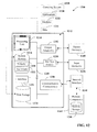
- FIG. 2 is a block diagram of an example TOF sensor device 202 according to one or more embodiments of this disclosure.
- FIG. 2 depicts certain functional components as residing on TOF sensor device 202, it is to be appreciated that one or more of the functional components illustrated in FIG. 2 may reside on a separate device relative to TOF sensor device 202 in some embodiments.
- Aspects of the systems, apparatuses, or processes explained in this disclosure can constitute machine-executable components embodied within machine(s), e.g., embodied in one or more computer-readable mediums (or media) associated with one or more machines.
- Such components when executed by one or more machines, e.g., computer(s), computing device(s), automation device(s), virtual machine(s), etc., can cause the machine(s) to perform the operations described.
- TOF sensor device 202 can include an illumination component 204, a pixel array component 206, a waveform reconstruction component 208, a distance determination component 210, a waveform analysis component 212, a hazard analysis and decision component 214, one or more processors 216, and memory 218.
- one or more of the illumination component 204, pixel array component 206, waveform reconstruction component 208, distance determination component 210, waveform analysis component 212, hazard analysis and decision component 214, the one or more processors 216, and memory 218 can be electrically and/or communicatively coupled to one another to perform one or more of the functions of the TOF sensor device 202.
- components 204, 206, 208, 210, 212, and 214 can comprise software instructions stored on memory 218 and executed by processor(s) 216.
- TOF sensor device 202 may also interact with other hardware and/or software components not depicted in FIG. 2 .
- processor(s) 216 may interact with one or more external user interface devices, such as a keyboard, a mouse, a display monitor, a touchscreen, another sensor, a network, a safety device, or other such interface devices.
- Illumination component 204 can be configured to control emission of light by the sensor device.
- TOF sensor device 202 may comprise a laser, light emitting diode (LED), remote phosphor, or other type of light source under the control of illumination component 204.
- illumination component 204 emits periodic light pulses directed to the viewing field, so that time-of-flight information can be generated by the TOF sensor device 202 based on the reflected light pulses returned to the sensor's photo-receiver array.
- the pixel array component 206 can be configured to scan the pixels of the TOF sensor device's photo-receiver array and generate pixel array data based on measurement of the electrical outputs generated by the photo-receivers in response to receipt of reflected light pulses from the viewing field.
- the waveform reconstruction component 208 can be configured to, for each pixel of the pixel array, generate a waveform corresponding to a reflected light pulse received at the photo-receiver corresponding to that pixel.
- Distance determination component 210 can be configured to derive distance information for each pixel based on the waveforms constructed by the waveform reconstruction component 208, and generate a depth map for the viewing area based on the distance information.
- the waveform analysis component 212 can be configured to analyze the reconstructed waveform signal to, for example, identify specific waveform patterns or filter specific pulses considered not relevant for the depth map data.
- the hazard analysis and decision component 214 can be configured to control one or more sensor outputs based on results generated by the distance determination component 210 and the waveform analysis component 212.
- a safety action e.g., removing power from a hazardous machine, switching an industrial system to a safe operating mode, etc.
- sending a feedback message e.g., a display device, e.g., a human-machine interface, a personal mobile device, etc.
- sending depth map data to an on-board computer in a mobile vehicle, or other such output.
- the one or more processors 216 can perform one or more of the functions described herein with reference to the systems and/or methods disclosed.
- Memory 218 can be a computer-readable storage medium storing computer-executable instructions and/or information for performing the functions described herein with reference to the systems and/or methods disclosed.
- FIG. 3 is a block diagram illustrating components of the TOF sensor device 202 according to one or more embodiments.
- illumination component 204 controls emission of LED, laser light, or remote phosphor pulses to the viewing field via lens element 306.
- illumination component 204 may project a wide beam of light pulses (e.g., a cone-shaped beam) over the viewing field (e.g., a cone-shaped beam).
- Receiver lens element 308 receives light pulses reflected from the viewing field and directs the reflected light pulses to a photo-receiver array 310, which generates respective electrical outputs for each pixel of the array as a function of the intensity of the light pulse received at each photo-receiver.
- Pixel array component 206 performs a readout of the photo-receiver array 310 at regular intervals to obtain samples of the voltage output data for each pixel for analysis.
- the sampled information is provided to waveform reconstruction component 208, which reconstitutes the waveforms corresponding to the reflected light pulses received at the photo-receiver array 310 using techniques described in more detail below.
- distance determination component 210 can determine a distance value associated with each pixel, and additional analysis can be conducted by waveform analysis component 212.
- the distance value represents the distance of the object or surface corresponding to the pixel from the TOF sensor device, and can be determined by identifying the front edge of the returned light pulse from the waveform data, which represents the time at which the light pulse was received at the receiver lens element 308.
- the distance determination component 210 can then compare this time with the time at which the emitted light pulse was sent by the illumination component 204. The difference between the two times represents the time-of-flight for the pulse, from which the distance information for the pixel can be derived.
- the TOF sensor can generate depth map data 312, which can be used to create a 3D point cloud 302 of the viewing field.
- hazard analysis and decision component 214 can be instructed to generate a suitable control or message output based on the depth map data and additional waveform analysis.
- FIG. 4 is a timing chart 402 that plots a representation of a transmitted light pulse 404 sent by the TOF sensor device's lens element 306 and a waveform for a corresponding reflected light pulse 406 subsequently received at the photo-receiver.
- the difference Tdiff between the time Txpulse at which light pulse 404 begins emission and time Rxpulse when the reflected light pulse 406 begins arriving at the photo-receiver is proportional to the distance (from the TOF sensor) of a surface from which the transmitted light pulse 404 was reflected.
- the start and stop times for the transmitted pulse can be accurately measured by the sensor's internal components, yielding a substantially square wave having a length corresponding to the duration of the transmitted pulse.
- the waveform for the reflected light pulse 406 is determined by sampling the photo-receiver at which the return pulse is received, and applying curve-fitting on the sampled values to yield the waveform.
- FIG. 5 is a graph 502 illustrating a representation of the reflected light pulse 406 sampled at k samples/second (where k is an integer) to yield a number of sampled points 504 spaced apart in time by 1/k seconds.
- k samples/second represents a desired sampling rate that ensures accurate reconstitution of the reflected light pulse waveform.
- SNR signal-to-noise ratio
- One or more embodiments of the TOF sensor device described herein employ waveform reconstruction techniques capable of reconstructing the waveform at the desired sample rate of k samples/second. The TOF sensor achieves this by executing a number of accumulation cycles during which the electrical output of the photo-receivers in response to incident light is read and integrated over controlled exposure times, referred to herein as integration periods, to yield accumulated values.
- FIG. 6 illustrates a graph 602 of a waveform 604 representing the electrical output of a photo-receiver over time during an example integration period.
- the electrical output is a function of the intensity of light incident on the surface of the photo-receiver.
- the entirety of a reflected light pulse was received at the photo-receiver during the integration period, such that the peak, rising edge, and falling edge of the waveform 604 fall within the integration period (as will be explained in more detail below, this will not be the case for all accumulation cycles, since the integration window is shifted for each accumulation cycle).
- the waveform reconstruction component 208 executes a number of accumulation cycles. For multiple integration cycles of each accumulation cycle, the electrical output of the photo-receivers in response to incident light is read and integrated over the integration period, and the integration results for the multiple integration cycles are added together to yield accumulated values. For each accumulation cycle, the start time of the integration period is delayed by a delay period relative to the start time of the integration period for the previous accumulation cycle, exposing the photo-receiver to a different portion of the reflected light pulse waveform relative to the previous accumulation cycle. The differences between pairs of consecutive accumulation values are then obtained to yield a set of time-based sampled values for the reflected waveform, which can be used to accurately reconstruct the reflected waveform (e.g. by interpolating between the sampled values).
- FIG. 7 is a timing diagram for a portion of first accumulation cycle (Accumulation Cycle #1).
- the illumination component 204 of the TOF sensor emits a train of transmitted light pulses 702 toward a viewing field.
- the light pulses are transmitted within a rate P (pulses per second).
- the accumulation cycle comprises N integration cycles or accumulations, with each integration cycle corresponding to one of the transmitted light pulses 702.
- the waveform reconstruction component 208 initiates a first integration period 704A, where the start time of the integration period is a function of the start time of the first transmitted pulse 702A.
- the waveform reconstruction component 208 initiates each integration period 704 synchronized with the start of the transmitted light pulses 702, ensuring that the relative timing between the transmitted pulse and the integration period remains fixed for each of N integration cycles of the accumulation cycle.
- the waveform reconstruction component 208 then begins a second accumulation cycle (Accumulation Cycle #2).
- FIG. 8 is a timing diagram illustrating the second accumulation cycle.
- the waveform reconstruction component 208 begins Accumulation Cycle #2 by initiating an integration period 804A lasting T_I seconds for a first integration cycle n, during which the incident light energy exposed to the photo-receiver is integrated.
- the start time for the integration period 804A is delayed relative to the start time of the integration period 704A for Accumulation Cycle #1 by 1/k seconds (that is, whereas the integration period for the first accumulation cycle was initiated at Txpulse1 - T_I + 1/k, the integration period for the second accumulation cycle is initiated at Txpulse1 - T_I + 2/k).
- the waveform reconstruction component 208 can calculate a value of the first sample point of the waveform by subtracting the accumulated value of the Accumulation Cycle #2 (Accumulation #2) from the accumulated value of Accumulation Cycle #1 (Accumulation #1). This difference value represents the first sampled value of the waveform for the reflected pulse between time Txpulse and Txpulse + 1/k.
- Waveform reconstruction component 208 repeats this sequence by executing additional accumulation cycles, with the start time of each integration period delayed by 1/k relative to the previous cycle.
- Waveform reconstruction component 208 can reconstruct the entire waveform corresponding to the reflected light pulse 904 by repeating the above T_I/k times. With a sufficient number of sampled values obtained using equations (1) - (3), a plot similar to that depicted in FIG. 5 can be obtained, and the waveform for the reflected light pulse can be accurately reconstituted; e.g., by applying curve-fitting techniques to the sampled values.
- FIG. 10 is a diagram illustrating the derivation of sample points for a reflected light pulse waveform using the techniques described above.
- FIG. 10 only depicts three accumulation cycles, with only two integration cycles per cycle. Also, the reflected light pulses corresponding to each transmitted pulse is not shown in FIG. 10 .
- TOF sensor emits transmitted pulse 1002 within a period P.
- the instantaneous electrical output q of the photo-receiver is integrated over respective two integration periods, and the results are added to yield Accumulation #1.
- the integration period is delayed by 1/k relative to the integration period of the first accumulation cycle, and the process is repeated using the delayed integration period to yield Accumulation #2.
- the integration period is delayed by 1/k relative to the integration period of the second accumulation cycle, and the process is repeated to yield Accumulation #3.
- the difference between Accumulation #1 and Accumulation #2 yields sample point #1, and the difference between Accumulation #2 and Accumulation #2 yields sample point #2.
- Repeating this for additional accumulation cycles yields a set of sample points at intervals 1/k seconds for a waveform corresponding to a received light pulse reflected in response to emission of the transmitted light pulse.
- the waveform reconstruction component 208 may be configured to begin the accumulation period before the emitted light pulse is sent.
- the start time T_0 of the accumulation cycle may be set to begin at T_I - 1/k seconds before the rising edge of the emitted light pulse.
- the waveform reconstruction component 208 can measure the background light present in the accumulation during the period before the light pulse is sent, and use this information to improve the SNR.
- one or more parameters of the TOF sensor device 202 can be configured as needed to suit the needs of a particular application.
- the total integration time T_I determines the range for which objects within the viewing field will be detected. Accordingly, one or more embodiments of the TOF sensor device 202 allow the user to adjust this integration time as needed to optimize the operating range for the as required by the monitoring application.
- the delay between accumulation cycles (that is, the delay between the completion of accumulation cycle #i and accumulation cycle #i+1) can be made variable.
- the delay between accumulation cycles can be set automatically by the waveform reconstruction component 208, e.g., as a function of object distance or range or as a function of the signal to noise ratio.
- the waveform reconstruction component 208 may set the delay between accumulation cycles to be shorter in direct proportion to the closeness of an object to the TOF sensor device. Since a shorter delay between accumulation cycles results in finer distance resolution, distance resolution is made finer the closer the object is to the TOF sensor, and resolution is decreased for objects that are farther away. Thus, resolution of the time delay - and consequently the resolution of the distance - is automatically controlled as a function of range. In this way, the waveform reconstruction component 208 is able to substantially optimize the trade-off between object distance and resolution.
- FIGs 11A-11B illustrate a methodology in accordance with one or more embodiments of the subject application. While, for purposes of simplicity of explanation, the one or more methodologies shown herein are shown and described as a series of acts, it is to be understood and appreciated that the subject innovation is not limited by the order of acts, as some acts may, in accordance therewith, occur in a different order and/or concurrently with other acts from that shown and described herein. For example, those skilled in the art will understand and appreciate that a methodology could alternatively be represented as a series of interrelated states or events, such as in a state diagram. Moreover, not all illustrated acts may be required to implement a methodology in accordance with the innovation.
- interaction diagram(s) may represent methodologies, or methods, in accordance with the subject disclosure when disparate entities enact disparate portions of the methodologies.
- two or more of the disclosed example methods can be implemented in combination with each other, to accomplish one or more features or advantages described herein.
- FIG. 11A illustrates a first part of an example methodology 1100A for reconstructing a waveform corresponding to a reflected light pulse incident on a photo-receiver of a TOF sensor device.
- electrical output of a photo-receiver of a TOF sensor is accumulated and integrated.
- a reflected light is received at the photo-receiver.
- the value of the electrical output generated by the photo-receiver during the integration period (that is, from time T_0 to (T_0 + T_I)) is integrated to yield an integrated value.
- step 1118 When it is determined at step 1118 that all N integration cycles for the current accumulation cycle have completed, the methodology moves to step 1120, where the sum of the accumulated values determined at step 1114 for all N cycles is stored as accumulated value i. This value is represented by equation (1) above.
- step 1122 a determination is made regarding whether all accumulation cycles have completed. In some embodiments, the number of accumulation cycles to be run is equal to T_I/k, where k is a desired sampling frequency for the waveform (in samples/second).
- step 1122 If it is determined at step 1122 that additional accumulation cycles are to be run, the methodology moves to step 1124, where accumulation cycle pointer i is incremented (representing the next accumulation cycle), and at 1126 a delay of 1/k seconds is added to the time T_0 at which the integration period for the next cycle is to begin.
- the methodology then returns to step 1102, where a new integration cycle begins and steps 1102-1120 are carried out for the subsequent cycle using the delayed value of T_0 to determine the start and stop time for the integration period within the cycle. Steps 1102-1120 are repeated until all accumulation cycles have completed (e.g., T_I/k accumulation cycles), resulting in a set of accumulated values respectively corresponding to the accumulation cycles.
- accumulation cycle pointer i is set to 1.
- waveform sample value (i) is set equal to the accumulation value(i) minus accumulation value (i+1). That is, a given waveform sample value is calculated by determining the difference between accumulation values obtained at step 1120 for two consecutive accumulation cycles, as represented by equation (3) above.
- step 1132 a determination is made regarding whether i is equal to the total samples to be obtained for the waveform. If all samples have not been obtained, the pointer i is incremented at step 1134 and the methodology returns to step 1130 to determine the next waveform sample value. When it is determined at step 1132 that all samples have been obtained, the methodology moves to step 1136, where waveform data for the reflected light pulse incident on the photo-receiver is obtained by interpolating between the sampled points (e.g., using curve-fitting techniques).
- waveform shape analysis is performed on the waveform data to identify specific waveform patterns. Additionally, filtering of the waveform may be performed based on a result of the waveform shape analysis.
- the waveform data may be filtered or ignored.
- the difference between Rxpulse (the time of arrival of the reflected waveform) and Txpulse (the time at which the emitted light pulse was sent) is determined based on the waveform data.
- distance data for a pixel corresponding to the photo-receiver is determined based on the difference determined at step 1140.
- Embodiments, systems, and components described herein, as well as industrial control systems and industrial automation environments in which various aspects set forth in the subject specification can be carried out can include computer or network components such as servers, clients, programmable logic controllers (PLCs), automation controllers, communications modules, mobile computers, wireless components, control components and so forth which are capable of interacting across a network.
- Computers and servers include one or more processors-electronic integrated circuits that perform logic operations employing electric signals-configured to execute instructions stored in media such as random access memory (RAM), read only memory (ROM), a hard drives, as well as removable memory devices, which can include memory sticks, memory cards, flash drives, external hard drives, and so on.
- the term PLC or automation controller as used herein can include functionality that can be shared across multiple components, systems, and/or networks.
- one or more PLCs or automation controllers can communicate and cooperate with various network devices across the network. This can include substantially any type of control, communications module, computer, Input/Output (I/O) device, sensor, actuator, and human machine interface (HMI) that communicate via the network, which includes control, automation, and/or public networks.
- the PLC or automation controller can also communicate to and control various other devices such as standard or safety-rated I/O modules including analog, digital, programmed/intelligent I/O modules, other programmable controllers, communications modules, sensors, actuators, output devices, and the like.
- the network can include public networks such as the internet, intranets, and automation networks such as control and information protocol (CIP) networks including DeviceNet, ControlNet, Ethernet/IP, safety networks (e.g., CIP safety), etc.
- CIP control and information protocol
- Other networks include Ethernet, DH/DH+, Remote I/O, Fieldbus, Modbus, Profibus, CAN, wireless networks, serial protocols, and so forth.
- the network devices can include various possibilities (hardware and/or software components). These include components such as switches with virtual local area network (VLAN) capability, LANs, WANs, proxies, gateways, routers, firewalls, virtual private network (VPN) devices, servers, clients, computers, configuration tools, monitoring tools, and/or other devices.
- VLAN virtual local area network
- WANs wide area network
- proxies gateways
- routers virtual private network
- VPN virtual private network
- FIGs. 12 and 13 are intended to provide a brief, general description of a suitable environment in which the various aspects of the disclosed subject matter may be implemented.
- an example environment 1210 for implementing various aspects of the aforementioned subject matter includes a computer 1212.
- the computer 1212 includes a processing unit 1214, a system memory 1216, and a system bus 1218.
- the system bus 1218 couples system components including, but not limited to, the system memory 1216 to the processing unit 1214.
- the processing unit 1214 can be any of various available processors. Multi-core microprocessors and other multiprocessor architectures also can be employed as the processing unit 1214.
- the system bus 1218 can be any of several types of bus structure(s) including the memory bus or memory controller, a peripheral bus or external bus, and/or a local bus using any variety of available bus architectures including, but not limited to, 8-bit bus, Industrial Standard Architecture (ISA), Micro-Channel Architecture (MSA), Extended ISA (EISA), Intelligent Drive Electronics (IDE), VESA Local Bus (VLB), Peripheral Component Interconnect (PCI), Universal Serial Bus (USB), Advanced Graphics Port (AGP), Personal Computer Memory Card International Association bus (PCMCIA), and Small Computer Systems Interface (SCSI).
- ISA Industrial Standard Architecture
- MSA Micro-Channel Architecture
- EISA Extended ISA
- IDE Intelligent Drive Electronics
- VLB VESA Local Bus
- PCI Peripheral Component Interconnect
- USB Universal Serial Bus
- AGP Advanced Graphics Port
- PCMCIA Personal Computer Memory Card International Association bus
- SCSI Small Computer Systems Interface
- the system memory 1216 includes volatile memory 1220 and nonvolatile memory 1222.
- the basic input/output system (BIOS) containing the basic routines to transfer information between elements within the computer 1212, such as during start-up, is stored in nonvolatile memory 1222.
- nonvolatile memory 1222 can include read only memory (ROM), programmable ROM (PROM), electrically programmable ROM (EPROM), electrically erasable PROM (EEPROM), or flash memory.
- Volatile memory 1220 includes random access memory (RAM), which acts as external cache memory.
- RAM is available in many forms such as synchronous RAM (SRAM), dynamic RAM (DRAM), synchronous DRAM (SDRAM), double data rate SDRAM (DDR SDRAM), enhanced SDRAM (ESDRAM), Synchlink DRAM (SLDRAM), and direct Rambus RAM (DRRAM).
- SRAM synchronous RAM
- DRAM dynamic RAM
- SDRAM synchronous DRAM
- DDR SDRAM double data rate SDRAM
- ESDRAM enhanced SDRAM
- SLDRAM Synchlink DRAM
- DRRAM direct Rambus RAM
- Computer 1212 also includes removable/non-removable, volatile/nonvolatile computer storage media.
- FIG. 12 illustrates, for example a disk storage 1224.
- Disk storage 1224 includes, but is not limited to, devices like a magnetic disk drive, floppy disk drive, tape drive, Jaz drive, Zip drive, LS-100 drive, flash memory card, or memory stick.
- disk storage 1224 can include storage media separately or in combination with other storage media including, but not limited to, an optical disk drive such as a compact disk ROM device (CD-ROM), CD recordable drive (CD-R Drive), CD rewritable drive (CD-RW Drive) or a digital versatile disk ROM drive (DVD-ROM).
- CD-ROM compact disk ROM device
- CD-R Drive CD recordable drive
- CD-RW Drive CD rewritable drive
- DVD-ROM digital versatile disk ROM drive
- a removable or non-removable interface is typically used such as interface 1526.
- FIG. 12 describes software that acts as an intermediary between users and the basic computer resources described in suitable operating environment 1210.
- Such software includes an operating system 1228.
- Operating system 1228 which can be stored on disk storage 1224, acts to control and allocate resources of the computer 1212.
- System applications 1230 take advantage of the management of resources by operating system 1228 through program modules 1232 and program data 1234 stored either in system memory 1216 or on disk storage 1224. It is to be appreciated that one or more embodiments of the subject disclosure can be implemented with various operating systems or combinations of operating systems.
- Input devices 1236 include, but are not limited to, a pointing device such as a mouse, trackball, stylus, touch pad, keyboard, microphone, joystick, game pad, satellite dish, scanner, TV tuner card, digital camera, digital video camera, web camera, and the like. These and other input devices connect to the processing unit 1214 through the system bus 1218 via interface port(s) 1238.
- Interface port(s) 1238 include, for example, a serial port, a parallel port, a game port, and a universal serial bus (USB).
- Output device(s) 1240 use some of the same type of ports as input device(s) 1236.
- a USB port may be used to provide input to computer 1212, and to output information from computer 1212 to an output device 1240.
- Output adapters 1242 are provided to illustrate that there are some output devices 1240 like monitors, speakers, and printers, among other output devices 1240, which require special adapters.
- the output adapters 1242 include, by way of illustration and not limitation, video and sound cards that provide a means of connection between the output device 1240 and the system bus 1218. It should be noted that other devices and/or systems of devices provide both input and output capabilities such as remote computer(s) 1244.
- Computer 1212 can operate in a networked environment using logical connections to one or more remote computers, such as remote computer(s) 1244.
- the remote computer(s) 1244 can be a personal computer, a server, a router, a network PC, a workstation, a microprocessor based appliance, a peer device or other common network node and the like, and typically includes many or all of the elements described relative to computer 1212. For purposes of brevity, only a memory storage device 1546 is illustrated with remote computer(s) 1244.
- Remote computer(s) 1244 is logically connected to computer 1212 through a network interface 1248 and then physically connected via communication connection 1250.
- Network interface 1248 encompasses communication networks such as local-area networks (LAN) and wide-area networks (WAN).
- LAN technologies include Fiber Distributed Data Interface (FDDI), Copper Distributed Data Interface (CDDI), Ethernet/IEEE 802.3, Token Ring/IEEE 802.5 and the like.
- WAN technologies include, but are not limited to, point-to-point links, circuit switching networks like Integrated Services Digital Networks (ISDN) and variations thereon, packet switching networks, and Digital Subscriber Lines (DSL).
- ISDN Integrated Services Digital Networks
- DSL Digital Subscriber Lines
- Communication connection(s) 1250 refers to the hardware/software employed to connect the network interface 1248 to the system bus 1218. While communication connection 1250 is shown for illustrative clarity inside computer 1212, it can also be external to computer 1212.
- the hardware/software necessary for connection to the network interface 1248 includes, for exemplary purposes only, internal and external technologies such as, modems including regular telephone grade modems, cable modems and DSL modems, ISDN adapters, and Ethernet cards.
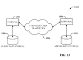
- FIG. 13 is a schematic block diagram of a sample computing environment 1300 with which the disclosed subject matter can interact.
- the sample computing environment 1300 includes one or more client(s) 1302.
- the client(s) 1302 can be hardware and/or software (e.g., threads, processes, computing devices).
- the sample computing environment 1300 also includes one or more server(s) 1304.
- the server(s) 1304 can also be hardware and/or software (e.g., threads, processes, computing devices).
- the servers 1304 can house threads to perform transformations by employing one or more embodiments as described herein, for example.
- One possible communication between a client 1302 and servers 1304 can be in the form of a data packet adapted to be transmitted between two or more computer processes.
- the sample computing environment 1300 includes a communication framework 1306 that can be employed to facilitate communications between the client(s) 1302 and the server(s) 1304.
- the client(s) 1302 are operably connected to one or more client data store(s) 1308 that can be employed to store information local to the client(s) 1302.
- the server(s) 1304 are operably connected to one or more server data store(s) 1310 that can be employed to store information local to the servers 1304.
- the terms (including a reference to a "means") used to describe such components are intended to correspond, unless otherwise indicated, to any component which performs the specified function of the described component (e.g., a functional equivalent), even though not structurally equivalent to the disclosed structure, which performs the function in the herein illustrated exemplary aspects of the disclosed subject matter.
- the disclosed subject matter includes a system as well as a computer-readable medium having computer-executable instructions for performing the acts and/or events of the various methods of the disclosed subject matter.
- exemplary is used to mean serving as an example, instance, or illustration. Any aspect or design described herein as "exemplary” is not necessarily to be construed as preferred or advantageous over other aspects or designs. Rather, use of the word exemplary is intended to present concepts in a concrete fashion.
- Computer readable media can include but are not limited to magnetic storage devices (e.g., hard disk, floppy disk, magnetic strips...), optical disks [e.g., compact disk (CD), digital versatile disk (DVD)...], smart cards, and flash memory devices (e.g., card, stick, key drive).
- magnetic storage devices e.g., hard disk, floppy disk, magnetic strips
- optical disks e.g., compact disk (CD), digital versatile disk (DVD)...
- smart cards e.g., card, stick, key drive
Applications Claiming Priority (2)
| Application Number | Priority Date | Filing Date | Title |
|---|---|---|---|
| US201462000486P | 2014-05-19 | 2014-05-19 | |
| US14/609,340 US9921300B2 (en) | 2014-05-19 | 2015-01-29 | Waveform reconstruction in a time-of-flight sensor |
Publications (3)
| Publication Number | Publication Date |
|---|---|
| EP2947477A2 true EP2947477A2 (de) | 2015-11-25 |
| EP2947477A3 EP2947477A3 (de) | 2015-12-16 |
| EP2947477B1 EP2947477B1 (de) | 2024-01-24 |
Family
ID=53181159
Family Applications (1)
| Application Number | Title | Priority Date | Filing Date |
|---|---|---|---|
| EP15168237.4A Active EP2947477B1 (de) | 2014-05-19 | 2015-05-19 | Wellenformrekonstruktion in einem laufzeitsensor |
Country Status (3)
| Country | Link |
|---|---|
| US (1) | US9921300B2 (de) |
| EP (1) | EP2947477B1 (de) |
| CN (1) | CN105093206B (de) |
Cited By (2)
| Publication number | Priority date | Publication date | Assignee | Title |
|---|---|---|---|---|
| EP3936895A4 (de) * | 2019-04-09 | 2022-03-02 | Huawei Technologies Co., Ltd. | Distanzmessverfahren, gerät und vorrichtung |
| US11513200B2 (en) | 2017-02-21 | 2022-11-29 | Sony Semiconductor Solutions Corporation | Distance measuring device and distance measuring method |
Families Citing this family (17)
| Publication number | Priority date | Publication date | Assignee | Title |
|---|---|---|---|---|
| US9866816B2 (en) | 2016-03-03 | 2018-01-09 | 4D Intellectual Properties, Llc | Methods and apparatus for an active pulsed 4D camera for image acquisition and analysis |
| US10627494B2 (en) | 2016-09-16 | 2020-04-21 | Analog Devices, Inc. | Interference handling in time-of-flight depth sensing |
| WO2018053292A1 (en) * | 2016-09-16 | 2018-03-22 | Analog Devices, Inc. | Interference handling in time-of-flight depth sensing |
| CN108209867B (zh) * | 2016-12-15 | 2022-03-18 | 松下知识产权经营株式会社 | 摄像装置 |
| US10389957B2 (en) * | 2016-12-20 | 2019-08-20 | Microsoft Technology Licensing, Llc | Readout voltage uncertainty compensation in time-of-flight imaging pixels |
| EP3367130A1 (de) * | 2017-02-22 | 2018-08-29 | STMicroelectronics (Research & Development) Limited | Integration einer tiefenkartenvorrichtung zur adaptiven beleuchtungssteuerung |
| JP6852481B2 (ja) * | 2017-03-15 | 2021-03-31 | オムロン株式会社 | 光電センサ |
| EP3388864A1 (de) * | 2017-04-10 | 2018-10-17 | Bea S.A. | Verfahren zur erkennung von menschlichen körpern und erkennungssensor für menschlichen körper |
| DE102017207317B4 (de) * | 2017-05-02 | 2022-03-03 | Fraunhofer-Gesellschaft zur Förderung der angewandten Forschung e.V. | Vorrichtung zur Ermittlung eines Abstands zu einem Objekt sowie entsprechendes Verfahren |
| US10852402B2 (en) * | 2017-12-07 | 2020-12-01 | Texas Instruments Incorporated | Phase anti-aliasing using spread-spectrum techniques in an optical distance measurement system |
| WO2020037167A1 (en) | 2018-08-17 | 2020-02-20 | Sense Photonics, Inc. | Methods and systems for increasing the range of time-of-flight systems by unambiguous range toggling |
| WO2020042166A1 (zh) * | 2018-08-31 | 2020-03-05 | 深圳市汇顶科技股份有限公司 | 基于飞行时间的测距方法和测距系统 |
| CN109255095B (zh) * | 2018-08-31 | 2022-09-20 | 腾讯科技(深圳)有限公司 | Imu数据的积分方法、装置、计算机可读介质及电子设备 |
| CN111398976B (zh) * | 2020-04-01 | 2022-08-23 | 宁波飞芯电子科技有限公司 | 探测装置及方法 |
| CN111580125B (zh) * | 2020-05-28 | 2022-09-09 | Oppo广东移动通信有限公司 | 飞行时间模组及其控制方法、电子设备 |
| CN113791422B (zh) * | 2020-12-04 | 2024-04-09 | 神盾股份有限公司 | 飞时测距装置以及飞时测距方法 |
| CN113329146B (zh) * | 2021-04-25 | 2022-06-03 | 北京大学 | 一种脉冲相机模拟方法与装置 |
Family Cites Families (63)
| Publication number | Priority date | Publication date | Assignee | Title |
|---|---|---|---|---|
| US4967317A (en) | 1988-06-16 | 1990-10-30 | Genlyte | Exit sign |
| US5029008A (en) | 1990-05-04 | 1991-07-02 | Bran Ferren | Apparatus for identifying television monitors |
| US5075823A (en) | 1990-11-16 | 1991-12-24 | Video One Systems Ltd. | Color correcting system for fluorescent lighting |
| EP0835460B1 (de) | 1995-06-22 | 2006-03-08 | 3DV Systems Ltd. | Verbesserte optische kamera zur entfernungsmessung |
| FR2756129B1 (fr) | 1996-11-15 | 1999-07-09 | Sagem | Camera video a deviateur d'augmentation de resolution |
| US6517213B1 (en) | 1997-03-31 | 2003-02-11 | Idec Izumi Corporation | Indicator device and illumination device |
| US6235148B1 (en) | 1999-03-05 | 2001-05-22 | Billy F. Courson, Jr. | Chemiluminescent photo-curable adhesive curing and bonding system |
| US7200246B2 (en) | 2000-11-17 | 2007-04-03 | Honeywell International Inc. | Object detection |
| DE10113880B4 (de) | 2001-03-21 | 2004-04-29 | T-Mobile Deutschland Gmbh | Verfahren zur Komprimierung und Dekomprimierung von Videodaten |
| US7768549B2 (en) | 2001-06-08 | 2010-08-03 | Honeywell International Inc. | Machine safety system with mutual exclusion zone |
| DE50208355D1 (de) | 2001-08-06 | 2006-11-16 | Siemens Ag | Verfahren und vorrichtung zur aufnahme eines dreidimensionalen abstandsbildes |
| WO2003089063A1 (en) | 2002-04-16 | 2003-10-30 | Lumerx, Inc | Chemiluminescent light source using visible light for biotherapy |
| JP2004093623A (ja) | 2002-08-29 | 2004-03-25 | Olympus Corp | 照明装置及びそれを用いた表示装置 |
| US7729511B2 (en) | 2002-09-24 | 2010-06-01 | Pilz Gmbh & Co. Kg | Method and device for safeguarding a hazardous area |
| US7157839B2 (en) | 2003-01-27 | 2007-01-02 | 3M Innovative Properties Company | Phosphor based light sources utilizing total internal reflection |
| US7091661B2 (en) | 2003-01-27 | 2006-08-15 | 3M Innovative Properties Company | Phosphor based light sources having a reflective polarizer |
| DE10345948B4 (de) | 2003-10-02 | 2018-08-23 | Robert Bosch Gmbh | Verfahren zur Bewertung und zeitlichen Stabilisierung von Klassifizierungsergebnissen |
| US8131020B2 (en) | 2004-05-20 | 2012-03-06 | Mcmaster University | Method for controlling the appearance of products and process performance by image analysis |
| US8113695B2 (en) | 2005-02-04 | 2012-02-14 | Adac Plastics, Inc. | Trim component with concealed indicium |
| US7532311B2 (en) | 2005-04-06 | 2009-05-12 | Lockheed Martin Coherent Technologies, Inc. | Efficient lidar with flexible target interrogation pattern |
| US8128272B2 (en) | 2005-06-07 | 2012-03-06 | Oree, Inc. | Illumination apparatus |
| US7355179B1 (en) | 2005-07-30 | 2008-04-08 | Rockwell Collins, Inc. | Scene imaging system integrity monitor and method thereof |
| DE102005056265A1 (de) | 2005-11-14 | 2007-05-16 | Pilz Gmbh & Co Kg | Vorrichtung und Verfahren zum Überwachen eines Raumbereichs, insbesondere zum Absichern eines Gefahrenbereichs einer automatisiert arbeitenden Anlage |
| WO2007099611A1 (ja) | 2006-02-28 | 2007-09-07 | Fujitsu Limited | 反射光検出装置、並びに、反射特性判断装置、及び、物体検出装置 |
| US8942426B2 (en) | 2006-03-02 | 2015-01-27 | Michael Bar-Am | On-train rail track monitoring system |
| DE102006029025A1 (de) | 2006-06-14 | 2007-12-27 | Iris-Gmbh Infrared & Intelligent Sensors | Vorrichtung und Verfahren zur Abstandsbestimmung |
| US7471376B2 (en) | 2006-07-06 | 2008-12-30 | Canesta, Inc. | Method and system for fast calibration of three-dimensional (3D) sensors |
| DE102006048166A1 (de) | 2006-08-02 | 2008-02-07 | Daimler Ag | Verfahren zur Beobachtung einer Person in einem industriellen Umfeld |
| US8333907B2 (en) | 2007-01-17 | 2012-12-18 | Utc Fire & Security Corporation | Articles using persistent phosphors |
| WO2008152647A2 (en) | 2007-06-15 | 2008-12-18 | Ben Gurion University Of The Negev Research And Development Authority | Three-dimensional imaging method and apparatus |
| US8325245B2 (en) | 2007-09-25 | 2012-12-04 | Rockwell Automation Technologies, Inc. | Apparatus and methods for use of infra-red light in camera applications |
| US8310655B2 (en) | 2007-12-21 | 2012-11-13 | Leddartech Inc. | Detection and ranging methods and systems |
| WO2009094043A1 (en) | 2008-01-21 | 2009-07-30 | Kameraflage Inc. | Methods and systems for displaying messages in a wide-spectrum display |
| US7995854B2 (en) | 2008-03-28 | 2011-08-09 | Tandent Vision Science, Inc. | System and method for identifying complex tokens in an image |
| HUE039300T2 (hu) | 2008-11-25 | 2018-12-28 | Tetravue Inc | Rendszerek és eljárások nagyfelbontású háromdimenziós képalkotáshoz |
| US8905610B2 (en) | 2009-01-26 | 2014-12-09 | Flex Lighting Ii, Llc | Light emitting device comprising a lightguide film |
| US8253564B2 (en) | 2009-02-19 | 2012-08-28 | Panasonic Corporation | Predicting a future location of a moving object observed by a surveillance device |
| US8254760B2 (en) | 2009-08-28 | 2012-08-28 | Apple Inc. | Pixel analysis and frame alignment for background frames |
| US8253792B2 (en) | 2009-08-28 | 2012-08-28 | GM Global Technology Operations LLC | Vision system for monitoring humans in dynamic environments |
| KR101565969B1 (ko) | 2009-09-01 | 2015-11-05 | 삼성전자주식회사 | 깊이 정보를 추정할 수 있는 방법과 장치, 및 상기 장치를 포함하는 신호 처리 장치 |
| US20110109617A1 (en) | 2009-11-12 | 2011-05-12 | Microsoft Corporation | Visualizing Depth |
| JP2011169701A (ja) | 2010-02-17 | 2011-09-01 | Sanyo Electric Co Ltd | 物体検出装置および情報取得装置 |
| US9143843B2 (en) | 2010-12-09 | 2015-09-22 | Sealed Air Corporation | Automated monitoring and control of safety in a production area |
| US9189949B2 (en) | 2010-12-09 | 2015-11-17 | Sealed Air Corporation (Us) | Automated monitoring and control of contamination in a production area |
| CN102447882A (zh) | 2010-10-13 | 2012-05-09 | 鸿富锦精密工业(深圳)有限公司 | 时间飞行摄影机装置及利用其进行影像监控的方法 |
| US8983121B2 (en) | 2010-10-27 | 2015-03-17 | Samsung Techwin Co., Ltd. | Image processing apparatus and method thereof |
| US9599461B2 (en) | 2010-11-16 | 2017-03-21 | Ectoscan Systems, Llc | Surface data acquisition, storage, and assessment system |
| EP2772676B1 (de) | 2011-05-18 | 2015-07-08 | Sick Ag | 3D-Kamera und Verfahren zur dreidimensionalen Überwachung eines Überwachungsbereichs |
| US8421037B2 (en) | 2011-06-10 | 2013-04-16 | Rockwell Automation Technologies, Inc. | System and method for reduction of optical noise |
| US8480246B2 (en) | 2011-06-10 | 2013-07-09 | Rockwell Automation Technologies, Inc. | System and method for reduction of optical noise |
| EP2733928B1 (de) | 2011-07-12 | 2021-09-22 | Samsung Electronics Co., Ltd. | Vorrichtung und verfahren zur verarbeitung von trübungen |
| JP6193227B2 (ja) | 2011-07-12 | 2017-09-06 | サムスン エレクトロニクス カンパニー リミテッド | ブラー処理装置及び方法 |
| EP2754125B1 (de) | 2011-10-14 | 2017-01-18 | Omron Corporation | Verfahren und vorrichtung zur projektiven volumenüberwachung |
| JP2013101045A (ja) | 2011-11-08 | 2013-05-23 | Fanuc Ltd | 物品の3次元位置姿勢の認識装置及び認識方法 |
| US9530060B2 (en) | 2012-01-17 | 2016-12-27 | Avigilon Fortress Corporation | System and method for building automation using video content analysis with depth sensing |
| US9297935B2 (en) | 2012-01-27 | 2016-03-29 | Rockwell Automation Technologies, Inc. | Method and device for enhancing sensor indication |
| EP2815251B1 (de) | 2012-02-15 | 2017-03-22 | Heptagon Micro Optics Pte. Ltd. | Tof-kamera mit streifenbeleuchtung |
| DE102012102236A1 (de) | 2012-03-16 | 2013-09-19 | Pilz Gmbh & Co. Kg | Verfahren und Vorrichtung zum Absichern eines gefährlichen Arbeitsbereichs einer automatisiert arbeitenden Maschine |
| JP6197291B2 (ja) | 2012-03-21 | 2017-09-20 | 株式会社リコー | 複眼カメラ装置、及びそれを備えた車両 |
| EP2842104B1 (de) | 2012-05-14 | 2016-10-19 | Omron Corporation | Verfahren und vorrichtung zur gewährleistung eines mindestkontrastes für ein maschinenvisionssystem |
| US9002067B2 (en) | 2013-03-28 | 2015-04-07 | Bytelogics Inc. | Systems and methods for detecting blood alcohol level |
| AU2014306018B2 (en) | 2013-08-06 | 2018-05-17 | Bp Corporation North America Inc. | Image-based direct numerical simulation of petrophysical properties under simulated stress and strain conditions |
| US9251598B2 (en) | 2014-04-10 | 2016-02-02 | GM Global Technology Operations LLC | Vision-based multi-camera factory monitoring with dynamic integrity scoring |
-
2015
- 2015-01-29 US US14/609,340 patent/US9921300B2/en active Active
- 2015-05-19 CN CN201510256019.7A patent/CN105093206B/zh active Active
- 2015-05-19 EP EP15168237.4A patent/EP2947477B1/de active Active
Non-Patent Citations (1)
| Title |
|---|
| None |
Cited By (2)
| Publication number | Priority date | Publication date | Assignee | Title |
|---|---|---|---|---|
| US11513200B2 (en) | 2017-02-21 | 2022-11-29 | Sony Semiconductor Solutions Corporation | Distance measuring device and distance measuring method |
| EP3936895A4 (de) * | 2019-04-09 | 2022-03-02 | Huawei Technologies Co., Ltd. | Distanzmessverfahren, gerät und vorrichtung |
Also Published As
| Publication number | Publication date |
|---|---|
| US9921300B2 (en) | 2018-03-20 |
| CN105093206A (zh) | 2015-11-25 |
| US20150331092A1 (en) | 2015-11-19 |
| EP2947477A3 (de) | 2015-12-16 |
| EP2947477B1 (de) | 2024-01-24 |
| CN105093206B (zh) | 2018-01-02 |
Similar Documents
| Publication | Publication Date | Title |
|---|---|---|
| EP2947477B1 (de) | Wellenformrekonstruktion in einem laufzeitsensor | |
| US20220128658A1 (en) | Waveform reconstruction in a time-of-flight sensor | |
| EP3260890B1 (de) | System und verfahren für impulsbasierten empfängerfotosensor | |
| EP3015881B1 (de) | Messung der absoluten entfernung für time-of-flight-sensoren | |
| EP3379291A1 (de) | Bildgebungsvorrichtung und festkörperbildgebungselement dafür | |
| US10725157B1 (en) | Industrial safety sensor | |
| US9696424B2 (en) | Optical area monitoring with spot matrix illumination | |
| EP3572836B1 (de) | Flugzeitsystem und -verfahren unter verwendung mehrerer messsequenzen | |
| EP3572835B1 (de) | Permutation von messkondensatoren in einem flugzeitsensor | |
| US10585176B2 (en) | Pulsed-based time of flight methods and system | |
| US10969476B2 (en) | High dynamic range for sensing systems and methods | |
| EP3221715B1 (de) | Abstandsmessvorrichtung und abstandsmessverfahren | |
| US10663565B2 (en) | Pulsed-based time of flight methods and system | |
| EP3935411A1 (de) | Systeme, verfahren und medien für einzelphotonentiefenbildgebung mit verbesserter präzision in umgebungslicht | |
| US10789506B2 (en) | Object intrusion detection system and method | |
| US11169088B2 (en) | High resolution multiplexing system | |
| CN115184946A (zh) | 基于雷达的距离检测方法、装置、雷达及终端 |
Legal Events
| Date | Code | Title | Description |
|---|---|---|---|
| PUAL | Search report despatched |
Free format text: ORIGINAL CODE: 0009013 |
|
| PUAI | Public reference made under article 153(3) epc to a published international application that has entered the european phase |
Free format text: ORIGINAL CODE: 0009012 |
|
| AK | Designated contracting states |
Kind code of ref document: A2 Designated state(s): AL AT BE BG CH CY CZ DE DK EE ES FI FR GB GR HR HU IE IS IT LI LT LU LV MC MK MT NL NO PL PT RO RS SE SI SK SM TR |
|
| AX | Request for extension of the european patent |
Extension state: BA ME |
|
| AK | Designated contracting states |
Kind code of ref document: A3 Designated state(s): AL AT BE BG CH CY CZ DE DK EE ES FI FR GB GR HR HU IE IS IT LI LT LU LV MC MK MT NL NO PL PT RO RS SE SI SK SM TR |
|
| AX | Request for extension of the european patent |
Extension state: BA ME |
|
| RIC1 | Information provided on ipc code assigned before grant |
Ipc: G01S 7/486 20060101ALI20151106BHEP Ipc: G01S 17/89 20060101AFI20151106BHEP |
|
| 17P | Request for examination filed |
Effective date: 20160616 |
|
| RBV | Designated contracting states (corrected) |
Designated state(s): AL AT BE BG CH CY CZ DE DK EE ES FI FR GB GR HR HU IE IS IT LI LT LU LV MC MK MT NL NO PL PT RO RS SE SI SK SM TR |
|
| STAA | Information on the status of an ep patent application or granted ep patent |
Free format text: STATUS: EXAMINATION IS IN PROGRESS |
|
| 17Q | First examination report despatched |
Effective date: 20180703 |
|
| RAP1 | Party data changed (applicant data changed or rights of an application transferred) |
Owner name: TELEDYNE INNOVACIONES MICROELECTRONICAS, SLU Owner name: ROCKWELL AUTOMATION TECHNOLOGIES, INC. |
|
| STAA | Information on the status of an ep patent application or granted ep patent |
Free format text: STATUS: EXAMINATION IS IN PROGRESS |
|
| RAP1 | Party data changed (applicant data changed or rights of an application transferred) |
Owner name: ROCKWELL AUTOMATION TECHNOLOGIES, INC. Owner name: TELEDYNE INNOVACIONES MICROELECTRONICAS, SLU |
|
| STAA | Information on the status of an ep patent application or granted ep patent |
Free format text: STATUS: EXAMINATION IS IN PROGRESS |
|
| GRAP | Despatch of communication of intention to grant a patent |
Free format text: ORIGINAL CODE: EPIDOSNIGR1 |
|
| STAA | Information on the status of an ep patent application or granted ep patent |
Free format text: STATUS: GRANT OF PATENT IS INTENDED |
|
| INTG | Intention to grant announced |
Effective date: 20231108 |
|
| GRAS | Grant fee paid |
Free format text: ORIGINAL CODE: EPIDOSNIGR3 |
|
| GRAA | (expected) grant |
Free format text: ORIGINAL CODE: 0009210 |
|
| STAA | Information on the status of an ep patent application or granted ep patent |
Free format text: STATUS: THE PATENT HAS BEEN GRANTED |
|
| AK | Designated contracting states |
Kind code of ref document: B1 Designated state(s): AL AT BE BG CH CY CZ DE DK EE ES FI FR GB GR HR HU IE IS IT LI LT LU LV MC MK MT NL NO PL PT RO RS SE SI SK SM TR |
|
| REG | Reference to a national code |
Ref country code: GB Ref legal event code: FG4D |
|
| REG | Reference to a national code |
Ref country code: CH Ref legal event code: EP |
|
| REG | Reference to a national code |
Ref country code: DE Ref legal event code: R096 Ref document number: 602015087346 Country of ref document: DE |
|
| REG | Reference to a national code |
Ref country code: IE Ref legal event code: FG4D |