EP2947214A2 - Odor extraction system for a sanitary appliance having a flushing tank, and flushing tank comprising such an odor extraction system - Google Patents
Odor extraction system for a sanitary appliance having a flushing tank, and flushing tank comprising such an odor extraction system Download PDFInfo
- Publication number
- EP2947214A2 EP2947214A2 EP15398005.7A EP15398005A EP2947214A2 EP 2947214 A2 EP2947214 A2 EP 2947214A2 EP 15398005 A EP15398005 A EP 15398005A EP 2947214 A2 EP2947214 A2 EP 2947214A2
- Authority
- EP
- European Patent Office
- Prior art keywords
- flushing tank
- fan
- extraction system
- sanitary appliance
- outlet
- Prior art date
- Legal status (The legal status is an assumption and is not a legal conclusion. Google has not performed a legal analysis and makes no representation as to the accuracy of the status listed.)
- Granted
Links
- 238000011010 flushing procedure Methods 0.000 title claims abstract description 35
- 238000000605 extraction Methods 0.000 title claims abstract description 17
- XLYOFNOQVPJJNP-UHFFFAOYSA-N water Substances O XLYOFNOQVPJJNP-UHFFFAOYSA-N 0.000 claims abstract description 11
- 238000001816 cooling Methods 0.000 claims description 6
- 239000011148 porous material Substances 0.000 claims description 2
- 235000019645 odor Nutrition 0.000 description 16
- 238000009434 installation Methods 0.000 description 3
- 238000004140 cleaning Methods 0.000 description 1
- 238000010276 construction Methods 0.000 description 1
- 230000001419 dependent effect Effects 0.000 description 1
- 239000000284 extract Substances 0.000 description 1
- 238000012423 maintenance Methods 0.000 description 1
Images

Classifications
-
- E—FIXED CONSTRUCTIONS
- E03—WATER SUPPLY; SEWERAGE
- E03D—WATER-CLOSETS OR URINALS WITH FLUSHING DEVICES; FLUSHING VALVES THEREFOR
- E03D9/00—Sanitary or other accessories for lavatories ; Devices for cleaning or disinfecting the toilet room or the toilet bowl; Devices for eliminating smells
- E03D9/04—Special arrangement or operation of ventilating devices
- E03D9/05—Special arrangement or operation of ventilating devices ventilating the bowl
- E03D9/052—Special arrangement or operation of ventilating devices ventilating the bowl using incorporated fans
Definitions
- the present invention relates to an odor extraction system for a sanitary appliance having a flushing tank, and to a flushing tank comprising such an odor extraction system.
- the aspirated air may be filtered in a specific filter and reintroduced into the room itself in which the sanitary appliance is installed or may be expelled through a conduit which discharges outside the room.
- the present invention thus relates to an odor extraction system for a sanitary appliance having a flushing tank as defined in essential terms in appended claim 1 and, for its additional features, in the dependent claims.
- the odor extraction system of the invention is simple and cost-effective to be implemented and used, does not require the use of filters or other similar components or of external pipes and discharges, and is highly effective in terms of odor abatement.
- the odor extraction system may be integrated in the supporting structure of the sanitary appliance and may be completely concealed from sight, thus not altering the appearance of the sanitary appliance or of the environment in which it is installed.
- reference numeral 1 indicates as a whole an odor extraction system installed on a sanitary appliance 2 having a flushing tank 3, in particular a sanitary appliance mounted on a concealed installation structure 4.
- the sanitary appliance 2, as well as the flushing tank 3 and the structure 4 are of known type and are not thus described in detail for simplicity.
- the sanitary appliance 2 is a toilet or urinal having a sanitary bowl 5 connected to the flushing tank 3 by means of a drain tube 6.
- Bowl 5 and flushing tank 3 are supported by a supporting frame 7 of the installation structure 4.
- the supporting frame 7 has a pair of uprights 8, which are vertical in use, and crossbars 9 arranged between the uprights 8.
- the flushing tank 3 internally houses a discharge valve and a feeding device (both known and not shown).
- the flushing tank 3 has a lower outlet 10 formed in a bottom wall 11 of the flushing tank 3 and connected to the drain tube 6, and a service opening 12 formed in a side or upper wall 13 of the flushing tank 3.
- System 1 comprises a powered fan 14, driven for example by an electric motor 15 and having a suction inlet 16 and a delivery outlet 17; a suction pipe 18, connected to the suction inlet 16 of fan 14; and a delivery pipe 19 connected to the delivery outlet 17 of fan 14.
- Fan 14 and its motor 15 are, for example, housed in a casing 20 which is fixed in use to the supporting frame 7, for example to an upright 8, or to the flushing tank 3; the suction pipe 18 and the delivery pipe 19 extend from fan 14 thus protruding from casing 20.
- the suction pipe 18 joins with the drain tube 6 and is connected to the drain tube 6 by means of a branch 21 placed on the drain tube 6 between the flushing tank 3 and the bowl 5; branch 21 communicates with the drain tube 6 through an auxiliary opening 22 formed in an side wall of the drain tube 6.
- the suction pipe 18 connects the suction pipe 16 of fan 14 to the auxiliary opening 22 of the drain tube 6.
- the delivery pipe 19 enters into the flushing tank 3, e.g. through opening 12.
- the delivery pipe 19 extends from the delivery opening 17 of the fan and ends with a free end 23 placed (in use) inside the flushing tank 3 and having an air outlet 24.
- the delivery pipe 19 has a length such that end 23 with the air outlet 24 is, in use, in proximity of the bottom wall 11 and immersed in the water contained in the flushing tank 3, at least when the flushing tank 3 is full.
- End 23 is preferably provided with a diffuser 25, shaped so as to diffuse and/or disperse the air exiting from the air outlet 24 in the water in which end 23 is immersed.
- diffuser 25 has a plurality of emission nozzles or pores distributed around an axis of diffuser 25 and in which the air flow circulating in the delivery pipe 19 is divided.
- diffuser 25 comprises a porous piece through which the air exiting from end 23 passes.
- system 1 comprises a recirculation conduit 26 which conveys the cooling air of motor 15 from the inside of casing 20 to the suction pipe 18.
- casing 20 has a cooling outlet 27, formed through a wall of casing 20 and facing motor 15; the recirculation conduit 26 connects the cooling outlet 27 to an auxiliary inlet 28 of the suction pipe 18.
- the auxiliary inlet 28 is formed through a side wall of the suction pipe 18.
- System 1 may be automatically operated by a specific control device (known and not shown) which turns on fan 14 when necessary.
- the air flows through the suction pipe 18 and the delivery pipe 19 and exits from end 23 through diffuser 25, which is immersed in the water contained in the flushing tank 3.
- the air is dispersed in the water which acts as a filter and prevents the odors from exiting into the environment.
- the recirculation conduit 26 takes from casing 20 the hot air which has cooled motor 15, and discharges it into the suction pipe 18, thus preventing this air and the odors carried by the same from being dispersed into the environment.
- the air which cools motor 15 is, for example, a fraction of the air which circulates in system 1 by means of fan 14; the air flow moved by fan 14 crosses the suction pipe 18 and enters into casing 20 where, at least in part, it is used to cool motor 15.
- the air flow circulating in system 1 is thus divided into a first portion which crosses the delivery pipe 19 and is dispersed in the water contained in the flushing tank 3, and in a second portion which is recirculated, through the recirculation conduit 26, to the suction pipe 18.
Abstract
Description
- The present invention relates to an odor extraction system for a sanitary appliance having a flushing tank, and to a flushing tank comprising such an odor extraction system.
- It is known to employ extraction systems of various type for removing unpleasant odors from the environments in which the sanitary appliances are installed.
- In the case of sanitary appliances (toilets, urinals, etc.) having a flushing tank which discharges water to a bowl via a drain tube, it is known, in particular, to aspirate air directly from the bowl by means of a fan having a suction pipe which is engaged in the drain tube.
- The aspirated air may be filtered in a specific filter and reintroduced into the room itself in which the sanitary appliance is installed or may be expelled through a conduit which discharges outside the room.
- Therefore, the known systems are not free from drawbacks because they require the use of filters with consequent complications of construction and use (maintenance/cleaning or filter replacement needs); and/or of pipes which discharge the air outside.
- It is an object of the present invention to provide an odor extraction system for a sanitary appliance having a flushing tank which is free from the drawbacks of the prior art illustrated above; in particular, it is an object of present invention to provide an odor extraction system which is simple and cost-effective to be implemented and used, which does not require external pipes and discharges, and which is highly effective.
- The present invention thus relates to an odor extraction system for a sanitary appliance having a flushing tank as defined in essential terms in appended
claim 1 and, for its additional features, in the dependent claims. - The odor extraction system of the invention is simple and cost-effective to be implemented and used, does not require the use of filters or other similar components or of external pipes and discharges, and is highly effective in terms of odor abatement.
- Moreover, the odor extraction system may be integrated in the supporting structure of the sanitary appliance and may be completely concealed from sight, thus not altering the appearance of the sanitary appliance or of the environment in which it is installed.
- Further features and advantages of the present invention will become apparent from the following description of a non-limitative embodiment thereof, with reference to the figures in the accompanying drawings, in which:
-
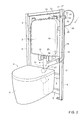
figure 1 is a diagrammatic rear view of a sanitary appliance having a flushing tank, in particular a sanitary appliance mounted on a concealed installation structure, and provided with an odor extraction system according to the present invention; -
figure 2 is a diagrammatic perspective view, with parts in transparency and parts removed for clarity, of the sanitary appliance infigure 1 with the odor extraction system of the invention. - In the accompanying figures,
reference numeral 1 indicates as a whole an odor extraction system installed on asanitary appliance 2 having aflushing tank 3, in particular a sanitary appliance mounted on aconcealed installation structure 4. - The
sanitary appliance 2, as well as theflushing tank 3 and thestructure 4 are of known type and are not thus described in detail for simplicity. - In the non-limiting example shown, the
sanitary appliance 2 is a toilet or urinal having asanitary bowl 5 connected to theflushing tank 3 by means of adrain tube 6. -
Bowl 5 andflushing tank 3 are supported by a supportingframe 7 of theinstallation structure 4. - The supporting
frame 7 has a pair ofuprights 8, which are vertical in use, and crossbars 9 arranged between theuprights 8. - The
flushing tank 3 internally houses a discharge valve and a feeding device (both known and not shown). - The
flushing tank 3 has alower outlet 10 formed in abottom wall 11 of theflushing tank 3 and connected to thedrain tube 6, and aservice opening 12 formed in a side orupper wall 13 of theflushing tank 3. -
System 1 comprises apowered fan 14, driven for example by anelectric motor 15 and having asuction inlet 16 and adelivery outlet 17; asuction pipe 18, connected to thesuction inlet 16 offan 14; and adelivery pipe 19 connected to thedelivery outlet 17 offan 14. -
Fan 14 and itsmotor 15 are, for example, housed in acasing 20 which is fixed in use to the supportingframe 7, for example to anupright 8, or to theflushing tank 3; thesuction pipe 18 and thedelivery pipe 19 extend fromfan 14 thus protruding fromcasing 20. - The
suction pipe 18 joins with thedrain tube 6 and is connected to thedrain tube 6 by means of abranch 21 placed on thedrain tube 6 between theflushing tank 3 and thebowl 5;branch 21 communicates with thedrain tube 6 through anauxiliary opening 22 formed in an side wall of thedrain tube 6. - The
suction pipe 18 connects thesuction pipe 16 offan 14 to theauxiliary opening 22 of thedrain tube 6. - The
delivery pipe 19 enters into theflushing tank 3, e.g. throughopening 12. - The
delivery pipe 19 extends from thedelivery opening 17 of the fan and ends with afree end 23 placed (in use) inside theflushing tank 3 and having anair outlet 24. - The
delivery pipe 19 has a length such thatend 23 with theair outlet 24 is, in use, in proximity of thebottom wall 11 and immersed in the water contained in theflushing tank 3, at least when theflushing tank 3 is full. -
End 23 is preferably provided with adiffuser 25, shaped so as to diffuse and/or disperse the air exiting from theair outlet 24 in the water in which end 23 is immersed. - In particular,
diffuser 25 has a plurality of emission nozzles or pores distributed around an axis ofdiffuser 25 and in which the air flow circulating in thedelivery pipe 19 is divided. - For example,
diffuser 25 comprises a porous piece through which the air exiting fromend 23 passes. - Furthermore,
system 1 comprises arecirculation conduit 26 which conveys the cooling air ofmotor 15 from the inside of casing 20 to thesuction pipe 18. - In particular, casing 20 has a
cooling outlet 27, formed through a wall ofcasing 20 and facingmotor 15; therecirculation conduit 26 connects thecooling outlet 27 to anauxiliary inlet 28 of thesuction pipe 18. - The
auxiliary inlet 28 is formed through a side wall of thesuction pipe 18. -
System 1 may be automatically operated by a specific control device (known and not shown) which turns onfan 14 when necessary. - In use, when
system 1 starts working, fan 14 aspirates air frombowl 5 through thesuction pipe 18 and thus extracts the odors frombowl 5. - The air flows through the
suction pipe 18 and thedelivery pipe 19 and exits fromend 23 throughdiffuser 25, which is immersed in the water contained in theflushing tank 3. The air is dispersed in the water which acts as a filter and prevents the odors from exiting into the environment. - The
recirculation conduit 26 takes fromcasing 20 the hot air which has cooledmotor 15, and discharges it into thesuction pipe 18, thus preventing this air and the odors carried by the same from being dispersed into the environment. - The air which cools
motor 15 is, for example, a fraction of the air which circulates insystem 1 by means offan 14; the air flow moved byfan 14 crosses thesuction pipe 18 and enters intocasing 20 where, at least in part, it is used to coolmotor 15. - The air flow circulating in
system 1 is thus divided into a first portion which crosses thedelivery pipe 19 and is dispersed in the water contained in theflushing tank 3, and in a second portion which is recirculated, through therecirculation conduit 26, to thesuction pipe 18. - Finally, it is understood that further changes and variations can be made to the odor extraction system described and shown herein, without departing from the scope of the appended claims.
Claims (8)
- An odor extraction system (1) for a sanitary appliance having a flushing tank (3), the system (1) comprising a powered fan (14) having a suction inlet (16) and a delivery outlet (17); a suction pipe (18), connected to the suction inlet (16) of the fan (14); and a delivery pipe (19) connected to the delivery outlet (17) of the fan (14); the system (1) being characterized in that the delivery pipe (19) is shaped so at to be inserted, in use, into the flushing tank (3) with a free end (23), provided with an air outlet (24), immersed in the water contained in the flushing tank (3).
- A system according to claim 1, wherein the delivery pipe (19) has a length such that the free end (23) is located, in use, in proximity of a bottom wall (11) of the flushing tank (3) and immersed in the water contained in the flushing tank (3), at least when the flushing tank (3) is filled with water.
- A system according to claim 1 or 2, wherein the free end (23) is provided with a diffuser (25), shaped so as to diffuse and/or disperse air exiting from the air outlet (24) in the water in which the free end (23) is immersed.
- A system according to claim 3, wherein the diffuser (25) has a plurality of emission nozzles or pores distributed around an axis of the diffuser (25) and in which the air flow circulating in the delivery pipe (19) is divided.
- A system according to claim 3 or 4, wherein the diffuser (25) comprises a porous piece located at the air outlet (24).
- A system according to one of the preceding claims, wherein the suction pipe (18) is connectable to a drain tube (6) which connects the flushing tank (3) to a sanitary bowl (5) of a sanitary appliance (2).
- A system according to one of the preceding claims, wherein the fan (14) is driven by a motor (15), and the fan (14) and the motor (15) are housed in a casing (20) having a cooling outlet (27) facing the motor (15); the system (1) comprising a recirculation conduit (26) which connects the cooling outlet (27) of the casing (20) with an auxiliary inlet (28) of the suction pipe (18), so as to recirculate cooling air of the motor (15) from the inside of the casing (20) to the suction pipe (18).
- A flushing tank (3) of a sanitary appliance (2), having a drain tube (6) connectable to a sanitary bowl (5) of the sanitary appliance (2) and characterized by comprising an odor extraction system (1) according to one of the preceding claims.
Applications Claiming Priority (1)
| Application Number | Priority Date | Filing Date | Title |
|---|---|---|---|
| ITMI20140920 | 2014-05-20 |
Publications (3)
| Publication Number | Publication Date |
|---|---|
| EP2947214A2 true EP2947214A2 (en) | 2015-11-25 |
| EP2947214A3 EP2947214A3 (en) | 2016-01-06 |
| EP2947214B1 EP2947214B1 (en) | 2017-11-22 |
Family
ID=51230016
Family Applications (1)
| Application Number | Title | Priority Date | Filing Date |
|---|---|---|---|
| EP15398005.7A Not-in-force EP2947214B1 (en) | 2014-05-20 | 2015-05-20 | Odor extraction system for a sanitary appliance having a flushing tank, and flushing tank comprising such an odor extraction system |
Country Status (2)
| Country | Link |
|---|---|
| EP (1) | EP2947214B1 (en) |
| RU (1) | RU2015118893A (en) |
Cited By (1)
| Publication number | Priority date | Publication date | Assignee | Title |
|---|---|---|---|---|
| CN106337482A (en) * | 2016-08-31 | 2017-01-18 | 孙鉴国 | Exhausting closestool |
Family Cites Families (4)
| Publication number | Priority date | Publication date | Assignee | Title |
|---|---|---|---|---|
| US5813060A (en) * | 1996-09-12 | 1998-09-29 | Klopocinski; Stanislaw | Multifunction toilet |
| GB2334042A (en) * | 1998-02-05 | 1999-08-11 | John Ernest Frederick Corfield | Ventilated water closet |
| GB2379462A (en) * | 2001-09-06 | 2003-03-12 | John Kennedy Fletcher | Toilet bowl odour remover |
| US20060107449A1 (en) * | 2004-11-23 | 2006-05-25 | Chih-Ming Lan | Fast environmentally benign toilet deodorizer |
-
2015
- 2015-05-19 RU RU2015118893A patent/RU2015118893A/en not_active Application Discontinuation
- 2015-05-20 EP EP15398005.7A patent/EP2947214B1/en not_active Not-in-force
Non-Patent Citations (1)
| Title |
|---|
| None |
Cited By (2)
| Publication number | Priority date | Publication date | Assignee | Title |
|---|---|---|---|---|
| CN106337482A (en) * | 2016-08-31 | 2017-01-18 | 孙鉴国 | Exhausting closestool |
| CN106337482B (en) * | 2016-08-31 | 2019-06-11 | 孙鉴国 | A kind of air suction type closestool |
Also Published As
| Publication number | Publication date |
|---|---|
| RU2015118893A (en) | 2016-12-10 |
| EP2947214A3 (en) | 2016-01-06 |
| RU2015118893A3 (en) | 2018-10-22 |
| EP2947214B1 (en) | 2017-11-22 |
Similar Documents
| Publication | Publication Date | Title |
|---|---|---|
| US9399862B2 (en) | Odor extractor | |
| EP2962612A1 (en) | Shower device with water recirculation and base section for such a shower device | |
| US20160040415A1 (en) | Ventilating System For Toilet Stool | |
| US10035150B2 (en) | System for supplying additive fluids within a waste disposal water supply system | |
| WO2013169415A1 (en) | Odor extractor | |
| US9696728B2 (en) | Secondary water supply system for a waste disposal | |
| US20130086736A1 (en) | Toilet ventilation device | |
| EP2947214B1 (en) | Odor extraction system for a sanitary appliance having a flushing tank, and flushing tank comprising such an odor extraction system | |
| KR101916890B1 (en) | Closestool having deodorization function | |
| CN204645202U (en) | Intelligence diodour antiplash toilet | |
| US20140338111A1 (en) | Odor Eliminating System for a Toilet | |
| US20090158515A1 (en) | Odor removal and air freshener system | |
| US9328496B2 (en) | System for the elimination of odours for a flushing sanitary apparatus | |
| CN104963399A (en) | Zero-pollution toilet | |
| EP2074266A2 (en) | Toilet bowl and toilet comprising such a bowl with odour extraction apparatus | |
| CN104963402A (en) | Zero-pollution urinal | |
| ES2288257T3 (en) | SPECIFIC EXTRACTOR EQUIPMENT FOR BATHROOMS. | |
| CN106836418B (en) | Toilet deodorization device and toilet deodorization system with same | |
| KR102294814B1 (en) | Deodorant device for toilet and deodorant seat for toilet with this | |
| CN109381094A (en) | A kind of dry pail latrine deodorization apparatus | |
| US20160122985A1 (en) | Air gap switch for a waste disposal water supply system | |
| PT104005A (en) | MULTI FUNCTION COLLECTOR FOR GRAY WATERS | |
| WO2021045694A1 (en) | Local waste air suction device | |
| GB2321654A (en) | Toilet bowl ventilator | |
| DE10326340A1 (en) | Wall-mounted toilet bowl has air extraction openings, over the highest water level and the flushing pipe inlet, to carry air into a chamber for extraction by a fan to remove odors |
Legal Events
| Date | Code | Title | Description |
|---|---|---|---|
| PUAI | Public reference made under article 153(3) epc to a published international application that has entered the european phase |
Free format text: ORIGINAL CODE: 0009012 |
|
| AK | Designated contracting states |
Kind code of ref document: A2 Designated state(s): AL AT BE BG CH CY CZ DE DK EE ES FI FR GB GR HR HU IE IS IT LI LT LU LV MC MK MT NL NO PL PT RO RS SE SI SK SM TR |
|
| AX | Request for extension of the european patent |
Extension state: BA ME |
|
| PUAL | Search report despatched |
Free format text: ORIGINAL CODE: 0009013 |
|
| AK | Designated contracting states |
Kind code of ref document: A3 Designated state(s): AL AT BE BG CH CY CZ DE DK EE ES FI FR GB GR HR HU IE IS IT LI LT LU LV MC MK MT NL NO PL PT RO RS SE SI SK SM TR |
|
| AX | Request for extension of the european patent |
Extension state: BA ME |
|
| RIC1 | Information provided on ipc code assigned before grant |
Ipc: E03D 9/052 20060101AFI20151202BHEP Ipc: E03D 9/05 20060101ALI20151202BHEP |
|
| 17P | Request for examination filed |
Effective date: 20160706 |
|
| RBV | Designated contracting states (corrected) |
Designated state(s): AL AT BE BG CH CY CZ DE DK EE ES FI FR GB GR HR HU IE IS IT LI LT LU LV MC MK MT NL NO PL PT RO RS SE SI SK SM TR |
|
| GRAP | Despatch of communication of intention to grant a patent |
Free format text: ORIGINAL CODE: EPIDOSNIGR1 |
|
| INTG | Intention to grant announced |
Effective date: 20170613 |
|
| RAP1 | Party data changed (applicant data changed or rights of an application transferred) |
Owner name: OLI - SISTEMAS SANITARIOS, S.A. |
|
| GRAS | Grant fee paid |
Free format text: ORIGINAL CODE: EPIDOSNIGR3 |
|
| GRAA | (expected) grant |
Free format text: ORIGINAL CODE: 0009210 |
|
| AK | Designated contracting states |
Kind code of ref document: B1 Designated state(s): AL AT BE BG CH CY CZ DE DK EE ES FI FR GB GR HR HU IE IS IT LI LT LU LV MC MK MT NL NO PL PT RO RS SE SI SK SM TR |
|
| REG | Reference to a national code |
Ref country code: GB Ref legal event code: FG4D |
|
| REG | Reference to a national code |
Ref country code: CH Ref legal event code: EP |
|
| REG | Reference to a national code |
Ref country code: IE Ref legal event code: FG4D |
|
| REG | Reference to a national code |
Ref country code: AT Ref legal event code: REF Ref document number: 948539 Country of ref document: AT Kind code of ref document: T Effective date: 20171215 |
|
| REG | Reference to a national code |
Ref country code: DE Ref legal event code: R096 Ref document number: 602015006184 Country of ref document: DE |
|
| REG | Reference to a national code |
Ref country code: NL Ref legal event code: MP Effective date: 20171122 |
|
| REG | Reference to a national code |
Ref country code: LT Ref legal event code: MG4D |
|
| REG | Reference to a national code |
Ref country code: AT Ref legal event code: MK05 Ref document number: 948539 Country of ref document: AT Kind code of ref document: T Effective date: 20171122 |
|
| PG25 | Lapsed in a contracting state [announced via postgrant information from national office to epo] |
Ref country code: ES Free format text: LAPSE BECAUSE OF FAILURE TO SUBMIT A TRANSLATION OF THE DESCRIPTION OR TO PAY THE FEE WITHIN THE PRESCRIBED TIME-LIMIT Effective date: 20171122 Ref country code: SE Free format text: LAPSE BECAUSE OF FAILURE TO SUBMIT A TRANSLATION OF THE DESCRIPTION OR TO PAY THE FEE WITHIN THE PRESCRIBED TIME-LIMIT Effective date: 20171122 Ref country code: NO Free format text: LAPSE BECAUSE OF FAILURE TO SUBMIT A TRANSLATION OF THE DESCRIPTION OR TO PAY THE FEE WITHIN THE PRESCRIBED TIME-LIMIT Effective date: 20180222 Ref country code: NL Free format text: LAPSE BECAUSE OF FAILURE TO SUBMIT A TRANSLATION OF THE DESCRIPTION OR TO PAY THE FEE WITHIN THE PRESCRIBED TIME-LIMIT Effective date: 20171122 Ref country code: LT Free format text: LAPSE BECAUSE OF FAILURE TO SUBMIT A TRANSLATION OF THE DESCRIPTION OR TO PAY THE FEE WITHIN THE PRESCRIBED TIME-LIMIT Effective date: 20171122 Ref country code: FI Free format text: LAPSE BECAUSE OF FAILURE TO SUBMIT A TRANSLATION OF THE DESCRIPTION OR TO PAY THE FEE WITHIN THE PRESCRIBED TIME-LIMIT Effective date: 20171122 |
|
| PG25 | Lapsed in a contracting state [announced via postgrant information from national office to epo] |
Ref country code: LV Free format text: LAPSE BECAUSE OF FAILURE TO SUBMIT A TRANSLATION OF THE DESCRIPTION OR TO PAY THE FEE WITHIN THE PRESCRIBED TIME-LIMIT Effective date: 20171122 Ref country code: GR Free format text: LAPSE BECAUSE OF FAILURE TO SUBMIT A TRANSLATION OF THE DESCRIPTION OR TO PAY THE FEE WITHIN THE PRESCRIBED TIME-LIMIT Effective date: 20180223 Ref country code: AT Free format text: LAPSE BECAUSE OF FAILURE TO SUBMIT A TRANSLATION OF THE DESCRIPTION OR TO PAY THE FEE WITHIN THE PRESCRIBED TIME-LIMIT Effective date: 20171122 Ref country code: BG Free format text: LAPSE BECAUSE OF FAILURE TO SUBMIT A TRANSLATION OF THE DESCRIPTION OR TO PAY THE FEE WITHIN THE PRESCRIBED TIME-LIMIT Effective date: 20180222 Ref country code: HR Free format text: LAPSE BECAUSE OF FAILURE TO SUBMIT A TRANSLATION OF THE DESCRIPTION OR TO PAY THE FEE WITHIN THE PRESCRIBED TIME-LIMIT Effective date: 20171122 Ref country code: RS Free format text: LAPSE BECAUSE OF FAILURE TO SUBMIT A TRANSLATION OF THE DESCRIPTION OR TO PAY THE FEE WITHIN THE PRESCRIBED TIME-LIMIT Effective date: 20171122 |
|
| PG25 | Lapsed in a contracting state [announced via postgrant information from national office to epo] |
Ref country code: DK Free format text: LAPSE BECAUSE OF FAILURE TO SUBMIT A TRANSLATION OF THE DESCRIPTION OR TO PAY THE FEE WITHIN THE PRESCRIBED TIME-LIMIT Effective date: 20171122 Ref country code: CY Free format text: LAPSE BECAUSE OF FAILURE TO SUBMIT A TRANSLATION OF THE DESCRIPTION OR TO PAY THE FEE WITHIN THE PRESCRIBED TIME-LIMIT Effective date: 20171122 Ref country code: EE Free format text: LAPSE BECAUSE OF FAILURE TO SUBMIT A TRANSLATION OF THE DESCRIPTION OR TO PAY THE FEE WITHIN THE PRESCRIBED TIME-LIMIT Effective date: 20171122 Ref country code: CZ Free format text: LAPSE BECAUSE OF FAILURE TO SUBMIT A TRANSLATION OF THE DESCRIPTION OR TO PAY THE FEE WITHIN THE PRESCRIBED TIME-LIMIT Effective date: 20171122 Ref country code: SK Free format text: LAPSE BECAUSE OF FAILURE TO SUBMIT A TRANSLATION OF THE DESCRIPTION OR TO PAY THE FEE WITHIN THE PRESCRIBED TIME-LIMIT Effective date: 20171122 |
|
| REG | Reference to a national code |
Ref country code: DE Ref legal event code: R097 Ref document number: 602015006184 Country of ref document: DE |
|
| PG25 | Lapsed in a contracting state [announced via postgrant information from national office to epo] |
Ref country code: SM Free format text: LAPSE BECAUSE OF FAILURE TO SUBMIT A TRANSLATION OF THE DESCRIPTION OR TO PAY THE FEE WITHIN THE PRESCRIBED TIME-LIMIT Effective date: 20171122 Ref country code: RO Free format text: LAPSE BECAUSE OF FAILURE TO SUBMIT A TRANSLATION OF THE DESCRIPTION OR TO PAY THE FEE WITHIN THE PRESCRIBED TIME-LIMIT Effective date: 20171122 Ref country code: IT Free format text: LAPSE BECAUSE OF FAILURE TO SUBMIT A TRANSLATION OF THE DESCRIPTION OR TO PAY THE FEE WITHIN THE PRESCRIBED TIME-LIMIT Effective date: 20171122 Ref country code: PL Free format text: LAPSE BECAUSE OF FAILURE TO SUBMIT A TRANSLATION OF THE DESCRIPTION OR TO PAY THE FEE WITHIN THE PRESCRIBED TIME-LIMIT Effective date: 20171122 |
|
| PLBE | No opposition filed within time limit |
Free format text: ORIGINAL CODE: 0009261 |
|
| STAA | Information on the status of an ep patent application or granted ep patent |
Free format text: STATUS: NO OPPOSITION FILED WITHIN TIME LIMIT |
|
| 26N | No opposition filed |
Effective date: 20180823 |
|
| PG25 | Lapsed in a contracting state [announced via postgrant information from national office to epo] |
Ref country code: SI Free format text: LAPSE BECAUSE OF FAILURE TO SUBMIT A TRANSLATION OF THE DESCRIPTION OR TO PAY THE FEE WITHIN THE PRESCRIBED TIME-LIMIT Effective date: 20171122 |
|
| REG | Reference to a national code |
Ref country code: CH Ref legal event code: PL |
|
| REG | Reference to a national code |
Ref country code: BE Ref legal event code: MM Effective date: 20180531 |
|
| PG25 | Lapsed in a contracting state [announced via postgrant information from national office to epo] |
Ref country code: MC Free format text: LAPSE BECAUSE OF FAILURE TO SUBMIT A TRANSLATION OF THE DESCRIPTION OR TO PAY THE FEE WITHIN THE PRESCRIBED TIME-LIMIT Effective date: 20171122 |
|
| REG | Reference to a national code |
Ref country code: IE Ref legal event code: MM4A |
|
| PG25 | Lapsed in a contracting state [announced via postgrant information from national office to epo] |
Ref country code: CH Free format text: LAPSE BECAUSE OF NON-PAYMENT OF DUE FEES Effective date: 20180531 Ref country code: LI Free format text: LAPSE BECAUSE OF NON-PAYMENT OF DUE FEES Effective date: 20180531 |
|
| PG25 | Lapsed in a contracting state [announced via postgrant information from national office to epo] |
Ref country code: LU Free format text: LAPSE BECAUSE OF NON-PAYMENT OF DUE FEES Effective date: 20180520 |
|
| PG25 | Lapsed in a contracting state [announced via postgrant information from national office to epo] |
Ref country code: FR Free format text: LAPSE BECAUSE OF NON-PAYMENT OF DUE FEES Effective date: 20180531 Ref country code: IE Free format text: LAPSE BECAUSE OF NON-PAYMENT OF DUE FEES Effective date: 20180520 |
|
| PG25 | Lapsed in a contracting state [announced via postgrant information from national office to epo] |
Ref country code: BE Free format text: LAPSE BECAUSE OF NON-PAYMENT OF DUE FEES Effective date: 20180531 |
|
| GBPC | Gb: european patent ceased through non-payment of renewal fee |
Effective date: 20190520 |
|
| PG25 | Lapsed in a contracting state [announced via postgrant information from national office to epo] |
Ref country code: MT Free format text: LAPSE BECAUSE OF NON-PAYMENT OF DUE FEES Effective date: 20180520 |
|
| PG25 | Lapsed in a contracting state [announced via postgrant information from national office to epo] |
Ref country code: TR Free format text: LAPSE BECAUSE OF FAILURE TO SUBMIT A TRANSLATION OF THE DESCRIPTION OR TO PAY THE FEE WITHIN THE PRESCRIBED TIME-LIMIT Effective date: 20171122 |
|
| PG25 | Lapsed in a contracting state [announced via postgrant information from national office to epo] |
Ref country code: GB Free format text: LAPSE BECAUSE OF NON-PAYMENT OF DUE FEES Effective date: 20190520 |
|
| PG25 | Lapsed in a contracting state [announced via postgrant information from national office to epo] |
Ref country code: PT Free format text: LAPSE BECAUSE OF FAILURE TO SUBMIT A TRANSLATION OF THE DESCRIPTION OR TO PAY THE FEE WITHIN THE PRESCRIBED TIME-LIMIT Effective date: 20171122 |
|
| PG25 | Lapsed in a contracting state [announced via postgrant information from national office to epo] |
Ref country code: HU Free format text: LAPSE BECAUSE OF FAILURE TO SUBMIT A TRANSLATION OF THE DESCRIPTION OR TO PAY THE FEE WITHIN THE PRESCRIBED TIME-LIMIT; INVALID AB INITIO Effective date: 20150520 Ref country code: MK Free format text: LAPSE BECAUSE OF NON-PAYMENT OF DUE FEES Effective date: 20171122 |
|
| PG25 | Lapsed in a contracting state [announced via postgrant information from national office to epo] |
Ref country code: AL Free format text: LAPSE BECAUSE OF FAILURE TO SUBMIT A TRANSLATION OF THE DESCRIPTION OR TO PAY THE FEE WITHIN THE PRESCRIBED TIME-LIMIT Effective date: 20171122 Ref country code: IS Free format text: LAPSE BECAUSE OF FAILURE TO SUBMIT A TRANSLATION OF THE DESCRIPTION OR TO PAY THE FEE WITHIN THE PRESCRIBED TIME-LIMIT Effective date: 20180322 |
|
| PGFP | Annual fee paid to national office [announced via postgrant information from national office to epo] |
Ref country code: DE Payment date: 20220527 Year of fee payment: 8 |
|
| REG | Reference to a national code |
Ref country code: DE Ref legal event code: R119 Ref document number: 602015006184 Country of ref document: DE |
|
| PG25 | Lapsed in a contracting state [announced via postgrant information from national office to epo] |
Ref country code: DE Free format text: LAPSE BECAUSE OF NON-PAYMENT OF DUE FEES Effective date: 20231201 |