EP2947209B1 - Verbesserte aufzugsanordnung für ein arbeitsfahrzeug - Google Patents
Verbesserte aufzugsanordnung für ein arbeitsfahrzeug Download PDFInfo
- Publication number
- EP2947209B1 EP2947209B1 EP15164900.1A EP15164900A EP2947209B1 EP 2947209 B1 EP2947209 B1 EP 2947209B1 EP 15164900 A EP15164900 A EP 15164900A EP 2947209 B1 EP2947209 B1 EP 2947209B1
- Authority
- EP
- European Patent Office
- Prior art keywords
- control
- pivot point
- lift
- coupled
- cylinder
- Prior art date
- Legal status (The legal status is an assumption and is not a legal conclusion. Google has not performed a legal analysis and makes no representation as to the accuracy of the status listed.)
- Active
Links
Images


Classifications
-
- E—FIXED CONSTRUCTIONS
- E02—HYDRAULIC ENGINEERING; FOUNDATIONS; SOIL SHIFTING
- E02F—DREDGING; SOIL-SHIFTING
- E02F3/00—Dredgers; Soil-shifting machines
- E02F3/04—Dredgers; Soil-shifting machines mechanically-driven
- E02F3/28—Dredgers; Soil-shifting machines mechanically-driven with digging tools mounted on a dipper- or bucket-arm, i.e. there is either one arm or a pair of arms, e.g. dippers, buckets
- E02F3/36—Component parts
- E02F3/42—Drives for dippers, buckets, dipper-arms or bucket-arms
- E02F3/43—Control of dipper or bucket position; Control of sequence of drive operations
- E02F3/431—Control of dipper or bucket position; Control of sequence of drive operations for bucket-arms, front-end loaders, dumpers or the like
-
- E—FIXED CONSTRUCTIONS
- E02—HYDRAULIC ENGINEERING; FOUNDATIONS; SOIL SHIFTING
- E02F—DREDGING; SOIL-SHIFTING
- E02F3/00—Dredgers; Soil-shifting machines
- E02F3/04—Dredgers; Soil-shifting machines mechanically-driven
- E02F3/28—Dredgers; Soil-shifting machines mechanically-driven with digging tools mounted on a dipper- or bucket-arm, i.e. there is either one arm or a pair of arms, e.g. dippers, buckets
- E02F3/34—Dredgers; Soil-shifting machines mechanically-driven with digging tools mounted on a dipper- or bucket-arm, i.e. there is either one arm or a pair of arms, e.g. dippers, buckets with bucket-arms, i.e. a pair of arms, e.g. manufacturing processes, form, geometry, material of bucket-arms directly pivoted on the frames of tractors or self-propelled machines
- E02F3/3405—Dredgers; Soil-shifting machines mechanically-driven with digging tools mounted on a dipper- or bucket-arm, i.e. there is either one arm or a pair of arms, e.g. dippers, buckets with bucket-arms, i.e. a pair of arms, e.g. manufacturing processes, form, geometry, material of bucket-arms directly pivoted on the frames of tractors or self-propelled machines and comprising an additional linkage mechanism
-
- E—FIXED CONSTRUCTIONS
- E02—HYDRAULIC ENGINEERING; FOUNDATIONS; SOIL SHIFTING
- E02F—DREDGING; SOIL-SHIFTING
- E02F3/00—Dredgers; Soil-shifting machines
- E02F3/04—Dredgers; Soil-shifting machines mechanically-driven
- E02F3/28—Dredgers; Soil-shifting machines mechanically-driven with digging tools mounted on a dipper- or bucket-arm, i.e. there is either one arm or a pair of arms, e.g. dippers, buckets
- E02F3/34—Dredgers; Soil-shifting machines mechanically-driven with digging tools mounted on a dipper- or bucket-arm, i.e. there is either one arm or a pair of arms, e.g. dippers, buckets with bucket-arms, i.e. a pair of arms, e.g. manufacturing processes, form, geometry, material of bucket-arms directly pivoted on the frames of tractors or self-propelled machines
- E02F3/3414—Dredgers; Soil-shifting machines mechanically-driven with digging tools mounted on a dipper- or bucket-arm, i.e. there is either one arm or a pair of arms, e.g. dippers, buckets with bucket-arms, i.e. a pair of arms, e.g. manufacturing processes, form, geometry, material of bucket-arms directly pivoted on the frames of tractors or self-propelled machines the arms being pivoted at the rear of the vehicle chassis, e.g. skid steer loader
-
- E—FIXED CONSTRUCTIONS
- E02—HYDRAULIC ENGINEERING; FOUNDATIONS; SOIL SHIFTING
- E02F—DREDGING; SOIL-SHIFTING
- E02F3/00—Dredgers; Soil-shifting machines
- E02F3/04—Dredgers; Soil-shifting machines mechanically-driven
- E02F3/28—Dredgers; Soil-shifting machines mechanically-driven with digging tools mounted on a dipper- or bucket-arm, i.e. there is either one arm or a pair of arms, e.g. dippers, buckets
- E02F3/36—Component parts
- E02F3/42—Drives for dippers, buckets, dipper-arms or bucket-arms
- E02F3/422—Drive systems for bucket-arms, front-end loaders, dumpers or the like
-
- E—FIXED CONSTRUCTIONS
- E02—HYDRAULIC ENGINEERING; FOUNDATIONS; SOIL SHIFTING
- E02F—DREDGING; SOIL-SHIFTING
- E02F9/00—Component parts of dredgers or soil-shifting machines, not restricted to one of the kinds covered by groups E02F3/00 - E02F7/00
- E02F9/26—Indicating devices
- E02F9/264—Sensors and their calibration for indicating the position of the work tool
Definitions
- the present subject matter relates generally to work vehicles and, more particularly, to an improved lift assembly that allows for the loader arms of a work vehicle to be raised and/or lowered along a plurality of different travel paths.
- skid steer loaders typically include a pair of loader arms pivotally coupled to the vehicle's chassis that can be raised and lowered at the operator's command.
- the loader arms typically have an implement attached to their end, thereby allowing the implement to be moved relative to the ground as the loader arms are raised and lowered.
- a bucket is often coupled to the loader arm, which allows the skid steer loader to be used to carry supplies or particulate matter, such as gravel, sand, or dirt, around a worksite.
- each lift arm is coupled to the loader chassis at a given pivot point and is configured to be raised and lowered by a corresponding lift cylinder.
- the loader arms may be raised and lowered, respectively, along a radial or arced path centered at the pivot point defined between the loader arms and the chassis.
- Such a radial lift path is often adequate for many loader applications but may not be the most desirable in applications where there is a need to alter the lift path of the loader arms to optimize performance for various tasks. For instance, to increase the rated operating capacity of the loader, it is desirable to have a substantially vertical lift path for the loader arms.
- US2006/243234 A1 discloses a lift assembly having a loader arm and a control arm, whereby a lift cylinder is coupled between the loader arm and the chassis and a control cylinder connected to the chassis and a counter arm.
- an improved lift assembly for a work vehicle that allows for the loader arms of such vehicle to be raised and/or lowered along a plurality of different travel paths to allow for variations in the rated operating capacity, horizontal reach and/or cycle times associated with the loader arms would be welcomed in the technology.
- the present subject matter is directed to a lift assembly for a work vehicle.
- the lift assembly may generally include a loader arm extending between a forward end and a rear end and a control arm extending between a first end and a second end.
- the first end may be coupled to a chassis of the work vehicle at a first pivot point and the second end may be coupled to the rear end of the loader arm at a second pivot point.
- the lift assembly may include a lift cylinder coupled between the loader arm and the chassis and a control cylinder extending between an upper end and a lower end, with the upper end being coupled to the control arm and the lower end being coupled to the chassis at a third pivot point.
- the first pivot point may be located rearward of the second pivot point when the control cylinder is at a fully retracted position.
- the present subject matter is directed to a lift assembly for a work vehicle.
- the lift assembly may generally include a loader arm extending between a forward end and a rear end and a control arm extending between a first end and a second end. The first end may be coupled to a chassis of the work vehicle at a first pivot point and the second end may be coupled to the rear end of the loader arm at a second pivot point.
- the lift assembly may include a lift cylinder coupled between the loader arm and the chassis and a control cylinder extending between an upper end and a lower end, with the upper end being coupled to the control arm and the lower end being coupled to the chassis at a third pivot point.
- the lift cylinder may be coupled to the chassis at a fourth pivot point that is positioned both vertically below and rearward of the third pivot point.
- the present subject matter is directed to a method for controlling a lift assembly of a work vehicle.
- the lift assembly may include a loader arm and a control arm, wherein the control arm extends between a first end coupled to a chassis of the work vehicle at a first pivot point and a second end coupled to the loader arm at a second pivot point.
- the method may generally include receiving an operator input associated with a selection of a desired travel path for the loader arm, receiving at least one sensor measurement associated with a position of at least one of the loader arm or the control arm and controlling an actuation of at least one of a lift cylinder or a control cylinder of the lift assembly based on the at least one senor measurement such that a reference point defined on the loader arm is raised or lowered along the desired travel path, wherein the lift cylinder is coupled between the loader arm and the chassis and wherein the control cylinder extends between an upper end coupled to the control arm and a lower end coupled to the chassis at a third pivot point.
- the present subject matter is directed to an improved lift assembly for a work vehicle.
- the lift assembly may include a pair of loader arms pivotally coupled to a corresponding pair of control arms, with each control arm being pivotally coupled, in turn, to the chassis of the work vehicle.
- the lift assembly may include a pair of lift cylinders for raising and lowering the loader arms and a pair of control cylinders for adjusting the position of a dynamic pivot point defined between the control arms and the loader arms.
- the control arms may be pivoted about a fixed pivot point defined between the control arms and the chassis, thereby adjusting the relative position of the dynamic pivot point.
- Such adjustments of the dynamic pivot point may allow for the travel path of the loader arms to be varied as the arms are raised and/or lowered relative to the ground via the lift cylinders.
- the loader arms may be raised and/or lowered along a plurality of different travel paths, thereby allowing specific travel paths to be selected and/or tailored to the requirements of the work being performed.
- the actuation of the control cylinders and the lift cylinders may be controlled in a manner that provides for the forward end of the loader arms (i.e., the end coupled to a suitable implement, such as a bucket) to be raised and/or lowered along a substantially vertical travel path.
- control cylinders and lift cylinders may be controlled in a manner that provides for the forward end of the loader arms to be raised and/or lowered along a more radial or arcuate travel path.
- control cylinders may also allow for the forward end of the loader arms to be raised and/or lowered along an absolute straight vertical travel path along at least a portion of the vertical distance defined between the vehicle's driving surface and the maximum lift height for the loader arms.
- FIGS. 1-3 one embodiment of a work vehicle 10 is illustrated in accordance with aspects of the present subject matter.
- FIG. 1 illustrates a side view of the work vehicle 10, particularly illustrating an implement 12 of the work vehicle 10 being located at its lowermost position relative to a driving surface 22 of the vehicle 10.
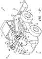
- FIG. 2 illustrates a rear perspective view of the work vehicle 10 shown in FIG. 1
- FIG. 3 illustrates a front perspective of the work vehicle 10 after the implement 12 has been raised from its lowermost position.
- the forward direction indicated by arrow 14 in FIG. 1
- the reverse direction indicated by arrow 16 in FIG. 1
- a first location on the work vehicle 10 may be considered to be positioned rearward of a second location on the work vehicle 10 if the first location is positioned closer to the rear end 20 of the work vehicle 10 than the second location along a reference plane extending parallel to the driving surface 22.
- the work vehicle 10 is configured as a skid steer loader.
- the work vehicle 10 may be configured as any other suitable work vehicle known in the art, such as any other work vehicle including loader arms (e.g., telescopic handlers, wheel loaders, backhoe loaders, forklifts, compact track loaders and/or the like).
- loader arms e.g., telescopic handlers, wheel loaders, backhoe loaders, forklifts, compact track loaders and/or the like.
- the work vehicle 10 includes a pair of front wheels 24, a pair of rear wheels 26 and a chassis 28 coupled to and supported by the wheels 24, 26.
- An operator's cab 30 may be supported by a portion of the chassis 28 and may house various input devices for permitting an operator to control the operation of the work vehicle 10.
- the work vehicle 10 may include an engine (not shown) and a hydrostatic drive unit (not shown) coupled to or otherwise supported by the chassis 28.
- a component may be "coupled to" the chassis 28 by being directly coupled to a component of the chassis 28 or by being indirectly coupled to a component of the chassis 28 (e.g., via a secondary component).
- the work vehicle 10 may also include a lift assembly 36 for raising and lowering the implement 12 (e.g., a bucket, fork, blade and/or the like) relative to the driving surface 22 of the vehicle 10.
- the lift assembly 36 may include a pair of loader arms (e.g., a first loader arm 38 and a second loader arm 40) pivotally coupled to the implement 12 and a corresponding pair of control arms (e.g., a first control arm 42 and a second control arm 44) pivotally coupled between the loader arms 38, 40 and the chassis 28.
- a pair of loader arms e.g., a first loader arm 38 and a second loader arm 40
- control arms e.g., a first control arm 42 and a second control arm 44
- the loader arms 38, 40 may each be configured to extend lengthwise between a forward end 46 and an aft end 48, with the forward end 46 of each loader arm 38, 40 being pivotally coupled to the implement 12 at a forward pivot point 50 and the aft end 48 of each loader arm 38, 40 being pivotally coupled to its corresponding control arm 42, 44 at a dynamic rear pivot point 52.
- each control arm 42, 44 may extend between a first end 54 and a second end 56, with the first end 54 being pivotally coupled to the chassis 28 at a fixed pivot point 58 and the second end 56 being pivotally coupled to the aft end 48 of the corresponding loader arm 38, 40 at the dynamic pivot point 52.
- a connector arm 60 may be configured to extend perpendicularly between the control arms 42, 44 in order to secure the control arms 42, 44 to one another.
- the connector arm 60 may have a tube-like configuration and may be configured to be inserted through corresponding openings (not shown) defined in the control arms 42, 44.
- the connector arm 60 may be secured within the openings (e.g., by welding the portions of the connector arm 60 extending through the openings to the control arms 44, 44) in order to form a frame assembly comprised of the control arms 42, 44 and the connector arm 60.
- the lift assembly 36 may also include a pair of hydraulic lift cylinders 62 coupled between the chassis 28 and the loader arms 38, 40 and a pair of hydraulic tilt cylinders 64 coupled between the loader arms 38, 40 and the implement 12.
- each lift cylinder 62 may be pivotally coupled to the chassis at a lift pivot point 66 and may extend outwardly therefrom so to be coupled to its corresponding loader arm 38, 40 at an intermediate attachment location 68 defined between the forward and aft ends 46, 48 of each loader arm 38, 40.
- each tilt cylinder 68 may be coupled to its corresponding loader arm 38, 40 at a first attachment location 70 and may extend outwardly therefrom so as to be coupled to the implement 12 at a second attachment location 72.
- lift and tilt cylinders 62, 64 may be utilized to allow the implement 12 to be raised/lowered and/or pivoted relative to the driving surface 22 of the work vehicle 10.
- the lift cylinders 62 may be extended and retracted in order to pivot the loader arms 38, 40 upward and downwards, respectively, about the dynamic pivot point 52, thereby at least partially controlling the vertical positioning of the implement 12 relative to the driving surface 22.
- the tilt cylinders 64 may be extended and retracted in order to pivot the implement 12 relative to the loader arms 38, 40 about the forward pivot point 50, thereby controlling the tilt angle or orientation of the implement 12 relative to the driving surface 22.
- the lift assembly 36 may also include a pair of control cylinders 74 for adjusting the relative location of the dynamic pivot point 52, thereby allowing for the travel path of the loader arms 38, 40 to be dynamically adjusted as the implement 12 is being raised and/or lowered relative to the drive surface 22.
- the control cylinders 74 may each be configured to extend between a top end 76 and a bottom end 78, with the top end 76 of each control cylinder 74 being pivotally coupled to its corresponding control arm 42, 44 at the dynamic pivot point 52 and the bottom end 78 being pivotally coupled to the vehicle's chassis 28 at a control pivot point 80.
- each control cylinder 74 may be coupled to the corresponding control arm 42, 44 at any other suitable location along the arm's length, such as at a location between the dynamic pivot point 52 and the fixed pivot point 58.
- the control cylinders 74 may be extended and retracted in order to adjust the location of the dynamic pivot point 52 in a counter-clockwise direction or a clockwise direction, respectively, about the fixed pivot point 58.
- the loader arms 38, 40 may be raised and/or lowered along any number of different travel paths as the lift cylinders 62 as are used to adjust the position of the implement12 relative to the driving surface 22.
- FIG. 1 illustrates a bounded travel area 82 defining the potential area across which the forward pivot point 50 may be moved using the disclosed lift assembly 36.
- the travel area 82 is defined by a first boundary line 83, a second boundary line 84, a third boundary line 85 and a fourth boundary line 86.
- the first and third boundary lines 83, 85 generally define the range of movement for the loader arms 38, 40 at the forward pivot point 50 when the control cylinders 74 are being actuated while the lift cylinders 62 are maintained at either their fully retracted position or their fully extended position.
- the forward pivot point 50 when the forward pivot point 50 is located at the lowermost position within the bounded travel area 82 (i.e., at point 87), the forward pivot point 50 may be moved along the first boundary line 83 to point 88 by simply actuating the control cylinders 74 from a fully retracted position (at point 87) to a fully extended position (at point 88) while maintaining the lift cylinders 62 at their fully retracted position.
- the forward pivot point 50 may be moved along the third boundary line 85 from point 89 to point 90 by simply actuating the control cylinders 74 from a fully extended position (at point 89) to a fully retracted position (at point 90) while maintaining the lift cylinders 62 at their fully extended position.
- the second and fourth boundary lines 84, 86 generally define the range of movement for the loader arms 38, 40 at the forward pivot point 50 when the lift cylinders 62 are being actuated while the control cylinders 74 are maintained in either their fully extended position or their fully retracted position.
- the lift cylinders 62 may be actuated from a fully retracted position (at point 88) to a fully extended position (at point 89) while maintaining the control cylinders 74 at their fully extended position.
- the lift cylinders 62 may be actuated from a fully retracted position (at point 87) to a fully extended position (at point 90) while maintaining the control cylinders 74 at their fully retracted position.
- each control cylinder 74 may be either initially maintained at its fully retracted position (e.g., to raise the forward pivot point 50 along the fourth boundary line 86) or initially extended outwardly from its fully retracted position (e.g., to initially move the forward pivot point 50 to any location rearward of the fourth boundary line 86).
- the positioning of the control arms 42, 44 relative to the loader arms 38, 40 and/or the relative positioning of the various pivot points 52, 58, 66, 80 may be selected such that the desired travel area 82 is defined for the loader arms 38, 40 at the forward pivot point 50.
- the location of the fixed pivot point 58 may be selected such that the pivot point 58 is positioned rearward of and vertically below the dynamic pivot point 52 when the control cylinders 74 are at their fully retracted positions.
- each control arm 42, 44 may be configured to be angled both forward and upward from its first end 54 to its second end 56 when the control cylinders 74 are at their fully retracted positions.
- the location of the fixed pivot point 58 may be selected such that the pivot point 58 is still positioned rearward of the dynamic pivot point 52 even when the control cylinders 74 are at their fully extended positions.
- the location of the control pivot point 80 for each control cylinder 74 may be selected such that the pivot point 80 is located both vertically above and forward of the lift pivot point 66 for each lift cylinder 62.
- control arms 42, 44 may be adjusted to provide any other suitable configuration that allows for the loader arms 38, 40 to be raised and/or lowered along a plurality of different travel paths in a manner consistent with the disclosure provided herein.
- any number of different travel paths may be achieved within such area 82 by selectively actuating the lift cylinders 62 and the control cylinders 74 as the loader arms 38, 40 are being raised and/or lowered relative to the driving surface 22.
- the implement 12 may be raised to a given height 91 above the vehicle's driving surface 22 (e.g., such that the forward pivot point 50 is located at point 92).
- the loader arms 38, 40 may be directed along various different travel paths as the forward pivot point 50 is moved between point 87 and point 92. For example, as shown in FIG.
- a substantially vertical travel path 93 may be defined between the points 87 and 92, which may allow for the work vehicle 10 to have an increased lift capacity.
- a more radial or arced travel path 94 may be defined between the points 87 and 92, which may allow for the implement 12 to be raised to the desired height 91 in a shorter amount of time than that required for the substantially vertical travel path 93.
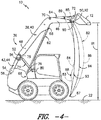
- FIG. 5 Another example of suitable travels paths that may be provided within the bounded travel area 82 is shown in FIG. 5 .
- the implement 12 may be raised to a certain vertical height 95 while also being capable of extending outwardly a given horizontal distance 96 in order to increase the overall reach of the implement 12 (e.g., to point 97).
- various different travel paths may be defined between point 87 and point 97.
- a substantially vertical travel path 98 may defined between the points 87 and 97, which may allow for increased lift capacity.
- a more radial or arced travel path 88 may be defined between points 87 and 97, which may allow for the loader arms 38, 40 to be raised and/or lowered in less time.
- the various travel paths 93, 94, 98, 99 shown in FIGS. 4 and 5 are simply illustrated to provide several examples of suitable travel paths that may be achieved using the disclosed lift assembly 36.
- any number of different travel paths may be defined within the bounded travel area 82 by altering the manner in which the control cylinders 74 and the lift cylinders 62 are actuated as the implement 12 is being raised and/or lowered relative to the driving surface 22.
- the bounded travel area 82 for the loader arms 38, 40 may be defined relative to any other suitable reference point or location along each loader arm 38, 40.
- the shape and/or size of bounded travel area 82 may be varied significantly.
- the bounded travel area 82 may be expanded or shifted rearward such that the forward pivot point 50 may be moved along an absolute straight vertical travel path from the lowermost position 87. An example of such a lift path is illustrated in FIG. 6 .
- control cylinders 74 and the lift cylinders 62 may be controlled in a manner that allows the forward pivot point to be raised and lowered along a vertically straight path 300 extending between point 87 and point 302.
- the lift cylinders 62 may, in one embodiment, by configured such that each cylinder 62 is not in its fully retracted position when the forward pivot point 50 is located at the lowermost position 87 (i.e., such that the lift cylinders 62 may be further retracted at point 87).
- Such a configuration may generally allow for the aft boundary of the bounded travel area (e.g., defined by the first and second boundary lines 83, 84 shown in FIGS.
- the lift cylinders 62 may be initially retracted towards their fully retracted position while the control cylinders 74 are extended until the forward pivot point 50 has reached a given height 304. Thereafter, the lift cylinders 62 may be extended as the control cylinders 74 are controlled in a manner that allows the forward pivot point 50 to be lifted along the remainder of the vertical path 300.
- the work vehicle 10 shown in FIGS. 1-6 has been described herein as including a pair of control cylinders 74 and a pair of lift cylinders 62, the work vehicle 10 may, instead, include any number of control cylinders 74 and lift cylinders 62.
- the work vehicle 10 may only include a single control cylinder 74 and a single lift cylinder 62 for controlling the movement of the loader arms 38, 40.
- the work vehicle 10 may include a single control cylinder 74 together with a pair of lift cylinders 62 for controlling the movement of the loader arms 38, 40 or vice versa.
- FIG. 7 a schematic diagram of one embodiment of a control system 100 for controlling the disclosed lift assembly 36 is illustrated in accordance with aspects of the present subject matter.
- the system 100 will be described herein with reference to the work vehicle 10 and lift assembly 36 described above with reference to FIGS. 1-6 .
- the disclosed system 100 may generally be utilized with work vehicles 10 having any another suitable vehicle configuration and/or any other suitable lift assembly configuration consistent with the disclosure provided herein.
- the control system 100 may generally include a controller 102 configured to electronically control the operation of one or more components of the work vehicle 10, such as the various hydraulic components of the work vehicle 10 (e.g., the lift cylinders 62, the control cylinders 74 and/or the tilt cylinders 64).
- the controller 102 may comprise any suitable processor-based device known in the art, such as a computing device or any suitable combination of computing devices.
- the controller 102 may include one or more processor(s) 104 and associated memory device(s) 106 configured to perform a variety of computer-implemented functions.
- processor refers not only to integrated circuits referred to in the art as being included in a computer, but also refers to a controller, a microcontroller, a microcomputer, a programmable logic controller (PLC), an application specific integrated circuit, and other programmable circuits.
- PLC programmable logic controller
- the memory device(s) 106 of the controller 102 may generally comprise memory element(s) including, but are not limited to, computer readable medium (e.g., random access memory (RAM)), computer readable non-volatile medium (e.g., a flash memory), a floppy disk, a compact disc-read only memory (CD-ROM), a magneto-optical disk (MOD), a digital versatile disc (DVD) and/or other suitable memory elements.
- Such memory device(s) 106 may generally be configured to store suitable computer-readable instructions that, when implemented by the processor(s) 104, configure the controller 102 to perform various computer-implemented functions, such as the method 200 described below with reference to FIG. 8 .
- the controller 102 may also include various other suitable components, such as a communications circuit or module, one or more input/output channels, a data/control bus and/or the like.
- controller 102 may correspond to an existing controller of the work vehicle 10 or the controller 102 may correspond to a separate processing device.
- the controller 102 may form all or part of a separate plug-in module that may be installed within the work vehicle 10 to allow for the disclosed system and method to be implemented without requiring additional software to be uploaded onto existing control devices of the vehicle 10.
- the controller 102 may be configured to be coupled to suitable components for controlling the operation of the various cylinders 62, 64, 74 of the work vehicle 10.
- the controller 102 may be communicatively coupled to suitable valves 108, 110 (e.g., solenoid-activated valves) configured to control the supply of hydraulic fluid to each lift cylinder 62 (only one of which is shown in FIG. 7 ).
- suitable valves 108, 110 e.g., solenoid-activated valves
- the system 100 may include a first lift valve 108 for regulating the supply of hydraulic fluid to a cap end 112 of each lift cylinder 62.
- the system 100 may include a second lift valve 110 for regulating the supply of hydraulic fluid to a rod end 114 of each lift cylinder 62.
- the controller 102 may be communicatively coupled to suitable valves 116, 118 (e.g., solenoid-activated valves) configured to regulate the supply of hydraulic fluid to each control cylinder 74 (only one of which is shown in FIG. 7 ).
- the system 100 may include a first control valve 116 for regulating the supply of hydraulic fluid to a cap end 120 of each control cylinder 74 and a second control valve 118 for regulating the supply of hydraulic fluid to a rod end 122 of each control cylinder 74.
- the controller 102 may be similarly coupled to suitable valves for controlling the supply of hydraulic fluid to each tilt cylinder 64.
- hydraulic fluid may be transmitted to the PRVs 108, 110, 116, 118 from a fluid tank 124 mounted on and/or within the work vehicle 10 (e.g., via a pump (not shown)).
- the controller 102 may then be configured to control the operation of each valve 108, 110, 116, 118 in order to control the flow of hydraulic fluid supplied to each of the cylinders 62, 74.
- the controller 102 may be configured to transmit suitable control commands to the lift valves 108, 110 in order to regulate the flow of hydraulic fluid supplied to the cap and rod ends 112, 114 of each lift cylinder 62, thereby allowing for control of a stroke length 126, 128 of the piston rod associated with each cylinder 62.
- control commands may be transmitted from the controller 102 to the control valves 116, 118 in order to control a stroke length 128 of the control cylinders 74.
- the controller 102 may, in turn, be configured to automatically control the manner in which the loader arms 38, 40 are raised and lowered relative to the vehicle's driving surface 22, thereby allowing the controller 102 to manipulate the travel path of the loader arms 38, 40 as desired.
- the controller 102 may be communicatively coupled to one or more input devices 130 for providing operator inputs to the controller 102.
- Such input device(s) 130 may generally correspond to any suitable input device(s) (e.g., a control panel, one or more buttons, levers and/or the like) housed within the operator's cab 30 that allows for operator inputs to be provided to the controller 102.
- the input device(s) 130 may correspond to a lever(s) and/or any other input device(s) that allows for the operator to transmit suitable operator inputs for manually controlling the position of the loader arms 38, 40 and/or implement 12.
- the controller 102 may transmit suitable control signals to the appropriate valves in order to control the actuation of the corresponding cylinders.
- a plurality of pre-defined travel paths may be stored within the controller's memory 106, such as the travel paths 93, 94, 98, 99 shown in FIGS. 4-6 .
- the input device(s) 130 may correspond to suitable buttons and/or any other input device(s) that allow for the operator to transmit a suitable operator input(s) corresponding to a selection of one of the pre-defined travel paths.
- the controller 102 may then transmit suitable control signals to the appropriate valves in order to control the corresponding cylinders in a manner that causes the loader arms 38, 40 to be raised and/or lowered along the selected travel path.
- the controller 102 may be communicatively coupled to one or more position sensors 132 for monitoring the position(s) and/or orientation(s) of the loader arms 38, 40 and/or the control arms 42, 44.
- the position sensor(s) 132 may be configured to monitor the degree of actuation of the lift and/or control cylinders 62, 74, which may provide an indication of the position and/or orientation of the corresponding loader arms 38, 40 and/or control arms 42, 44.
- the position sensor(s) 132 may correspond to one or more rotary position sensors, linear position sensors and/or the like associated with and/or coupled to the piston rod(s) or other movable components of the cylinders 62, 74 in order to monitor the travel distance of such components.
- the position sensor(s) 122 may correspond to one or more noncontact sensors, such as one or more proximity sensors, configured to monitor the change in position of such movable components of the cylinders 62, 74.
- the position sensor(s) may correspond to one or more flow sensors configured to monitor the fluid into and/or out of each cylinder 62, 74, thereby providing an indication of the degree of actuation of such cylinder 62, 74 and, thus, the location of the corresponding loader arms 38, 40 and/or control arms 42, 44.
- the position sensor(s) 132 may correspond to any other suitable sensor(s) that is configured to provide a measurement signal associated with the position and/or orientation of the loader arms 38, 40 and/or control arms 42, 44.
- a transmitter(s) may be coupled to a portion of one or both of the loader arms 38, 40 and/or one or both of the control arms 42, 44 that transmits a signal indicative of the height/position and/or orientation of such arm(s) 38, 40, 42, 44 to a receiver disposed at another location on the vehicle 10.
- the controller 102 may be configured to regulate the operation of the lift and/or control cylinders 62, 74 in a manner that provides for extremely accurate control of the disclosed lift assembly 36. This may be particularly advantageous in instances in which the operator has requested that the loader arms 38, 40 be raised and/or lowered along a selected travel path. For example, upon the receipt of an operator input selecting a given travel path, the controller 102 may verify the exact position of the loader arms 38, 40 and/or control arms 42, 44 using the sensor measurements.
- the controller 102 may automatically adjust the position of the loader arms 38, 40 and/or control arms 42, 44, if necessary, in order to properly position the loader arms relative to the selected travel path (e.g., by moving the loader arms 38, 40 and/or control arms 42, 44 such that the forward pivot point 50 is positioned on the selected travel path).
- the controller 102 may be configured to continuously monitor the position of the loader arms 38, 40 and/or control arms 42, 44 as the lift and/or control cylinders 62, 74 are being actuated in order to ensure that the actual travel path taken by the loader arms 38, 40 corresponds to the selected travel path.
- the controller 102 may also be communicatively coupled to any other suitable sensors for monitoring one or more operating parameters of the work vehicle 10.
- the controller 102 may be coupled to one or more load sensors 134 for monitoring the load weight of any external loads applied through the loader arms 38, 40 via the implement 12.
- load monitoring may assist the controller 102 in determining whether an operator-selected travel path is appropriate given the current loading conditions of the work vehicle 10. For example, if the operator selects a radial travel path for raising the implement 12 to a given height above the driving surface 22, the controller 102 may be configured to utilize the load measurements provided by the sensor(s) 134 to determine whether the operator-selected path or a different travel path should be used to maintain stability of the work vehicle 10.
- the controller 102 may determine that a more vertical travel path should be used to raise the implement to the selected height in order to avoid vehicle tipping. In such instance, the controller 102 may be configured to automatically adjust the travel path used for the loader arms 38, 40 to the more appropriate travel path. In addition, or as an alternative thereto, the controller 102 may be configured to provide the operator with a notification (e.g., an audible or visual notification) that the selected travel path is not appropriate given the current operating conditions.
- a notification e.g., an audible or visual notification
- FIG. 8 a flow diagram of one embodiment of a method 200 for controlling a lift assembly of a work vehicle is illustrated in accordance with aspects of the present subject matter.
- the method 200 will be described with reference to the work vehicle 10, lift assembly 36 and system 100 described above with reference to FIGS. 1-8 .
- the disclosed method 200 may generally be utilized to control any suitable lift assembly included within a work vehicle having any suitable configuration and/or any suitable control system.
- FIG. 8 depicts steps performed in a particular order for purposes of illustration and discussion, the methods discussed herein are not limited to any particular order or arrangement.
- steps of the methods disclosed herein can be omitted, rearranged, combined, and/or adapted in various ways without deviating from the scope of the present disclosure.
- the method 200 includes receiving an operator input associated with a selection of a desired travel path for the loader arms of the work vehicle.
- a desired travel path for the loader arms of the work vehicle For example, as indicated above, one or more pre-defined travel paths may be stored within the controller's memory 106.
- the input device(s) 130 provided within the vehicle's cab 20 may be used to transmit a suitable operator input(s) to the controller 102 that is associated with the selection of one of the pre-defined travel paths.
- one or more customized travel paths may be created and stored within the controller's memory 106.
- a control panel of the work vehicle 10 may provide a means (e.g., a display with a suitable operator interface) for allowing an operator to define a customized travel path for the loader arms 38, 40, such as by creating any suitable travel path extending within the bounded travel area 82 associated with the disclosed lift assembly 36.
- the customized travel path may be stored within the controller memory 106 and may be subsequently selected by the operator as the desired travel path to be executed by the controller 102.
- the method 200 includes receiving at least one sensor measurement associated with a position of the loader arms and/or the control arms of the work vehicle.
- the controller 102 may be communicatively coupled to one or more position sensors 132 for monitoring the position of the loader arms 38, 40 and/or the control arms 42, 44.
- the controller 132 may be configured to accurately determine the position of the loader arms 38, 40 and/or the control arms 42, 44.
- the method 200 includes controlling an actuation of the lift cylinders and/or the control cylinders based on the senor measurement(s) such that a reference point(s) defined on the loader arms is raised or lowered along the desired travel path selected by the operator.
- the controller 102 may be configured to control the actuation or stroke length 126, 128 of the lift cylinders 38, 40 and/or the control cylinders 40, 42 in order to achieve a plurality of different travel paths within a given travel area 82 associated with the disclosed lift assembly 36.
- the controller 102 may control the actuation of the lift cylinders 38, 40 and/or the control cylinders 40, 42 in a manner that causes a given reference point on the loader arms (e.g., the forward pivot point 50) to be raised or lowered along the desired travel path.
- the controller 102 may be configured to utilize the sensor measurements in order to move the reference point to a location on the desired travel path and/or to verify that the reference point is being moved along the desired travel path as it is being raised or lowered.
Claims (13)
- Hebeanordnung (36) für ein Arbeitsfahrzeug (10), wobei die Hebeanordnung (36) aufweist:- einen Laderarm (38, 40), der sich zwischen einem vorderen Ende (46) und einem hinteren Ende (48) erstreckt;- einen Steuerarm (42, 44), der sich zwischen einem ersten Ende (54) und einem zweiten Ende (56) erstreckt, wobei das erste Ende (54) mit einem Fahrgestell (28) des Arbeitsfahrzeugs (10) an einem ersten Drehpunkt (58) gekoppelt ist und das zweite Ende (56) an dem hinteren Ende (48) des Laderarms (38, 40) an einem zweiten Drehpunkt (52) gekoppelt ist;- einen Hubzylinder (62), der zwischen dem Laderarm (38, 40) und dem Fahrgestell (28) gekoppelt ist, wobei der Hubzylinder (62) mit dem Laderarm (38, 40) an einer Stelle zwischen seinem vorderen (46) und hinteren (48) Ende gekoppelt ist; und- einen Steuerzylinder (74), der sich zwischen einem oberen Ende (76) und einem unteren Ende (78) erstreckt;dadurch gekennzeichnet, dass
das obere Ende (76) mit dem Steuerarm (42, 44) gekoppelt ist und das untere Ende (78) mit dem Fahrgestell (28) an einem dritten Drehpunkt (80) gekoppelt ist;
wobei sich der erste Drehpunkt (58) hinter dem zweiten Drehpunkt (52) befindet, wenn sich der Steuerzylinder (74) in einer vollständig zurückgezogenen Position befindet. - Hebeanordnung (36) nach Anspruch 1, wobei eine Position des zweiten Drehpunkts (52) eingestellt wird, wenn der Steuerzylinder (74) zurückgezogen oder ausgefahren wird.
- Hebeanordnung (36) nach Anspruch 1, wobei der Steuerzylinder (74) so konfiguriert ist, dass er in der vollständig zurückgezogenen Position bleibt oder von der vollständig zurückgezogenen Position ausgefahren wird, wenn der Laderarm (38, 40) anfänglich von einer untersten Position angehoben wird.
- Hebeanordnung (36) nach Anspruch 1, wobei der Hubzylinder (62) mit dem Fahrgestell (28) an einem vierten Drehpunkt (66) gekoppelt ist, wobei der vierte Drehpunkt (66) an einer Stelle angeordnet ist, die sich vertikal unter und hinter dem dritten Drehpunkt (80) befindet.
- Hebeanordnung (36) nach Anspruch 1, wobei sich der dritte Drehpunkt (80) vertikal über und vor dem ersten Drehpunkt (58) befindet.
- Hebeanordnung (36) nach Anspruch 1, wobei das obere Ende (76) des Steuerzylinders (74) mit dem Steuerarm (42, 44) an dem zweiten Drehpunkt (52) gekoppelt ist.
- Hebeanordnung (36) nach Anspruch 1, weiterhin aufweisend eine Steuerung (102), die kommunikationsmäßig mit dem Hubzylinder (62) und dem Steuerzylinder (74) gekoppelt ist, wobei die Steuerung (102) so konfiguriert ist, dass sie eine Betätigung des Hubzylinders (62) und/oder des Steuerzylinders (74) derart steuert, dass ein Referenzpunkt, der an dem Laderarm (38, 40) definiert ist, entlang einer Bewegungsbahn bewegt wird, die innerhalb eines Bewegungsbereichs definiert ist, der der Hebeanordnung (36) zugeordnet ist.
- Hebeanordnung (36) nach Anspruch 7, weiterhin aufweisend mindestens einen Positionssensor (132), der kommunikationsmäßig mit der Steuerung (102) zur Erfassung einer Position des Laderarms (38, 40) und/oder des Steuerarms (42, 44) gekoppelt ist, wobei die Steuerung (102) so konfiguriert ist, dass sie eine Betätigung des Hubzylinders (62) und/oder des Steuerzylinders (74) auf Basis von Signalen, die von dem mindestens einen Positionssensor (132) erhalten werden, derart steuert, dass der Referenzpunkt entlang der Bewegungsbahn bewegt wird.
- Verfahren zur Steuerung einer Hebeanordnung (36) eines Arbeitsfahrzeugs (10) nach Anspruch 1, wobei das Verfahren die folgenden Schritte umfasst:- Entgegennehmen einer Bediener-Eingabe, die der Auswahl einer Soll-Bewegungsbahn für den Laderarm (38, 40) zugeordnet ist, über eine Computereinrichtung;- Entgegennehmen mindestens eines Sensor-Messwerts, der einer Position des Laderarms (38, 40) und/oder des Steuerarms (42, 44) zugeordnet ist, über die Computereinrichtung;- Steuern einer Betätigung eines Hubzylinders (62) und/oder eines Steuerzylinders (74) mit der Computereinrichtung auf Basis des mindestens einen Sensor-Messwerts derart, dass ein Referenzpunkt, der an dem Laderarm (38, 40) definiert ist, entlang der Soll-Bewegungsbahn angehoben oder abgesenkt wird, wobei der Hubzylinder (62) zwischen dem Laderarm (38, 40) und dem Fahrgestell (28) gekoppelt ist, wobei sich der Steuerzylinder (74) zwischen einem oberen Ende (76), das mit dem Steuerarm (42, 44) gekoppelt ist, und einem unteren Ende (78), das mit dem Fahrgestell (28) an einem dritten Drehpunkt (80) gekoppelt ist, erstreckt.
- Verfahren nach Anspruch 9, wobei das Steuern der Betätigung des Hubzylinders (62) und/oder des Steuerzylinders (74) auf Basis des mindestens einen Sensor-Messwerts das Steuern der Betätigung des Steuerzylinders (74) derart, dass der Steuerzylinder (74) in einer vollständig zurückgezogenen Position gehalten wird oder von der vollständig zurückgezogenen Position ausgefahren wird, wenn der Laderarm (38, 40) anfänglich von einer untersten Position angehoben wird, umfasst.
- Verfahren nach Anspruch 9, wobei die Soll-Bewegungsbahn einer geraden vertikalen Bahn entspricht.
- Verfahren nach Anspruch 9, wobei das obere Ende (76) des Steuerzylinders (74) mit dem Steuerarm (42, 44) an dem zweiten Drehpunkt (52) gekoppelt ist.
- Verfahren nach Anspruch 9, wobei das Steuern der Betätigung des Hubzylinders (62) und/oder des Steuerzylinders (74) auf Basis des mindestens einen Sensor-Messwerts das Steuern der Betätigung des Hubzylinders (62) und/oder des Steuerzylinders (74) derart, dass eine Position des zweiten Drehpunkts (52) um den ersten Drehpunkt (58) gedreht wird, umfasst.
Applications Claiming Priority (1)
| Application Number | Priority Date | Filing Date | Title |
|---|---|---|---|
| US14/263,049 US9410304B2 (en) | 2014-04-28 | 2014-04-28 | Lift assembly for a work vehicle |
Publications (2)
| Publication Number | Publication Date |
|---|---|
| EP2947209A1 EP2947209A1 (de) | 2015-11-25 |
| EP2947209B1 true EP2947209B1 (de) | 2017-11-22 |
Family
ID=53039244
Family Applications (1)
| Application Number | Title | Priority Date | Filing Date |
|---|---|---|---|
| EP15164900.1A Active EP2947209B1 (de) | 2014-04-28 | 2015-04-23 | Verbesserte aufzugsanordnung für ein arbeitsfahrzeug |
Country Status (4)
| Country | Link |
|---|---|
| US (1) | US9410304B2 (de) |
| EP (1) | EP2947209B1 (de) |
| CN (1) | CN105035776B (de) |
| BR (1) | BR102015008199B1 (de) |
Families Citing this family (25)
| Publication number | Priority date | Publication date | Assignee | Title |
|---|---|---|---|---|
| USD834064S1 (en) * | 2014-04-17 | 2018-11-20 | Deere & Company | Display screen or portion thereof with icon |
| WO2017128272A1 (en) * | 2016-01-29 | 2017-08-03 | Guangxi Liugong Machinery Co., Ltd. | Self-level mechanism for construction machine and construction machine thereof |
| CN106088181B (zh) * | 2016-06-24 | 2019-02-15 | 山东交通学院 | 一种多单元直线驱动滑移式装载机器人 |
| CN105951901A (zh) * | 2016-06-24 | 2016-09-21 | 山东交通学院 | 一种多单元连杆驱动十六杆四活动度重型装载机器人 |
| CN106013293A (zh) * | 2016-06-24 | 2016-10-12 | 山东交通学院 | 一种电液混合驱动平面十五杆三活动度反转装载机构 |
| CN106088180A (zh) * | 2016-06-24 | 2016-11-09 | 山东交通学院 | 一种多单元连杆驱动小型高负载滑移式叉木机 |
| CN106013286A (zh) * | 2016-06-24 | 2016-10-12 | 山东交通学院 | 一种多单元连杆驱动平面三活动度简易装载机器人 |
| CN106120894A (zh) * | 2016-06-24 | 2016-11-16 | 山东交通学院 | 一种多单元直线驱动平面三自由度滑移式装载机器人 |
| CN106049572A (zh) * | 2016-06-24 | 2016-10-26 | 山东交通学院 | 一种多单元连杆驱动重型电液可控滑移式叉木机 |
| CN106120887A (zh) * | 2016-06-24 | 2016-11-16 | 山东交通学院 | 一种多单元直线驱动十六杆四活动度重型装载机器人 |
| CN106013288A (zh) * | 2016-06-24 | 2016-10-12 | 山东交通学院 | 一种紧凑型多单元直线驱动滑移式装载机器人 |
| CN106049576A (zh) * | 2016-06-24 | 2016-10-26 | 山东交通学院 | 一种平面三活动度电液机构式滑移装载机器人 |
| CN106120892A (zh) * | 2016-06-24 | 2016-11-16 | 山东交通学院 | 一种四活动度多单元直线驱动滑移式叉木机 |
| CN106120900B (zh) * | 2016-06-24 | 2019-02-15 | 山东交通学院 | 一种多单元连杆驱动平面两活动度重型装载机器人 |
| CN106088179A (zh) * | 2016-06-24 | 2016-11-09 | 山东交通学院 | 一种平面滑移式多单元直线驱动电液可控叉木机 |
| US11111646B2 (en) * | 2017-02-24 | 2021-09-07 | Cnh Industrial America Llc | System and method for controlling an arm of a work vehicle |
| WO2018195268A1 (en) * | 2017-04-19 | 2018-10-25 | Clark Equipment Company | Loader lift arm assembly for a power machine |
| US20180327238A1 (en) * | 2017-05-10 | 2018-11-15 | Pierce Pacific Manufacturing, Inc. | Grapple with reach limitation |
| US10501910B2 (en) * | 2017-09-12 | 2019-12-10 | Cnh Industrial America Llc | System and method for controlling a lift assembly of a work vehicle |
| US11293168B2 (en) | 2018-02-28 | 2022-04-05 | Deere & Company | Method of limiting flow through accelerometer feedback |
| US11525238B2 (en) | 2018-02-28 | 2022-12-13 | Deere & Company | Stability control for hydraulic work machine |
| US11019767B2 (en) * | 2018-10-30 | 2021-06-01 | Cnh Industrial America Llc | Folding auger coupling mechanism |
| US11512447B2 (en) | 2018-11-06 | 2022-11-29 | Deere & Company | Systems and methods to improve work machine stability based on operating values |
| US11142885B2 (en) * | 2019-01-30 | 2021-10-12 | Clark Equipment Company | Mechanical self-leveling lift arm structure for power machine |
| US10889962B2 (en) * | 2019-02-20 | 2021-01-12 | Deere & Company | Intelligent mechanical linkage performance system |
Family Cites Families (39)
| Publication number | Priority date | Publication date | Assignee | Title |
|---|---|---|---|---|
| US4355946A (en) * | 1980-09-29 | 1982-10-26 | Deere & Company | Lift arm and control linkage structure for loader buckets |
| US5470190A (en) * | 1990-02-21 | 1995-11-28 | Bamford Excavators, Limited | Loader vehicle |
| US5192179A (en) | 1991-05-24 | 1993-03-09 | Geza Kovacs | Lift arm and tilt linkage systems for load elevating vehicles |
| US5542814A (en) * | 1994-11-22 | 1996-08-06 | New Holland North America, Inc. | Method of lifting a skid steer loader bucket |
| US5609464A (en) * | 1995-02-06 | 1997-03-11 | Case Corporation | Lift boom assembly for a loader machine |
| US6474933B1 (en) * | 1995-06-07 | 2002-11-05 | Clark Equipment Company | Extended reach vertical lift boom |
| US6132163A (en) * | 1997-10-17 | 2000-10-17 | Deere & Company | Boom arm linkage mechanism |
| US6109858A (en) * | 1998-06-05 | 2000-08-29 | Caterpillar Inc. | Implement lift arm arrangement for a skid steer loader |
| KR100360347B1 (ko) * | 1999-03-31 | 2002-11-13 | 대우종합기계 주식회사 | 로더용 리프트 붐조립체 |
| US6854951B2 (en) | 2000-09-26 | 2005-02-15 | Komatsu Ltd. | Vertical lift type arm device |
| US6616398B2 (en) * | 2000-11-30 | 2003-09-09 | Caterpillar S.A.R.L. | Lift boom assembly |
| CA2421703A1 (en) * | 2002-03-12 | 2003-09-12 | Unverferth Manufacturing Company, Inc. | Boom and linkage mechanism for skid-steer loader |
| US7214026B2 (en) * | 2002-03-15 | 2007-05-08 | Unverferth Manufacturing Company, Inc. | Easy maintenance and/or service utility vehicle with extendable utility boom |
| CN2528805Y (zh) * | 2002-03-28 | 2003-01-01 | 冯召远 | 一种长臂挖掘机 |
| JP3828856B2 (ja) * | 2002-10-21 | 2006-10-04 | ヤンマー株式会社 | スキッドステアローダ |
| US6997667B2 (en) * | 2002-11-13 | 2006-02-14 | Skid Mor Development Llc | Material handling apparatus and method for operating |
| ES2344202T3 (es) * | 2003-01-08 | 2010-08-20 | Clark Equipment Company | Carro de plataforma para cargadoras pequeñas. |
| US6866466B2 (en) | 2003-05-16 | 2005-03-15 | Clark Equipment Company | Folding lift arm assembly for skid steer loader |
| US6957705B2 (en) | 2003-08-26 | 2005-10-25 | Deere & Company | Loader linkage |
| US7152709B2 (en) | 2003-12-23 | 2006-12-26 | Hyo Chun Co., Ltd. | Industrial vehicle |
| US7318595B2 (en) * | 2004-05-27 | 2008-01-15 | Cnh America Llc | Variable ride control |
| JP4687152B2 (ja) * | 2005-03-09 | 2011-05-25 | 株式会社豊田自動織機 | 作業車両におけるリフトアーム装置、及びそれを備える作業車両 |
| JP4483681B2 (ja) * | 2005-04-26 | 2010-06-16 | 株式会社豊田自動織機 | 作業車両のリフトアーム装置、及び作業車両 |
| US7264435B2 (en) * | 2005-05-26 | 2007-09-04 | Caterpillar S.A.R.L. | Lift boom assembly |
| US20080108032A1 (en) * | 2006-11-08 | 2008-05-08 | Clark Equipment Company | Radial venting axial fan for a power machine |
| US8453785B2 (en) | 2007-03-28 | 2013-06-04 | Clark Equipment Company | Lift arm assembly for a power machine or vehicle |
| JP4919869B2 (ja) * | 2007-04-27 | 2012-04-18 | 株式会社アイチコーポレーション | 作業車両 |
| US8602153B2 (en) * | 2007-08-06 | 2013-12-10 | Extendquip Llc | Extendable frame work vehicle |
| US7890236B2 (en) * | 2007-08-21 | 2011-02-15 | Clark Equipment Company | Automated control module for a power machine |
| US7881845B2 (en) * | 2007-12-19 | 2011-02-01 | Caterpillar Trimble Control Technologies Llc | Loader and loader control system |
| US8091256B2 (en) * | 2008-01-15 | 2012-01-10 | Trimble Navigation Limited | Loader elevation control system |
| CN201162237Y (zh) * | 2008-03-05 | 2008-12-10 | 吴博 | 回转半径小的正反铲可互换挖掘机 |
| US20100204891A1 (en) * | 2009-02-12 | 2010-08-12 | Cnh America Llc | Acceleration control for vehicles having a loader arm |
| US8459927B2 (en) * | 2009-07-29 | 2013-06-11 | Cnh America Llc | Vertical lift arm device |
| DE202011004272U1 (de) | 2011-03-22 | 2011-06-09 | Immerz, Günther, 87719 | Fahrzeug mit einem Hubrahmen und einer Graderschar |
| US20120251282A1 (en) * | 2011-04-04 | 2012-10-04 | Selvarajpandian Ramkumar | Debris kit for hydraulic cylinder |
| CN102445563A (zh) * | 2011-09-22 | 2012-05-09 | 上海三一重机有限公司 | 挖掘机回转速度和回转制动角度的测试装置及使用方法 |
| CA2866351C (en) * | 2012-03-07 | 2019-04-09 | Clark Equipment Company | Power management for a drive system |
| US20140263607A1 (en) * | 2013-03-15 | 2014-09-18 | Clark Equipment Company | Scannable codes to display machine information |
-
2014
- 2014-04-28 US US14/263,049 patent/US9410304B2/en active Active
-
2015
- 2015-04-13 BR BR102015008199-5A patent/BR102015008199B1/pt active IP Right Grant
- 2015-04-23 EP EP15164900.1A patent/EP2947209B1/de active Active
- 2015-04-24 CN CN201510202776.6A patent/CN105035776B/zh active Active
Non-Patent Citations (1)
| Title |
|---|
| None * |
Also Published As
| Publication number | Publication date |
|---|---|
| US9410304B2 (en) | 2016-08-09 |
| BR102015008199B1 (pt) | 2022-04-05 |
| CN105035776A (zh) | 2015-11-11 |
| BR102015008199A2 (pt) | 2016-04-26 |
| EP2947209A1 (de) | 2015-11-25 |
| CN105035776B (zh) | 2017-10-27 |
| US20150308072A1 (en) | 2015-10-29 |
Similar Documents
| Publication | Publication Date | Title |
|---|---|---|
| EP2947209B1 (de) | Verbesserte aufzugsanordnung für ein arbeitsfahrzeug | |
| EP2990537B1 (de) | System und verfahren zur automatischen steuerung einer aufzugsanlage eines arbeitsfahrzeugs | |
| US10017912B2 (en) | Work vehicle with improved loader/implement position control and return-to-position functionality | |
| CN106436791B (zh) | 具有改进的器具位置控制和自找平功能的作业车辆 | |
| US9932215B2 (en) | Lift arm suspension system for a power machine | |
| US9593469B2 (en) | System and method for controlling a work vehicle based on a monitored tip condition of the vehicle | |
| US10385541B2 (en) | Work vehicle with improved loader/implement return position control | |
| US11286648B2 (en) | System and method for estimating implement load weights during automated boom movement | |
| US9085877B2 (en) | System and method for maintaining a cross-slope angle of a motor grader blade | |
| US10030354B1 (en) | Anti-spill for loaders | |
| US10501910B2 (en) | System and method for controlling a lift assembly of a work vehicle | |
| US11662246B2 (en) | System and method for estimating implement load weights for a work vehicle with knowledge of operator-initiated control commands | |
| CN106458076B (zh) | 具有移动式车体的自动化控制的车辆 | |
| US11454000B2 (en) | System and method for depositing material at a target location with a work vehicle | |
| US10167614B2 (en) | System and method for controlling hydraulic components of a work vehicle based on stored electro-hydraulic settings | |
| US20220186469A1 (en) | System and method for controlling implement operation of a work vehicle using a speed-based parameter | |
| JP6811734B2 (ja) | 作業車両 |
Legal Events
| Date | Code | Title | Description |
|---|---|---|---|
| PUAI | Public reference made under article 153(3) epc to a published international application that has entered the european phase |
Free format text: ORIGINAL CODE: 0009012 |
|
| AK | Designated contracting states |
Kind code of ref document: A1 Designated state(s): AL AT BE BG CH CY CZ DE DK EE ES FI FR GB GR HR HU IE IS IT LI LT LU LV MC MK MT NL NO PL PT RO RS SE SI SK SM TR |
|
| AX | Request for extension of the european patent |
Extension state: BA ME |
|
| 17P | Request for examination filed |
Effective date: 20160525 |
|
| RBV | Designated contracting states (corrected) |
Designated state(s): AL AT BE BG CH CY CZ DE DK EE ES FI FR GB GR HR HU IE IS IT LI LT LU LV MC MK MT NL NO PL PT RO RS SE SI SK SM TR |
|
| GRAP | Despatch of communication of intention to grant a patent |
Free format text: ORIGINAL CODE: EPIDOSNIGR1 |
|
| STAA | Information on the status of an ep patent application or granted ep patent |
Free format text: STATUS: GRANT OF PATENT IS INTENDED |
|
| RIC1 | Information provided on ipc code assigned before grant |
Ipc: E02F 3/34 20060101AFI20170519BHEP |
|
| INTG | Intention to grant announced |
Effective date: 20170627 |
|
| GRAS | Grant fee paid |
Free format text: ORIGINAL CODE: EPIDOSNIGR3 |
|
| GRAA | (expected) grant |
Free format text: ORIGINAL CODE: 0009210 |
|
| STAA | Information on the status of an ep patent application or granted ep patent |
Free format text: STATUS: THE PATENT HAS BEEN GRANTED |
|
| AK | Designated contracting states |
Kind code of ref document: B1 Designated state(s): AL AT BE BG CH CY CZ DE DK EE ES FI FR GB GR HR HU IE IS IT LI LT LU LV MC MK MT NL NO PL PT RO RS SE SI SK SM TR |
|
| REG | Reference to a national code |
Ref country code: GB Ref legal event code: FG4D |
|
| REG | Reference to a national code |
Ref country code: CH Ref legal event code: EP |
|
| REG | Reference to a national code |
Ref country code: IE Ref legal event code: FG4D |
|
| REG | Reference to a national code |
Ref country code: AT Ref legal event code: REF Ref document number: 948528 Country of ref document: AT Kind code of ref document: T Effective date: 20171215 |
|
| REG | Reference to a national code |
Ref country code: DE Ref legal event code: R096 Ref document number: 602015006105 Country of ref document: DE |
|
| REG | Reference to a national code |
Ref country code: NL Ref legal event code: MP Effective date: 20171122 |
|
| REG | Reference to a national code |
Ref country code: LT Ref legal event code: MG4D Ref country code: FR Ref legal event code: PLFP Year of fee payment: 4 |
|
| REG | Reference to a national code |
Ref country code: AT Ref legal event code: MK05 Ref document number: 948528 Country of ref document: AT Kind code of ref document: T Effective date: 20171122 |
|
| PG25 | Lapsed in a contracting state [announced via postgrant information from national office to epo] |
Ref country code: NL Free format text: LAPSE BECAUSE OF FAILURE TO SUBMIT A TRANSLATION OF THE DESCRIPTION OR TO PAY THE FEE WITHIN THE PRESCRIBED TIME-LIMIT Effective date: 20171122 Ref country code: ES Free format text: LAPSE BECAUSE OF FAILURE TO SUBMIT A TRANSLATION OF THE DESCRIPTION OR TO PAY THE FEE WITHIN THE PRESCRIBED TIME-LIMIT Effective date: 20171122 Ref country code: NO Free format text: LAPSE BECAUSE OF FAILURE TO SUBMIT A TRANSLATION OF THE DESCRIPTION OR TO PAY THE FEE WITHIN THE PRESCRIBED TIME-LIMIT Effective date: 20180222 Ref country code: LT Free format text: LAPSE BECAUSE OF FAILURE TO SUBMIT A TRANSLATION OF THE DESCRIPTION OR TO PAY THE FEE WITHIN THE PRESCRIBED TIME-LIMIT Effective date: 20171122 Ref country code: FI Free format text: LAPSE BECAUSE OF FAILURE TO SUBMIT A TRANSLATION OF THE DESCRIPTION OR TO PAY THE FEE WITHIN THE PRESCRIBED TIME-LIMIT Effective date: 20171122 Ref country code: SE Free format text: LAPSE BECAUSE OF FAILURE TO SUBMIT A TRANSLATION OF THE DESCRIPTION OR TO PAY THE FEE WITHIN THE PRESCRIBED TIME-LIMIT Effective date: 20171122 |
|
| PG25 | Lapsed in a contracting state [announced via postgrant information from national office to epo] |
Ref country code: LV Free format text: LAPSE BECAUSE OF FAILURE TO SUBMIT A TRANSLATION OF THE DESCRIPTION OR TO PAY THE FEE WITHIN THE PRESCRIBED TIME-LIMIT Effective date: 20171122 Ref country code: RS Free format text: LAPSE BECAUSE OF FAILURE TO SUBMIT A TRANSLATION OF THE DESCRIPTION OR TO PAY THE FEE WITHIN THE PRESCRIBED TIME-LIMIT Effective date: 20171122 Ref country code: AT Free format text: LAPSE BECAUSE OF FAILURE TO SUBMIT A TRANSLATION OF THE DESCRIPTION OR TO PAY THE FEE WITHIN THE PRESCRIBED TIME-LIMIT Effective date: 20171122 Ref country code: GR Free format text: LAPSE BECAUSE OF FAILURE TO SUBMIT A TRANSLATION OF THE DESCRIPTION OR TO PAY THE FEE WITHIN THE PRESCRIBED TIME-LIMIT Effective date: 20180223 Ref country code: HR Free format text: LAPSE BECAUSE OF FAILURE TO SUBMIT A TRANSLATION OF THE DESCRIPTION OR TO PAY THE FEE WITHIN THE PRESCRIBED TIME-LIMIT Effective date: 20171122 Ref country code: BG Free format text: LAPSE BECAUSE OF FAILURE TO SUBMIT A TRANSLATION OF THE DESCRIPTION OR TO PAY THE FEE WITHIN THE PRESCRIBED TIME-LIMIT Effective date: 20180222 |
|
| PG25 | Lapsed in a contracting state [announced via postgrant information from national office to epo] |
Ref country code: DK Free format text: LAPSE BECAUSE OF FAILURE TO SUBMIT A TRANSLATION OF THE DESCRIPTION OR TO PAY THE FEE WITHIN THE PRESCRIBED TIME-LIMIT Effective date: 20171122 Ref country code: CZ Free format text: LAPSE BECAUSE OF FAILURE TO SUBMIT A TRANSLATION OF THE DESCRIPTION OR TO PAY THE FEE WITHIN THE PRESCRIBED TIME-LIMIT Effective date: 20171122 Ref country code: EE Free format text: LAPSE BECAUSE OF FAILURE TO SUBMIT A TRANSLATION OF THE DESCRIPTION OR TO PAY THE FEE WITHIN THE PRESCRIBED TIME-LIMIT Effective date: 20171122 Ref country code: CY Free format text: LAPSE BECAUSE OF FAILURE TO SUBMIT A TRANSLATION OF THE DESCRIPTION OR TO PAY THE FEE WITHIN THE PRESCRIBED TIME-LIMIT Effective date: 20171122 Ref country code: SK Free format text: LAPSE BECAUSE OF FAILURE TO SUBMIT A TRANSLATION OF THE DESCRIPTION OR TO PAY THE FEE WITHIN THE PRESCRIBED TIME-LIMIT Effective date: 20171122 |
|
| REG | Reference to a national code |
Ref country code: DE Ref legal event code: R097 Ref document number: 602015006105 Country of ref document: DE |
|
| PG25 | Lapsed in a contracting state [announced via postgrant information from national office to epo] |
Ref country code: RO Free format text: LAPSE BECAUSE OF FAILURE TO SUBMIT A TRANSLATION OF THE DESCRIPTION OR TO PAY THE FEE WITHIN THE PRESCRIBED TIME-LIMIT Effective date: 20171122 Ref country code: SM Free format text: LAPSE BECAUSE OF FAILURE TO SUBMIT A TRANSLATION OF THE DESCRIPTION OR TO PAY THE FEE WITHIN THE PRESCRIBED TIME-LIMIT Effective date: 20171122 Ref country code: PL Free format text: LAPSE BECAUSE OF FAILURE TO SUBMIT A TRANSLATION OF THE DESCRIPTION OR TO PAY THE FEE WITHIN THE PRESCRIBED TIME-LIMIT Effective date: 20171122 |
|
| PLBE | No opposition filed within time limit |
Free format text: ORIGINAL CODE: 0009261 |
|
| STAA | Information on the status of an ep patent application or granted ep patent |
Free format text: STATUS: NO OPPOSITION FILED WITHIN TIME LIMIT |
|
| 26N | No opposition filed |
Effective date: 20180823 |
|
| PG25 | Lapsed in a contracting state [announced via postgrant information from national office to epo] |
Ref country code: MC Free format text: LAPSE BECAUSE OF FAILURE TO SUBMIT A TRANSLATION OF THE DESCRIPTION OR TO PAY THE FEE WITHIN THE PRESCRIBED TIME-LIMIT Effective date: 20171122 Ref country code: SI Free format text: LAPSE BECAUSE OF FAILURE TO SUBMIT A TRANSLATION OF THE DESCRIPTION OR TO PAY THE FEE WITHIN THE PRESCRIBED TIME-LIMIT Effective date: 20171122 |
|
| REG | Reference to a national code |
Ref country code: CH Ref legal event code: PL |
|
| REG | Reference to a national code |
Ref country code: BE Ref legal event code: MM Effective date: 20180430 |
|
| REG | Reference to a national code |
Ref country code: IE Ref legal event code: MM4A |
|
| PG25 | Lapsed in a contracting state [announced via postgrant information from national office to epo] |
Ref country code: LU Free format text: LAPSE BECAUSE OF NON-PAYMENT OF DUE FEES Effective date: 20180423 |
|
| PG25 | Lapsed in a contracting state [announced via postgrant information from national office to epo] |
Ref country code: CH Free format text: LAPSE BECAUSE OF NON-PAYMENT OF DUE FEES Effective date: 20180430 Ref country code: LI Free format text: LAPSE BECAUSE OF NON-PAYMENT OF DUE FEES Effective date: 20180430 Ref country code: BE Free format text: LAPSE BECAUSE OF NON-PAYMENT OF DUE FEES Effective date: 20180430 |
|
| PG25 | Lapsed in a contracting state [announced via postgrant information from national office to epo] |
Ref country code: IE Free format text: LAPSE BECAUSE OF NON-PAYMENT OF DUE FEES Effective date: 20180423 |
|
| PG25 | Lapsed in a contracting state [announced via postgrant information from national office to epo] |
Ref country code: MT Free format text: LAPSE BECAUSE OF NON-PAYMENT OF DUE FEES Effective date: 20180423 |
|
| PG25 | Lapsed in a contracting state [announced via postgrant information from national office to epo] |
Ref country code: TR Free format text: LAPSE BECAUSE OF FAILURE TO SUBMIT A TRANSLATION OF THE DESCRIPTION OR TO PAY THE FEE WITHIN THE PRESCRIBED TIME-LIMIT Effective date: 20171122 |
|
| PG25 | Lapsed in a contracting state [announced via postgrant information from national office to epo] |
Ref country code: PT Free format text: LAPSE BECAUSE OF FAILURE TO SUBMIT A TRANSLATION OF THE DESCRIPTION OR TO PAY THE FEE WITHIN THE PRESCRIBED TIME-LIMIT Effective date: 20171122 |
|
| PG25 | Lapsed in a contracting state [announced via postgrant information from national office to epo] |
Ref country code: MK Free format text: LAPSE BECAUSE OF NON-PAYMENT OF DUE FEES Effective date: 20171122 Ref country code: HU Free format text: LAPSE BECAUSE OF FAILURE TO SUBMIT A TRANSLATION OF THE DESCRIPTION OR TO PAY THE FEE WITHIN THE PRESCRIBED TIME-LIMIT; INVALID AB INITIO Effective date: 20150423 |
|
| PG25 | Lapsed in a contracting state [announced via postgrant information from national office to epo] |
Ref country code: AL Free format text: LAPSE BECAUSE OF FAILURE TO SUBMIT A TRANSLATION OF THE DESCRIPTION OR TO PAY THE FEE WITHIN THE PRESCRIBED TIME-LIMIT Effective date: 20171122 Ref country code: IS Free format text: LAPSE BECAUSE OF FAILURE TO SUBMIT A TRANSLATION OF THE DESCRIPTION OR TO PAY THE FEE WITHIN THE PRESCRIBED TIME-LIMIT Effective date: 20180322 |
|
| PGFP | Annual fee paid to national office [announced via postgrant information from national office to epo] |
Ref country code: IT Payment date: 20230413 Year of fee payment: 9 Ref country code: FR Payment date: 20230425 Year of fee payment: 9 Ref country code: DE Payment date: 20230426 Year of fee payment: 9 |
|
| PGFP | Annual fee paid to national office [announced via postgrant information from national office to epo] |
Ref country code: GB Payment date: 20230420 Year of fee payment: 9 |