EP2947044A1 - Verfahren zur lenkungssteuerung bei einem flurförderzeug - Google Patents
Verfahren zur lenkungssteuerung bei einem flurförderzeug Download PDFInfo
- Publication number
- EP2947044A1 EP2947044A1 EP15166727.6A EP15166727A EP2947044A1 EP 2947044 A1 EP2947044 A1 EP 2947044A1 EP 15166727 A EP15166727 A EP 15166727A EP 2947044 A1 EP2947044 A1 EP 2947044A1
- Authority
- EP
- European Patent Office
- Prior art keywords
- load
- truck
- transverse line
- operating mode
- wheels
- Prior art date
- Legal status (The legal status is an assumption and is not a legal conclusion. Google has not performed a legal analysis and makes no representation as to the accuracy of the status listed.)
- Granted
Links
- 238000000034 method Methods 0.000 title claims description 17
- 230000008878 coupling Effects 0.000 abstract 1
- 238000010168 coupling process Methods 0.000 abstract 1
- 238000005859 coupling reaction Methods 0.000 abstract 1
- 238000011161 development Methods 0.000 description 3
- 230000018109 developmental process Effects 0.000 description 3
- 230000003247 decreasing effect Effects 0.000 description 1
- 230000005484 gravity Effects 0.000 description 1
- 238000005457 optimization Methods 0.000 description 1
- 230000002035 prolonged effect Effects 0.000 description 1
Images


Classifications
-
- B—PERFORMING OPERATIONS; TRANSPORTING
- B66—HOISTING; LIFTING; HAULING
- B66F—HOISTING, LIFTING, HAULING OR PUSHING, NOT OTHERWISE PROVIDED FOR, e.g. DEVICES WHICH APPLY A LIFTING OR PUSHING FORCE DIRECTLY TO THE SURFACE OF A LOAD
- B66F9/00—Devices for lifting or lowering bulky or heavy goods for loading or unloading purposes
- B66F9/06—Devices for lifting or lowering bulky or heavy goods for loading or unloading purposes movable, with their loads, on wheels or the like, e.g. fork-lift trucks
- B66F9/075—Constructional features or details
- B66F9/07568—Steering arrangements
-
- B—PERFORMING OPERATIONS; TRANSPORTING
- B66—HOISTING; LIFTING; HAULING
- B66F—HOISTING, LIFTING, HAULING OR PUSHING, NOT OTHERWISE PROVIDED FOR, e.g. DEVICES WHICH APPLY A LIFTING OR PUSHING FORCE DIRECTLY TO THE SURFACE OF A LOAD
- B66F9/00—Devices for lifting or lowering bulky or heavy goods for loading or unloading purposes
- B66F9/06—Devices for lifting or lowering bulky or heavy goods for loading or unloading purposes movable, with their loads, on wheels or the like, e.g. fork-lift trucks
- B66F9/075—Constructional features or details
Definitions
- the invention relates to a method for steering control in an industrial truck.
- the invention relates to a method for steering control in an industrial truck in which all wheels of a front axle and a rear axle can be steered, and which has a trailer hitch and / or a hinged fork and / or extendable load arms.
- Forklift trucks include counterbalance forklifts and reach trucks, as well as tractors.
- a counterbalance forklift it is common to steer the rear wheels or a single rear wheel, the front wheels being located below or close to a lift mast and not being steered.
- the radius of curvature when steering then results from the intersection of the axes of the steered rear wheel or the steered rear wheels with the axis of the front wheels.
- the intersection forms a cornering axis, around which the cornering takes place in which all wheels around this cornering axis ideally run with a radius on a curved path.
- the load weight is not predominantly compensated by a counterweight, but the center of gravity of the load spent by moving the lifting mast so far behind the front wheels that the vehicle is stable overall.
- the front wheels are attached to the front end of load arms extending forwardly as load rollers. Again, however, the cornering axis is determined when cornering through the intersections of the axis of these load rollers in the load arms and the axis of a steered rear wheel.
- the front wheels are usually steered and the drive is via the rear wheels, which can not be hit.
- a truck has, for example, a trailer hitch to Towing trailers, especially a trailer train of several trailers as a tugger train on.
- a load handling device can be used as a lifting device for storing and retrieving loads in shelves up to a certain height.
- a load-receiving device a hinged fork, which is folded up in a pure tractor operation.
- additional support rollers that can be extended and, for example, can lift a pallet with an initial stroke, the weight of the pallet is already supported on the support rollers in these load arms to a large extent.
- Such a combined industrial truck can therefore be used in several modes, each of which corresponds to a conventional truck, such as a tractor, a counterbalance forklift or a reach truck.
- a disadvantage is in particular that results in an unusual driving behavior, as far as the steering has the cornering axis corresponding to a known type of truck on a prolonged strong axis and this deviates from the behavior of a conventional truck for a selected mode of operation.
- turning the truck may require a relatively large amount of space, depending on the operating mode of the truck being used. With large or bulky recorded loads, the space requirement can unfavorably increase even further.
- the present invention has for its object to provide a method for steering control in a truck available, achieved by the operation of a corresponding and familiar steering behavior and the space required for cornering is minimized.
- the curve rotation axis then moves on the transverse line from infinity to the middle axis of the industrial truck with decreasing radius of curvature to be traveled.
- the controller selects between at least two or all described modes of operation.
- all steered wheels are driven.
- the industrial truck has a load fork and / or load arms and the steered wheels are placed transversely to a longitudinal axis of the vehicle by the controller for a transverse movement of the fork and / or the load arms.
- the operating mode minimum radius can be selected and the curve rotation axis is placed in the operating mode minimum radius for rotation in place in the intersection of the transverse line with a vehicle longitudinal axis of the controller.
- an industrial truck with a load essentially forms a rectangle.
- the length and, in exceptional cases, the width of the rectangle can be determined by the size and shape of the load.
- the optimized, minimal space requirement between an outer Tangenten Vietnamese maneuver on this rectangle on the outer corners and an inner Tangenten Vietnamese maneuver in the middle of the longitudinal extent results approximately, as far as the load is not laterally beyond the truck, with concentric tangent circles, the center on a transverse line half length of the longitudinal extent of the truck with the load is. If the curve axis of rotation is placed on this transverse line, the result is an optimized, space-saving cornering, which enables optimized distances between the rack aisles. If the curve rotation axis is placed on this transverse line exactly in the middle of the rectangle, there is a rotation on the spot with minimal space requirements.
- the operating mode minimum radius can be selected and the control of a data connection, in particular from a network of a merchandise management system, obtained data on the dimensions of a load to be absorbed.
- controller advantageously determine the geometry of the truck in supervision including the load and set a transverse line at half the longitudinal extent.
- the truck can be operated autonomously without a driver.
- the operating mode with a minimum radius in autonomous operation can be selected without unfamiliar driving behavior for a driver.
- the Fig. 1 shows an inventive truck 1 in an operating mode as a counterbalance forklift 2, in which a fork 3 is folded down. Front wheels 4 are spent in a straight position and are not steered. A single rear wheel 5 of the truck designed as a tricycle 1, is aligned so that a cam axis 6 depending on the radius of curvature to be traveled on a transverse line 7 moves, which corresponds to the axis of the front wheels 4. This results for a driver the driving behavior of a known counterbalance forklift. 2
- the Fig. 2 shows the truck 1 in an operating mode as a tractor 8, to which a trailer 9 is coupled.
- the rear wheel 5 is held in the straight position and the transverse line 7 corresponds to the axis of the rear wheel 5.
- the front wheels 4 are aligned so that their intersection or the curve axis of rotation 6 moves on the transverse line 7. It thus results for the same truck alone the selection of the operating mode the driving behavior of a known tractor 8.
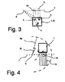
- the Fig. 3 shows the truck 1 in an operating mode as a reach truck 10.
- load arms 11 extended with load rollers 12.
- the axis of the load rollers 12 forms the transverse line 7.
- the axes of the front wheels 4 and 5 of the rear wheel are thereby aligned during cornering, that their intersection is located as a curve axis 6 on this transverse line 7. This results in the driving behavior of a known reach truck 10.
- the Fig. 4 shows the truck 1 in a mode "minimum radius" with a load 13.
- the load 13 results in the supervision of the truck 1 approximately an elongated rectangle.
- the transverse line 7 is placed in the middle of the total length of truck 1 and load.
- Ra for cornering results in a maximum inner radius Ri and thus a minimal space requirement by the arrangement of the cam axis of rotation 6.
- the required geometric conditions at the entrance, for example in a rack aisle can be optimized.
- the Fig. 5 shows the truck 1 in a "minimum radius" operating mode with the forklift tilted up and the cam pivot 14 at the center of the rectangle for minimum turnaround rotation.
- the Fig. 6 shows the truck in a "minimum radius" operating mode with the fork 3 folded down and the cam pivot 14 at the center of an enclosing rectangle for rotation in the minimum footprint.
Landscapes
- Engineering & Computer Science (AREA)
- Transportation (AREA)
- Structural Engineering (AREA)
- Civil Engineering (AREA)
- Life Sciences & Earth Sciences (AREA)
- Geology (AREA)
- Mechanical Engineering (AREA)
- Forklifts And Lifting Vehicles (AREA)
Abstract
Description
- Die Erfindung betrifft ein Verfahren zur Lenkungssteuerung bei einem Flurförderzeug. Insbesondere betrifft die Erfindung ein Verfahren zur Lenkungssteuerung bei einem Flurförderzeug bei dem alle Räder einer Vorderachse und einer Hinterachse gelenkt werden können, und das eine Anhängerkupplung und/oder eine abklappbare Lastgabel und/oder ausfahrbare Lastarme aufweist.
- Bei Flurförderzeugen sind unter anderem Gegengewichtsgabelstapler und Schubmaststapler bekannt sowie Schlepper. Bei einem Gegengewichtsgabelstapler ist es üblich, die Hinterräder oder ein einzelnes Hinterrad zu lenken, wobei die Vorderräder unterhalb bzw. nahe an einem Hubmast angeordnet sind und nicht gelenkt werden. Der Kurvenradius beim Lenken ergibt sich dann aus dem Schnittpunkt der Achsen des gelenkten hinteren Rades oder der gelenkten Hinterräder mit der Achse der Vorderräder. Der Schnittpunkt bildet eine Kurvenfahrtachse, um den die Kurvenfahrt stattfindet indem alle Räder um diese Kurvenfahrtachse Idealfall mit einem Radius auf einer Kurvenbahn laufen.
- Bei einem Schubmaststapler wird das Lastgewicht nicht überwiegend durch ein Gegengewicht ausgeglichen, sondern der Schwerpunkt der Last durch das Verschieben des Hubmastes soweit hinter die Vorderräder verbracht, dass das Fahrzeug insgesamt stabil ist. Um dies zu erreichen, sind die Vorderräder am vorderen Ende von Lastarmen, die sich nach vorn erstrecken, als Lastrollen angebracht. Auch hier wird jedoch die Kurvenfahrtachse bei Kurvenfahrt durch die Schnittpunkte der Achse dieser Lastrollen in den Lastarmen sowie der Achse eines gelenkten hinteren Rades bestimmt.
- Bei einem Schlepper dagegen werden im Regelfall die Vorderräder gelenkt und erfolgt der Antrieb über die Hinterräder, die nicht eingeschlagen werden können.
- Es sind nun Flurförderzeuge bekannt, die Kombinationen aus den zuvor geschilderten Fahrzeugen darstellen, und die daher verschiedene Betriebszustände einnehmen können. Ein solches Flurförderzeug weist beispielsweise eine Anhängerkupplung zum Schleppen von Anhängern, insbesondere eines Anhängerzuges aus mehreren Anhängern als Routenzug auf. Zusätzlich kann eine Lastaufnahmevorrichtung als Hubvorrichtung zum Ein- und Auslagern von Lasten in Regale bis zu einer gewissen Höhe genutzt werden. Hierfür ist es beispielsweise möglich, als Lastaufnahmevorrichtung eine herabklappbare Lastgabel vorzusehen, die bei einem reinen Schlepperbetrieb nach oben geklappt wird. Weiterhin ist es möglich, für schwerere Lasten Lastarme mit zusätzlichen Stützrollen vorzusehen, die ausgefahren werden können und beispielsweise eine Palette mit einem Initialhub anheben können, wobei das Gewicht der Palette bereits über die Stützrollen in diesen Lastarmen zu einem großen Teil abgestützt wird. Ein solches kombiniertes Flurförderzeug kann daher in mehreren Betriebsweisen eingesetzt werden, von denen jede einem herkömmlichen Flurförderzeug, wie etwa einem Schlepper, einem Gegengewichtsgabelstapler oder einem Schubmaststapler entspricht.
- Ein Beispiel eines solchen Flurförderzeugs, das in mehreren Funktionen eingesetzt werden kann und ausfahrbare zusätzliche Lastarme mit Lastrollen sowie klappbare Gabelzinken aufweist, ist in der
EP 2 518 005 B1 der Anmelderin offenbart. - Problematisch ist bei einem solchen kombinierten Flurförderzeug, dass sich ganz unterschiedliche Anforderungen an das Lenkverhalten stellen, je nach Art und Weise des Einsatzes. Nachteilig ist insbesondere, dass sich ein ungewohntes Fahrverhalten ergibt, soweit die Lenkung die Kurvenfahrtachse entsprechend einer bekannten Art von Flurförderzeug auf einer verlängerten starken Achse aufweist und dies abweicht von dem Verhalten eines üblichen Flurförderzeugs für eine gewählte Betriebsweise ist. Auch erfordert das Drehen des Flurförderzeugs dann eventuell relativ viel Platz, abhängig von dem gerade genutzten Betriebsmodus des Flurförderzeugs. Bei großen, bzw. sperrigen aufgenommenen Lasten kann der Platzbedarf sich ungünstig noch weiter vergrößern.
- Schließlich ist es auch wünschenswert, den benötigten Raum für eine Kurvenfahrt zu optimieren, wenn ein Flurförderzeug in eine Lagergasse eines Regallagers einbiegt.
- Es ist weiterhin bekannt, Flurförderzeuge als 4-Wegestapler auszuführen, bei denen 4 oder 3 Räder alle gelenkt werden können. Diese Stapler dienen hauptsächlich dazu, Lasten mit großer Längserstreckung, wie Rohre, Balken oder Ähnliches seitlich aufzunehmen und in Längsrichtung dieser Lasten zu transportieren.
- Der vorliegenden Erfindung liegt die Aufgabe zugrunde, ein Verfahren zur Lenkungssteuerung bei einem Flurförderzeug zur Verfügung zu stellen, durch das ein der Betriebsweise entsprechendes und gewohntes Lenkverhalten erreicht und der Platzbedarf für eine Kurvenfahrt minimiert wird.
- Diese Aufgabe wird durch ein Verfahren zur Lenkungssteuerung bei einem Flurförderzeug mit den Merkmalen des unabhängigen Patentanspruchs 1 gelöst. Vorteilhafte Weiterbildungen der Erfindung sind in den Unteransprüchen angegeben.
- Die Aufgabe wird erfindungsgemäß dadurch gelöst, dass bei einem Verfahren zur Lenkungssteuerung bei einem Flurförderzeug, bei dem alle Räder einer Vorderachse und einer Hinterachse gelenkt werden können, und das eine Anhängerkupplung und/oder eine abklappbare Lastgabel und/oder ausfahrbare Lastarme aufweist, alle Räder mit ihren Achsen auf einen gemeinsamen Schnittpunkt als Kurvendrehachse ausgerichtet werden, wobei die Kurvendrehachse auf eine Querlinie zur Fahrzeuglängsachse abhängig von einem Betriebsmodus von einer Steuerung eingestellt wird und der Betriebsmodus aus mindestens zwei der folgenden gewählt werden kann:
- Schlepper mit der Querlinie auf Höhe der Hinterräder
- Gegengewichtsgabelstapler mit der Querlinie auf Höhe der Vorderräder
- Schubmaststapler mit der Querlinie auf Höhe von Lastrollen in den ausgefahrenen Lastarmen
- Minimalradius mit der Querlinie auf halber Länge der Gesamterstreckung von Flurförderzeug einschließlich einer eventuellen aufgenommenen Last.
- Dadurch ergibt sich stets ein optimales bzw. gewohntes Fahrverhalten, soweit das Flurförderzeug durch einen Fahrer gesteuert wird, indem eine Anpassung des Lenkverhaltens an den aktiven Betriebsmodus erfolgt. Es ist keine Umgewöhnung bei einem Wechsel des Betriebsmodus erforderlich, da das Flurförderzeug ein bekanntes Verhalten aufweist. So werden beim Betrieb als Schlepper nur die Vorderräder gelenkt, bei einem Betrieb als Gegengewichtsgabelstapler die Hinterräder so gelenkt, dass die Querlinie mit der Kurvendrehachse sich in der Achse der beiden gerade gestellten Vorderräder befindet. Wenn zusätzliche Lastarme ausgefahren werden mit Lastrollen, entsprechend einer Art Schubmaststapler, so werden alle gelenkten Räder der Vorderachse und Hinterachse so eingestellt, dass die Querlinie auf die Achse der Lastrollen fällt. Abhängig von dem gewünschten, zu fahrenden Kurvenradius, bewegt sich dann die Kurvendrehachse auf der Querlinie von unendlich her mit kleiner werdendem, zu fahrenden Kurvenradius an die Mittelachse des Flurförderzeugs heran. Bei dem hier beschriebenen Verfahren wird von der Steuerung zwischen mindestens zwei oder allen beschriebenen Betriebsmodi gewählt. Grundsätzlich ist es jedoch auch denkbar, eine Lenkungssteuerung durchzuführen, bei der die Kurvendrehachse über die beschriebenen Positionen auf diesen Querlinien hinaus und unabhängig von einer solchen Einteilung in Betriebsmodi völlig frei gewählt wird. Insbesondere ist dies denkbar bei einem autonomen, fahrerlosen Fahrzeug, bei dem etwa eine Bewegung der Ausrichtung des Flurförderzeugs und der Kurvenfahrt überlagert werden können oder beispielsweise eine Optimierung an örtliche Fahrwege erfolgen kann.
- Vorteilhaft werden alle gelenkten Räder angetrieben.
- Dadurch wird vermieden, dass es zu Selbsthemmungen durch die sehr freie Wahl der Kurvendrehachse kommt und können auch bei großen Einschlagwinkeln ausreichend Antriebskräfte übertragen werden.
- In einer Weiterbildung des Verfahrens weist das Flurförderzeug eine Lastgabel und/oder Lastarme auf und werden für eine Querbewegung der Lastgabel und/oder der Lastarme die gelenkten Räder quer zu einer Längsachse des Fahrzeugs von der Steuerung gestellt.
- Dadurch kann bei einer ausgeklappten Lastgabel oder ausgefahrenen Lastarmen, bei letzterem soweit dies die Lastrollen zulassen, eine Querbewegung erfolgen. Es wird keine Querschubvorrichtung erforderlich und kann die Funktion des Querschubs allein durch das beschriebene Lenkungssteuerungsverfahren verwirklicht werden.
- Der Betriebsmodus Minimalradius kann gewählt werden und die Kurvendrehachse in dem Betriebsmodus Minimalradius für eine Drehung auf der Stelle in den Schnittpunkt der Querlinie mit einer Fahrzeuglängsachse von der Steuerung gelegt wird.
- In Aufsicht betrachtet stellt ein Flurförderzeug mit einer Last im Wesentlichen ein Rechteck da. Dabei kann die Länge und im Ausnahmefall auch die Breite des Rechtecks durch die Größe und Form der Last mitbestimmt werden. Der optimierte, minimale Platzbedarf zwischen einer äußeren Tangentenkreisbahn an diesem Rechteck über die äußeren Ecken sowie einer inneren Tangentenkreisbahn in der Mitte der Längserstreckung ergibt sich näherungsweise, soweit die Last nicht seitlich über das Flurförderzeug hinaus steht, mit konzentrischen Tangentenkreisbahnen, deren Mittelpunkt auf einer Querlinie auf halber Länge der Längserstreckung des Flurförderzeugs mit der Last liegt. Wird die Kurvendrehachse auf diese Querlinie gelegt, so ergibt sich eine optimierte, platzsparende Kurvenfahrt, durch die optimierte Abstände der Regalgassen ermöglicht werden. Wird die Kurvendrehachse dabei auf dieser Querlinie genau in die Mitte des Rechtecks gelegt, ergibt sich eine Drehung auf der Stelle mit minimalem Platzbedarf.
- Es kann der Betriebsmodus Minimalradius gewählt werden und die Steuerung von Sensoren Daten über die Abmessungen einer aufgenommenen Last erhalten.
- Vorteilhaft kann der Betriebsmodus Minimalradius gewählt werden und die Steuerung von einer Datenverbindung, insbesondere aus einem Netzwerk von einem Warenwirtschaftssystem, Daten über die Abmessungen einer aufzunehmenden Last erhalten.
- Dadurch kann die Steuerung vorteilhaft die Geometrie des Flurförderzeugs in Aufsicht einschließlich der Last bestimmen und eine Querlinie auf halber Längserstreckung festlegen.
- In einer Weiterbildung des Verfahrens kann das Flurförderzeug autonom betrieben werden kann ohne Fahrer.
- Insbesondere, wenn ein wechselweise Betrieb sowohl mit Fahrer wie auch ohne Fahrer möglich ist, kann der Betriebsmodus mit einem minimalen Radius im autonomen Betrieb gewählt werden, ohne dass für einen Fahrer ein ungewohntes Fahrverhalten auftritt.
- Weitere Vorteile und Einzelheiten der Erfindung werden anhand der in den schematischen Figuren dargestellten Ausführungsbeispiele näher erläutert. Hierbei zeigt
- Fig. 1
- ein erfindungsgemäßes Flurförderzeug in einem Betriebsmodus als Gegengewichtsgabelstapler,
- Fig. 2
- das Flurförderzeug in einem Betriebsmodus als Schlepper,
- Fig. 3
- das Flurförderzeug in einem Betriebsmodus als Schubmaststapler,
- Fig. 4
- das Flurförderzeug in einem Betriebsmodus "Minimalradius" mit einer Last,
- Fig. 5
- das Flurförderzeug in einem Betriebsmodus "Minimalradius" mit hochgeklappter Lastgabel und
- Fig. 6
- das Flurförderzeug in einem Betriebsmodus "Minimalradius" mit abgeklappter Lastgabel.
- Die
Fig. 1 zeigt ein erfindungsgemäßes Flurförderzeug 1 in einem Betriebsmodus als Gegengewichtsgabelstapler 2, bei dem eine Lastgabel 3 heruntergeklappt ist. Vorderräder 4 sind dabei in eine gerade Stellung verbracht und werden nicht gelenkt. Ein einzelnes Hinterrad 5 des als Dreiradfahrzeug ausgeführten Flurförderzeugs 1, wird so ausgerichtet, dass eine Kurvendrehachse 6 abhängig von dem zu fahrenden Kurvenradius auf einer Querlinie 7 sich bewegt, die der Achse der Vorderräder 4 entspricht. Dadurch ergibt sich für einen Fahrer das Fahrverhalten eines bekannten Gegengewichtsgabelstaplers 2. - Die
Fig. 2 zeigt das Flurförderzeug 1 in einem Betriebsmodus als Schlepper 8, an den ein Anhänger 9 gekuppelt ist. Hier wird das Hinterrad 5 in der geraden Stellung gehalten und die Querlinie 7 entspricht der Achse des Hinterrads 5. Die Vorderräder 4 werden so ausgerichtet, dass deren Schnittpunkt bzw. die Kurvendrehachse 6 sich auf der Querlinie 7 bewegt. Es ergibt sich somit für dasselbe Flurförderzeug allein durch die Auswahl des Betriebsmodus das Fahrverhalten eines bekannten Schleppers 8. - Die
Fig. 3 zeigt das Flurförderzeug 1 in einem Betriebsmodus als Schubmaststapler 10. Dabei sind Lastarme 11 mit Lastrollen 12 ausgefahren. Die Achse der Lastrollen 12 bildet die Querlinie 7. Die Achsen der Vorderräder 4 und des Hinterrades 5 werden dabei so ausgerichtet bei einer Kurvenfahrt, dass deren Schnittpunkt als Kurvendrehachse 6 auf dieser Querlinie 7 liegt. Es ergibt sich somit das Fahrverhalten eines bekannten Schubmaststaplers 10. - Die
Fig. 4 zeigt das Flurförderzeug 1 in einem Betriebsmodus "Minimalradius" mit einer Last 13. Durch die Last 13 ergibt sich in der Aufsicht für das Flurförderzeug 1 näherungsweise ein verlängertes Rechteck. Um einen minimalen Radius und Fahrweg für eine Kurvenfahrt zu erreichen, wird die Querlinie 7 dabei in die Mitte der Gesamtlänge aus Flurförderzeug 1 und Last gelegt. Bei einem vorgegebenen Außenradius Ra für die Kurvenfahrt ergibt sich dabei ein maximaler Innenradius Ri und somit ein minimaler Platzbedarf durch die Anordnung der Kurvendrehachse 6. Die erforderlichen geometrischen Verhältnisse bei der Einfahrt beispielsweise in eine Regalgasse können dadurch optimiert werden. - Wird eine Kurvendrehachse 14 in den Mittelpunkt des Rechtecks bzw. den Schnittpunkt der Querlinie 7 mit einer Fahrzeugmittelachse gelegt, kann mit minimalem Platz eine Drehung auf der Stelle erfolgen, wie durch den Pfeil in der Darstellung der
Fig. 4 angedeutet. - Die
Fig. 5 zeigt das Flurförderzeug 1 in einem Betriebsmodus "Minimalradius" mit hochgeklappter Lastgabel und der Kurvendrehachse 14 in dem Mittelpunkt des Rechtecks für eine Drehung auf der Stelle mit minimalem Platzbedarf. - Die
Fig. 6 zeigt das Flurförderzeug in einem Betriebsmodus "Minimalradius" mit abgeklappter Lastgabel 3 und der Kurvendrehachse 14 in dem Mittelpunkt eines umschließenden Rechtecks für eine Drehung auf der Stelle mit minimalem Platzbedarf.
Claims (7)
- Verfahren zur Lenkungssteuerung bei einem Flurförderzeug (1), bei dem alle Räder einer Vorderachse (4) und einer Hinterachse (5) gelenkt werden können, und das eine Anhängerkupplung und/oder eine abklappbare Lastgabel (3) und/oder ausfahrbare Lastarme (11) aufweist,
dadurch gekennzeichnet,
dass alle Räder (4,5) mit ihren Achsen auf einen gemeinsamen Schnittpunkt als Kurvendrehachse (6,14) ausgerichtet werden, wobei die Kurvendrehachse auf eine Querlinie (7) zur Fahrzeuglängsachse abhängig von einem Betriebsmodus von einer Steuerung eingestellt wird und der Betriebsmodus aus mindestens zwei der folgenden gewählt werden kann:- Schlepper (8) mit der Querlinie (7) auf Höhe der Hinterräder (5)- Gegengewichtsgabelstapler (2) mit der Querlinie (7) auf Höhe der Vorderräder (4)- Schubmaststapler (10) mit der Querlinie (7) auf Höhe von Lastrollen (12) in den ausgefahrenen Lastarmen (11)- Minimalradius mit der Querlinie (7) auf halber Länge der Gesamterstreckung von Flurförderzeug (1) einschließlich einer eventuellen aufgenommenen Last (13). - Verfahren nach Anspruch 1,
dadurch gekennzeichnet,
dass alle gelenkten Räder (4,5) angetrieben werden. - Verfahren nach Anspruch 2,
dadurch gekennzeichnet,
dass das Flurförderzeug (1) eine Lastgabel (3) und/oder Lastarme (11) aufweist und für eine Querbewegung der Lastgabel (3) und/oder der Lastarme (11) die gelenkten Räder (4,5) quer zu einer Längsachse des Fahrzeugs von der Steuerung gestellt werden. - Verfahren nach einem der Ansprüche 1 bis 3,
dadurch gekennzeichnet,
dass der Betriebsmodus Minimalradius gewählt werden kann und die Kurvendrehachse (14) in dem Betriebsmodus Minimalradius für eine Drehung auf der Stelle in den Schnittpunkt der Querlinie (7) mit einer Fahrzeuglängsachse von der Steuerung gelegt wird. - Verfahren nach einem der Ansprüche 1 bis 4,
dadurch gekennzeichnet,
dass der Betriebsmodus Minimalradius gewählt werden kann und die Steuerung von Sensoren Daten über die Abmessungen einer aufgenommenen Last (13) erhält. - Verfahren nach einem der Ansprüche 1 bis 5,
dadurch gekennzeichnet,
dass der Betriebsmodus Minimalradius gewählt werden kann und die Steuerung von einer Datenverbindung, insbesondere aus einem Netzwerk von einem Warenwirtschaftssystem, Daten über die Abmessungen einer aufzunehmenden Last (13) erhält. - Verfahren nach einem der Ansprüche 1 bis 6,
dadurch gekennzeichnet,
dass das Flurförderzeug (1) autonom betrieben werden kann ohne Fahrer.
Applications Claiming Priority (1)
| Application Number | Priority Date | Filing Date | Title |
|---|---|---|---|
| DE102014107065.8A DE102014107065A1 (de) | 2014-05-19 | 2014-05-19 | Verfahren zur Lenkungssteuerung bei einem Flurförderzeug |
Publications (2)
| Publication Number | Publication Date |
|---|---|
| EP2947044A1 true EP2947044A1 (de) | 2015-11-25 |
| EP2947044B1 EP2947044B1 (de) | 2017-12-27 |
Family
ID=53189632
Family Applications (1)
| Application Number | Title | Priority Date | Filing Date |
|---|---|---|---|
| EP15166727.6A Not-in-force EP2947044B1 (de) | 2014-05-19 | 2015-05-07 | Verfahren zur lenkungssteuerung bei einem flurförderzeug |
Country Status (2)
| Country | Link |
|---|---|
| EP (1) | EP2947044B1 (de) |
| DE (1) | DE102014107065A1 (de) |
Families Citing this family (1)
| Publication number | Priority date | Publication date | Assignee | Title |
|---|---|---|---|---|
| DE102022132928B4 (de) * | 2022-12-12 | 2026-05-07 | Hubtex Maschinenbau Gmbh & Co. Kg | Lenkverfahren zum Betrieb eines Flurförderzeugs, Flurförderzeug |
Citations (4)
| Publication number | Priority date | Publication date | Assignee | Title |
|---|---|---|---|---|
| WO2007036767A1 (en) * | 2005-09-28 | 2007-04-05 | Cesab Carrelli Elevatori S.P.A. | Forklift truck steering device and forklift truck |
| WO2008141836A1 (en) * | 2007-05-24 | 2008-11-27 | Martin Mcvicar | Three-wheel foklift truck |
| EP2518005B1 (de) | 2011-04-27 | 2013-09-18 | STILL GmbH | Flurförderzeug |
| US20140074342A1 (en) * | 2011-09-07 | 2014-03-13 | Crown Equipment Limited | Method and apparatus for using pre-positioned objects to localize an industrial vehicle |
-
2014
- 2014-05-19 DE DE102014107065.8A patent/DE102014107065A1/de not_active Withdrawn
-
2015
- 2015-05-07 EP EP15166727.6A patent/EP2947044B1/de not_active Not-in-force
Patent Citations (4)
| Publication number | Priority date | Publication date | Assignee | Title |
|---|---|---|---|---|
| WO2007036767A1 (en) * | 2005-09-28 | 2007-04-05 | Cesab Carrelli Elevatori S.P.A. | Forklift truck steering device and forklift truck |
| WO2008141836A1 (en) * | 2007-05-24 | 2008-11-27 | Martin Mcvicar | Three-wheel foklift truck |
| EP2518005B1 (de) | 2011-04-27 | 2013-09-18 | STILL GmbH | Flurförderzeug |
| US20140074342A1 (en) * | 2011-09-07 | 2014-03-13 | Crown Equipment Limited | Method and apparatus for using pre-positioned objects to localize an industrial vehicle |
Also Published As
| Publication number | Publication date |
|---|---|
| EP2947044B1 (de) | 2017-12-27 |
| DE102014107065A1 (de) | 2015-11-19 |
Similar Documents
| Publication | Publication Date | Title |
|---|---|---|
| EP0916615B1 (de) | Fahrerloses, z.B. frei navigierendes Transportfahrzeug zum Handhaben von Lasten | |
| EP1447374B1 (de) | Stapler | |
| EP3048079B1 (de) | Flurförderzeug | |
| WO2017153397A1 (de) | Fahrerloses transportfahrzeug | |
| DE1455868A1 (de) | Flurfoerderfahrzeug | |
| EP3689812A1 (de) | Flurförderzeug mit einem mehrrädrigen fahrwerk | |
| EP2947044B1 (de) | Verfahren zur lenkungssteuerung bei einem flurförderzeug | |
| EP3848324B1 (de) | Fahrerloses transportfahrzeug | |
| DE102021121222A1 (de) | Autonom geführtes Flurförderzeug mit einem Paar von Scanner-Einheiten | |
| EP2944601B1 (de) | Autonomes fahrerloses transportfahrzeug und transportsystem | |
| DE102008062727A1 (de) | Transportwagen | |
| DE20117198U1 (de) | Mehrwegetransportfahrzeug, insbesondere Mehrwegestapler | |
| EP3543096B1 (de) | Flurförderzeug mit einem lastrahmen für fahrbare lastträger | |
| AT523117A1 (de) | Fahrerlose transporteinrichtung zum transportieren eines ladungsträgers | |
| WO2024126005A1 (de) | Lenkverfahren zum betrieb eines flurförderzeugs, flurförderzeug | |
| EP3689709A1 (de) | Fahrplattform | |
| DE102005014907A1 (de) | Niederhub-Flurförderzeug | |
| EP4541696B1 (de) | Baufahrzeug | |
| DE102021214305A1 (de) | Transportfahrzeug und Transportfahrzeugzug | |
| DE3214391A1 (de) | Selbstfahrendes fahrzeug | |
| DE102020133568A1 (de) | Flurförderzeug mit gegengewicht-verlagerungseinheit | |
| DE102022132928B4 (de) | Lenkverfahren zum Betrieb eines Flurförderzeugs, Flurförderzeug | |
| DE20007291U1 (de) | Regalstapler mit Koordinatenfahrwerk, vollautomatisch | |
| EP2518005A1 (de) | Flurförderzeug | |
| DE889277C (de) | Fahrstapler |
Legal Events
| Date | Code | Title | Description |
|---|---|---|---|
| PUAI | Public reference made under article 153(3) epc to a published international application that has entered the european phase |
Free format text: ORIGINAL CODE: 0009012 |
|
| AK | Designated contracting states |
Kind code of ref document: A1 Designated state(s): AL AT BE BG CH CY CZ DE DK EE ES FI FR GB GR HR HU IE IS IT LI LT LU LV MC MK MT NL NO PL PT RO RS SE SI SK SM TR |
|
| AX | Request for extension of the european patent |
Extension state: BA ME |
|
| RIN1 | Information on inventor provided before grant (corrected) |
Inventor name: KRUEGER-BASJMELEH, TINO Inventor name: CARO, SOENKE Inventor name: VIERECK, VOLKER Inventor name: WITTMANN, THOMAS Inventor name: KLUG, MATTHIAS |
|
| 17P | Request for examination filed |
Effective date: 20160524 |
|
| RBV | Designated contracting states (corrected) |
Designated state(s): AL AT BE BG CH CY CZ DE DK EE ES FI FR GB GR HR HU IE IS IT LI LT LU LV MC MK MT NL NO PL PT RO RS SE SI SK SM TR |
|
| RIN1 | Information on inventor provided before grant (corrected) |
Inventor name: KLUG, MATTHIAS Inventor name: KRUEGER-BASJMELEH, TINO Inventor name: WITTMANN, THOMAS Inventor name: VIERECK, VOLKER Inventor name: CARO, SOENKE Inventor name: BAERWOLFF, CHRISTIAN |
|
| GRAP | Despatch of communication of intention to grant a patent |
Free format text: ORIGINAL CODE: EPIDOSNIGR1 |
|
| STAA | Information on the status of an ep patent application or granted ep patent |
Free format text: STATUS: GRANT OF PATENT IS INTENDED |
|
| INTG | Intention to grant announced |
Effective date: 20170703 |
|
| GRAS | Grant fee paid |
Free format text: ORIGINAL CODE: EPIDOSNIGR3 |
|
| GRAA | (expected) grant |
Free format text: ORIGINAL CODE: 0009210 |
|
| STAA | Information on the status of an ep patent application or granted ep patent |
Free format text: STATUS: THE PATENT HAS BEEN GRANTED |
|
| AK | Designated contracting states |
Kind code of ref document: B1 Designated state(s): AL AT BE BG CH CY CZ DE DK EE ES FI FR GB GR HR HU IE IS IT LI LT LU LV MC MK MT NL NO PL PT RO RS SE SI SK SM TR |
|
| REG | Reference to a national code |
Ref country code: GB Ref legal event code: FG4D Free format text: NOT ENGLISH |
|
| RIN1 | Information on inventor provided before grant (corrected) |
Inventor name: KRUEGER-BASJMELEH, TINO Inventor name: WITTMANN, THOMAS Inventor name: BAERWOLFF, CHRISTIAN Inventor name: CARO, SOENKE Inventor name: VIERECK, VOLKER Inventor name: KLUG, MATTHIAS |
|
| REG | Reference to a national code |
Ref country code: CH Ref legal event code: EP |
|
| REG | Reference to a national code |
Ref country code: AT Ref legal event code: REF Ref document number: 958087 Country of ref document: AT Kind code of ref document: T Effective date: 20180115 |
|
| REG | Reference to a national code |
Ref country code: IE Ref legal event code: FG4D Free format text: LANGUAGE OF EP DOCUMENT: GERMAN |
|
| REG | Reference to a national code |
Ref country code: DE Ref legal event code: R096 Ref document number: 502015002666 Country of ref document: DE |
|
| PG25 | Lapsed in a contracting state [announced via postgrant information from national office to epo] |
Ref country code: FI Free format text: LAPSE BECAUSE OF FAILURE TO SUBMIT A TRANSLATION OF THE DESCRIPTION OR TO PAY THE FEE WITHIN THE PRESCRIBED TIME-LIMIT Effective date: 20171227 Ref country code: NO Free format text: LAPSE BECAUSE OF FAILURE TO SUBMIT A TRANSLATION OF THE DESCRIPTION OR TO PAY THE FEE WITHIN THE PRESCRIBED TIME-LIMIT Effective date: 20180327 Ref country code: LT Free format text: LAPSE BECAUSE OF FAILURE TO SUBMIT A TRANSLATION OF THE DESCRIPTION OR TO PAY THE FEE WITHIN THE PRESCRIBED TIME-LIMIT Effective date: 20171227 |
|
| REG | Reference to a national code |
Ref country code: NL Ref legal event code: MP Effective date: 20171227 |
|
| REG | Reference to a national code |
Ref country code: LT Ref legal event code: MG4D |
|
| REG | Reference to a national code |
Ref country code: FR Ref legal event code: PLFP Year of fee payment: 4 |
|
| PG25 | Lapsed in a contracting state [announced via postgrant information from national office to epo] |
Ref country code: HR Free format text: LAPSE BECAUSE OF FAILURE TO SUBMIT A TRANSLATION OF THE DESCRIPTION OR TO PAY THE FEE WITHIN THE PRESCRIBED TIME-LIMIT Effective date: 20171227 Ref country code: LV Free format text: LAPSE BECAUSE OF FAILURE TO SUBMIT A TRANSLATION OF THE DESCRIPTION OR TO PAY THE FEE WITHIN THE PRESCRIBED TIME-LIMIT Effective date: 20171227 Ref country code: GR Free format text: LAPSE BECAUSE OF FAILURE TO SUBMIT A TRANSLATION OF THE DESCRIPTION OR TO PAY THE FEE WITHIN THE PRESCRIBED TIME-LIMIT Effective date: 20180328 Ref country code: BG Free format text: LAPSE BECAUSE OF FAILURE TO SUBMIT A TRANSLATION OF THE DESCRIPTION OR TO PAY THE FEE WITHIN THE PRESCRIBED TIME-LIMIT Effective date: 20180327 Ref country code: RS Free format text: LAPSE BECAUSE OF FAILURE TO SUBMIT A TRANSLATION OF THE DESCRIPTION OR TO PAY THE FEE WITHIN THE PRESCRIBED TIME-LIMIT Effective date: 20171227 |
|
| PG25 | Lapsed in a contracting state [announced via postgrant information from national office to epo] |
Ref country code: NL Free format text: LAPSE BECAUSE OF FAILURE TO SUBMIT A TRANSLATION OF THE DESCRIPTION OR TO PAY THE FEE WITHIN THE PRESCRIBED TIME-LIMIT Effective date: 20171227 |
|
| PG25 | Lapsed in a contracting state [announced via postgrant information from national office to epo] |
Ref country code: SK Free format text: LAPSE BECAUSE OF FAILURE TO SUBMIT A TRANSLATION OF THE DESCRIPTION OR TO PAY THE FEE WITHIN THE PRESCRIBED TIME-LIMIT Effective date: 20171227 Ref country code: CY Free format text: LAPSE BECAUSE OF FAILURE TO SUBMIT A TRANSLATION OF THE DESCRIPTION OR TO PAY THE FEE WITHIN THE PRESCRIBED TIME-LIMIT Effective date: 20171227 Ref country code: ES Free format text: LAPSE BECAUSE OF FAILURE TO SUBMIT A TRANSLATION OF THE DESCRIPTION OR TO PAY THE FEE WITHIN THE PRESCRIBED TIME-LIMIT Effective date: 20171227 Ref country code: CZ Free format text: LAPSE BECAUSE OF FAILURE TO SUBMIT A TRANSLATION OF THE DESCRIPTION OR TO PAY THE FEE WITHIN THE PRESCRIBED TIME-LIMIT Effective date: 20171227 Ref country code: EE Free format text: LAPSE BECAUSE OF FAILURE TO SUBMIT A TRANSLATION OF THE DESCRIPTION OR TO PAY THE FEE WITHIN THE PRESCRIBED TIME-LIMIT Effective date: 20171227 |
|
| PG25 | Lapsed in a contracting state [announced via postgrant information from national office to epo] |
Ref country code: IS Free format text: LAPSE BECAUSE OF FAILURE TO SUBMIT A TRANSLATION OF THE DESCRIPTION OR TO PAY THE FEE WITHIN THE PRESCRIBED TIME-LIMIT Effective date: 20180427 Ref country code: SM Free format text: LAPSE BECAUSE OF FAILURE TO SUBMIT A TRANSLATION OF THE DESCRIPTION OR TO PAY THE FEE WITHIN THE PRESCRIBED TIME-LIMIT Effective date: 20171227 Ref country code: PL Free format text: LAPSE BECAUSE OF FAILURE TO SUBMIT A TRANSLATION OF THE DESCRIPTION OR TO PAY THE FEE WITHIN THE PRESCRIBED TIME-LIMIT Effective date: 20171227 Ref country code: RO Free format text: LAPSE BECAUSE OF FAILURE TO SUBMIT A TRANSLATION OF THE DESCRIPTION OR TO PAY THE FEE WITHIN THE PRESCRIBED TIME-LIMIT Effective date: 20171227 |
|
| PG25 | Lapsed in a contracting state [announced via postgrant information from national office to epo] |
Ref country code: MT Free format text: LAPSE BECAUSE OF FAILURE TO SUBMIT A TRANSLATION OF THE DESCRIPTION OR TO PAY THE FEE WITHIN THE PRESCRIBED TIME-LIMIT Effective date: 20171227 |
|
| REG | Reference to a national code |
Ref country code: DE Ref legal event code: R097 Ref document number: 502015002666 Country of ref document: DE |
|
| PLBE | No opposition filed within time limit |
Free format text: ORIGINAL CODE: 0009261 |
|
| STAA | Information on the status of an ep patent application or granted ep patent |
Free format text: STATUS: NO OPPOSITION FILED WITHIN TIME LIMIT |
|
| PG25 | Lapsed in a contracting state [announced via postgrant information from national office to epo] |
Ref country code: DK Free format text: LAPSE BECAUSE OF FAILURE TO SUBMIT A TRANSLATION OF THE DESCRIPTION OR TO PAY THE FEE WITHIN THE PRESCRIBED TIME-LIMIT Effective date: 20171227 |
|
| 26N | No opposition filed |
Effective date: 20180928 |
|
| REG | Reference to a national code |
Ref country code: CH Ref legal event code: PL |
|
| REG | Reference to a national code |
Ref country code: BE Ref legal event code: MM Effective date: 20180531 |
|
| PG25 | Lapsed in a contracting state [announced via postgrant information from national office to epo] |
Ref country code: MC Free format text: LAPSE BECAUSE OF FAILURE TO SUBMIT A TRANSLATION OF THE DESCRIPTION OR TO PAY THE FEE WITHIN THE PRESCRIBED TIME-LIMIT Effective date: 20171227 |
|
| REG | Reference to a national code |
Ref country code: IE Ref legal event code: MM4A |
|
| PG25 | Lapsed in a contracting state [announced via postgrant information from national office to epo] |
Ref country code: LI Free format text: LAPSE BECAUSE OF NON-PAYMENT OF DUE FEES Effective date: 20180531 Ref country code: CH Free format text: LAPSE BECAUSE OF NON-PAYMENT OF DUE FEES Effective date: 20180531 Ref country code: SI Free format text: LAPSE BECAUSE OF FAILURE TO SUBMIT A TRANSLATION OF THE DESCRIPTION OR TO PAY THE FEE WITHIN THE PRESCRIBED TIME-LIMIT Effective date: 20171227 |
|
| PG25 | Lapsed in a contracting state [announced via postgrant information from national office to epo] |
Ref country code: LU Free format text: LAPSE BECAUSE OF NON-PAYMENT OF DUE FEES Effective date: 20180507 |
|
| PG25 | Lapsed in a contracting state [announced via postgrant information from national office to epo] |
Ref country code: IE Free format text: LAPSE BECAUSE OF NON-PAYMENT OF DUE FEES Effective date: 20180507 |
|
| PG25 | Lapsed in a contracting state [announced via postgrant information from national office to epo] |
Ref country code: BE Free format text: LAPSE BECAUSE OF NON-PAYMENT OF DUE FEES Effective date: 20180531 |
|
| GBPC | Gb: european patent ceased through non-payment of renewal fee |
Effective date: 20190507 |
|
| PG25 | Lapsed in a contracting state [announced via postgrant information from national office to epo] |
Ref country code: TR Free format text: LAPSE BECAUSE OF FAILURE TO SUBMIT A TRANSLATION OF THE DESCRIPTION OR TO PAY THE FEE WITHIN THE PRESCRIBED TIME-LIMIT Effective date: 20171227 |
|
| PG25 | Lapsed in a contracting state [announced via postgrant information from national office to epo] |
Ref country code: GB Free format text: LAPSE BECAUSE OF NON-PAYMENT OF DUE FEES Effective date: 20190507 |
|
| PG25 | Lapsed in a contracting state [announced via postgrant information from national office to epo] |
Ref country code: PT Free format text: LAPSE BECAUSE OF FAILURE TO SUBMIT A TRANSLATION OF THE DESCRIPTION OR TO PAY THE FEE WITHIN THE PRESCRIBED TIME-LIMIT Effective date: 20171227 |
|
| PG25 | Lapsed in a contracting state [announced via postgrant information from national office to epo] |
Ref country code: HU Free format text: LAPSE BECAUSE OF FAILURE TO SUBMIT A TRANSLATION OF THE DESCRIPTION OR TO PAY THE FEE WITHIN THE PRESCRIBED TIME-LIMIT; INVALID AB INITIO Effective date: 20150507 Ref country code: MK Free format text: LAPSE BECAUSE OF NON-PAYMENT OF DUE FEES Effective date: 20171227 Ref country code: SE Free format text: LAPSE BECAUSE OF FAILURE TO SUBMIT A TRANSLATION OF THE DESCRIPTION OR TO PAY THE FEE WITHIN THE PRESCRIBED TIME-LIMIT Effective date: 20171227 |
|
| PG25 | Lapsed in a contracting state [announced via postgrant information from national office to epo] |
Ref country code: AL Free format text: LAPSE BECAUSE OF FAILURE TO SUBMIT A TRANSLATION OF THE DESCRIPTION OR TO PAY THE FEE WITHIN THE PRESCRIBED TIME-LIMIT Effective date: 20171227 |
|
| REG | Reference to a national code |
Ref country code: AT Ref legal event code: MM01 Ref document number: 958087 Country of ref document: AT Kind code of ref document: T Effective date: 20200507 |
|
| PGFP | Annual fee paid to national office [announced via postgrant information from national office to epo] |
Ref country code: FR Payment date: 20210525 Year of fee payment: 7 Ref country code: DE Payment date: 20210525 Year of fee payment: 7 Ref country code: IT Payment date: 20210531 Year of fee payment: 7 |
|
| PG25 | Lapsed in a contracting state [announced via postgrant information from national office to epo] |
Ref country code: AT Free format text: LAPSE BECAUSE OF NON-PAYMENT OF DUE FEES Effective date: 20200507 |
|
| REG | Reference to a national code |
Ref country code: DE Ref legal event code: R119 Ref document number: 502015002666 Country of ref document: DE |
|
| PG25 | Lapsed in a contracting state [announced via postgrant information from national office to epo] |
Ref country code: FR Free format text: LAPSE BECAUSE OF NON-PAYMENT OF DUE FEES Effective date: 20220531 |
|
| PG25 | Lapsed in a contracting state [announced via postgrant information from national office to epo] |
Ref country code: DE Free format text: LAPSE BECAUSE OF NON-PAYMENT OF DUE FEES Effective date: 20221201 |
|
| PG25 | Lapsed in a contracting state [announced via postgrant information from national office to epo] |
Ref country code: IT Free format text: LAPSE BECAUSE OF NON-PAYMENT OF DUE FEES Effective date: 20220507 |