EP2946937B1 - Druckvorrichtung und zugehöriges verfahren - Google Patents
Druckvorrichtung und zugehöriges verfahren Download PDFInfo
- Publication number
- EP2946937B1 EP2946937B1 EP15168738.1A EP15168738A EP2946937B1 EP 2946937 B1 EP2946937 B1 EP 2946937B1 EP 15168738 A EP15168738 A EP 15168738A EP 2946937 B1 EP2946937 B1 EP 2946937B1
- Authority
- EP
- European Patent Office
- Prior art keywords
- printing
- article
- heads
- belt
- head
- Prior art date
- Legal status (The legal status is an assumption and is not a legal conclusion. Google has not performed a legal analysis and makes no representation as to the accuracy of the status listed.)
- Active
Links
- 238000007639 printing Methods 0.000 title claims description 202
- 238000000034 method Methods 0.000 title claims description 21
- 238000001035 drying Methods 0.000 claims description 13
- 230000015572 biosynthetic process Effects 0.000 claims description 3
- 239000000463 material Substances 0.000 description 40
- 239000003086 colorant Substances 0.000 description 6
- 238000009472 formulation Methods 0.000 description 4
- 239000000203 mixture Substances 0.000 description 4
- 239000011111 cardboard Substances 0.000 description 3
- 230000000694 effects Effects 0.000 description 3
- 239000000975 dye Substances 0.000 description 2
- 239000004744 fabric Substances 0.000 description 2
- 239000011521 glass Substances 0.000 description 2
- 239000000976 ink Substances 0.000 description 2
- 239000007769 metal material Substances 0.000 description 2
- 238000012986 modification Methods 0.000 description 2
- 230000004048 modification Effects 0.000 description 2
- 239000003973 paint Substances 0.000 description 2
- 239000000123 paper Substances 0.000 description 2
- 239000004033 plastic Substances 0.000 description 2
- 238000007792 addition Methods 0.000 description 1
- 238000005352 clarification Methods 0.000 description 1
- 230000001419 dependent effect Effects 0.000 description 1
- 238000000151 deposition Methods 0.000 description 1
- 238000007641 inkjet printing Methods 0.000 description 1
- 230000001678 irradiating effect Effects 0.000 description 1
- 230000003287 optical effect Effects 0.000 description 1
- 238000005086 pumping Methods 0.000 description 1
- 238000003466 welding Methods 0.000 description 1
Images
Classifications
-
- B—PERFORMING OPERATIONS; TRANSPORTING
- B41—PRINTING; LINING MACHINES; TYPEWRITERS; STAMPS
- B41J—TYPEWRITERS; SELECTIVE PRINTING MECHANISMS, i.e. MECHANISMS PRINTING OTHERWISE THAN FROM A FORME; CORRECTION OF TYPOGRAPHICAL ERRORS
- B41J25/00—Actions or mechanisms not otherwise provided for
- B41J25/304—Bodily-movable mechanisms for print heads or carriages movable towards or from paper surface
- B41J25/308—Bodily-movable mechanisms for print heads or carriages movable towards or from paper surface with print gap adjustment mechanisms
-
- B—PERFORMING OPERATIONS; TRANSPORTING
- B41—PRINTING; LINING MACHINES; TYPEWRITERS; STAMPS
- B41J—TYPEWRITERS; SELECTIVE PRINTING MECHANISMS, i.e. MECHANISMS PRINTING OTHERWISE THAN FROM A FORME; CORRECTION OF TYPOGRAPHICAL ERRORS
- B41J11/00—Devices or arrangements of selective printing mechanisms, e.g. ink-jet printers or thermal printers, for supporting or handling copy material in sheet or web form
- B41J11/0015—Devices or arrangements of selective printing mechanisms, e.g. ink-jet printers or thermal printers, for supporting or handling copy material in sheet or web form for treating before, during or after printing or for uniform coating or laminating the copy material before or after printing
- B41J11/002—Curing or drying the ink on the copy materials, e.g. by heating or irradiating
- B41J11/0021—Curing or drying the ink on the copy materials, e.g. by heating or irradiating using irradiation
- B41J11/00214—Curing or drying the ink on the copy materials, e.g. by heating or irradiating using irradiation using UV radiation
-
- B—PERFORMING OPERATIONS; TRANSPORTING
- B41—PRINTING; LINING MACHINES; TYPEWRITERS; STAMPS
- B41J—TYPEWRITERS; SELECTIVE PRINTING MECHANISMS, i.e. MECHANISMS PRINTING OTHERWISE THAN FROM A FORME; CORRECTION OF TYPOGRAPHICAL ERRORS
- B41J11/00—Devices or arrangements of selective printing mechanisms, e.g. ink-jet printers or thermal printers, for supporting or handling copy material in sheet or web form
- B41J11/0015—Devices or arrangements of selective printing mechanisms, e.g. ink-jet printers or thermal printers, for supporting or handling copy material in sheet or web form for treating before, during or after printing or for uniform coating or laminating the copy material before or after printing
- B41J11/002—Curing or drying the ink on the copy materials, e.g. by heating or irradiating
- B41J11/0021—Curing or drying the ink on the copy materials, e.g. by heating or irradiating using irradiation
- B41J11/00218—Constructional details of the irradiation means, e.g. radiation source attached to reciprocating print head assembly or shutter means provided on the radiation source
-
- B—PERFORMING OPERATIONS; TRANSPORTING
- B41—PRINTING; LINING MACHINES; TYPEWRITERS; STAMPS
- B41J—TYPEWRITERS; SELECTIVE PRINTING MECHANISMS, i.e. MECHANISMS PRINTING OTHERWISE THAN FROM A FORME; CORRECTION OF TYPOGRAPHICAL ERRORS
- B41J11/00—Devices or arrangements of selective printing mechanisms, e.g. ink-jet printers or thermal printers, for supporting or handling copy material in sheet or web form
- B41J11/007—Conveyor belts or like feeding devices
-
- B—PERFORMING OPERATIONS; TRANSPORTING
- B41—PRINTING; LINING MACHINES; TYPEWRITERS; STAMPS
- B41J—TYPEWRITERS; SELECTIVE PRINTING MECHANISMS, i.e. MECHANISMS PRINTING OTHERWISE THAN FROM A FORME; CORRECTION OF TYPOGRAPHICAL ERRORS
- B41J2/00—Typewriters or selective printing mechanisms characterised by the printing or marking process for which they are designed
- B41J2/005—Typewriters or selective printing mechanisms characterised by the printing or marking process for which they are designed characterised by bringing liquid or particles selectively into contact with a printing material
- B41J2/01—Ink jet
- B41J2/21—Ink jet for multi-colour printing
- B41J2/2107—Ink jet for multi-colour printing characterised by the ink properties
- B41J2/2114—Ejecting transparent or white coloured liquids, e.g. processing liquids
Definitions
- the present invention concerns a printing apparatus and the corresponding method, to deposit a printing material, in particular inks, paints, dyes or other similar or comparable product, on different types of articles, for example articles made of paper, cardboard, fabric, metal materials, plastic materials, glass or suchlike.
- a printing material in particular inks, paints, dyes or other similar or comparable product
- the printing material can be any material able to confer on the article specific esthetic, surface and/or technical characteristics.
- Known printing apparatuses generally comprise a printing unit that normally has a printing head and a positioning device, for example a belt, plane or mat, to correctly position the article to be printed in cooperation with the printing head.
- the printing head can include a plurality of delivery nozzles disposed reciprocally in a coordinated manner in order to perform the correct printing sequence with the pre-set materials and colors.
- article we mean both the simple object on which printing is to be done, and also a container or support, such as a tray, a box or other, containing the objects to be printed.
- document US 2011/096131 A1 describes a known printing device and relative printing method, in which there are a number of printing heads each provided downstream with a related irradiating section
- Document WO 2008/009284 A1 relates to a known method and relative device for decorating an uneven surface of a dimensionally stable object.
- the printing head normally includes at least a vertical movement, toward/away from the mat or belt, to position the delivery nozzles at the correct distance from the support or from the article to carry out printing.
- the printing head is also provided or cooperates with a drying device, normally a UV lamp or other similar or comparable device, which performs a substantially instantaneous drying of the printing material at the end of the corresponding cycle.
- a drying device normally a UV lamp or other similar or comparable device, which performs a substantially instantaneous drying of the printing material at the end of the corresponding cycle.
- the printing cycle initially provides, if required, to deposit a background color, normally white, which forms the print base, and then to deliver the various colors to form, in a first pass, the desired image.
- Printing machines normally provide to use the four primary colors - black, cyan, magenta and yellow - to compose all the colors desired.
- the color is then dried and subsequently the article is subjected to a second printing cycle, to form the definitive image, followed by another drying cycle.
- the printing head not only moves vertically to move toward/away from the support or article to be printed, but also moves transversely to the direction of feed of the article, to perform one or two successive printing cycles. As the number of passes increases, so does the definition of the image printed.
- the printing cycle provides that the printing head performs a first movement transverse to the article, in which it makes a first delivery of the printing material with the article stationary, followed by a second pass to make a second delivery of the printing material, again with the article stationary.
- the article is made to advance on the mat or belt, and the printing cycles are repeated.
- Another disadvantage of the known solution concerns the duration of the printing process, generally long, due to the need to keep the article stationary during printing.
- Another disadvantage derives from the need to move the printing heads repeatedly with alternate movements in one direction and the other, to carry out the printing operations.
- One purpose of the present invention is to supply a printing apparatus able to print precisely and continuously, reducing the cycle times and movements.
- Another purpose of the present invention is to supply a printing apparatus that can print on an article a graphical pattern that can be particularly complex and articulated.
- Another purpose of the present invention is to perfect a printing process with a shorter duration than that of printing processes known in the state of the art.
- the Applicant has devised, tested and embodied the present invention to overcome the shortcomings of the state of the art and to obtain these and other purposes and advantages.
- the invention concerns a printing apparatus for printing, on at least one article, any graphical image whatsoever, with any color, substantially any size and in which the article can be made of any material whatsoever.
- the apparatus comprises at least two printing heads, respectively first and second, disposed aligned with respect to each other in a direction, and a feed device suitable to feed the article to be printed along the direction of alignment of the two printing heads or printing units, so as to position the article sequentially in cooperation with the two printing heads.
- the article to be printed is positioned first in cooperation with the first printing head to carry out the first printing cycle, and then in cooperation with the second printing head to carry out the second printing cycle, without the article ever being stopped and without the printing heads being moved in a direction transverse to the direction of feed of the article.
- the first printing head comprises a plurality of delivery nozzles among which at least one is suitable to deliver a background color, for example white, to form the print base, and other nozzles each suitable to deliver a respective primary color for the formation of the color during the first printing cycle.
- a background color for example white
- the second printing head comprises a plurality of nozzles each suitable to deliver a respective primary color for the formation of the color during the second printing cycle.
- one or both of the two printing heads comprise, downstream of the respective delivery nozzles, at least a drying device configured to dry the color substantially instantaneously at exit from the respective printing pass.
- the feed device is a belt or mat on which the articles are positioned sequentially at a reciprocal distance that substantially corresponds to the distance between the two printing heads or printing units.
- the first printing head, or first printing unit carries out the first pass on a new article present on the belt or mat.
- the two printing heads are mounted on a common support structure equipped with at least means which allow the simultaneous lowering/raising of the printing heads in relation to the printing step in progress at that moment.
- the lowering/raising means are programmable so as to define a pre-ordained operating distance with respect to the article to be printed, depending on the shape, size of the article and the type of printing operation to be carried out.
- the printing apparatus advantageously carries out the printing process on the moving article and in a sequential mode, so as to be able to also print complex graphical patterns.
- the continuous printing method according to the invention provides to put the article in movement by means of a feed device, to bring it in correspondence with the at least two printing heads, to selectively command the release of the printing material, by means of at least one of the printing heads, while the article is in movement, and to determine the substantially instantaneous drying of the printing material through the at least one drying unit, while the article is in movement.
- the printing on at least one article is advantageously carried out in limited times, thus reducing the duration compared with those in the state of the art.
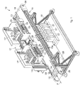
- forms of embodiment of the invention described here concern a printing apparatus 10 usable for printing on articles 12, such as for example articles 12 made of paper, cardboard, fabric, metal materials, plastic materials, glass or suchlike.
- the printing apparatus 10 can comprise two or more printing heads 17, a support structure 15 to which the printing heads 17 are associated and a feed device 13, disposed below the printing heads 17.
- the printing apparatus 10 can also comprise a support frame 16, configured to support at least the feed device 13 and the printing heads 17.
- the feed device 13 can include a belt 18, or mat, configured to selectively determine the movement of at least a support element 14 disposed on it, such as for example a plate or a tray, containing at least an article 12 to be printed.
- the movement of the belt 18 can occur, for example, in a direction F indicated by an arrow in the attached drawings.
- the belt 18 can be configured closed in a ring and stretched between at least two rollers 20, with axes of rotation parallel and substantially perpendicular to the direction F indicated by the arrow.
- At least one of the rollers 20 can be connected to a motor 21, for example the electric type, configured to selectively drive it and determine a rotation thereof around its axis, with consequent movement of the belt 18 in the direction F indicated by the arrow.
- the printing heads 17 can be disposed aligned in the direction of feed F defined by the movement of the belt 18, so as to carry out a process of sequential printing on the article 12.
- the printing apparatus 10 can comprise two printing heads 17' and 17", of which the first printing head 17' can be configured to carry out a first basic printing while the second printing head 17" can be configured to determine the finishing printing of the article 12.
- first and the second printing heads 17' and 17" can be connected to the same support structure 15.
- each printing head 17' and 17" can be connected to a respective support structure 15.
- connection between the support structure 15 and the printing heads 17' and 17" can be obtained, for example, through mechanical welding, or by using screws.
- the printing heads 17' and 17" can comprise at least a plurality of nozzles 23, configured to selectively release a printing material on the article 12.
- each printing head 17' and 17" can also comprise at least a drying unit 25, as for example a lamp with UV, LED or other source of energy, configured to selectively dry the printing material substantially instantaneously, guaranteeing it is fixed on the article 12.
- a drying unit 25 as for example a lamp with UV, LED or other source of energy, configured to selectively dry the printing material substantially instantaneously, guaranteeing it is fixed on the article 12.
- Each printing nozzle 23 can be selectively commanded, in a substantially known way, to deposit the printing material on the article 12 according to a prefixed pattern.
- the printing material can be of different types, such as for example, but not only, ink, paint, dye, or other types of material able to confer the desired enhancement on the article 12.
- the printing material can be configured to supply to the article 12, once fixed on it, specific surface characteristics, such as for example a shiny or opaque effect, or other characteristics perceptible to the touch, such as a smooth or rough effect, or again other graphical effects.
- each printing head 17 can comprise a different number of printing nozzles 23, depending on specific needs.
- the printing nozzles 23 can each release a different type of printing material, or all the same printing material, or again only some of them can release the same type of printing material different from that of the others.
- the printing nozzles 23 can be configured to release printing material of a specific color, chosen for example from white, black, magenta, yellow or cyan.
- the printing nozzles 23 can also be configured to release a combination of the colors cited above, depending on the specific characteristics of enhancement to be given to the article 12.
- the first printing unit 17' can comprise, for example, at least two printing nozzles 23 configured to release this type of printing material, in order to make the first coat on the article 12 to be printed.
- the printing material can be fed to the printing nozzles 23 by means of at least a pumping device, not shown in the attached drawings, configured to take the printing material from at least a corresponding tank 27.
- the printing apparatus 10 can comprise a plurality of tanks 27, located for example in a lower portion of the feed device 13, in order to reduce the bulk thereof.
- each of the tanks 27 can contain a specific printing material, different from that contained in the others, and can be selectively connected, for example through one or more pipes, to each of the printing nozzles 23 of the printing heads 17' and 17", configured to release that specific printing material ( fig. 1 ).
- the printing heads 17' and 17" can be selectively mobile vertically with respect to the work plane defined by the feed device 13.
- the printing heads 17' and 17" are lowered to take the printing nozzles 23 to the predetermined distance with respect to the articles 12 disposed on the belt 18, depending on their shape and size, so as to define the correct distance for delivering the printing material and to allow an optimal release of the printing material, for example in the form of drops, when the article 12 is located in correspondence to the printing heads 17' and 17".
- the printing heads 17' and 17" can move away from the belt 18 and return to a non-operating position.
- the printing apparatus 10 can also comprise a command and control unit, not shown in the attached drawings, configured at least to command the movement of the printing heads 17', 17" and determine their distance from the feed device 13.
- a command and control unit not shown in the attached drawings, configured at least to command the movement of the printing heads 17', 17" and determine their distance from the feed device 13.
- command and control unit can also be configured to detect the quantity and condition of the printing material sent to the printing nozzles 23.
- At least a level sensor can be connected to the command and control unit, configured to detect if in at least one of the tanks 27 the quantity of the printing material present is less than a pre-established value.
- the level sensors can be chosen from a group comprising, for example, optical sensors, magnetic sensors or floating sensors or suchlike.
- the feed device 13 can also comprise one or more guide elements 28, configured to correctly position the support element 14 on the belt 18 if it should be in a position not to allow high precision of the printing process, for example because of the vibrations produced by the movement of the belt 18.
- the guide elements 28 can also be configured mobile in a direction substantially orthogonal to the direction of feed of the belt 18, so as to be able to adapt to the support elements 14 with different sizes.
- the support element 14, containing one or more articles 12, in this case two articles 12, can be disposed manually or automatically on the feed device 13, selectively activated by the motor 21, for example by means of the command and control unit.
- the support element 14 can be made to advance in a continuous manner at a pre-fixed or adjustable speed, depending on the characteristics of the article 12 or the printing material.
- the feed device 13 can take the support element 14 into correspondence with the first printing head 17' ( fig. 1 ).
- the printing material can be deposited continuously, that is, while the article 12 is in movement because it is transported by the belt 18.
- the support material can be deposited by means of the selective lowering of the first printing head 17' toward the article 12.
- the first printing head 17' can determine the release onto the article 12 of at least a first layer of the printing material, for example comprising a base layer of white, and a graphical image formed by a combination of the primary colors, black, yellow, magenta or cyan, delivered by the respective printing nozzles 23.
- the support element 14 can be transported by the belt 18 in correspondence to the drying unit 25, carrying out the drying, again continuously, and as a consequence, the attachment of the printing material on the articles 12a.
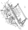
- the support element 14 is then made to advance to the second printing head 17" where, in the same way as described above, except for the delivery of white, the second printing cycle is carried out.
- a second tray 14 is positioned in correspondence to the first printing head 17', in order to carry out the first printing cycle, as seen in fig. 2 .
- drying unit 25 downstream of the second printing unit 17" that attaches the printing material on the article 12, determining the completion of the operation.
- the graphical design to be reproduced on the article 12 is particularly complex, it is possible to provide the presence of more than two printing heads 17, for example three or more, disposed aligned in the direction of feed of the belt 18, each of which can be configured to determine the depositing and attachment of at least one layer of printing material on the article 12.
Claims (8)
- Druckvorrichtung zum Drucken auf zumindest einem Artikel (12), umfassend zumindest zwei Druckköpfe, und zwar einen ersten (17') und einen zweiten Druckkopf (17"), die in einer Richtung (F) zueinander ausgerichtet angeordnet sind, und eine Zuführungseinrichtung (13), die dazu geeignet ist, den zu bedruckenden Artikel (12) entlang der Ausrichtungsrichtung der beiden Druckköpfe (17, 17', 17") zuzuführen, so dass der Artikel (12) sequentiell in Zusammenarbeit mit den beiden Druckköpfen (17, 17', 17") positioniert wird, worin
der erste Druckkopf (17') eine Vielzahl von Zuführdüsen (23) umfasst, die dafür ausgelegt sind, eine Hintergrundfarbe zu liefern, um eine Druckbasis zu bilden, um ein erstes Grunddrucken während eines ersten Druckzyklus durchzuführen;
der zweite Druckkopf (17") eine Vielzahl von Düsen (23) umfasst, die dafür ausgelegt sind, eine jeweilige Primärfarbe zur Bildung der Farbe während eines zweiten Druckzyklus zu liefern;
zumindest eine Trocknungsvorrichtung (25) zwischen dem ersten Druckkopf (17') und dem zweiten Druckkopf (17") angeordnet ist; und dadurch gekennzeichnet, dass die Zuführungseinrichtung (13) ein Band (18) ist, das dafür ausgelegt ist, die Bewegung von zumindest einem darauf angeordneten Abstützelement (14) selektiv zu bestimmen, wobei das Abstützelement zumindest einen zu bedruckenden Artikel enthält, wobei die Zuführungseinrichtung (13) ein oder mehrere Führungselemente (28) umfasst, die dafür ausgelegt sind, das Abstützelement (14) auf das Band (18) richtig zu positionieren. - Druckvorrichtung nach Anspruch 1, dadurch gekennzeichnet, dass der zweite Druckkopf (17"), stromabwärts der jeweiligen Zuführdüsen (23), eine weitere Trocknungsvorrichtung (25) umfasst, die dafür ausgelegt ist, die Farbe im Wesentlichen sofort am Ausgang aus dem jeweiligen Druckdurchgang zu trocknen.
- Druckvorrichtung nach einem der vorhergehenden Ansprüche, dadurch gekennzeichnet, dass auf dem Belt (18) die Artikel (18) sequentiell bei einem gegenseitigen Abstand positioniert sind, der dem Abstand zwischen den beiden Druckköpfen (17', 17") entspricht.
- Druckvorrichtung nach einem der vorhergehenden Ansprüche, dadurch gekennzeichnet, dass die beiden Druckköpfe (17', 17") auf einer gemeinsamen Abstützstruktur (15) montiert sind, die zumindest mit Mitteln versehen ist, die das gleichzeitige Absenken/Anheben der Druckköpfe (17', 17") in Bezug auf den in jenem Augenblick laufenden Druckschritt ermöglichen.
- Druckvorrichtung nach einem der vorhergehenden Ansprüche, dadurch gekennzeichnet, dass sie eine Steuerungs- und Überwachungseinheit umfasst, die dafür ausgelegt ist, die Bewegung der Druckköpfe (17', 17") zum Artikel (12) hin/vom Artikel (12) weg während des Druckprozesses zumindest selektiv zu steuern.
- Verfahren zum Drucken auf zumindest einem Artikel (12, 12a, 12b) durch eine Vorrichtung nach einem der Ansprüche 1 bis 5, dadurch gekennzeichnet, dass es vorsieht, den Artikel (12, 12a, 12b) kontinuierlich mittels eines Bandes (18) durch zumindest zwei Druckköpfe (17', 17") zu bewegen, um jeweils einen ersten Grunddruckvorgang und zumindest einen zweiten Fertigdruckvorgang durchzuführen, indem der Artikel (12, 12a, 12b) entlang der Druckköpfe (17', 17") in Bewegung gehalten wird.
- Druckverfahren nach Anspruch 6, dadurch gekennzeichnet, dass es vorsieht, einen im Wesentlichen sofortigen Trocknungszyklus am Ausgang aus jedem der Druckköpfe (17', 17") durchzuführen, wobei der Artikel (12, 12a, 12b) in Bewegung gehalten wird.
- Druckverfahren nach Anspruch 6 oder 7, dadurch gekennzeichnet, dass es vorsieht, dass zwei oder mehrere Artikel (12, 12a, 12b) auf dem Band (18) bei einem Abstand positioniert sind, der im Wesentlichen dem Abstand zwischen den Druckköpfen (17', 17") entspricht, so dass, wenn ein zweiter Artikel (12b) dem Fertigdrucken im zweiten Druckkopf (17") unterzogen wird, ein erster Artikel (12a) dem Grunddrucken im ersten Druckkopf (17') unterzogen wird.
Priority Applications (1)
| Application Number | Priority Date | Filing Date | Title |
|---|---|---|---|
| PL15168738T PL2946937T3 (pl) | 2014-05-21 | 2015-05-21 | Urządzenie drukujące i odpowiedni sposób |
Applications Claiming Priority (1)
| Application Number | Priority Date | Filing Date | Title |
|---|---|---|---|
| ITUD20140085 | 2014-05-21 |
Publications (2)
| Publication Number | Publication Date |
|---|---|
| EP2946937A1 EP2946937A1 (de) | 2015-11-25 |
| EP2946937B1 true EP2946937B1 (de) | 2020-02-12 |
Family
ID=51220816
Family Applications (1)
| Application Number | Title | Priority Date | Filing Date |
|---|---|---|---|
| EP15168738.1A Active EP2946937B1 (de) | 2014-05-21 | 2015-05-21 | Druckvorrichtung und zugehöriges verfahren |
Country Status (3)
| Country | Link |
|---|---|
| EP (1) | EP2946937B1 (de) |
| ES (1) | ES2776167T3 (de) |
| PL (1) | PL2946937T3 (de) |
Families Citing this family (3)
| Publication number | Priority date | Publication date | Assignee | Title |
|---|---|---|---|---|
| WO2018133976A1 (de) * | 2017-01-23 | 2018-07-26 | Koenig & Bauer Ag | Druckmaschine |
| CN107097535A (zh) * | 2017-06-14 | 2017-08-29 | 淮南泰隆机械制造有限公司 | 自动推移式锚具打码机 |
| ES2899329B2 (es) * | 2020-09-10 | 2023-02-02 | Gruppo Tecnoferrari Spa | Aparato de impresion digital para placas de vidrio y modulo de limpieza relacionado |
Family Cites Families (4)
| Publication number | Priority date | Publication date | Assignee | Title |
|---|---|---|---|---|
| DE602005004935T2 (de) * | 2005-12-22 | 2009-02-26 | Tapematic S.P.A. | Tintenstrahldruckapparat und Verfahren |
| US8353591B2 (en) * | 2006-04-20 | 2013-01-15 | Kabushiki Kaisha Isowa | Apparatus and method for printing corrugated cardboard sheets |
| DE102006034060B4 (de) * | 2006-07-20 | 2009-01-15 | Ball Packaging Europe Gmbh | Verfahren und Vorrichtung zum Dekorieren einer unebenen Fläche an einem formstabilen Objekt |
| JP5560658B2 (ja) * | 2009-10-28 | 2014-07-30 | セイコーエプソン株式会社 | 印刷装置 |
-
2015
- 2015-05-21 ES ES15168738T patent/ES2776167T3/es active Active
- 2015-05-21 PL PL15168738T patent/PL2946937T3/pl unknown
- 2015-05-21 EP EP15168738.1A patent/EP2946937B1/de active Active
Non-Patent Citations (1)
| Title |
|---|
| None * |
Also Published As
| Publication number | Publication date |
|---|---|
| ES2776167T3 (es) | 2020-07-29 |
| EP2946937A1 (de) | 2015-11-25 |
| PL2946937T3 (pl) | 2020-08-10 |
Similar Documents
| Publication | Publication Date | Title |
|---|---|---|
| JP4963869B2 (ja) | プレート状ワークの短辺部分に模様付けをする装置及び方法 | |
| US9096073B2 (en) | Device and method for printing, in particular for printing containers in several colors | |
| EP2946937B1 (de) | Druckvorrichtung und zugehöriges verfahren | |
| RU2009105881A (ru) | Способ и устройство для декорирования неровной поверхности предмета стабильной формы | |
| EP2326506B1 (de) | Digitaler tintenstrahldrucker und verfahren | |
| TWI628069B (zh) | 噴墨列印裝置及列印方法 | |
| CN104275922A (zh) | 容器印刷设备和方法 | |
| EP3098081B1 (de) | Gerät und verfahren zum digitalen drucken auf artikeln | |
| TR201802141T4 (tr) | Bir panelin dekore edilmesine yönelik bir yöntem ve bir aparat. | |
| CN107073992A (zh) | 数字印刷和装饰的制品 | |
| CN107148356A (zh) | 用于装饰制品的过程 | |
| JP5781473B2 (ja) | 加飾部品の製造装置及び製造方法 | |
| CZ20013308A3 (cs) | Proudová výroba tuhých předmětů | |
| JP2004500280A (ja) | パッケージングシステムの製造方法 | |
| US9895875B2 (en) | Printing unit having a plate cylinder and plate changer | |
| CN104520111A (zh) | 用于三维产品的装饰的机器 | |
| CN202319300U (zh) | 一种异形陶瓷釉下彩绘机 | |
| WO2024054224A1 (en) | Reconfigurable single media printer having a positionable media support carriage | |
| US11396191B1 (en) | Compact media decorator optimized for transparent and semi-transparent media | |
| CN102358081A (zh) | 一种异形陶瓷釉下彩绘机 | |
| EP4100257A1 (de) | Verfahren zur steuerung der bewegung von transparenten medien während der endaushärtung zur minimierung der druckkopfverschlechterung | |
| US10035160B2 (en) | Decoration line for ceramic products and process for decorating on ceramic products | |
| KR20200009729A (ko) | 원통체 입체 인쇄 장치 | |
| JP6672830B2 (ja) | 印刷装置および印刷方法 | |
| US20230128066A1 (en) | Reconfigurable Single Media Printer Having a Positionable Media Support Carriage |
Legal Events
| Date | Code | Title | Description |
|---|---|---|---|
| PUAI | Public reference made under article 153(3) epc to a published international application that has entered the european phase |
Free format text: ORIGINAL CODE: 0009012 |
|
| AK | Designated contracting states |
Kind code of ref document: A1 Designated state(s): AL AT BE BG CH CY CZ DE DK EE ES FI FR GB GR HR HU IE IS IT LI LT LU LV MC MK MT NL NO PL PT RO RS SE SI SK SM TR |
|
| AX | Request for extension of the european patent |
Extension state: BA ME |
|
| 17P | Request for examination filed |
Effective date: 20160908 |
|
| RBV | Designated contracting states (corrected) |
Designated state(s): AL AT BE BG CH CY CZ DE DK EE ES FI FR GB GR HR HU IE IS IT LI LT LU LV MC MK MT NL NO PL PT RO RS SE SI SK SM TR |
|
| STAA | Information on the status of an ep patent application or granted ep patent |
Free format text: STATUS: EXAMINATION IS IN PROGRESS |
|
| 17Q | First examination report despatched |
Effective date: 20190514 |
|
| GRAP | Despatch of communication of intention to grant a patent |
Free format text: ORIGINAL CODE: EPIDOSNIGR1 |
|
| STAA | Information on the status of an ep patent application or granted ep patent |
Free format text: STATUS: GRANT OF PATENT IS INTENDED |
|
| INTG | Intention to grant announced |
Effective date: 20191126 |
|
| GRAS | Grant fee paid |
Free format text: ORIGINAL CODE: EPIDOSNIGR3 |
|
| GRAA | (expected) grant |
Free format text: ORIGINAL CODE: 0009210 |
|
| STAA | Information on the status of an ep patent application or granted ep patent |
Free format text: STATUS: THE PATENT HAS BEEN GRANTED |
|
| AK | Designated contracting states |
Kind code of ref document: B1 Designated state(s): AL AT BE BG CH CY CZ DE DK EE ES FI FR GB GR HR HU IE IS IT LI LT LU LV MC MK MT NL NO PL PT RO RS SE SI SK SM TR |
|
| RAP1 | Party data changed (applicant data changed or rights of an application transferred) |
Owner name: JET-SET SRL |
|
| REG | Reference to a national code |
Ref country code: GB Ref legal event code: FG4D |
|
| REG | Reference to a national code |
Ref country code: CH Ref legal event code: EP |
|
| REG | Reference to a national code |
Ref country code: AT Ref legal event code: REF Ref document number: 1231589 Country of ref document: AT Kind code of ref document: T Effective date: 20200215 |
|
| REG | Reference to a national code |
Ref country code: IE Ref legal event code: FG4D |
|
| REG | Reference to a national code |
Ref country code: DE Ref legal event code: R096 Ref document number: 602015046659 Country of ref document: DE |
|
| REG | Reference to a national code |
Ref country code: CH Ref legal event code: NV Representative=s name: NOVAGRAAF INTERNATIONAL SA, CH |
|
| REG | Reference to a national code |
Ref country code: ES Ref legal event code: FG2A Ref document number: 2776167 Country of ref document: ES Kind code of ref document: T3 Effective date: 20200729 |
|
| PG25 | Lapsed in a contracting state [announced via postgrant information from national office to epo] |
Ref country code: NO Free format text: LAPSE BECAUSE OF FAILURE TO SUBMIT A TRANSLATION OF THE DESCRIPTION OR TO PAY THE FEE WITHIN THE PRESCRIBED TIME-LIMIT Effective date: 20200512 Ref country code: FI Free format text: LAPSE BECAUSE OF FAILURE TO SUBMIT A TRANSLATION OF THE DESCRIPTION OR TO PAY THE FEE WITHIN THE PRESCRIBED TIME-LIMIT Effective date: 20200212 Ref country code: RS Free format text: LAPSE BECAUSE OF FAILURE TO SUBMIT A TRANSLATION OF THE DESCRIPTION OR TO PAY THE FEE WITHIN THE PRESCRIBED TIME-LIMIT Effective date: 20200212 |
|
| REG | Reference to a national code |
Ref country code: LT Ref legal event code: MG4D |
|
| REG | Reference to a national code |
Ref country code: NL Ref legal event code: MP Effective date: 20200212 |
|
| PG25 | Lapsed in a contracting state [announced via postgrant information from national office to epo] |
Ref country code: HR Free format text: LAPSE BECAUSE OF FAILURE TO SUBMIT A TRANSLATION OF THE DESCRIPTION OR TO PAY THE FEE WITHIN THE PRESCRIBED TIME-LIMIT Effective date: 20200212 Ref country code: GR Free format text: LAPSE BECAUSE OF FAILURE TO SUBMIT A TRANSLATION OF THE DESCRIPTION OR TO PAY THE FEE WITHIN THE PRESCRIBED TIME-LIMIT Effective date: 20200513 Ref country code: IS Free format text: LAPSE BECAUSE OF FAILURE TO SUBMIT A TRANSLATION OF THE DESCRIPTION OR TO PAY THE FEE WITHIN THE PRESCRIBED TIME-LIMIT Effective date: 20200612 Ref country code: LV Free format text: LAPSE BECAUSE OF FAILURE TO SUBMIT A TRANSLATION OF THE DESCRIPTION OR TO PAY THE FEE WITHIN THE PRESCRIBED TIME-LIMIT Effective date: 20200212 Ref country code: BG Free format text: LAPSE BECAUSE OF FAILURE TO SUBMIT A TRANSLATION OF THE DESCRIPTION OR TO PAY THE FEE WITHIN THE PRESCRIBED TIME-LIMIT Effective date: 20200512 Ref country code: SE Free format text: LAPSE BECAUSE OF FAILURE TO SUBMIT A TRANSLATION OF THE DESCRIPTION OR TO PAY THE FEE WITHIN THE PRESCRIBED TIME-LIMIT Effective date: 20200212 |
|
| PG25 | Lapsed in a contracting state [announced via postgrant information from national office to epo] |
Ref country code: NL Free format text: LAPSE BECAUSE OF FAILURE TO SUBMIT A TRANSLATION OF THE DESCRIPTION OR TO PAY THE FEE WITHIN THE PRESCRIBED TIME-LIMIT Effective date: 20200212 |
|
| PG25 | Lapsed in a contracting state [announced via postgrant information from national office to epo] |
Ref country code: CZ Free format text: LAPSE BECAUSE OF FAILURE TO SUBMIT A TRANSLATION OF THE DESCRIPTION OR TO PAY THE FEE WITHIN THE PRESCRIBED TIME-LIMIT Effective date: 20200212 Ref country code: RO Free format text: LAPSE BECAUSE OF FAILURE TO SUBMIT A TRANSLATION OF THE DESCRIPTION OR TO PAY THE FEE WITHIN THE PRESCRIBED TIME-LIMIT Effective date: 20200212 Ref country code: LT Free format text: LAPSE BECAUSE OF FAILURE TO SUBMIT A TRANSLATION OF THE DESCRIPTION OR TO PAY THE FEE WITHIN THE PRESCRIBED TIME-LIMIT Effective date: 20200212 Ref country code: EE Free format text: LAPSE BECAUSE OF FAILURE TO SUBMIT A TRANSLATION OF THE DESCRIPTION OR TO PAY THE FEE WITHIN THE PRESCRIBED TIME-LIMIT Effective date: 20200212 Ref country code: PT Free format text: LAPSE BECAUSE OF FAILURE TO SUBMIT A TRANSLATION OF THE DESCRIPTION OR TO PAY THE FEE WITHIN THE PRESCRIBED TIME-LIMIT Effective date: 20200705 Ref country code: SM Free format text: LAPSE BECAUSE OF FAILURE TO SUBMIT A TRANSLATION OF THE DESCRIPTION OR TO PAY THE FEE WITHIN THE PRESCRIBED TIME-LIMIT Effective date: 20200212 Ref country code: DK Free format text: LAPSE BECAUSE OF FAILURE TO SUBMIT A TRANSLATION OF THE DESCRIPTION OR TO PAY THE FEE WITHIN THE PRESCRIBED TIME-LIMIT Effective date: 20200212 Ref country code: SK Free format text: LAPSE BECAUSE OF FAILURE TO SUBMIT A TRANSLATION OF THE DESCRIPTION OR TO PAY THE FEE WITHIN THE PRESCRIBED TIME-LIMIT Effective date: 20200212 |
|
| REG | Reference to a national code |
Ref country code: DE Ref legal event code: R097 Ref document number: 602015046659 Country of ref document: DE |
|
| REG | Reference to a national code |
Ref country code: AT Ref legal event code: MK05 Ref document number: 1231589 Country of ref document: AT Kind code of ref document: T Effective date: 20200212 |
|
| PLBE | No opposition filed within time limit |
Free format text: ORIGINAL CODE: 0009261 |
|
| STAA | Information on the status of an ep patent application or granted ep patent |
Free format text: STATUS: NO OPPOSITION FILED WITHIN TIME LIMIT |
|
| 26N | No opposition filed |
Effective date: 20201113 |
|
| PG25 | Lapsed in a contracting state [announced via postgrant information from national office to epo] |
Ref country code: AT Free format text: LAPSE BECAUSE OF FAILURE TO SUBMIT A TRANSLATION OF THE DESCRIPTION OR TO PAY THE FEE WITHIN THE PRESCRIBED TIME-LIMIT Effective date: 20200212 Ref country code: MC Free format text: LAPSE BECAUSE OF FAILURE TO SUBMIT A TRANSLATION OF THE DESCRIPTION OR TO PAY THE FEE WITHIN THE PRESCRIBED TIME-LIMIT Effective date: 20200212 |
|
| PG25 | Lapsed in a contracting state [announced via postgrant information from national office to epo] |
Ref country code: SI Free format text: LAPSE BECAUSE OF FAILURE TO SUBMIT A TRANSLATION OF THE DESCRIPTION OR TO PAY THE FEE WITHIN THE PRESCRIBED TIME-LIMIT Effective date: 20200212 |
|
| GBPC | Gb: european patent ceased through non-payment of renewal fee |
Effective date: 20200521 |
|
| PG25 | Lapsed in a contracting state [announced via postgrant information from national office to epo] |
Ref country code: LU Free format text: LAPSE BECAUSE OF NON-PAYMENT OF DUE FEES Effective date: 20200521 |
|
| PG25 | Lapsed in a contracting state [announced via postgrant information from national office to epo] |
Ref country code: IE Free format text: LAPSE BECAUSE OF NON-PAYMENT OF DUE FEES Effective date: 20200521 Ref country code: GB Free format text: LAPSE BECAUSE OF NON-PAYMENT OF DUE FEES Effective date: 20200521 |
|
| PG25 | Lapsed in a contracting state [announced via postgrant information from national office to epo] |
Ref country code: TR Free format text: LAPSE BECAUSE OF FAILURE TO SUBMIT A TRANSLATION OF THE DESCRIPTION OR TO PAY THE FEE WITHIN THE PRESCRIBED TIME-LIMIT Effective date: 20200212 Ref country code: MT Free format text: LAPSE BECAUSE OF FAILURE TO SUBMIT A TRANSLATION OF THE DESCRIPTION OR TO PAY THE FEE WITHIN THE PRESCRIBED TIME-LIMIT Effective date: 20200212 Ref country code: CY Free format text: LAPSE BECAUSE OF FAILURE TO SUBMIT A TRANSLATION OF THE DESCRIPTION OR TO PAY THE FEE WITHIN THE PRESCRIBED TIME-LIMIT Effective date: 20200212 |
|
| PG25 | Lapsed in a contracting state [announced via postgrant information from national office to epo] |
Ref country code: MK Free format text: LAPSE BECAUSE OF FAILURE TO SUBMIT A TRANSLATION OF THE DESCRIPTION OR TO PAY THE FEE WITHIN THE PRESCRIBED TIME-LIMIT Effective date: 20200212 Ref country code: AL Free format text: LAPSE BECAUSE OF FAILURE TO SUBMIT A TRANSLATION OF THE DESCRIPTION OR TO PAY THE FEE WITHIN THE PRESCRIBED TIME-LIMIT Effective date: 20200212 |
|
| PGFP | Annual fee paid to national office [announced via postgrant information from national office to epo] |
Ref country code: IT Payment date: 20220421 Year of fee payment: 8 Ref country code: FR Payment date: 20220421 Year of fee payment: 8 Ref country code: ES Payment date: 20220601 Year of fee payment: 8 Ref country code: DE Payment date: 20220420 Year of fee payment: 8 |
|
| PGFP | Annual fee paid to national office [announced via postgrant information from national office to epo] |
Ref country code: PL Payment date: 20220425 Year of fee payment: 8 Ref country code: CH Payment date: 20220420 Year of fee payment: 8 Ref country code: BE Payment date: 20220420 Year of fee payment: 8 |
|
| REG | Reference to a national code |
Ref country code: DE Ref legal event code: R119 Ref document number: 602015046659 Country of ref document: DE |
|
| REG | Reference to a national code |
Ref country code: CH Ref legal event code: PL |
|
| REG | Reference to a national code |
Ref country code: BE Ref legal event code: MM Effective date: 20230531 |
|
| PG25 | Lapsed in a contracting state [announced via postgrant information from national office to epo] |
Ref country code: LI Free format text: LAPSE BECAUSE OF NON-PAYMENT OF DUE FEES Effective date: 20230531 Ref country code: CH Free format text: LAPSE BECAUSE OF NON-PAYMENT OF DUE FEES Effective date: 20230531 |
|
| PG25 | Lapsed in a contracting state [announced via postgrant information from national office to epo] |
Ref country code: IT Free format text: LAPSE BECAUSE OF NON-PAYMENT OF DUE FEES Effective date: 20230521 Ref country code: DE Free format text: LAPSE BECAUSE OF NON-PAYMENT OF DUE FEES Effective date: 20231201 |