EP2946863A1 - Zerspanungswerkzeug - Google Patents
Zerspanungswerkzeug Download PDFInfo
- Publication number
- EP2946863A1 EP2946863A1 EP14001821.9A EP14001821A EP2946863A1 EP 2946863 A1 EP2946863 A1 EP 2946863A1 EP 14001821 A EP14001821 A EP 14001821A EP 2946863 A1 EP2946863 A1 EP 2946863A1
- Authority
- EP
- European Patent Office
- Prior art keywords
- cutting
- cutting edge
- tip
- angle
- tool
- Prior art date
- Legal status (The legal status is an assumption and is not a legal conclusion. Google has not performed a legal analysis and makes no representation as to the accuracy of the status listed.)
- Granted
Links
- 238000003801 milling Methods 0.000 description 8
- 238000003754 machining Methods 0.000 description 3
- 230000002093 peripheral effect Effects 0.000 description 3
- 230000002950 deficient Effects 0.000 description 2
- 241000985128 Cladium mariscus Species 0.000 description 1
- 238000013459 approach Methods 0.000 description 1
- 238000000227 grinding Methods 0.000 description 1
- 230000012447 hatching Effects 0.000 description 1
- 230000002028 premature Effects 0.000 description 1
- 230000003313 weakening effect Effects 0.000 description 1
Images

Classifications
-
- B—PERFORMING OPERATIONS; TRANSPORTING
- B23—MACHINE TOOLS; METAL-WORKING NOT OTHERWISE PROVIDED FOR
- B23C—MILLING
- B23C5/00—Milling-cutters
- B23C5/02—Milling-cutters characterised by the shape of the cutter
- B23C5/10—Shank-type cutters, i.e. with an integral shaft
-
- B—PERFORMING OPERATIONS; TRANSPORTING
- B23—MACHINE TOOLS; METAL-WORKING NOT OTHERWISE PROVIDED FOR
- B23B—TURNING; BORING
- B23B2251/00—Details of tools for drilling machines
- B23B2251/12—Cross sectional views of the cutting edges
- B23B2251/122—Bevelled cutting edges
-
- B—PERFORMING OPERATIONS; TRANSPORTING
- B23—MACHINE TOOLS; METAL-WORKING NOT OTHERWISE PROVIDED FOR
- B23C—MILLING
- B23C2210/00—Details of milling cutters
- B23C2210/04—Angles
- B23C2210/0407—Cutting angles
- B23C2210/0414—Cutting angles different
-
- B—PERFORMING OPERATIONS; TRANSPORTING
- B23—MACHINE TOOLS; METAL-WORKING NOT OTHERWISE PROVIDED FOR
- B23C—MILLING
- B23C2210/00—Details of milling cutters
- B23C2210/12—Cross section of the cutting edge
- B23C2210/123—Bevelled cutting edges
-
- B—PERFORMING OPERATIONS; TRANSPORTING
- B23—MACHINE TOOLS; METAL-WORKING NOT OTHERWISE PROVIDED FOR
- B23C—MILLING
- B23C2210/00—Details of milling cutters
- B23C2210/20—Number of cutting edges
- B23C2210/201—Number of cutting edges one
-
- B—PERFORMING OPERATIONS; TRANSPORTING
- B23—MACHINE TOOLS; METAL-WORKING NOT OTHERWISE PROVIDED FOR
- B23C—MILLING
- B23C2265/00—Details of general geometric configurations
- B23C2265/08—Conical
Definitions
- the invention relates to a cutting geometry of a cutting tool that has at least one cutting edge on the conical tip, in particular it relates to a single-cutting engraving cutter.
- FIG. 2 and Fig. 3 Similar conditions occur in an engraving cutter when proceeding along the cutting edge towards the tip. That's over Fig. 2 and Fig. 3 can be seen where the active part of the milling cutter is shown in side view or in front view. The direction of rotation is indicated by a pile. Even if the back of the milling cutter has been machined at an angle ⁇ and a part of the cone, s. If the surface F, is the vector of the effective velocity at the diameter ⁇ d in the plane of the back, and from that point to the top, the cutting is insufficient and the machining of the groove is deficient. However, a possible further increase in the angle ⁇ would lead to an inadmissible weakening of the cutting edge.
- the invention has for its object to design a cutting geometry of a cutting tool, in particular a one-cutting engraving cutter, which would abolish the mentioned disadvantages of the known tools of this type to a substantial degree.
- the stated object is achieved by a cutting tool with at least one cutting edge on a conical tip.
- the cutting edge is ground so that a clearance angle ⁇ along the cutting edge from the outer diameter toward the tip of the tool gradually becomes 0 ° to 90 °, a cutting angle ⁇ keeps the values in the range of 60 ° to 90 °, and ⁇ in the opposite direction: from -90 ° at the tip to a value between 0 ° and 30 ° at the outer diameter.
- the cutting edge remains substantially straight along the entire length.
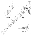
- a single-edged, tapered engraving cutter 4 and 5 has one, in its conical cutting part a ground specifically shaped end face 11.
- the cutter is clockwise. Its cutting edge 12 is ground in such a way as sections 1-1 to 7-7 on FIG. 7 show.
- a clearance angle ⁇ 1-7 of a spine 14 gradually changes its value from 0 ° to 90 ° along the cutting edge 12 such that a cutting angle ⁇ 1-7 retains its value of 90 ° while a rake angle ⁇ 1 - 7 in the opposite direction reaches values of - 90 ° at the top to a value between 0 ° and 30 ° at the outer diameter.
- the edge of the cutting edge 12 remains straight along the entire length.
- This cutting geometry takes into account the kinematics of milling in the engraving cutters and prevents the milling of the milling cutter, a defective machining of the workpiece and premature damage to the tool.
Landscapes
- Engineering & Computer Science (AREA)
- Mechanical Engineering (AREA)
- Milling Processes (AREA)
Abstract
Description
- Die Erfindung betrifft eine Schneidegeometrie eines Zerspanungswerkzeugs, dass zumindest eine Schneide an der kegeligen Spitze hat, insbesondere betrifft sie einen einschneidigen Gravierfräser.
- Kompakte einschneidige Fräser mit einer Drehzahl von 10.000 1/min. werden zum Schneiden von Zehntel Millimeter tiefen Rillen in metallischen Oberflächen benutzt. Die Fräser dieser Art haben eine an der kegeligen Spitze des Werkzeugs ausgeschliffene Schneide, wobei die Schneidkante an der Mantellinie des Kegels liegt. Der Spanwinkel bleibt die ganze Länge der Schneide entlang bei 0°. Konstant bleibt sowohl der Freiwinkel, der durch einen Schliff an der kegeligen Fläche des Rückens gebildet ist. Diese Schneidegeometrie im Bereich der Spitze des Fräsers bereitet Probleme, die durch eine Analogie mit einem Abstechmeißel zu erklären sind:
- Ein Eindringen eines Abstechmeißels in einen mit einer konstanten Geschwindigkeit drehenden Rundstab ist auf
Fig. 1 dargestellt. In diesem Ablaufschema werden Geschwindigkeiten und Winkel in den Punkten A und B angedeutet, wobei sich der Punkt C in der Achse des Rundstabs befindet. Es ist evident, dass sich bei konstanten Drehungen und konstanter Vorschubgeschwindigkeit der Wert und die Richtung des Vektors der effektiven Geschwindigkeit ändern, wobei dieser Vektor ve Summe des Vektors vc der Umfangsgeschwindigkeit und des Vektors vf der Vorschubgeschwindigkeit ist. Im Punkt B, der sich an dem kritischen Durchmesser ϕd krit befindet, liegt der Vektor ve der effektiven Geschwindigkeit bereits in der Ebene Aα des Rückens und der Abstechmeißel beginnt, sich mit dem Rücken an das Werkstück zu lehnen. Im Bereich des Punkts C nähert sich die Umfangsgeschwindigkeit der Null, und es kommt hier zu einer starken Interferenz des Rückens mit der bearbeitenden Umfangsfläche des Rundstücks, was zum Verreiben bzw. Bruch des Werkzeugs führen kann. Dies hat auch eine mangelhafte Bearbeitung der Stirnfläche im Bereich der Achse des Rundstücks und einen häufigen Bruch der Spitze des Wergzeugs zur Folge. - Ähnliche Verhältnisse treten bei einem Gravierfräser ein, wenn man entlang der Schneide Richtung Spitze vorgeht. Das ist aus
Fig. 2 und Fig. 3 ersichtlich, wo der aktive Teil des Fräsers in Seitenansicht bzw. in Frontansicht dargestellt ist. Die Drehrichtung wird durch einen Pfahl angegeben. Auch wenn der Rücken des Fräsers unter dem Winkel η hintergearbeitet und ein Teil des Kegels, s. Fläche F, abgenommen ist, so liegt der Vektor der effektiven Geschwindigkeit am Durchmesser ϕd in der Ebene des Rückens, und von dieser Stelle an bis zu der Spitze ist die Zerspanung unzureichend und die Bearbeitung der Rille mangelhaft. Eine eventuelle weitere Vergrößerung des Winkels η würde aber zu einer unzulässigen Schwächung der Schneide führen. - Der Erfindung liegt die Aufgabe zugrunde, eine Schneidegeometrie eines Zerspanungswerkzeugs, insbesondere eines einschneidigen Gravierfräsers zu entwerfen, die die angeführten Nachteile der bekannten Werkzeuge dieser Art in einem wesentlichen Maß abschaffen würde.
- Die gestellte Aufgabe wird erfindungsgemäß durch ein Zerspanungswerkzeug mit zumindest einer Schneide an einer kegeligen Spitze gelöst. Die Schneide ist so geschliffen, dass ein Freiwinkel α entlang der Schneide von dem äußeren Durchmesser aus Richtung Spitze des Werkzeugs allmählich einen Wert von 0° bis 90° annimmt, ein Schneidewinkel β die Werte im Bereich von 60° bis 90° behält und ein γ in der entgegengesetzten Richtung folgende Werte erreicht: von -90° an der Spitze bis zu einem Wert zwischen 0° und 30° am äußeren Durchmesser. Dabei bleibt die Schneidekante entlang der ganzen Länge im Wesentlichen geradlinig.
- Die Erfindung wird nachstehend anhand von einem in den Zeichnungen dargestellten Ausführungsbeispiel eines einschneidigen Gravierfräsers näher erläutert. Es zeigen:
- Fig. 1
- bis 3 Schemen, die zur Erläuterung des zu lösenden Problems dienen sollen,
- Fig. 4
- eine Seitenansicht eines Fräsers mit einer Detailansicht der Spitze,
- Fig. 5
- eine Frontansicht des Fräsers mit 7 zugeordneten senkrechten Schnitten 1-1 bis 7-7, die die Gestaltung der Schneide entlang ihrer Länge sichtbar machen.
- Fig. 6
- ist eine Ansicht der Spitze des Fräsers in Richtung der Achse des Werkzeugs, wobei die Neigung einzelner Flächen durch Schraffierung sichtbar gemacht ist.
- Ein einschneidiger kegeliger Gravierfräser nach
Fig. 4 und 5 hat eine, in seinem kegeligen Schneideteil eine geschliffene spezifisch geformte Stirnfläche 11. Der Fräser ist rechtslaufend. Seine Schneide 12 ist derart ausgeschliffen, wie die Schnitte 1-1 bis 7-7 auf Fig. 7 zeigen. Es ist ersichtlich, dass ein Freiwinkel α1-7 eines Rückens 14 seinen Wert von 0° bis zu 90° entlang der Schneide 12 allmählich ändert, dass ein Schneidewinkel β1-7 seinen Wert von 90° behält, während ein Spanwinkel γ 1 - 7 in der entgegengesetzten Richtung Werte von - 90° an der Spitze bis zu einem Wert zwischen 0° und 30° am äußeren Durchmesser erreicht. Die Kante der Schneide 12 bleibt entlang der ganzen Länge geradlinig. - Diese Schneidegeometrie berücksichtigt die Kinematik des Fräsens bei den Gravierfräsern und verhindert das Verreiben des Fräsers, eine mangelhafte Bearbeitung des Werkstücks und vorzeitige Beschädigung des Werkzeugs.
Claims (1)
- Zerspanungswerkzeug mit zumindest einer Schneide an einer kegeligen Spitze, dadurch gekennzeichnet, dass ein Freiwinkel (α) entlang der Schneide (12) von dem äußeren Durchmesser aus Richtung Spitze des Werkzeugs allmählich einen Wert von 0° bis 90° annimmt, ein Schneidewinkel (β) die Werte im Bereich von 60° bis 90° behält und ein Spanwinkel (γ) in der entgegengesetzten Richtung Werte von - 90° an der Spitze bis zu einem Wert zwischen 0° und 30° an dem äußeren Durchmesser erreicht, wobei die Schneidekante entlang der ganzen Länge im Wesentlichen geradlinig bleibt.
Priority Applications (1)
| Application Number | Priority Date | Filing Date | Title |
|---|---|---|---|
| EP14001821.9A EP2946863B1 (de) | 2014-05-23 | 2014-05-23 | Zerspanungswerkzeug |
Applications Claiming Priority (1)
| Application Number | Priority Date | Filing Date | Title |
|---|---|---|---|
| EP14001821.9A EP2946863B1 (de) | 2014-05-23 | 2014-05-23 | Zerspanungswerkzeug |
Publications (2)
| Publication Number | Publication Date |
|---|---|
| EP2946863A1 true EP2946863A1 (de) | 2015-11-25 |
| EP2946863B1 EP2946863B1 (de) | 2019-06-19 |
Family
ID=54325103
Family Applications (1)
| Application Number | Title | Priority Date | Filing Date |
|---|---|---|---|
| EP14001821.9A Active EP2946863B1 (de) | 2014-05-23 | 2014-05-23 | Zerspanungswerkzeug |
Country Status (1)
| Country | Link |
|---|---|
| EP (1) | EP2946863B1 (de) |
Citations (3)
| Publication number | Priority date | Publication date | Assignee | Title |
|---|---|---|---|---|
| DE102005003496A1 (de) * | 2005-01-25 | 2006-07-27 | Gühring, Jörg, Dr. | Variabler Schneidkantenabzug für Bohrwerkzeuge |
| US20110211922A1 (en) * | 2008-10-29 | 2011-09-01 | Sumitomo Electric Hardmetal Corp. | Ball end mill |
| US8021085B1 (en) * | 2007-02-23 | 2011-09-20 | Lance Nelson | Engraving tool with a very strong cutter tip to reduce breakage |
-
2014
- 2014-05-23 EP EP14001821.9A patent/EP2946863B1/de active Active
Patent Citations (3)
| Publication number | Priority date | Publication date | Assignee | Title |
|---|---|---|---|---|
| DE102005003496A1 (de) * | 2005-01-25 | 2006-07-27 | Gühring, Jörg, Dr. | Variabler Schneidkantenabzug für Bohrwerkzeuge |
| US8021085B1 (en) * | 2007-02-23 | 2011-09-20 | Lance Nelson | Engraving tool with a very strong cutter tip to reduce breakage |
| US20110211922A1 (en) * | 2008-10-29 | 2011-09-01 | Sumitomo Electric Hardmetal Corp. | Ball end mill |
Also Published As
| Publication number | Publication date |
|---|---|
| EP2946863B1 (de) | 2019-06-19 |
Similar Documents
| Publication | Publication Date | Title |
|---|---|---|
| WO2001091959A1 (de) | Bohrerspitze für einen spiralbohrer und verfahren zum herstellen einer spannut im bereich einer bohrerspitze für einen spiralbohrer | |
| DE2336598A1 (de) | Fraesmesser und fraesmesserkoerper | |
| DE3331553A1 (de) | Spanbrecheinsatz fuer metallschneidwerkzeuge | |
| DE2254270A1 (de) | Schneidplatte | |
| DE102013201062A1 (de) | Bohrspitze | |
| DE102015116623A1 (de) | Schaftfräser | |
| DE4405987C2 (de) | Schaftfräser | |
| DE3218953C2 (de) | Verfahren und Vorrichtung zur Ausbildung einer Schrägrille in einer Halbleitervorrichtung | |
| DE102013205363B4 (de) | Werkzeugkopf sowie Verfahren zur Bearbeitung eines metallischen Werkstücks | |
| EP3031560A1 (de) | Bearbeitungswerkzeug und schneidplatte für das bearbeitungswerkzeug | |
| EP2946863B1 (de) | Zerspanungswerkzeug | |
| WO2006079317A1 (de) | Variabler schneidkantenabzug für bohrwerkzeuge | |
| WO2019238287A1 (de) | Tieflochbohrer und bohrwerkzeug mit einer oder mehreren mulden in der spanfläche | |
| WO2008028462A1 (de) | Schruppfräser | |
| EP2915613B1 (de) | Querlochsenker | |
| DE202017101382U1 (de) | Fräswerkzeug | |
| EP2347844A1 (de) | Verfahren zum Nachbearbeiten einer Zentrierbohrung | |
| EP3507044B1 (de) | Einschneidiges fräswerkzeug | |
| DE2151804A1 (de) | Schaelmaschine mit umlaufendem messerkopf | |
| WO2014190363A1 (de) | Schneideinsatz aus hartmetall oder cermet für die drehbearbeitung | |
| DE1146330B (de) | Stirnmesserkopf fuer Verzahnungsmaschinen | |
| EP3150314B1 (de) | Schaftfräser | |
| EP3071356B1 (de) | Fräswerkzeug | |
| DE1627222C3 (de) | Werkzeug zur Feinbearbeitung von Bohrungen, insbesondere Reibahle | |
| DE4437542B4 (de) | Kegelaufbohrer |
Legal Events
| Date | Code | Title | Description |
|---|---|---|---|
| PUAI | Public reference made under article 153(3) epc to a published international application that has entered the european phase |
Free format text: ORIGINAL CODE: 0009012 |
|
| AK | Designated contracting states |
Kind code of ref document: A1 Designated state(s): AL AT BE BG CH CY CZ DE DK EE ES FI FR GB GR HR HU IE IS IT LI LT LU LV MC MK MT NL NO PL PT RO RS SE SI SK SM TR |
|
| AX | Request for extension of the european patent |
Extension state: BA ME |
|
| RBV | Designated contracting states (corrected) |
Designated state(s): AL AT BE BG CH CY CZ DE DK EE ES FI FR GB GR HR HU IE IS IT LI LT LU LV MC MK MT NL NO PL PT RO RS SE SI SK SM TR |
|
| 17P | Request for examination filed |
Effective date: 20151210 |
|
| GRAP | Despatch of communication of intention to grant a patent |
Free format text: ORIGINAL CODE: EPIDOSNIGR1 |
|
| STAA | Information on the status of an ep patent application or granted ep patent |
Free format text: STATUS: GRANT OF PATENT IS INTENDED |
|
| INTG | Intention to grant announced |
Effective date: 20190123 |
|
| GRAS | Grant fee paid |
Free format text: ORIGINAL CODE: EPIDOSNIGR3 |
|
| GRAA | (expected) grant |
Free format text: ORIGINAL CODE: 0009210 |
|
| STAA | Information on the status of an ep patent application or granted ep patent |
Free format text: STATUS: THE PATENT HAS BEEN GRANTED |
|
| AK | Designated contracting states |
Kind code of ref document: B1 Designated state(s): AL AT BE BG CH CY CZ DE DK EE ES FI FR GB GR HR HU IE IS IT LI LT LU LV MC MK MT NL NO PL PT RO RS SE SI SK SM TR |
|
| REG | Reference to a national code |
Ref country code: GB Ref legal event code: FG4D Free format text: NOT ENGLISH |
|
| REG | Reference to a national code |
Ref country code: CH Ref legal event code: EP |
|
| REG | Reference to a national code |
Ref country code: IE Ref legal event code: FG4D Free format text: LANGUAGE OF EP DOCUMENT: GERMAN |
|
| REG | Reference to a national code |
Ref country code: DE Ref legal event code: R096 Ref document number: 502014011965 Country of ref document: DE |
|
| REG | Reference to a national code |
Ref country code: AT Ref legal event code: REF Ref document number: 1144854 Country of ref document: AT Kind code of ref document: T Effective date: 20190715 |
|
| REG | Reference to a national code |
Ref country code: NL Ref legal event code: MP Effective date: 20190619 |
|
| PG25 | Lapsed in a contracting state [announced via postgrant information from national office to epo] |
Ref country code: HR Free format text: LAPSE BECAUSE OF FAILURE TO SUBMIT A TRANSLATION OF THE DESCRIPTION OR TO PAY THE FEE WITHIN THE PRESCRIBED TIME-LIMIT Effective date: 20190619 Ref country code: LT Free format text: LAPSE BECAUSE OF FAILURE TO SUBMIT A TRANSLATION OF THE DESCRIPTION OR TO PAY THE FEE WITHIN THE PRESCRIBED TIME-LIMIT Effective date: 20190619 Ref country code: AL Free format text: LAPSE BECAUSE OF FAILURE TO SUBMIT A TRANSLATION OF THE DESCRIPTION OR TO PAY THE FEE WITHIN THE PRESCRIBED TIME-LIMIT Effective date: 20190619 Ref country code: FI Free format text: LAPSE BECAUSE OF FAILURE TO SUBMIT A TRANSLATION OF THE DESCRIPTION OR TO PAY THE FEE WITHIN THE PRESCRIBED TIME-LIMIT Effective date: 20190619 Ref country code: SE Free format text: LAPSE BECAUSE OF FAILURE TO SUBMIT A TRANSLATION OF THE DESCRIPTION OR TO PAY THE FEE WITHIN THE PRESCRIBED TIME-LIMIT Effective date: 20190619 Ref country code: NO Free format text: LAPSE BECAUSE OF FAILURE TO SUBMIT A TRANSLATION OF THE DESCRIPTION OR TO PAY THE FEE WITHIN THE PRESCRIBED TIME-LIMIT Effective date: 20190919 |
|
| REG | Reference to a national code |
Ref country code: LT Ref legal event code: MG4D |
|
| PG25 | Lapsed in a contracting state [announced via postgrant information from national office to epo] |
Ref country code: RS Free format text: LAPSE BECAUSE OF FAILURE TO SUBMIT A TRANSLATION OF THE DESCRIPTION OR TO PAY THE FEE WITHIN THE PRESCRIBED TIME-LIMIT Effective date: 20190619 Ref country code: GR Free format text: LAPSE BECAUSE OF FAILURE TO SUBMIT A TRANSLATION OF THE DESCRIPTION OR TO PAY THE FEE WITHIN THE PRESCRIBED TIME-LIMIT Effective date: 20190920 Ref country code: BG Free format text: LAPSE BECAUSE OF FAILURE TO SUBMIT A TRANSLATION OF THE DESCRIPTION OR TO PAY THE FEE WITHIN THE PRESCRIBED TIME-LIMIT Effective date: 20190919 Ref country code: LV Free format text: LAPSE BECAUSE OF FAILURE TO SUBMIT A TRANSLATION OF THE DESCRIPTION OR TO PAY THE FEE WITHIN THE PRESCRIBED TIME-LIMIT Effective date: 20190619 |
|
| PG25 | Lapsed in a contracting state [announced via postgrant information from national office to epo] |
Ref country code: PT Free format text: LAPSE BECAUSE OF FAILURE TO SUBMIT A TRANSLATION OF THE DESCRIPTION OR TO PAY THE FEE WITHIN THE PRESCRIBED TIME-LIMIT Effective date: 20191021 Ref country code: EE Free format text: LAPSE BECAUSE OF FAILURE TO SUBMIT A TRANSLATION OF THE DESCRIPTION OR TO PAY THE FEE WITHIN THE PRESCRIBED TIME-LIMIT Effective date: 20190619 Ref country code: NL Free format text: LAPSE BECAUSE OF FAILURE TO SUBMIT A TRANSLATION OF THE DESCRIPTION OR TO PAY THE FEE WITHIN THE PRESCRIBED TIME-LIMIT Effective date: 20190619 Ref country code: SK Free format text: LAPSE BECAUSE OF FAILURE TO SUBMIT A TRANSLATION OF THE DESCRIPTION OR TO PAY THE FEE WITHIN THE PRESCRIBED TIME-LIMIT Effective date: 20190619 Ref country code: CZ Free format text: LAPSE BECAUSE OF FAILURE TO SUBMIT A TRANSLATION OF THE DESCRIPTION OR TO PAY THE FEE WITHIN THE PRESCRIBED TIME-LIMIT Effective date: 20190619 Ref country code: RO Free format text: LAPSE BECAUSE OF FAILURE TO SUBMIT A TRANSLATION OF THE DESCRIPTION OR TO PAY THE FEE WITHIN THE PRESCRIBED TIME-LIMIT Effective date: 20190619 |
|
| PG25 | Lapsed in a contracting state [announced via postgrant information from national office to epo] |
Ref country code: IS Free format text: LAPSE BECAUSE OF FAILURE TO SUBMIT A TRANSLATION OF THE DESCRIPTION OR TO PAY THE FEE WITHIN THE PRESCRIBED TIME-LIMIT Effective date: 20191019 Ref country code: SM Free format text: LAPSE BECAUSE OF FAILURE TO SUBMIT A TRANSLATION OF THE DESCRIPTION OR TO PAY THE FEE WITHIN THE PRESCRIBED TIME-LIMIT Effective date: 20190619 Ref country code: IT Free format text: LAPSE BECAUSE OF FAILURE TO SUBMIT A TRANSLATION OF THE DESCRIPTION OR TO PAY THE FEE WITHIN THE PRESCRIBED TIME-LIMIT Effective date: 20190619 Ref country code: ES Free format text: LAPSE BECAUSE OF FAILURE TO SUBMIT A TRANSLATION OF THE DESCRIPTION OR TO PAY THE FEE WITHIN THE PRESCRIBED TIME-LIMIT Effective date: 20190619 |
|
| PG25 | Lapsed in a contracting state [announced via postgrant information from national office to epo] |
Ref country code: TR Free format text: LAPSE BECAUSE OF FAILURE TO SUBMIT A TRANSLATION OF THE DESCRIPTION OR TO PAY THE FEE WITHIN THE PRESCRIBED TIME-LIMIT Effective date: 20190619 |
|
| PG25 | Lapsed in a contracting state [announced via postgrant information from national office to epo] |
Ref country code: DK Free format text: LAPSE BECAUSE OF FAILURE TO SUBMIT A TRANSLATION OF THE DESCRIPTION OR TO PAY THE FEE WITHIN THE PRESCRIBED TIME-LIMIT Effective date: 20190619 Ref country code: PL Free format text: LAPSE BECAUSE OF FAILURE TO SUBMIT A TRANSLATION OF THE DESCRIPTION OR TO PAY THE FEE WITHIN THE PRESCRIBED TIME-LIMIT Effective date: 20190619 |
|
| PG25 | Lapsed in a contracting state [announced via postgrant information from national office to epo] |
Ref country code: IS Free format text: LAPSE BECAUSE OF FAILURE TO SUBMIT A TRANSLATION OF THE DESCRIPTION OR TO PAY THE FEE WITHIN THE PRESCRIBED TIME-LIMIT Effective date: 20200224 |
|
| REG | Reference to a national code |
Ref country code: DE Ref legal event code: R097 Ref document number: 502014011965 Country of ref document: DE |
|
| PLBE | No opposition filed within time limit |
Free format text: ORIGINAL CODE: 0009261 |
|
| STAA | Information on the status of an ep patent application or granted ep patent |
Free format text: STATUS: NO OPPOSITION FILED WITHIN TIME LIMIT |
|
| PG2D | Information on lapse in contracting state deleted |
Ref country code: IS |
|
| PGFP | Annual fee paid to national office [announced via postgrant information from national office to epo] |
Ref country code: DE Payment date: 20200525 Year of fee payment: 7 Ref country code: FR Payment date: 20200519 Year of fee payment: 7 |
|
| 26N | No opposition filed |
Effective date: 20200603 |
|
| PG25 | Lapsed in a contracting state [announced via postgrant information from national office to epo] |
Ref country code: SI Free format text: LAPSE BECAUSE OF FAILURE TO SUBMIT A TRANSLATION OF THE DESCRIPTION OR TO PAY THE FEE WITHIN THE PRESCRIBED TIME-LIMIT Effective date: 20190619 |
|
| PGFP | Annual fee paid to national office [announced via postgrant information from national office to epo] |
Ref country code: GB Payment date: 20200522 Year of fee payment: 7 |
|
| PG25 | Lapsed in a contracting state [announced via postgrant information from national office to epo] |
Ref country code: LI Free format text: LAPSE BECAUSE OF NON-PAYMENT OF DUE FEES Effective date: 20200531 Ref country code: CH Free format text: LAPSE BECAUSE OF NON-PAYMENT OF DUE FEES Effective date: 20200531 Ref country code: MC Free format text: LAPSE BECAUSE OF FAILURE TO SUBMIT A TRANSLATION OF THE DESCRIPTION OR TO PAY THE FEE WITHIN THE PRESCRIBED TIME-LIMIT Effective date: 20190619 |
|
| REG | Reference to a national code |
Ref country code: BE Ref legal event code: MM Effective date: 20200531 |
|
| PG25 | Lapsed in a contracting state [announced via postgrant information from national office to epo] |
Ref country code: LU Free format text: LAPSE BECAUSE OF NON-PAYMENT OF DUE FEES Effective date: 20200523 |
|
| PG25 | Lapsed in a contracting state [announced via postgrant information from national office to epo] |
Ref country code: IE Free format text: LAPSE BECAUSE OF NON-PAYMENT OF DUE FEES Effective date: 20200523 |
|
| PG25 | Lapsed in a contracting state [announced via postgrant information from national office to epo] |
Ref country code: BE Free format text: LAPSE BECAUSE OF NON-PAYMENT OF DUE FEES Effective date: 20200531 |
|
| REG | Reference to a national code |
Ref country code: AT Ref legal event code: MM01 Ref document number: 1144854 Country of ref document: AT Kind code of ref document: T Effective date: 20200523 |
|
| PG25 | Lapsed in a contracting state [announced via postgrant information from national office to epo] |
Ref country code: AT Free format text: LAPSE BECAUSE OF NON-PAYMENT OF DUE FEES Effective date: 20200523 |
|
| REG | Reference to a national code |
Ref country code: DE Ref legal event code: R119 Ref document number: 502014011965 Country of ref document: DE |
|
| GBPC | Gb: european patent ceased through non-payment of renewal fee |
Effective date: 20210523 |
|
| PG25 | Lapsed in a contracting state [announced via postgrant information from national office to epo] |
Ref country code: GB Free format text: LAPSE BECAUSE OF NON-PAYMENT OF DUE FEES Effective date: 20210523 Ref country code: DE Free format text: LAPSE BECAUSE OF NON-PAYMENT OF DUE FEES Effective date: 20211201 |
|
| PG25 | Lapsed in a contracting state [announced via postgrant information from national office to epo] |
Ref country code: MT Free format text: LAPSE BECAUSE OF FAILURE TO SUBMIT A TRANSLATION OF THE DESCRIPTION OR TO PAY THE FEE WITHIN THE PRESCRIBED TIME-LIMIT Effective date: 20190619 Ref country code: FR Free format text: LAPSE BECAUSE OF NON-PAYMENT OF DUE FEES Effective date: 20210531 Ref country code: CY Free format text: LAPSE BECAUSE OF FAILURE TO SUBMIT A TRANSLATION OF THE DESCRIPTION OR TO PAY THE FEE WITHIN THE PRESCRIBED TIME-LIMIT Effective date: 20190619 |
|
| PG25 | Lapsed in a contracting state [announced via postgrant information from national office to epo] |
Ref country code: MK Free format text: LAPSE BECAUSE OF FAILURE TO SUBMIT A TRANSLATION OF THE DESCRIPTION OR TO PAY THE FEE WITHIN THE PRESCRIBED TIME-LIMIT Effective date: 20190619 |