EP2946510B1 - Interpolationsbasierte kanalzustandsinformationserweiterungen in einer langfristigen evolution (lte) - Google Patents
Interpolationsbasierte kanalzustandsinformationserweiterungen in einer langfristigen evolution (lte) Download PDFInfo
- Publication number
- EP2946510B1 EP2946510B1 EP14703985.3A EP14703985A EP2946510B1 EP 2946510 B1 EP2946510 B1 EP 2946510B1 EP 14703985 A EP14703985 A EP 14703985A EP 2946510 B1 EP2946510 B1 EP 2946510B1
- Authority
- EP
- European Patent Office
- Prior art keywords
- channel
- frequency
- feedback
- frequency locations
- enb
- Prior art date
- Legal status (The legal status is an assumption and is not a legal conclusion. Google has not performed a legal analysis and makes no representation as to the accuracy of the status listed.)
- Active
Links
- 230000007774 longterm Effects 0.000 title description 8
- 230000005540 biological transmission Effects 0.000 claims description 57
- 238000000034 method Methods 0.000 claims description 39
- 238000004891 communication Methods 0.000 claims description 27
- 238000001914 filtration Methods 0.000 claims description 13
- 239000011159 matrix material Substances 0.000 claims description 12
- 230000011664 signaling Effects 0.000 claims description 8
- 238000004590 computer program Methods 0.000 claims description 2
- 235000019580 granularity Nutrition 0.000 description 19
- 239000013598 vector Substances 0.000 description 11
- 238000013461 design Methods 0.000 description 8
- 238000005516 engineering process Methods 0.000 description 8
- 230000008569 process Effects 0.000 description 8
- 238000012935 Averaging Methods 0.000 description 7
- 230000015654 memory Effects 0.000 description 6
- 238000005259 measurement Methods 0.000 description 5
- 101150071746 Pbsn gene Proteins 0.000 description 4
- 238000010586 diagram Methods 0.000 description 4
- 230000006870 function Effects 0.000 description 4
- 230000001413 cellular effect Effects 0.000 description 3
- 230000008859 change Effects 0.000 description 3
- 125000004122 cyclic group Chemical group 0.000 description 3
- 230000001419 dependent effect Effects 0.000 description 3
- 230000037230 mobility Effects 0.000 description 3
- 230000003287 optical effect Effects 0.000 description 3
- 230000001360 synchronised effect Effects 0.000 description 3
- 238000013459 approach Methods 0.000 description 2
- 230000008901 benefit Effects 0.000 description 2
- 230000001427 coherent effect Effects 0.000 description 2
- 230000001143 conditioned effect Effects 0.000 description 2
- 238000001514 detection method Methods 0.000 description 2
- 239000000835 fiber Substances 0.000 description 2
- 230000002452 interceptive effect Effects 0.000 description 2
- 230000008520 organization Effects 0.000 description 2
- 239000002245 particle Substances 0.000 description 2
- 230000000737 periodic effect Effects 0.000 description 2
- 238000012545 processing Methods 0.000 description 2
- 238000013139 quantization Methods 0.000 description 2
- 230000003044 adaptive effect Effects 0.000 description 1
- 230000009286 beneficial effect Effects 0.000 description 1
- 238000000354 decomposition reaction Methods 0.000 description 1
- 238000011156 evaluation Methods 0.000 description 1
- 238000005562 fading Methods 0.000 description 1
- 238000010295 mobile communication Methods 0.000 description 1
- 238000012986 modification Methods 0.000 description 1
- 230000004048 modification Effects 0.000 description 1
- 238000005457 optimization Methods 0.000 description 1
- 238000005192 partition Methods 0.000 description 1
- 230000009467 reduction Effects 0.000 description 1
- 238000013468 resource allocation Methods 0.000 description 1
- 230000002441 reversible effect Effects 0.000 description 1
- 230000003068 static effect Effects 0.000 description 1
- 238000012546 transfer Methods 0.000 description 1
- 238000011144 upstream manufacturing Methods 0.000 description 1
Images


Classifications
-
- H—ELECTRICITY
- H04—ELECTRIC COMMUNICATION TECHNIQUE
- H04W—WIRELESS COMMUNICATION NETWORKS
- H04W24/00—Supervisory, monitoring or testing arrangements
- H04W24/10—Scheduling measurement reports ; Arrangements for measurement reports
-
- H—ELECTRICITY
- H04—ELECTRIC COMMUNICATION TECHNIQUE
- H04B—TRANSMISSION
- H04B7/00—Radio transmission systems, i.e. using radiation field
- H04B7/02—Diversity systems; Multi-antenna system, i.e. transmission or reception using multiple antennas
- H04B7/022—Site diversity; Macro-diversity
- H04B7/024—Co-operative use of antennas of several sites, e.g. in co-ordinated multipoint or co-operative multiple-input multiple-output [MIMO] systems
-
- H—ELECTRICITY
- H04—ELECTRIC COMMUNICATION TECHNIQUE
- H04B—TRANSMISSION
- H04B7/00—Radio transmission systems, i.e. using radiation field
- H04B7/02—Diversity systems; Multi-antenna system, i.e. transmission or reception using multiple antennas
- H04B7/04—Diversity systems; Multi-antenna system, i.e. transmission or reception using multiple antennas using two or more spaced independent antennas
- H04B7/06—Diversity systems; Multi-antenna system, i.e. transmission or reception using multiple antennas using two or more spaced independent antennas at the transmitting station
- H04B7/0613—Diversity systems; Multi-antenna system, i.e. transmission or reception using multiple antennas using two or more spaced independent antennas at the transmitting station using simultaneous transmission
- H04B7/0615—Diversity systems; Multi-antenna system, i.e. transmission or reception using multiple antennas using two or more spaced independent antennas at the transmitting station using simultaneous transmission of weighted versions of same signal
- H04B7/0619—Diversity systems; Multi-antenna system, i.e. transmission or reception using multiple antennas using two or more spaced independent antennas at the transmitting station using simultaneous transmission of weighted versions of same signal using feedback from receiving side
- H04B7/0658—Feedback reduction
- H04B7/066—Combined feedback for a number of channels, e.g. over several subcarriers like in orthogonal frequency division multiplexing [OFDM]
-
- H—ELECTRICITY
- H04—ELECTRIC COMMUNICATION TECHNIQUE
- H04L—TRANSMISSION OF DIGITAL INFORMATION, e.g. TELEGRAPHIC COMMUNICATION
- H04L1/00—Arrangements for detecting or preventing errors in the information received
- H04L1/0001—Systems modifying transmission characteristics according to link quality, e.g. power backoff
- H04L1/0023—Systems modifying transmission characteristics according to link quality, e.g. power backoff characterised by the signalling
-
- H—ELECTRICITY
- H04—ELECTRIC COMMUNICATION TECHNIQUE
- H04B—TRANSMISSION
- H04B7/00—Radio transmission systems, i.e. using radiation field
- H04B7/02—Diversity systems; Multi-antenna system, i.e. transmission or reception using multiple antennas
- H04B7/04—Diversity systems; Multi-antenna system, i.e. transmission or reception using multiple antennas using two or more spaced independent antennas
- H04B7/0413—MIMO systems
- H04B7/0417—Feedback systems
-
- H—ELECTRICITY
- H04—ELECTRIC COMMUNICATION TECHNIQUE
- H04B—TRANSMISSION
- H04B7/00—Radio transmission systems, i.e. using radiation field
- H04B7/02—Diversity systems; Multi-antenna system, i.e. transmission or reception using multiple antennas
- H04B7/04—Diversity systems; Multi-antenna system, i.e. transmission or reception using multiple antennas using two or more spaced independent antennas
- H04B7/06—Diversity systems; Multi-antenna system, i.e. transmission or reception using multiple antennas using two or more spaced independent antennas at the transmitting station
- H04B7/0613—Diversity systems; Multi-antenna system, i.e. transmission or reception using multiple antennas using two or more spaced independent antennas at the transmitting station using simultaneous transmission
- H04B7/0615—Diversity systems; Multi-antenna system, i.e. transmission or reception using multiple antennas using two or more spaced independent antennas at the transmitting station using simultaneous transmission of weighted versions of same signal
- H04B7/0619—Diversity systems; Multi-antenna system, i.e. transmission or reception using multiple antennas using two or more spaced independent antennas at the transmitting station using simultaneous transmission of weighted versions of same signal using feedback from receiving side
- H04B7/0636—Feedback format
- H04B7/0639—Using selective indices, e.g. of a codebook, e.g. pre-distortion matrix index [PMI] or for beam selection
-
- H—ELECTRICITY
- H04—ELECTRIC COMMUNICATION TECHNIQUE
- H04L—TRANSMISSION OF DIGITAL INFORMATION, e.g. TELEGRAPHIC COMMUNICATION
- H04L1/00—Arrangements for detecting or preventing errors in the information received
- H04L1/0001—Systems modifying transmission characteristics according to link quality, e.g. power backoff
- H04L1/0023—Systems modifying transmission characteristics according to link quality, e.g. power backoff characterised by the signalling
- H04L1/0026—Transmission of channel quality indication
-
- H—ELECTRICITY
- H04—ELECTRIC COMMUNICATION TECHNIQUE
- H04L—TRANSMISSION OF DIGITAL INFORMATION, e.g. TELEGRAPHIC COMMUNICATION
- H04L1/00—Arrangements for detecting or preventing errors in the information received
- H04L1/0001—Systems modifying transmission characteristics according to link quality, e.g. power backoff
- H04L1/0023—Systems modifying transmission characteristics according to link quality, e.g. power backoff characterised by the signalling
- H04L1/0032—Without explicit signalling
-
- H—ELECTRICITY
- H04—ELECTRIC COMMUNICATION TECHNIQUE
- H04L—TRANSMISSION OF DIGITAL INFORMATION, e.g. TELEGRAPHIC COMMUNICATION
- H04L5/00—Arrangements affording multiple use of the transmission path
- H04L5/0091—Signaling for the administration of the divided path
Definitions
- Certain aspects of the disclosure generally relate to wireless communications and, more particularly, to techniques for interpolation-based channel state information (CSI) enhancements in long-term evolution (LTE).
- CSI channel state information
- Wireless communication networks are widely deployed to provide various communication services such as voice, video, packet data, messaging, broadcast, etc. These wireless networks may be multiple-access networks capable of supporting multiple users by sharing the available network resources. Examples of such multiple-access networks include Code Division Multiple Access (CDMA) networks, Time Division Multiple Access (TDMA) networks, Frequency Division Multiple Access (FDMA) networks, Orthogonal FDMA (OFDMA) networks and Single-Carrier FDMA (SC-FDMA) networks.
- CDMA Code Division Multiple Access
- TDMA Time Division Multiple Access
- FDMA Frequency Division Multiple Access
- OFDMA Orthogonal FDMA
- SC-FDMA Single-Carrier FDMA
- a wireless communication network may include a number of base stations that can support communication for a number of user equipments (UEs).
- UE user equipments
- a UE may communicate with a base station via the downlink and uplink.
- the downlink (or forward link) refers to the communication link from the base station to the UE
- the uplink (or reverse link) refers to the communication link from the UE to the base station.
- a base station may transmit data and control information on the downlink to a UE and/or may receive data and control information on the uplink from the UE.
- a transmission from the base station may observe interference due to transmissions from neighbor base stations.
- a transmission from the UE may cause interference to transmissions from other UEs communicating with the neighbor base stations. The interference may degrade performance on both the downlink and uplink.
- eNB could not directly obtain the corresponding CQI for CoMP or even traditional single point CQI, but would need to derive an approximate value based on such modified per-point CQI.
- Observation 3 The gain provided by additional inter-point phase is marginal when aggregated CQI is reported.
- Observation 4 The CSI feedback overhead is quite large for CoMP which puts a big burden on PUCCH and PUSCH. Based above observations, the authors propose as follows: Proposal 1: Additional RI could be configured to optimize CoMP gain or reduce the feedback overhead.
- Proposal 2 The CQI definition in Rel-8 should be reused as much as possible. Additional aggregated CQI could be reported with particular transmission hypothesis to further improve the CoMP performance.
- Proposal 3 Additional inter-point phase feedback could be put in a lower priority if studied in Rel-11.
- Proposal 4 The reporting set could be a subset of measurement set to reduce the UE complexity and feedback overhead.
- Proposal 5 The granularity of multiple transmitting points could be designed separately.
- Certain aspects provide a method for wireless communications by a user equipment (UE), as defined in claim 1.
- UE user equipment
- Certain aspects provide an apparatus for wireless communications by a UE, as defined in claim 9.
- a CDMA network may implement a radio technology such as Universal Terrestrial Radio Access (UTRA), cdma2000, etc.
- UTRA includes Wideband CDMA (WCDMA) and other variants of CDMA.
- cdma2000 covers IS-2000, IS-95 and IS-856 standards.
- a TDMA network may implement a radio technology such as Global System for Mobile Communications (GSM).
- GSM Global System for Mobile Communications
- An OFDMA network may implement a radio technology such as Evolved UTRA (E-UTRA), Ultra Mobile Broadband (UMB), IEEE 802.11 (Wi-Fi), IEEE 802.16 (WiMAX), IEEE 802.20, Flash-OFDM ® , etc.
- E-UTRA Evolved UTRA
- UMB Ultra Mobile Broadband
- IEEE 802.11 Wi-Fi
- WiMAX IEEE 802.16
- IEEE 802.20 Flash-OFDM ®
- UTRA and E-UTRA are part of Universal Mobile Telecommunication System (UMTS).
- 3GPP Long Term Evolution (LTE) and LTE-Advanced (LTE-A) are new releases of UMTS that use E-UTRA.
- UTRA, E-UTRA, UMTS, LTE, LTE-A and GSM are described in documents from an organization named "3rd Generation Partnership Project" (3GPP).
- cdma2000 and UMB are described in documents from an organization named "3rd Generation Partnership Project 2" (3GPP2).
- 3GPP2 3rd Generation Partnership Project 2
- the techniques described herein may be used for the wireless networks and radio technologies mentioned above as well as other wireless networks and radio technologies. For clarity, certain aspects of the techniques are described below for LTE, and LTE terminology is used in much of the description below.
- FIG. 1 shows a wireless communication network 100, which may be an LTE network.
- the wireless network 100 may include a number of evolved Node Bs (eNBs) 110 and other network entities.
- An eNB may be a station that communicates with user equipment devices (UEs) and may also be referred to as a base station, a Node B, an access point, etc.
- Each eNB 110 may provide communication coverage for a particular geographic area.
- the term "cell" can refer to a coverage area of an eNB and/or an eNB subsystem serving this coverage area, depending on the context in which the term is used.
- An eNB may provide communication coverage for a macro cell, a pico cell, a femto cell, and/or other types of cell.
- a macro cell may cover a relatively large geographic area (e.g., several kilometers in radius) and may allow unrestricted access by UEs with service subscription.
- a pico cell may cover a relatively small geographic area and may allow unrestricted access by UEs with service subscription.
- a femto cell may cover a relatively small geographic area (e.g., a home) and may allow restricted access by UEs having association with the femto cell (e.g., UEs in a Closed Subscriber Group (CSG), UEs for users in the home, etc.).
- CSG Closed Subscriber Group
- An eNB for a macro cell may be referred to as a macro eNB (i.e., a macro base station).
- An eNB for a pico cell may be referred to as a pico eNB (i.e., a pico base station).
- An eNB for a femto cell may be referred to as a femto eNB (i.e., a femto base station) or a home eNB.
- eNBs 110a, 110b, and 110c may be macro eNBs for macro cells 102a, 102b, and 102c, respectively.
- eNB 110x may be a pico eNB for a pico cell 102x.
- eNBs 110y and 110z may be femto eNBs for femto cells 102y and 102z, respectively.
- An eNB may support one or multiple (e.g., three) cells.
- the wireless network 100 may also include relay stations.
- a relay station is a station that receives a transmission of data and/or other information from an upstream station (e.g., an eNB or a UE) and sends a transmission of the data and/or other information to a downstream station (e.g., a UE or an eNB).
- a relay station may also be a UE that relays transmissions for other UEs.
- a relay station 110r may communicate with eNB 110a and a UE 120r in order to facilitate communication between eNB 110a and UE 120r.
- a relay station may also be referred to as a relay eNB, a relay, etc.
- the wireless network 100 may be a heterogeneous network (HetNet) that includes eNBs of different types, e.g., macro eNBs, pico eNBs, femto eNBs, relays, etc. These different types of eNBs may have different transmit power levels, different coverage areas, and different impact on interference in the wireless network 100.
- HetNet HetNet
- macro eNBs may have a high transmit power level (e.g., 20 watts) whereas pico eNBs, femto eNBs, and relays may have a lower transmit power level (e.g., 1 watt).
- the wireless network 100 may support synchronous or asynchronous operation.
- the eNBs may have similar frame timing, and transmissions from different eNBs may be approximately aligned in time.
- the eNBs may have different frame timing, and transmissions from different eNBs may not be aligned in time.
- the techniques described herein may be used for both synchronous and asynchronous operation.
- a network controller 130 may couple to a set of eNBs and provide coordination and control for these eNBs.
- the network controller 130 may communicate with eNBs 110 via a backhaul.
- the eNBs 110 may also communicate with one another, e.g., directly or indirectly via wireless or wireline backhaul.
- the UEs 120 may be dispersed throughout the wireless network 100, and each UE may be stationary or mobile.
- a UE may also be referred to as a terminal, a mobile station, a subscriber unit, a station, etc.
- a UE may be a cellular phone, a personal digital assistant (PDA), a wireless modem, a wireless communication device, a handheld device, a laptop computer, a cordless phone, a wireless local loop (WLL) station, a tablet, etc.
- PDA personal digital assistant
- WLL wireless local loop
- a UE may be able to communicate with macro eNBs, pico eNBs, femto eNBs, relays, etc.
- a solid line with double arrows indicates desired transmissions between a UE and a serving eNB, which is an eNB designated to serve the UE on the downlink and/or uplink.
- a dashed line with double arrows indicates interfering transmissions between a UE and an eNB.
- the UE may comprise an LTE Release 10 UE.
- LTE utilizes orthogonal frequency division multiplexing (OFDM) on the downlink and single-carrier frequency division multiplexing (SC-FDM) on the uplink.
- OFDM and SC-FDM partition the system bandwidth into multiple (K) orthogonal subcarriers, which are also commonly referred to as tones, bins, etc.
- K orthogonal subcarriers
- Each subcarrier may be modulated with data.
- modulation symbols are sent in the frequency domain with OFDM and in the time domain with SC-FDM.
- the spacing between adjacent subcarriers may be fixed, and the total number of subcarriers (K) may be dependent on the system bandwidth.
- K may be equal to 128, 256, 512, 1024, or 2048 for system bandwidth of 1.25, 2.5, 5, 10, or 20 megahertz (MHz), respectively.
- the system bandwidth may also be partitioned into subbands.
- a subband may cover 1.08 MHz, and there may be 1, 2, 4, 8, or 16 subbands for system bandwidth of 1.25, 2.5, 5, 10, or 20 MHz, respectively.
- FIG. 2 shows a frame structure used in LTE.
- the transmission timeline for the downlink may be partitioned into units of radio frames.
- Each radio frame may have a predetermined duration (e.g., 10 milliseconds (ms)) and may be partitioned into 10 subframes with indices of 0 through 9.
- Each subframe may include two slots.
- Each radio frame may thus include 20 slots with indices of 0 through 19.
- the 2L symbol periods in each subframe may be assigned indices of 0 through 2L-1.
- the available time frequency resources may be partitioned into resource blocks. Each resource block may cover N subcarriers (e.g., 12 subcarriers) in one slot.
- an eNB may send a primary synchronization signal (PSS) and a secondary synchronization signal (SSS) for each cell in the eNB.
- PSS primary synchronization signal
- SSS secondary synchronization signal
- the primary and secondary synchronization signals may be sent in symbol periods 6 and 5, respectively, in each of subframes 0 and 5 of each radio frame with the normal cyclic prefix, as shown in FIG. 2 .
- the synchronization signals may be used by UEs for cell detection and acquisition.
- the eNB may send a Physical Broadcast Channel (PBCH) in symbol periods 0 to 3 in slot 1 of subframe 0.
- PBCH may carry certain system information.
- the eNB may send a Physical Control Format Indicator Channel (PCFICH) in the first symbol period of each subframe, as shown in FIG. 2 .
- the PCFICH may convey the number of symbol periods (M) used for control channels, where M may be equal to 1, 2, or 3 and may change from subframe to subframe. M may also be equal to 4 for a small system bandwidth, e.g., with less than 10 resource blocks.
- the eNB may send a Physical HARQ Indicator Channel (PHICH) and a Physical Downlink Control Channel (PDCCH) in the first M symbol periods of each subframe (not shown in FIG. 2 ).
- the PHICH may carry information to support hybrid automatic repeat request (HARQ).
- HARQ hybrid automatic repeat request
- the PDCCH may carry information on resource allocation for UEs and control information for downlink channels.
- the eNB may send a Physical Downlink Shared Channel (PDSCH) in the remaining symbol periods of each subframe.
- PDSCH may carry data for UEs scheduled for data transmission on the downlink.
- E-UTRA Evolved Universal Terrestrial Radio Access
- Physical Channels and Modulation which is publicly available.
- the eNB may send the PSS, SSS, and PBCH in the center 1.08 MHz of the system bandwidth used by the eNB.
- the eNB may send the PCFICH and PHICH across the entire system bandwidth in each symbol period in which these channels are sent.
- the eNB may send the PDCCH to groups of UEs in certain portions of the system bandwidth.
- the eNB may send the PDSCH to specific UEs in specific portions of the system bandwidth.
- the eNB may send the PSS, SSS, PBCH, PCFICH, and PHICH in a broadcast manner to all UEs, may send the PDCCH in a unicast manner to specific UEs and may also send the PDSCH in a unicast manner to specific UEs.
- a number of resource elements may be available in each symbol period. Each resource element may cover one subcarrier in one symbol period and may be used to send one modulation symbol, which may be a real or complex value. Resource elements not used for a reference signal in each symbol period may be arranged into resource element groups (REGs). Each REG may include four resource elements in one symbol period.
- the PCFICH may occupy four REGs, which may be spaced approximately equally across frequency, in symbol period 0.
- the PHICH may occupy three REGs, which may be spread across frequency, in one or more configurable symbol periods. For example, the three REGs for the PHICH may all belong in symbol period 0 or may be spread in symbol periods 0, 1, and 2.
- the PDCCH may occupy 9, 18, 32, or 64 REGs, which may be selected from the available REGs, in the first M symbol periods. Only certain combinations of REGs may be allowed for the PDCCH.
- a UE may know the specific REGs used for the PHICH and the PCFICH.
- the UE may search different combinations of REGs for the PDCCH.
- the number of combinations to search is typically less than the number of allowed combinations for the PDCCH.
- An eNB may send the PDCCH to the UE in any of the combinations that the UE will search.
- FIG. 2A shows an exemplary format 200A for the uplink in LTE.
- the available resource blocks for the uplink may be partitioned into a data section and a control section.
- the control section may be formed at the two edges of the system bandwidth and may have a configurable size.
- the resource blocks in the control section may be assigned to UEs for transmission of control information.
- the data section may include all resource blocks not included in the control section.
- the design in FIG. 2A results in the data section including contiguous subcarriers, which may allow a single UE to be assigned all of the contiguous subcarriers in the data section.
- a UE may be assigned resource blocks in the control section to transmit control information to an eNB.
- the UE may also be assigned resource blocks in the data section to transmit data to the eNB.
- the LTE may transmit control information in a Physical Uplink Control Channel (PUCCH) 210a, 210b on the assigned resource blocks in the control section.
- the UE may transmit only data or both data and control information in a Physical Uplink Shared Channel (PUSCH) 220a, 220b on the assigned resource blocks in the data section.
- An uplink transmission may span both slots of a subframe and may hop across frequency as shown in FIG. 2A .
- a UE may be within the coverage of multiple eNBs.
- One of these eNBs may be selected to serve the UE.
- the serving eNB may be selected based on various criteria such as received power, pathloss, signal-to-noise ratio (SNR), etc.
- a UE may operate in a dominant interference scenario in which the UE may observe high interference from one or more interfering eNBs.
- a dominant interference scenario may occur due to restricted association.
- UE 120y may be close to femto eNB 110y and may have high received power for eNB 110y.
- UE 120y may not be able to access femto eNB 110y due to restricted association and may then connect to macro eNB 110c with lower received power (as shown in FIG. 1 ) or to femto eNB 110z also with lower received power (not shown in FIG. 1 ).
- UE 120y may then observe high interference from femto eNB 110y on the downlink and may also cause high interference to eNB 110y on the uplink.
- a dominant interference scenario may also occur due to range extension, which is a scenario in which a UE connects to an eNB with lower pathloss and lower SNR among all eNBs detected by the UE.
- range extension is a scenario in which a UE connects to an eNB with lower pathloss and lower SNR among all eNBs detected by the UE.
- UE 120x may detect macro eNB 110b and pico eNB 110x and may have lower received power for eNB 110x than eNB 110b. Nevertheless, it may be desirable for UE 120x to connect to pico eNB 110x if the pathloss for eNB 110x is lower than the pathloss for macro eNB 110b. This may result in less interference to the wireless network for a given data rate for UE 120x.
- a frequency band is a range of frequencies that may be used for communication and may be given by (i) a center frequency and a bandwidth or (ii) a lower frequency and an upper frequency.
- a frequency band may also be referred to as a band, a frequency channel, etc.
- the frequency bands for different eNBs may be selected such that a UE can communicate with a weaker eNB in a dominant interference scenario while allowing a strong eNB to communicate with its UEs.
- An eNB may be classified as a "weak" eNB or a "strong" eNB based on the received power of signals from the eNB received at a UE (and not based on the transmit power level of the eNB).
- FIG. 3 is a block diagram of a design of a base station or an eNB 110 and a UE 120, which may be one of the base stations/eNBs and one of the UEs in FIG. 1 .
- the eNB 110 may be macro eNB 110c in FIG. 1
- the UE 120 may be UE 120y.
- the eNB 110 may also be a base station of some other type.
- the eNB 110 may be equipped with T antennas 334a through 334t, and the UE 120 may be equipped with R antennas 352a through 352r, where in general T ⁇ 1 and R ⁇ 1.
- a transmit processor 320 may receive data from a data source 312 and control information from a controller/processor 340.
- the control information may be for the PBCH, PCFICH, PHICH, PDCCH, etc.
- the data may be for the PDSCH, etc.
- the transmit processor 320 may process (e.g., encode and symbol map) the data and control information to obtain data symbols and control symbols, respectively.
- the transmit processor 320 may also generate reference symbols, e.g., for the PSS, SSS, and cell-specific reference signal.
- a transmit (TX) multiple-input multiple-output (MIMO) processor 330 may perform spatial processing (e.g., precoding) on the data symbols, the control symbols, and/or the reference symbols, if applicable, and may provide T output symbol streams to T modulators (MODs) 332a through 332t.
- Each modulator 332 may process a respective output symbol stream (e.g., for OFDM, etc.) to obtain an output sample stream.
- Each modulator 332 may further process (e.g., convert to analog, amplify, filter, and upconvert) the output sample stream to obtain a downlink signal.
- T downlink signals from modulators 332a through 332t may be transmitted via T antennas 334a through 334t, respectively.
- antennas 352a through 352r may receive the downlink signals from the eNB 110 and may provide received signals to demodulators (DEMODs) 354a through 354r, respectively.
- Each demodulator 354 may condition (e.g., filter, amplify, downconvert, and digitize) a respective received signal to obtain input samples.
- Each demodulator 354 may further process the input samples (e.g., for OFDM, etc.) to obtain received symbols.
- a MIMO detector 356 may obtain received symbols from all R demodulators 354a through 354r, perform MIMO detection on the received symbols, if applicable, and provide detected symbols.
- a receive processor 358 may process (e.g., demodulate, deinterleave, and decode) the detected symbols, provide decoded data for the UE 120 to a data sink 360, and provide decoded control information to a controller/processor 380.
- a transmit processor 364 may receive and process data (e.g., for the PUSCH) from a data source 362 and control information (e.g., for the PUCCH) from the controller/processor 380.
- the transmit processor 364 may also generate reference symbols for a reference signal.
- the symbols from transmit processor 364 may be precoded by a TX MIMO processor 366 if applicable, further processed by modulators 354a through 354r (e.g., for SC-FDM, etc.), and transmitted to the eNB 110.
- the uplink signals from the UE 120 may be received by the antennas 334, processed by the demodulators 332, detected by a MIMO detector 336 if applicable, and further processed by a receive processor 338 to obtain decoded data and control information sent by the UE 120.
- the receive processor 338 may provide the decoded data to a data sink 339 and the decoded control information to the controller/processor 340.
- the controllers/processors 340 and 380 may direct the operation at the eNB 110 and the UE 120, respectively.
- the controller/processor 340, receive processor 338, and/or other processors and modules at the eNB 110 may perform or direct operations 800 in FIG. 8 and/or other processes for the techniques described herein.
- the memories 342 and 382 may store data and program codes for the eNB 110 and the UE 120, respectively.
- a scheduler 344 may schedule UEs for data transmission on the downlink and/or uplink.
- CSI channel state information
- LTE-A long term evolution advanced
- precoder granularity for demodulation may be fixed to enable better channel estimation at the user equipment (UE).
- UE user equipment
- coordinated multipoint (CoMP) in LTE targets multiple CoMP schemes including coordinated scheduling/coordinated beamforming (CS/CB), dynamic point selection (DPS), and non-coherent (e.g. transparent) joint transmission (JT).
- CS/CB coordinated scheduling/coordinated beamforming
- DPS dynamic point selection
- JT non-coherent joint transmission
- CoMP may be employed homogeneously across cells of the same macro site.
- CoMP may be employed homogeneously across three neighboring macro sites.
- CoMP may be employed heterogeneously across a macro cell and the associated pico cells (e.g., remote radio heads (RRHs)).
- RRHs remote radio heads
- the macro cell and RRHs may be configured with different cell IDs.
- CoMP may be employed heterogeneously across a macro and associated pico cells as in the third scenario, but in this scenario the macro cell and RRHs may be configured with the same cell ID.
- multiple transmission points may schedule multiple UEs.
- Interference nulling may be desired to suppress interference across the multiple streams.
- CSI feedback optimized for DPS may not be sufficiently precise to enable accurate interference nulling.
- FIG. 4 illustrates an example CoMP cluster 400, in accordance with certain aspects of the present disclosure.
- MPE multi-point equalization
- UE1 receives transmission from multiple RRHs, RRH1-RRH7.
- UE1 may perform interference nulling within the CoMP cluster 400.
- Interference nulling may preserve scheduling opportunities as each transmission point (e.g., RRH1-RRH7) continues to schedule multiple UEs (e.g., UE1-UE7). Interference nulling may suppress interference across streams.
- CSI feedback is primarily optimized for DPS and is not sufficiently accurate to enable accurate interference nulling. It is desirable to refine CSI feedback accuracy supported by cellular systems, such as LTE, in order to achieve good performance. Accurate CSI feedback is a prerequisite for performing interference nulling at the network. However, feedback refinements may increase uplink feedback overhead.
- Zero-Forcing precoding attempts to invert the system-wide channel matrix.
- Signal-to-leakage ratio optimization attempts to balance between signal combining and interference nulling.
- Interference nulling is sensitive to CSI error which may be introduced by the frequency selective channel.
- One solution is to shrink the subband size to at least one physical resource block (PRB) or less. However, it may be desirable to avoid shrinking the subband size and to avoid averaging at the UE side.
- PRB physical resource block
- LTE utilizes an implicit rank indicator/precoding matrix indicator/channel quality indicator (RI/PMI/CQI) feedback framework.
- CSI feedback conveys the preferred transmission rank, precoder, and packet format from the UE to the network.
- the UE conveys the preferred transmission rank with the RI, the preferred precoding matrix with the PMI, which is conditioned on the RI, and the preferred packet format with the CQI, which is conditioned on the RI and PMI.
- RI/PMI/CQI feedback reflects average channel conditions over a portion of the bandwidth.
- Some metrics, such as RI and PMI may be computed to reflect the average channel conditions across the system bandwidth (e.g., wideband RI/PMI).
- Some metrics, such as PMI and CQI may be computed per subband. However, the subband granularity is still fairly coarse (e.g., 6PRBs).
- Averaging of CSI information may be undesirable for interference nulling. Averaging CSI information limits the network's ability to interpolate CSI feedback by the UE and limits the UE's ability to interpolate the precoder for demodulation.
- Precoding granularity is currently fixed to multiple PRBs (e.g., one PRG) when bundling is enabled.
- the subband granularity may be enhanced by shrinking the subband size, however, this solution leads to additional overhead.
- DM-RS demodulation reference signal
- the UE may assume PRB bundling if configured with PMI/RI feedback.
- the UE may also assume that the precoder remains fixed over a group of PRBs (PRG).
- PRG group of PRBs
- the UE may exploit this assumption to enhance channel estimation by using the reference signals contained across PRBs of the same PRG.
- bundling may degrade performance of interference nulling because it requires the network to maintain the same precoding vector across PRBs of the same PRG and the precoder may only be selected with coarse granul arity.
- UE performs wideband or subband averaging of CSI information which makes interpolation difficult.
- aspects of the present disclosure provide techniques for interpolation-based interference nulling, allowing the UE to perform CSI feedback at designated frequency locations in order to enable interpolation at the network side. Aspects of the present disclosure also provide techniques for performing precoder interpolation for demodulation. In order to allow for interpolation at the UE side when demodulation is performed, certain aspects provide for informing the UE of when it is allowed to perform interpolation (e.g., when bundling should not be assumed). Certain aspects further provide techniques for performing interpolation.
- the UE may perform channel estimation at predefined frequency locations and provide CSI feedback to the network for the predefined frequency locations.
- the network may perform interpolation using the provided CSI feedback to recover CSI in between the predefined frequency locations.
- the UE estimates the channel for demodulation at predefined frequency locations and the UE interpolates the channel and assumes the interpolated channel for demodulation on each tone (e.g., the UE does not make any bundling assumptions).
- FIG. 5 illustrates an example of interpolation-based CSI feedback for demodulation at predefined frequency locations, in accordance with certain aspects of the present disclosure.
- the UE may estimate the channel for demodulation at predefined frequency locations 502a...502n.
- the UE may interpolate the channel and assume the interpolated channel for demodulation on each tone (e.g., it does not make any bundling assumptions).
- CSI feedback may convey the channel to multiple transmission points.
- CSI feedback may be intra-point feedback or inter-point feedback.
- Intra-point feedback captures the CSI information from the UE to a specific transmission point.
- Inter-point feedback captures the amplitude/phase relation between the CSI feedback instances corresponding to a pair of transmission points.
- Inter-point feedback may allow coherent transmission to the UE and is currently not supported in LTE.
- Interpolation-based feedback techniques may be applied to both intra-point and inter-point feedback.
- the UE may select the frequency locations 502a...502n for which it provides feedback, as opposed to using pre-defined frequency locations. This may allow improved interpolation accuracy at the network, for example, by selecting locations based on the actual channel realization.
- the UE may estimate the channel for a transmission point based on a reference signal (e.g., CSI-RS in LTE) to obtain estimates of the channel matrix H from the transmission point to the UE.
- a reference signal e.g., CSI-RS in LTE
- the estimates may be obtained for predefined frequency locations (e.g., frequency locations 502a...502n) rather than averaging across a range of frequencies.
- frequency locations may correspond to the locations of the reference signal REs in frequency (e.g., CSI-RS RE locations). Filtering across multiple frequency locations may be used to remove estimation errors; however, the final CSI estimates should be representative of each frequency location and not of some average across several frequency locations.
- the UE may then perform feedback computation for each frequency location.
- the feedback may be implicit, explicit, or element-wise.
- the UE may select PMI/CQI for each frequency location (RI may remain wideband).
- the UE may compute channel direction (CDI) for each frequency location.
- CDI channel direction
- single value decomposition may be used to determine the channel directions.
- a receive vector r ⁇ may be determined per frequency location and the effective channel direction (e.g., multiple-input single-output (MISO) channel) may be determined as r ⁇ H.
- MISO multiple-input single-output
- more than one CDI may be fed back to allow for rank > 1 transmissions.
- the UE may feed back the channel matrix per matrix element (e.g., without making a receive processing assumption).
- the UE may then feed back CSI information to the network.
- quantization may be performed for the CSI information computed in the previous step.
- the feedback may then be reported to the network on physical uplink shared channel (PUSCH) or physical uplink control channel (PUCCH).
- PUSCH physical uplink shared channel
- PUCCH physical uplink control channel
- the network may then receive the CSI and perform interpolation. Interpolation may be performed in order to determine the CDI and/or PMI information on tones in between the frequency locations that were fed back.
- Inter-point feedback may comprise both inter-point amplitude and phase information.
- Amplitude feedback captures relative channel strengths of the transmission points-PMI/CDI only capture the channel direction.
- Phase feedback captures the phase offset between transmission points.
- inter-point feedback may be computed after the intra-point CSI information has been determined.
- interpolation-based inter-point CSI feedback may be performed.
- Amplitude/phase information may be computed at the frequency locations used for intra-point feedback-also with no averaging.
- the amplitude/phase information may then be fed back to the network.
- the network may then interpolate the amplitude/phase information to determine the amplitude/phase information at tones in between the frequency locations (e.g., frequency locations 502a... 502n).
- the frequency locations used for inter-point CSI feedback may be finer or coarser than the frequency locations used for intra-point CSI feedback to allow for overhead savings when inter-point CSI feedback is more or less frequency selective than intra-point CSI feedback.
- the frequency granularity i.e., interpolation locations
- the frequency granularity may be configured or selected differently for each transmission point (i.e., feedback instance).
- the frequency granularity may be configured by the network.
- the frequency granularity may be selected by the UE.
- the granularity of inter-point feedback may be selected independently for each pair of inter-point CSI feedback instances.
- the frequency granularity may be selected not only as a function of frequency selectivity, but may also take into account the long-term channel strength of the cell. For example, strong cells should be reported with higher accuracy than weak cells. Thus, feedback may be scalable.
- interpolation-based feedback may be periodic or aperiodic feedback.
- Periodic feedback may cycle over frequency locations (e.g., reporting different frequency locations different subframes).
- Aperiodic feedback may be comprising reporting the CSI of all frequency locations in one report on PUSCH.
- filtering of the CSI estimates may be performed.
- the filtering may reduce the impact of measurement error by exploiting correlation among neighboring frequency locations.
- the filtering may be performed such that the filtered CSI estimate remains representative for that frequency location and not compromise the network's ability to perform interpolation.
- the filtering parameters may depend on the delay-spread/frequency-selectivity of the channel. For example, a less frequency-selective channel may allow for filtering across a wider range of frequency locations such as to reduce measurement noise, whereas a more frequency-selective channel may allow for less filtering because the channel may change across the frequency locations.
- filtering parameters may be determined by the UE.
- the UE may determine the filtering parameters based, at least in part based, on signaling received from the network. Alternatively, the UE may determine filtering parameters based on longer term observations of the frequency selectivity of the channels.
- the frequency locations on which CSI feedback is performed may vary in time (e.g., subframe dependent). Varying the frequency locations over time may enhance the interpolation process.
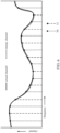
- FIG. 6 illustrates example interpolation-based CSI feedback or demodulation frequency locations varying in time, in accordance with certain aspects of the present disclosure. As shown in FIG. 6 , some lines correspond to feedback at time instance T 0 and the other lines correspond to feedback at time T 1 . As shown, the frequency locations vary over time instances T 0 and T 1 . This may allow interpolation across both frequency and time. Interpolation in time corresponds to interpolating across CSI information reported in different subframes. For example, more outdated reports should carry less weight in the interpolation procedure compared to more recent reports.
- CSI may be computed based on channel and interference measurements. Averaging may be performed on a wideband/subband level. According to certain aspects, interpolation may not apply to interference measurements where there is no frequency correlation for interference. For MPE, interference may capture only interference from cells with which no coordination is performed. Interference estimation may be common across the transmission points for which feedback is provided-which may reflect uncoordinated interference. CQI for each transmission point may be provided and may be used for inter-point amplitude feedback. For example, the CQI level-which may represent channel strength relative to the common interference level-may reflect the amplitude relation between the transmission points. Interference estimation may continue to be performed on a wideband/subband level.
- interpolation-based demodulation may be performed.
- PRB bundling typically requires the network to select one precoder per PRG when PMI/CQI feedback is configured. This may impair nulling gains because the precoder may not be adapted per PRB or per tone.
- performing interpolation-based CSI estimation at the receiver may avoid impact to nulling gains at the expense of some channel estimation loss due to the lack of PRB bundling.
- DM-RS may be used for demodulation.
- DM-RS is a precoded reference signal.
- DM-RS may enable non-codebook based precoding.
- the UE may estimate the channel per DM-RS frequency location, without assuming bundling.
- the precoder may be assumed fixed across a single PRB. Alternatively, the precoder may change per subcarrier. In this case, the UE may perform estimation separately per DM-RS frequency location.
- filtering across multiple frequency locations may be used to suppress estimation errors; however, the final CSI estimates should be representative of each frequency location and not representative of an average across several frequency locations.
- the UE may interpolate the channel estimates-which include precoding-and perform demodulation based on the interpolated values. The UE may assume that the transmission rank remains fixed across the system bandwidth.
- various interpolation techniques may be performed.
- the UE may perform vector-based interpolation of channel directions.
- the UE may avoid interpolation per vector element, instead, the UE may interpolate the direction of the channel directly (e.g., through geodesic interpolation).
- Vector-based interpolation of channel directions may be well suited for CSI feedback where channel directions consist of unit-norm vectors.
- the UE may perform per-element interpolation for vectors or matrices by interpolating each element of the vector/matrix independently.
- Per-element interpolation may be well suited for interpolation-based CSI estimation for demodulation.
- the UE may interpolate the channel matrix-including precoding-for each combination of DM-RS antenna port and UE receive antenna, separately.
- FIG. 7 illustrates example operations 700 for wireless communications, in accordance with certain aspects of the present disclosure.
- the operations 700 may be performed, for example, by a UE (e.g., UE 120).
- the operations 700 may begin, at 702, by performing channel estimation at a plurality of frequency locations based on RSs transmitted from at least one transmission point.
- the frequency locations may correspond to REs used to transmit the RSs.
- the UE may receive signaling indicating a granularity of the frequency locations. Additionally, the UE may perform filtering to remove errors in the channel estimation.
- the UE may compute at least one channel feedback metric for each frequency location. For example, the UE may compute channel matrix elements calculated as part of the channel estimation. As another example, the UE may compute a PMI or a CQI for each frequency location. As yet another example, the UE may compute a channel direction for each frequency location. According to certain aspects, the UE may compute inter-point amplitude and phase information.
- the UE may transmit the channel feedback metrics to the at least one transmission point.
- the signaling indicates different granularities for different transmission points.
- the feedback may be provided periodically. For example, feedback for different frequency locations may be reported in different subframes. Alternatively, the feedback may be provided aperiodically. For example, feedback for all frequency locations may be provided in a single report.
- FIG. 8 illustrates example operations 800 for wireless communications, in accordance with certain aspects of the present disclosure.
- the operations 800 may be performed, for example, by a BS (e.g., BS 110).
- the operations 800 may begin, at 802, by receiving channel feedback metrics from a UE, calculated at a plurality of frequency locations based on RSs transmitted from the BS.
- the BS may receive a PMI or a CQI for each frequency location.
- the BS may receive a channel direction for each frequency location or channel matrix elements calculated by the UE as part of the channel estimation.
- the channel feedback metrics for each frequency location may be based, at least in part, on RSs transmitted from another BS.
- the channel feedback metrics may be received periodically. For example, channel feedback metrics for different frequency locations may be reported in different subframes. For certain embodiments, the channel feedback metrics may be provided aperiodically. For example, feedback for all frequency locations may be provided in a single report. According to certain aspects, the frequency locations may correspond to REs used to transmit the RSs
- the BS may perform interpolation to determine values for channel feedback metrics for frequency locations between frequency locations of the received channel feedback metrics. For example, the BS may perform vector-based interpolation of channel directions. Alternatively, the BS may perform per-element interpolation for vectors or matrices by interpolating each element of the vector or matrix independently.
- the BS may transmit signaling to the UE indicating a granularity of the frequency locations.
- the signaling may indicate different granularities for different transmission points.
- the signaling may be based on the frequency selectivity across a range of the frequency locations or long-term channel strength of a cell of the BS.
- FIG. 9 illustrates example operations 900 for wireless communications, in accordance with certain aspects of the present disclosure.
- the operations 900 may be performed, for example, by a UE (e.g., UE 120).
- the operations 900 may begin, at 902, by performing channel estimation at a plurality of frequency location based on RSs transmitted from at least one transmission point.
- the frequency locations may correspond to REs used to transmit the DM-RS.
- the UE may estimate the channel per DM-RS frequency location without assuming bundling in which precoding is fixed across a PRG.
- the UE may perform interpolation to determine values for channel estimates for frequency locations between the plurality of frequency locations. And at 906, the UE may perform demodulation based, at least in part, on the interpolated values.
- DSP digital signal processor
- ASIC application specific integrated circuit
- FPGA field programmable gate array
- a general-purpose processor may be a microprocessor, but in the alternative, the processor may be any conventional processor, controller, microcontroller or state machine.
- a processor may also be implemented as a combination of computing devices, e.g., a combination of a DSP and a microprocessor, a plurality of microprocessors, one or more microprocessors in conjunction with a DSP core, or any other such configuration.
- a software module may reside in RAM memory, flash memory, ROM memory, EPROM memory, EEPROM memory, registers, hard disk, a removable disk, a CD-ROM or any other form of storage medium known in the art.
- An exemplary storage medium is coupled to the processor such that the processor can read information from, and/or write information to, the storage medium.
- the storage medium may be integral to the processor.
- the processor and the storage medium may reside in an ASIC.
- the ASIC may reside in a user terminal.
- the processor and the storage medium may reside as discrete components in a user terminal.
- the functions described may be implemented in hardware, software, firmware or any combination thereof. If implemented in software, the functions may be stored on or transmitted over as one or more instructions or code on a computer-readable medium.
- Computer-readable media includes both computer storage media and communication media including any medium that facilitates transfer of a computer program from one place to another.
- a storage media may be any available media that can be accessed by a general purpose or special purpose computer.
- such computer-readable media can comprise RAM, ROM, EEPROM, CD-ROM or other optical disk storage, magnetic disk storage or other magnetic storage devices, or any other medium that can be used to carry or store desired program code means in the form of instructions or data structures and that can be accessed by a general-purpose or special-purpose computer, or a general-purpose or special-purpose processor. Also, any connection is properly termed a computer-readable medium.
- Disk and disc includes compact disc (CD), laser disc, optical disc, digital versatile disc (DVD), floppy disk and blu-ray disc where disks usually reproduce data magnetically, while discs reproduce data optically with lasers. Combinations of the above should also be included within the scope of computer-readable media.
Landscapes
- Engineering & Computer Science (AREA)
- Computer Networks & Wireless Communication (AREA)
- Signal Processing (AREA)
- Quality & Reliability (AREA)
- Mobile Radio Communication Systems (AREA)
- Physics & Mathematics (AREA)
- Mathematical Physics (AREA)
- Radio Transmission System (AREA)
Claims (10)
- Verfahren (700) zur drahtlosen Kommunikation durch ein Benutzergerät, UE, umfassend:Empfangen einer Signalisierung, die eine Granularität von Frequenzpositionen zum Anpassen einer Rückkopplungsgranularität an eine Frequenzselektivität von mindestens einem Übertragungspunkt angibt;Durchführen (702) einer Kanalschätzung an einer Mehrzahl von Frequenzpositionen basierend auf Referenzsignalen, RSS, die von dem mindestens einen Übertragungspunkt übertragen werden, wobei die Frequenzpositionen der angegebenen Granularität und Ressourcenelementen, REs, entsprechen, die zum Übertragen der Referenzsignale verwendet werden;Berechnen (704) mindestens einer Kanalrückkopplungsmetrik für jede Frequenzposition, undÜbertragen (706) der Kanalrückkopplungsmetriken an den mindestens einen Übertragungspunkt;wobei:das Durchführen der Kanalschätzung das Durchführen einer Kanalschätzung an der Mehrzahl von Frequenzpositionen basierend auf RSs umfasst, die von mindestens ersten und zweiten Übertragungspunkten übertragen werden; undBerechnen der Kanalrückkopplungsmetrik für jede Frequenzposition das Berechnen von Inter-Punktamplituden- und Phaseninformationen für jeden der ersten und zweiten Übertragungspunkte umfasst.
- Verfahren (700) nach Anspruch 1, ferner umfassend Filtern, um Fehler in der Kanalschätzung zu entfernen.
- Verfahren (700) nach Anspruch 1, wobei Berechnen mindestens einer Kanalrückkopplungsmetrik für jede Frequenzposition Berechnen mindestens eines von einem Vorcodierermatrixindikator, PMI, oder einem Kanalqualitätsindikator, CQI, für jede Frequenzposition umfasst.
- Verfahren (700) nach Anspruch 1, wobei Berechnen mindestens einer Kanalrückkopplungsmetrik für jede Frequenzposition Berechnen einer Kanalrichtung für jede Frequenzposition umfasst.
- Verfahren (700) nach Anspruch 1, wobei die Kanalrückkopplungsmetriken Kanalmatrixelemente umfassen, die als Teil der Kanalschätzung berechnet werden.
- Verfahren (700) nach Anspruch 1, wobei die Kanalrückkopplungsmetriken periodisch bereitgestellt werden.
- Verfahren nach Anspruch 6, wobei Rückkopplung für verschiedene Frequenzpositionen in verschiedenen Unterrahmen berichtet wird.
- Verfahren (700) nach Anspruch 1, wobei die Kanalrückkopplungsmetriken periodisch bereitgestellt werden und die Kanalrückkopplungsmetriken für alle Frequenzpositionen in einem einzigen Bericht bereitgestellt werden.
- Vorrichtung zur drahtlosen Kommunikation durch ein Benutzergerät, UE, wobei die Vorrichtung angepasst ist, um eine Signalisierung zu empfangen, die eine Granularität von Frequenzpositionen zum Anpassen einer Rückkopplungsgranularität an eine Frequenzselektivität von mindestens einem Übertragungspunkt angibt, und umfasst:Mittel zum Durchführen (702) einer Kanalschätzung an einer Mehrzahl von Frequenzpositionen basierend auf Referenzsignalen, RSs, die von dem mindestens einen Übertragungspunkt übertragen werden, wobei die Frequenzpositionen der angegebenen Granularität und Ressourcenelementen, REs, entsprechen, die zum Übertragen der Referenzsignale verwendet werden;Mittel zum Berechnen (704) mindestens einer Kanalrückkopplungsmetrik für jede Frequenzposition; undMittel zum Übertragen (706) der Kanalrückkopplungsmetriken an den mindestens einen Übertragungspunkt,wobei:das Mittel zum Durchführen (702) einer Kanalschätzung angepasst sind, um eine Kanalschätzung an der Mehrzahl von Frequenzpositionen basierend auf RSs durchzuführen, die von mindestens ersten und zweiten Übertragungspunkten übertragen werden; undwobei das Mittel zum Berechnen (704) der Kanalrückkopplungsmetrik angepasst sind, um Inter-Punktamplituden- und Phaseninformationen für jeden der ersten undzweiten Übertragungspunkte zu berechnen.
- Computerprogramm, umfassend Programmanweisungen, die, wenn sie auf einem Computer ausgeführt werden, den Computer veranlassen, alle Schritte des Verfahrens nach einem der Ansprüche 1 bis 8 durchzuführen.
Applications Claiming Priority (3)
| Application Number | Priority Date | Filing Date | Title |
|---|---|---|---|
| US201361754135P | 2013-01-18 | 2013-01-18 | |
| US14/155,661 US9503924B2 (en) | 2013-01-18 | 2014-01-15 | Interpolation-based channel state information (CSI) enhancements in long-term evolution (LTE) |
| PCT/US2014/011770 WO2014113523A1 (en) | 2013-01-18 | 2014-01-16 | Interpolation-based channel state information (csi) ehancements in long-term evolution (lte) |
Publications (2)
| Publication Number | Publication Date |
|---|---|
| EP2946510A1 EP2946510A1 (de) | 2015-11-25 |
| EP2946510B1 true EP2946510B1 (de) | 2023-05-10 |
Family
ID=51207592
Family Applications (1)
| Application Number | Title | Priority Date | Filing Date |
|---|---|---|---|
| EP14703985.3A Active EP2946510B1 (de) | 2013-01-18 | 2014-01-16 | Interpolationsbasierte kanalzustandsinformationserweiterungen in einer langfristigen evolution (lte) |
Country Status (6)
| Country | Link |
|---|---|
| US (1) | US9503924B2 (de) |
| EP (1) | EP2946510B1 (de) |
| JP (2) | JP6580492B2 (de) |
| KR (1) | KR20150107776A (de) |
| CN (1) | CN104919737B (de) |
| WO (1) | WO2014113523A1 (de) |
Families Citing this family (19)
| Publication number | Priority date | Publication date | Assignee | Title |
|---|---|---|---|---|
| WO2015009929A1 (en) | 2013-07-18 | 2015-01-22 | Propeller, Inc. | Ice mold |
| CN105450560B (zh) | 2014-08-14 | 2019-02-12 | 华为技术有限公司 | 一种信道反馈传输的方法 |
| US9985700B2 (en) * | 2015-05-12 | 2018-05-29 | Mediatek Inc. | Channel state feedback enhancement in downlink multiuser superposition transmission |
| WO2017156703A1 (zh) * | 2016-03-15 | 2017-09-21 | 华为技术有限公司 | 一种处理解调参考信号的方法及设备 |
| US10116483B2 (en) * | 2016-04-18 | 2018-10-30 | Qualcomm Incorporated | Dynamically convey information of demodulation reference signal and phase noise compensation reference signal |
| CN108713299B (zh) * | 2016-04-29 | 2020-07-24 | 华为技术有限公司 | 上行资源分配与信号调制方法及装置 |
| AU2017394106A1 (en) * | 2017-01-17 | 2019-08-29 | Guangdong Oppo Mobile Telecommunications Corp., Ltd. | Signal transmission method and apparatus |
| US10396914B2 (en) * | 2017-01-19 | 2019-08-27 | Qualcomm Incorporated | Reference signal measurement filtering in multi-beam operation |
| US11785565B2 (en) | 2017-04-14 | 2023-10-10 | Qualcomm Incorporated | Band-dependent configuration for synchronization |
| WO2018201456A1 (en) * | 2017-05-05 | 2018-11-08 | Qualcomm Incorporated | Partial band configuration for channel state information |
| CN110663279B (zh) * | 2017-05-16 | 2023-05-30 | 中兴通讯股份有限公司 | 广播反馈机制 |
| US10834689B2 (en) * | 2017-08-15 | 2020-11-10 | At&T Intellectual Property I, L.P. | Base station wireless channel sounding |
| SG11202005309UA (en) * | 2017-12-28 | 2020-07-29 | Beijing Xiaomi Mobile Software Co Ltd | Path loss determination method and apparatus |
| US10812216B2 (en) | 2018-11-05 | 2020-10-20 | XCOM Labs, Inc. | Cooperative multiple-input multiple-output downlink scheduling |
| US10756860B2 (en) | 2018-11-05 | 2020-08-25 | XCOM Labs, Inc. | Distributed multiple-input multiple-output downlink configuration |
| KR20240046312A (ko) * | 2018-11-05 | 2024-04-08 | 엑스콤 랩스 인코퍼레이티드 | 협력 다중 입력 다중 출력 다운링크 스케줄링 |
| US10659112B1 (en) | 2018-11-05 | 2020-05-19 | XCOM Labs, Inc. | User equipment assisted multiple-input multiple-output downlink configuration |
| US11750258B2 (en) * | 2020-03-12 | 2023-09-05 | Samsung Electronics Co., Ltd. | Method and apparatus for CSI reporting |
| US11973618B2 (en) * | 2020-08-13 | 2024-04-30 | Intel Corporation | Algorithm and architecture for channel estimation in 5G new radio |
Family Cites Families (25)
| Publication number | Priority date | Publication date | Assignee | Title |
|---|---|---|---|---|
| JP4657888B2 (ja) * | 2005-10-31 | 2011-03-23 | シャープ株式会社 | 送信機及び送信方法 |
| US8213943B2 (en) * | 2007-05-02 | 2012-07-03 | Qualcomm Incorporated | Constrained hopping of DL reference signals |
| GB0720723D0 (en) * | 2007-10-23 | 2007-12-05 | Icera Inc | Reporting channel quality information |
| US8699529B2 (en) * | 2008-03-28 | 2014-04-15 | Qualcomm Incorporated | Broadband pilot channel estimation using a reduced order FFT and a hardware interpolator |
| CN103560871B (zh) * | 2008-04-25 | 2017-03-22 | 夏普株式会社 | 基站装置、移动台装置以及通信方法 |
| US9077531B2 (en) * | 2008-09-25 | 2015-07-07 | Lg Electronics Inc. | Hybrid automatic repeat request and channel information feedback for relay |
| US9019902B2 (en) * | 2008-11-11 | 2015-04-28 | Qualcomm Incorporated | Channel quality feedback in multicarrier systems |
| CN102439869B (zh) | 2009-01-30 | 2014-12-03 | 诺基亚公司 | 多用户mimo干扰抑制通信系统和方法 |
| JP5059800B2 (ja) * | 2009-03-16 | 2012-10-31 | 株式会社エヌ・ティ・ティ・ドコモ | 無線基地局装置及び移動局装置、無線通信方法 |
| CN101867464B (zh) * | 2009-04-17 | 2012-12-12 | 华为技术有限公司 | 一种信道信息反馈方法、终端、基站及多输入多输出系统 |
| EP2433376A4 (de) * | 2009-04-28 | 2014-12-03 | Nokia Corp | Feedback für kanalstatusinformationen |
| US20100284447A1 (en) * | 2009-05-11 | 2010-11-11 | Qualcomm Incorporated | Frequency domain feedback channel estimation for an interference cancellation repeater including sampling of non causal taps |
| JP2011004161A (ja) * | 2009-06-18 | 2011-01-06 | Sharp Corp | 通信システム、通信装置および通信方法 |
| CN102577164B (zh) * | 2009-07-17 | 2015-03-04 | Lg电子株式会社 | 在包括中继站的无线通信系统中发射基准信号的方法和设备 |
| US9432977B2 (en) * | 2009-09-30 | 2016-08-30 | Lg Electronics Inc. | Apparatus and method for transmitting uplink control information |
| CN102726016B (zh) | 2009-12-04 | 2015-11-25 | 爱立信(中国)通信有限公司 | 用于无线通信系统中信道估计的设备和方法 |
| JP5276047B2 (ja) * | 2010-04-30 | 2013-08-28 | 株式会社エヌ・ティ・ティ・ドコモ | 移動端末装置 |
| JP2012004609A (ja) * | 2010-06-14 | 2012-01-05 | Sharp Corp | 基地局装置、端末装置、通信システムおよび通信方法 |
| CN102377527B (zh) * | 2010-08-09 | 2014-12-24 | 上海贝尔股份有限公司 | 一种降低多小区反馈开销的方法和装置 |
| US20130039291A1 (en) | 2011-08-12 | 2013-02-14 | Research In Motion Limited | Design on Enhanced Control Channel for Wireless System |
| US8743785B2 (en) * | 2011-08-15 | 2014-06-03 | Futurewei Technologies, Inc. | System and method for reducing interference |
| US9258039B2 (en) | 2011-09-08 | 2016-02-09 | Qualcomm Incorporated | Devices for sending and receiving quantization quality feedback |
| KR101855523B1 (ko) * | 2011-10-06 | 2018-05-04 | 삼성전자주식회사 | 통신 시스템에서 피드백 생성 방법 및 장치 |
| US9198070B2 (en) * | 2012-05-14 | 2015-11-24 | Google Technology Holdings LLC | Radio link monitoring in a wireless communication device |
| EP3252986B1 (de) * | 2012-08-10 | 2021-10-06 | Huawei Technologies Co., Ltd. | Verfahren und knoten in einem drahtloskommunikationssystem |
-
2014
- 2014-01-15 US US14/155,661 patent/US9503924B2/en active Active
- 2014-01-16 JP JP2015553814A patent/JP6580492B2/ja active Active
- 2014-01-16 KR KR1020157021029A patent/KR20150107776A/ko not_active Application Discontinuation
- 2014-01-16 WO PCT/US2014/011770 patent/WO2014113523A1/en active Application Filing
- 2014-01-16 CN CN201480004514.2A patent/CN104919737B/zh active Active
- 2014-01-16 EP EP14703985.3A patent/EP2946510B1/de active Active
-
2018
- 2018-01-26 JP JP2018011628A patent/JP6462912B2/ja active Active
Non-Patent Citations (2)
| Title |
|---|
| FUJITSU: "Consideration on CSI Feedback to support DL CoMP", 3GPP DRAFT; R1-114180_CONSIDERATION ON CSI FEEDBACK TO SUPPORT DL COMP, 3RD GENERATION PARTNERSHIP PROJECT (3GPP), MOBILE COMPETENCE CENTRE ; 650, ROUTE DES LUCIOLES ; F-06921 SOPHIA-ANTIPOLIS CEDEX ; FRANCE, vol. RAN WG1, no. San Francisco, USA; 20111114 - 20111118, 9 November 2011 (2011-11-09), XP050562306 * |
| FUJITSU: "On the need of inter-CSI-RS-resource phase/amplitude feedback", 3GPP DRAFT; R1-120746_ ON THE NEED OF INTER-CSI-RS-RESOURCE PHASE OR AMPLITUDE FEEDBACK_ FUJITSU, 3RD GENERATION PARTNERSHIP PROJECT (3GPP), MOBILE COMPETENCE CENTRE ; 650, ROUTE DES LUCIOLES ; F-06921 SOPHIA-ANTIPOLIS CEDEX ; FRANCE, vol. RAN WG1, no. Dresden, Gemany; 20120206 - 20120210, 1 February 2012 (2012-02-01), XP050563271 * |
Also Published As
| Publication number | Publication date |
|---|---|
| WO2014113523A1 (en) | 2014-07-24 |
| KR20150107776A (ko) | 2015-09-23 |
| JP6462912B2 (ja) | 2019-01-30 |
| JP6580492B2 (ja) | 2019-09-25 |
| US9503924B2 (en) | 2016-11-22 |
| JP2016509798A (ja) | 2016-03-31 |
| US20140204782A1 (en) | 2014-07-24 |
| JP2018117352A (ja) | 2018-07-26 |
| CN104919737B (zh) | 2019-06-11 |
| EP2946510A1 (de) | 2015-11-25 |
| CN104919737A (zh) | 2015-09-16 |
Similar Documents
| Publication | Publication Date | Title |
|---|---|---|
| EP2946510B1 (de) | Interpolationsbasierte kanalzustandsinformationserweiterungen in einer langfristigen evolution (lte) | |
| CN114826351B (zh) | 针对新无线电技术多输入多输出通信的动态多波束传输 | |
| CN106134124B (zh) | 用于信道状态反馈和传输点选择的csi-rs的联合传输 | |
| US9509426B2 (en) | Interference estimation resource definition and usage for enhanced receivers | |
| US10687225B2 (en) | System and method for providing interference characteristics for interference mitigation | |
| US9107104B2 (en) | Method and apparatus for channel feedback based on reference signal | |
| EP2748943B1 (de) | Benutzergeräterweiterungen für kooperative mehrpunktkommunikation | |
| US20110249584A1 (en) | Periodic cqi reporting in a wireless communication network | |
| US20200120005A1 (en) | Cell-specific reference signal interference averaging | |
| US20150098411A1 (en) | System And Method For Providing Interference Characteristics For Interference Mitigation |
Legal Events
| Date | Code | Title | Description |
|---|---|---|---|
| PUAI | Public reference made under article 153(3) epc to a published international application that has entered the european phase |
Free format text: ORIGINAL CODE: 0009012 |
|
| 17P | Request for examination filed |
Effective date: 20150721 |
|
| AK | Designated contracting states |
Kind code of ref document: A1 Designated state(s): AL AT BE BG CH CY CZ DE DK EE ES FI FR GB GR HR HU IE IS IT LI LT LU LV MC MK MT NL NO PL PT RO RS SE SI SK SM TR |
|
| AX | Request for extension of the european patent |
Extension state: BA ME |
|
| DAX | Request for extension of the european patent (deleted) | ||
| STAA | Information on the status of an ep patent application or granted ep patent |
Free format text: STATUS: EXAMINATION IS IN PROGRESS |
|
| 17Q | First examination report despatched |
Effective date: 20180222 |
|
| STAA | Information on the status of an ep patent application or granted ep patent |
Free format text: STATUS: EXAMINATION IS IN PROGRESS |
|
| STAA | Information on the status of an ep patent application or granted ep patent |
Free format text: STATUS: EXAMINATION IS IN PROGRESS |
|
| GRAP | Despatch of communication of intention to grant a patent |
Free format text: ORIGINAL CODE: EPIDOSNIGR1 |
|
| STAA | Information on the status of an ep patent application or granted ep patent |
Free format text: STATUS: GRANT OF PATENT IS INTENDED |
|
| INTG | Intention to grant announced |
Effective date: 20230109 |
|
| GRAS | Grant fee paid |
Free format text: ORIGINAL CODE: EPIDOSNIGR3 |
|
| GRAA | (expected) grant |
Free format text: ORIGINAL CODE: 0009210 |
|
| STAA | Information on the status of an ep patent application or granted ep patent |
Free format text: STATUS: THE PATENT HAS BEEN GRANTED |
|
| AK | Designated contracting states |
Kind code of ref document: B1 Designated state(s): AL AT BE BG CH CY CZ DE DK EE ES FI FR GB GR HR HU IE IS IT LI LT LU LV MC MK MT NL NO PL PT RO RS SE SI SK SM TR |
|
| REG | Reference to a national code |
Ref country code: GB Ref legal event code: FG4D |
|
| REG | Reference to a national code |
Ref country code: AT Ref legal event code: REF Ref document number: 1567772 Country of ref document: AT Kind code of ref document: T Effective date: 20230515 Ref country code: CH Ref legal event code: EP |
|
| REG | Reference to a national code |
Ref country code: DE Ref legal event code: R096 Ref document number: 602014086887 Country of ref document: DE |
|
| REG | Reference to a national code |
Ref country code: IE Ref legal event code: FG4D |
|
| REG | Reference to a national code |
Ref country code: LT Ref legal event code: MG9D |
|
| REG | Reference to a national code |
Ref country code: NL Ref legal event code: MP Effective date: 20230510 |
|
| REG | Reference to a national code |
Ref country code: AT Ref legal event code: MK05 Ref document number: 1567772 Country of ref document: AT Kind code of ref document: T Effective date: 20230510 |
|
| PG25 | Lapsed in a contracting state [announced via postgrant information from national office to epo] |
Ref country code: SE Free format text: LAPSE BECAUSE OF FAILURE TO SUBMIT A TRANSLATION OF THE DESCRIPTION OR TO PAY THE FEE WITHIN THE PRESCRIBED TIME-LIMIT Effective date: 20230510 Ref country code: PT Free format text: LAPSE BECAUSE OF FAILURE TO SUBMIT A TRANSLATION OF THE DESCRIPTION OR TO PAY THE FEE WITHIN THE PRESCRIBED TIME-LIMIT Effective date: 20230911 Ref country code: NO Free format text: LAPSE BECAUSE OF FAILURE TO SUBMIT A TRANSLATION OF THE DESCRIPTION OR TO PAY THE FEE WITHIN THE PRESCRIBED TIME-LIMIT Effective date: 20230810 Ref country code: NL Free format text: LAPSE BECAUSE OF FAILURE TO SUBMIT A TRANSLATION OF THE DESCRIPTION OR TO PAY THE FEE WITHIN THE PRESCRIBED TIME-LIMIT Effective date: 20230510 Ref country code: ES Free format text: LAPSE BECAUSE OF FAILURE TO SUBMIT A TRANSLATION OF THE DESCRIPTION OR TO PAY THE FEE WITHIN THE PRESCRIBED TIME-LIMIT Effective date: 20230510 Ref country code: AT Free format text: LAPSE BECAUSE OF FAILURE TO SUBMIT A TRANSLATION OF THE DESCRIPTION OR TO PAY THE FEE WITHIN THE PRESCRIBED TIME-LIMIT Effective date: 20230510 |
|
| PG25 | Lapsed in a contracting state [announced via postgrant information from national office to epo] |
Ref country code: RS Free format text: LAPSE BECAUSE OF FAILURE TO SUBMIT A TRANSLATION OF THE DESCRIPTION OR TO PAY THE FEE WITHIN THE PRESCRIBED TIME-LIMIT Effective date: 20230510 Ref country code: PL Free format text: LAPSE BECAUSE OF FAILURE TO SUBMIT A TRANSLATION OF THE DESCRIPTION OR TO PAY THE FEE WITHIN THE PRESCRIBED TIME-LIMIT Effective date: 20230510 Ref country code: LV Free format text: LAPSE BECAUSE OF FAILURE TO SUBMIT A TRANSLATION OF THE DESCRIPTION OR TO PAY THE FEE WITHIN THE PRESCRIBED TIME-LIMIT Effective date: 20230510 Ref country code: LT Free format text: LAPSE BECAUSE OF FAILURE TO SUBMIT A TRANSLATION OF THE DESCRIPTION OR TO PAY THE FEE WITHIN THE PRESCRIBED TIME-LIMIT Effective date: 20230510 Ref country code: IS Free format text: LAPSE BECAUSE OF FAILURE TO SUBMIT A TRANSLATION OF THE DESCRIPTION OR TO PAY THE FEE WITHIN THE PRESCRIBED TIME-LIMIT Effective date: 20230910 Ref country code: HR Free format text: LAPSE BECAUSE OF FAILURE TO SUBMIT A TRANSLATION OF THE DESCRIPTION OR TO PAY THE FEE WITHIN THE PRESCRIBED TIME-LIMIT Effective date: 20230510 Ref country code: GR Free format text: LAPSE BECAUSE OF FAILURE TO SUBMIT A TRANSLATION OF THE DESCRIPTION OR TO PAY THE FEE WITHIN THE PRESCRIBED TIME-LIMIT Effective date: 20230811 |
|
| PG25 | Lapsed in a contracting state [announced via postgrant information from national office to epo] |
Ref country code: FI Free format text: LAPSE BECAUSE OF FAILURE TO SUBMIT A TRANSLATION OF THE DESCRIPTION OR TO PAY THE FEE WITHIN THE PRESCRIBED TIME-LIMIT Effective date: 20230510 |
|
| PG25 | Lapsed in a contracting state [announced via postgrant information from national office to epo] |
Ref country code: SK Free format text: LAPSE BECAUSE OF FAILURE TO SUBMIT A TRANSLATION OF THE DESCRIPTION OR TO PAY THE FEE WITHIN THE PRESCRIBED TIME-LIMIT Effective date: 20230510 |
|
| PGFP | Annual fee paid to national office [announced via postgrant information from national office to epo] |
Ref country code: GB Payment date: 20231218 Year of fee payment: 11 |
|
| PG25 | Lapsed in a contracting state [announced via postgrant information from national office to epo] |
Ref country code: SM Free format text: LAPSE BECAUSE OF FAILURE TO SUBMIT A TRANSLATION OF THE DESCRIPTION OR TO PAY THE FEE WITHIN THE PRESCRIBED TIME-LIMIT Effective date: 20230510 Ref country code: SK Free format text: LAPSE BECAUSE OF FAILURE TO SUBMIT A TRANSLATION OF THE DESCRIPTION OR TO PAY THE FEE WITHIN THE PRESCRIBED TIME-LIMIT Effective date: 20230510 Ref country code: RO Free format text: LAPSE BECAUSE OF FAILURE TO SUBMIT A TRANSLATION OF THE DESCRIPTION OR TO PAY THE FEE WITHIN THE PRESCRIBED TIME-LIMIT Effective date: 20230510 Ref country code: EE Free format text: LAPSE BECAUSE OF FAILURE TO SUBMIT A TRANSLATION OF THE DESCRIPTION OR TO PAY THE FEE WITHIN THE PRESCRIBED TIME-LIMIT Effective date: 20230510 Ref country code: DK Free format text: LAPSE BECAUSE OF FAILURE TO SUBMIT A TRANSLATION OF THE DESCRIPTION OR TO PAY THE FEE WITHIN THE PRESCRIBED TIME-LIMIT Effective date: 20230510 Ref country code: CZ Free format text: LAPSE BECAUSE OF FAILURE TO SUBMIT A TRANSLATION OF THE DESCRIPTION OR TO PAY THE FEE WITHIN THE PRESCRIBED TIME-LIMIT Effective date: 20230510 |
|
| PGFP | Annual fee paid to national office [announced via postgrant information from national office to epo] |
Ref country code: FR Payment date: 20231214 Year of fee payment: 11 |
|
| REG | Reference to a national code |
Ref country code: DE Ref legal event code: R097 Ref document number: 602014086887 Country of ref document: DE |
|
| PLBE | No opposition filed within time limit |
Free format text: ORIGINAL CODE: 0009261 |
|
| STAA | Information on the status of an ep patent application or granted ep patent |
Free format text: STATUS: NO OPPOSITION FILED WITHIN TIME LIMIT |
|
| 26N | No opposition filed |
Effective date: 20240213 |
|
| PGFP | Annual fee paid to national office [announced via postgrant information from national office to epo] |
Ref country code: DE Payment date: 20231128 Year of fee payment: 11 |
|
| PG25 | Lapsed in a contracting state [announced via postgrant information from national office to epo] |
Ref country code: SI Free format text: LAPSE BECAUSE OF FAILURE TO SUBMIT A TRANSLATION OF THE DESCRIPTION OR TO PAY THE FEE WITHIN THE PRESCRIBED TIME-LIMIT Effective date: 20230510 |
|
| PG25 | Lapsed in a contracting state [announced via postgrant information from national office to epo] |
Ref country code: SI Free format text: LAPSE BECAUSE OF FAILURE TO SUBMIT A TRANSLATION OF THE DESCRIPTION OR TO PAY THE FEE WITHIN THE PRESCRIBED TIME-LIMIT Effective date: 20230510 Ref country code: IT Free format text: LAPSE BECAUSE OF FAILURE TO SUBMIT A TRANSLATION OF THE DESCRIPTION OR TO PAY THE FEE WITHIN THE PRESCRIBED TIME-LIMIT Effective date: 20230510 |