EP2945842B1 - Trainingsgerät - Google Patents
Trainingsgerät Download PDFInfo
- Publication number
- EP2945842B1 EP2945842B1 EP14706266.5A EP14706266A EP2945842B1 EP 2945842 B1 EP2945842 B1 EP 2945842B1 EP 14706266 A EP14706266 A EP 14706266A EP 2945842 B1 EP2945842 B1 EP 2945842B1
- Authority
- EP
- European Patent Office
- Prior art keywords
- bearing
- training device
- crank
- outer shaft
- bearings
- Prior art date
- Legal status (The legal status is an assumption and is not a legal conclusion. Google has not performed a legal analysis and makes no representation as to the accuracy of the status listed.)
- Not-in-force
Links
Images

Classifications
-
- B—PERFORMING OPERATIONS; TRANSPORTING
- B62—LAND VEHICLES FOR TRAVELLING OTHERWISE THAN ON RAILS
- B62M—RIDER PROPULSION OF WHEELED VEHICLES OR SLEDGES; POWERED PROPULSION OF SLEDGES OR SINGLE-TRACK CYCLES; TRANSMISSIONS SPECIALLY ADAPTED FOR SUCH VEHICLES
- B62M3/00—Construction of cranks operated by hand or foot
-
- B—PERFORMING OPERATIONS; TRANSPORTING
- B62—LAND VEHICLES FOR TRAVELLING OTHERWISE THAN ON RAILS
- B62K—CYCLES; CYCLE FRAMES; CYCLE STEERING DEVICES; RIDER-OPERATED TERMINAL CONTROLS SPECIALLY ADAPTED FOR CYCLES; CYCLE AXLE SUSPENSIONS; CYCLE SIDECARS, FORECARS, OR THE LIKE
- B62K19/00—Cycle frames
- B62K19/30—Frame parts shaped to receive other cycle parts or accessories
- B62K19/34—Bottom brackets
-
- B—PERFORMING OPERATIONS; TRANSPORTING
- B62—LAND VEHICLES FOR TRAVELLING OTHERWISE THAN ON RAILS
- B62M—RIDER PROPULSION OF WHEELED VEHICLES OR SLEDGES; POWERED PROPULSION OF SLEDGES OR SINGLE-TRACK CYCLES; TRANSMISSIONS SPECIALLY ADAPTED FOR SUCH VEHICLES
- B62M3/00—Construction of cranks operated by hand or foot
- B62M3/003—Combination of crank axles and bearings housed in the bottom bracket
-
- B—PERFORMING OPERATIONS; TRANSPORTING
- B62—LAND VEHICLES FOR TRAVELLING OTHERWISE THAN ON RAILS
- B62M—RIDER PROPULSION OF WHEELED VEHICLES OR SLEDGES; POWERED PROPULSION OF SLEDGES OR SINGLE-TRACK CYCLES; TRANSMISSIONS SPECIALLY ADAPTED FOR SUCH VEHICLES
- B62M3/00—Construction of cranks operated by hand or foot
- B62M2003/006—Crank arrangements to overcome dead points
Definitions
- the invention relates to a training device according to the preamble of claim 1.
- crank bearings are known whose cranks are mounted independently rotatably.
- the cranks are each mounted on a separate attached to the frame of a training device or vehicle bearing journals.
- the bearings are very wide to accommodate the forces in a floating bearing / bearing combination. This results in a very large construction, which significantly increases the distance between the pedals attached to the cranks, with the disadvantage that the installed crankshaft bearings are usually very solid and, above all, wide.
- the attached to the crank arms pedals therefore have a large distance from each other and change the lever arm and the pressure kinematics in the extremities of the users.
- people with joint problems and exercise equipment with decoupled cranks will not be able to use these devices or healthy individuals will be exposed to increased levels of stress that may have negative effects on the musculoskeletal system.
- the object of the invention is therefore to provide a narrow, small-sized crank bearing with two decoupled cranks.
- crank bearing a double bearing block with a recess, an outer shaft having a central recess, wherein the outer shaft is mounted in the recess of the double bearing block by means of a first bearing, and an inner shaft, by means of a second bearing in the recess of the outer shaft is mounted, wherein the inner shaft, the outer shaft and the recess of the Doppellagerbocks are coaxially arranged and have a common axis of rotation.
- the storage of the inner shaft in the outer shaft with the double bearing block makes it possible to carry out the spacing of the individual bearing points wide in order to achieve a stable and rigid attachment of the cranks with respect to the frame or a frame while allowing a narrow design.
- the installation of the crank bearing is particularly well suited in training devices for rehabilitation in a physical therapy and achieves lighter vehicles with independent twistability of the cranks.
- the inner shaft and / or the outer shaft are connected in a force-transmitting manner to one or more coaxial, force-transmitting elements, in particular sprockets and pulleys.
- the inner shaft is connected to a first crank and the outer shaft is connected to an axially opposite second crank, wherein the cranks are arranged on opposite outer surfaces of the shafts ,
- a transmission of torques and forces from one crank to the other from a certain angular offset can be achieved by the inner shaft and the outer shaft are rotationally coupled, wherein the two cranks are offset from one another with a relative angular offset of between 90 ° and 180 °.
- cranks in particular bicycle pedals or hand pedals, are attached to the first crank and the second crank.
- the storage of the shafts in each other or in the double bearing block can be particularly low friction and thus loss-less, if the first and the second bearing as a radial bearing, in particular as a bearing with deep groove ball bearings or plain bearings are formed.
- the bearing points of the first bearing and the second bearing are arranged at different radial distance from the axis of rotation in one or more perpendicular to the rotation axis plane.
- crank bearing in a training device provides that a training device, in particular a bicycle ergometer, a crank bearing according to the invention, as well as elements for force introduction, in particular pedals or manuals includes.
- a vehicle with independently rotatable crank arms can be provided if the vehicle, in particular bicycle, comprises a crank bearing according to the invention, as well as elements for introducing force, in particular pedals or manuals.
- Fig. 1 shows a front view of a crank bearing 10 according to the invention with a double bearing block 1.
- the double bearing block 1 is designed in a standing form.
- the double bearing block 1 comprises two bearing caps 7a and 7b ( Fig. 2 ), which are fastened by bearing screws 8 to the double bearing block 1. Further shows Fig. 1 an inner shaft 2 with holes 21 on a flange 22 for mounting cranks 6a and 6b.
- crank bearing 10 shows Fig. 2 in a sectional view along the axes AA ( Fig. 1 ).
- An outer shaft 3 is mounted via a bearing 4, in a recess 11 of the double bearing block 1, with the double bearing block 1 of the crank bearing 10.
- the deep groove ball bearings 4a and 4b are supported on a shaft shoulder 24 of the outer shaft 3 and are floatingly mounted with the bearing caps 7a and 7b.
- the bearing caps 7a and 7b support the outer races of the deep groove ball bearings 4a and 4b and bolts 8 ( FIG. Fig. 1 ) , the bearing 4 is biased whereby the outer shaft 3 is axially secured.
- the inner shaft 2 is formed here as a solid shaft and has a flange 22 on one of the end faces.
- the bearing 5 of the inner shaft 2 in the recess 31 of the outer shaft 3 is formed by two radial bearings, here deep groove ball bearings 5a and 5b.
- the deep groove ball bearings 5a and 5b are mounted on a shaft shoulder 13 of the inner shaft 2, the outer shaft 3, a spacer sleeve 14, two retaining rings 9a and 9b and a shaft shoulder 25 of the outer shaft 3 floating.
- the inner shaft 2 is secured relative to the outer shaft 3 in the axial direction.
- the bearing points of the first bearing 4 and the second bearing 5 are arranged one above the other at a different radial distance from the axis of rotation 23.
- the bearing distance, the distance between the bearings of the bearings 4 and 5, is between 5cm and 20cm and in this embodiment 12cm.
- the crank bearing has a width of between 5cm and 20cm and in this embodiment a width of 15cm.
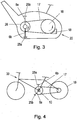
- FIG. 3 and FIG. 4 each show an application of the crank bearing 10 in a training device 20 and a bicycle 30.
- a training device 20 shown as a bicycle ergometer.
- the forces applied by the training person forces on the pedals 25a and 25b and the cranks 6a and 6b to the inner shaft 2 and the outer shaft 3 are transmitted.
- Via a traction mechanism 17, two attached to the shafts 2 and 3 pulleys 26 a and 26 b and running thereon belt the angular velocity and torque is transmitted to a flywheel 16.
- a brake 18 for example: a magnetic brake, an adjustable torque and thereby initiated by the training person to overcome resistance.
- FIG. 4 An application of the crank bearing 10 is in Fig. 4 shown.
- Fig. 4 showed a bicycle 30 with the inventive crank bearing 10 and attached cranks 6a and 6b.
- Pedals 25a and 25b are attached to the cranks.
- the power transmission of the forces applied to the pedals 25a and 25b forces via the cranks 6a and 6b to the inner shaft 2 and the outer shaft 3.
- a traction mechanism 17, here chain wheels with chains the torque of the inner shaft 2 and the outer shaft 3 to an energy-dissipating element 16, in this embodiment, a drive wheel 19, transmitted and discharged.
- a training device 20 or bicycle 30 may be implemented, in which the force is transmitted to the cranks 6a and 6b and the inner shaft 2 or outer shaft 3 instead of with pedals 25a and 25b, the power transmission via manuals, hand cranks.
- cranks 6a and 6b may be coupled to each other depending on rotation.
- the angular offset of the inner shaft 2 is limited to the outer shaft 3 at a relative angular offset between 90 ° and 180 ° and the inner shaft 2 is taken by the outer shaft 3, for example via an extension.
- a power transmission between the cranks 6a and 6b and the attached pedals or manuals can be effected to assist persons in the rehabilitation and to harmonize the movement of the extremities.
- the bearings 4 and 5 of in Fig. 1 and Fig. 2 described embodiment may alternatively to the deep groove ball bearings 4a; 4b and 5a; 5b may also be performed by other types of bearings, such as slide bearings or other roller bearings, such as tapered or tapered roller bearings or combinations of individual bearing shapes.
Landscapes
- Engineering & Computer Science (AREA)
- Mechanical Engineering (AREA)
- Chemical & Material Sciences (AREA)
- Combustion & Propulsion (AREA)
- Transportation (AREA)
- Shafts, Cranks, Connecting Bars, And Related Bearings (AREA)
- Health & Medical Sciences (AREA)
- Cardiology (AREA)
- Vascular Medicine (AREA)
- General Health & Medical Sciences (AREA)
- Physical Education & Sports Medicine (AREA)
- Motorcycle And Bicycle Frame (AREA)
- Support Of The Bearing (AREA)
- Rolling Contact Bearings (AREA)
Description
- Die Erfindung betrifft ein Trainingsgerät gemäß dem Oberbegriff des Anspruchs 1.
- Aus dem Stand der Technik sind Kurbellager bekannt deren Kurbeln voneinander unabhängig drehbar gelagert sind. Die Kurbeln sind dabei jeweils auf einem separaten am Rahmen eines Trainingsgerätes oder Fahrzeuges befestigten Lagerzapfen gelagert. Die Lagerungen sind dabei sehr breit um die Kräfte in einer Loslager/Festlager Kombination aufnehmen zu können. Dadurch ergibt sich eine sehr große Bauweise die den Abstand der an den Kurbeln befestigten Pedale deutlich erhöht, mit dem Nachteil, dass die Verbauten Kurbellager meist sehr massiv und vor allem breit sind. Die an den Kurbelarmen angebrachten Pedale weisen daher einen großen Abstand zueinander auf und verändern den Hebelarm und die Druck-Kinematik in den Extremitäten der Nutzer. Dies führt dazu, dass Personen mit Gelenksproblemen Trainingsgeräte mit entkoppelten Kurbeln diese Geräte nicht Nutzen können bzw. gesunde Personen eine erhöhte Belastung ausgesetzt sind, die negative Auswirkungen auf den Bewegungsapparat haben kann.
- Weiter ist aus der
WO 2002/00305 A1 - Aufgabe der Erfindung ist es daher ein schmales, klein bauendes Kurbellager mit zwei entkoppelten Kurbeln bereit zu stellen.
- Die Erfindung löst diese Aufgabe bei einem Trainingsgerät der eingangs genannten Art mit den im Kennzeichen des Patentanspruchs 1 angegebenen Merkmalen. Es ist erfindungsgemäß vorgesehen, dass das Kurbellager einen Doppellagerbock mit einer Ausnehmung, eine Außenwelle mit einer zentralen Ausnehmung, wobei die Außenwelle in der Ausnehmung des Doppellagerbocks mittels einer ersten Lagerung gelagert ist, und eine Innenwelle, die mittels einer zweiten Lagerung in der Ausnehmung der Außenwelle gelagert ist, umfasst, wobei die Innenwelle, die Außenwelle und die Ausnehmung des Doppellagerbocks koaxial angeordnet sind und eine gemeinsame Drehachse aufweisen.
- Die Lagerung der Innenwelle in der Außenwelle mit dem Doppellagerbock ermöglicht es den Abstand der einzelnen Lagerstellen breit auszuführen, um eine stabile und steife Befestigung der Kurbeln gegenüber dem Rahmen oder einem Gestell zu erreichen und gleichzeitig eine schmale Bauweise zu ermöglichen. Dadurch eignet sich der Einbau des Kurbellager besonders gut in Trainingsgeräten für die Rehabilitation in einer physikalischen Therapie und erreicht leichtere Fahrzeuge bei unabhängiger Verdrehbarkeit der Kurbeln.
- Weitere vorteilhafte Ausgestaltungen der Trainingsgeräte werden in den Ansprüchen der abhängigen Merkmale beschrieben.
- Um die an die Wellen eingeleiteten Kräfte und Drehmomente auf andere Elemente übertragen zu können ist vorgesehen, dass die Innenwelle und/oder die Außenwelle mit einem oder mehreren koaxialen, kraftübertragenden Elementen, insbesondere Kettenrädern und Riemenscheiben, kraftübertragend verbunden sind.
- Um die Wellen in Bewegung zu setzen und Kräfte bzw. Drehmomente in die Wellen einzuleiten ist vorgesehen, dass die Innenwelle mit einer ersten Kurbel verbunden ist und die Außenwelle mit einer axial gegenüberliegenden zweiten Kurbel verbunden ist, wobei die Kurbeln an gegenüberliegenden Außenflächen der Wellen angeordnet sind.
- Eine Übertragung von Drehmomenten und Kräften von einer Kurbel auf die andere ab einem bestimmten Winkelversatz kann erreicht werden, indem die Innenwelle und die Außenwelle rotationsabhängig gekoppelt sind, wobei die beiden Kurbeln mit einem relativen Winkelversatz, von zwischen 90° und 180°gegeneinender versetzt sind.
- Eine einfache Einleitung von Kräften in die Kurbeln sieht vor, dass an der ersten Kurbel und der zweiten Kurbel Pedale, insbesondere Fahrradpedale oder Handpedale, befestigt sind.
- Die Lagerung der Wellen ineinander bzw. im Doppellagerbock kann besonders reibungsarm und dadurch verlustarm erfolgen, wenn die erste und die zweite Lagerung als Radiallager, insbesondere als Lagerung mit Rillenkugellagern oder Gleitlagern, ausgebildet sind.
- Die Verkippbarkeit der Wellen ineinander und im Doppellagerbock wird reduziert, wenn die erste Lagerung und die zweite Lagerung jeweils zumindest zwei Lagerstellen aufweisen.
- Um den Einbau der Wellen ineinander und der Lager zu erleichtern ist vorgesehen, dass die Lagerstellen der ersten Lagerung und der zweiten Lagerung mit unterschiedlichem radialem Abstand von der Drehachse in einer oder mehrere zur Drehachse senkrecht stehenden Ebene angeordnet sind.
- Ein besonders schmales Kurbellager wird erreicht, indem die Lagerabstände der Lagerstellen der Lagerungen zwischen 5 cm und 20 cm betragen und/oder dass die Breite des Kurbellagers zwischen 5 cm und 20 cm beträgt.
- Eine Verwendung des Kurbellagers in einem Trainingsgerät sieht vor, dass ein Trainingsgerät, insbesondere ein Fahrradergometer, ein erfindungsgemäßes Kurbellager, sowie Elemente zur Krafteinleitung, insbesondere Pedale oder Manuale, umfasst.
- Ein besonders effizientes Trainingsgerät mit einem erfindungsgemäßen Kurbellager kann erzeugt werden, wenn die kraftübertragenden Elemente über Getriebe, insbesondere Zugmittelgetriebe, mit mindestens einem energieabführendem Element, insbesondere ein Schwungrad mit Magnetbremse und/oder einem energiezuführenden Element, insbesondere einem Motor, energieübertragend verbunden sind.
- Ein Fahrzeug mit unabhängig drehbaren Kurbelarmen kann bereitgestellt werden, wenn das Fahrzeug, insbesondere Fahrrad, ein erfindungsgemäßes Kurbellager, sowie Elemente zur Krafteinleitung, insbesondere Pedale oder Manuale, umfasst.
- Ein Fahrzeug mit einer vorteilhaften Übersetzung kann bereitgestellt werden, indem die kraftübertragenden Elemente über Getriebe, insbesondere Zugmittelgetriebe, mit mindestens einem energieabführendem Element, insbesondere mit einem Antriebsrad, verbunden sind.
- Weitere Vorteile und Ausgestaltungen ergeben sich aus der Beschreibung und den beiliegenden Zeichnungen.
- Eine bevorzugte Ausführungsform der Erfindung ist in den Zeichnungen
Fig. 1 bis Fig. 4 schematisch dargestellt und wird im Folgenden unter Bezugnahme auf die Zeichnungen beispielsweise beschrieben. - Es zeigen schematisch
- Fig. 1
- ein Kurbellager in Frontansicht,
- Fig. 2
- ein Kurbellager im Vollschnitt A-A,
- Fig. 3
- ein Fahrradergometer mit erfindungsgemäßem Kurbellager und
- Fig. 4
- ein Fahrrad mit erfindungsgemäßem Kurbellager.
-
Fig. 1 zeigt eine Frontansicht eines erfindungsgemäßen Kurbellagers 10 mit einem Doppellagerbock 1. Der Doppellagerbock 1 ist in stehender Form ausgeführt. Der Doppellagerbock 1 umfasst zwei Lagerdeckel 7a und 7b (Fig. 2 ), die durch Lagerschrauben 8 an dem Doppellagerbock 1 befestigt sind. Weiters zeigtFig. 1 eine Innenwelle 2 mit Bohrungen 21 an einem Flansch 22 zur Montage von Kurbeln 6a und 6b. - Eine erfindungsgemäße Ausführung des Kurbellagers 10 zeigt
Fig. 2 in einer Schnittansicht entlang der Achsen A-A (Fig. 1 ). Eine Außenwelle 3 ist über eine Lagerung 4, in einer Ausnehmung 11 des Doppellagerbocks 1, mit dem Doppellagerbock 1 des Kurbellagers 10 gelagert. Dabei sind die Rillenkugellager 4a und 4b an einer Wellenschulter 24 der Außenwelle 3 abgestützt und mit den Lagerdeckeln 7a und 7b schwimmend gelagert. Die Lagerdeckel 7a und 7b stützen die Außenringe der Rillenkugellagerlager 4a und 4b ab und über Schrauben 8 (Fig. 1 ) wird die Lagerung 4 vorgespannt wodurch die Außenwelle 3 axial gesichert ist. Die Innenwelle 2 ist hier als Vollwelle ausgebildet und besitzt an einer der Stirnseiten einen Flansch 22. Die Lagerung 5 der Innenwelle 2 in der Ausnehmung 31 der Außenwelle 3 ist durch zwei Radiallager, hier Rillenkugellager 5a und 5b, ausgeführt. Die Rillenkugellager 5a und 5b sind über eine Wellenschulter 13 der Innenwelle 2, die Außenwelle 3, eine Distanzhülse 14, zwei Sicherungsringe 9a und 9b und eine Wellenschulter 25 der Außenwelle 3 schwimmend gelagert. Dadurch ist die Innenwelle 2 relativ zur Außenwelle 3 in axialer Richtung gesichert. Durch die Lagerung 5 der Innenwelle 2 zusammen mit der Lagerung 4 der Außenwelle 3 im Doppellagerbock 1 können die Axial- und Radialkräfte aufgenommen werden und eine Rotation mit unterschiedlichen Winkelgeschwindigkeiten, der beiden Wellen 2 und 3, ermöglicht werden. Die Lagerstellen der ersten Lagerung 4 und der zweiten Lagerung 5 sind im unterschiedlichem radialen Abstand von der Drehachse 23 gesehen übereinander angeordnet. Der Lagerabstand, der Abstand zwischen den Lagerstellen der Lagerungen 4 und 5, ist zwischen 5cm und 20 cm und in dieser Ausführungsform 12 cm- Das Kurbellager besitz dabei eine Breite zwischen 5 cm und 20 cm und in dieser Ausführungsform eine Breite von 15 cm. -
Fig. 3 und Fig. 4 zeigen jeweils eine Anwendung des Kurbellagers 10 in einem Trainingsgerät 20 bzw. einem Fahrrad 30. InFig. 3 ist ein Trainingsgerät 20 als Fahrradergometer dargestellt. Dabei werden die von der Trainingsperson aufgebrachten Kräfte über die Pedale 25a und 25b und die Kurbeln 6a und 6b an die Innenwelle 2 bzw. die Außenwelle 3 übertragen. Über ein Zugmittelgetriebe 17, zwei an den Wellen 2 und 3 befestigte Riemenscheiben 26a und 26b und darauf laufenden Riemen, wird die Winkelgeschwindigkeit und das Drehmoment an ein Schwungrad 16 übertragen. Auf das Schwungrad 16 wird mittels einer Bremse 18, z.B.: einer Magnetbremse, ein einstellbares Drehmoment aufgebracht und dadurch ein durch die Trainingsperson zu überwindender Wiederstand eingeleitet. - Eine Anwendung des Kurbellagers 10 ist in
Fig. 4 dargestellt.Fig. 4 zeigte ein Fahrrad 30 mit dem erfindungsgemäßem Kurbellager 10 und daran befestigten Kurbeln 6a und 6b. An den Kurbeln sind Pedale 25a und 25b befestigt. Die Kraftübertragung der an den Pedalen 25a und 25b eingeleiteten Kräfte erfolgt über die Kurbeln 6a und 6b an die Innenwelle 2 und die Außenwelle 3. Über ein Zugmittelgetriebe 17, hier Kettenräder mit Ketten wird das Drehmoment der Innenwelle 2 und der Außenwelle 3 an ein energieabführendes Element 16, bei dieser Ausführungsform ein Antriebsrad 19, übertragen und abgeführt. - Alternativ kann ein Trainingsgerät 20 oder Fahrrad 30 ausgeführt sein, bei dem die Krafteinleitung in die Kurbeln 6a und 6b und die Innenwelle 2 bzw. Außenwelle 3 anstelle von mit Pedalen 25a und 25b die Kraftübertragung über Manuale, Handkurbeln, erfolgt.
- Anstelle der Riemenscheiben 26a und 26b können auch Kettenräder mit Ketten zur Kraftübertragung zwischen den Wellen 2 und 3 und energieabführenden Elementen 16, wie einem Schwungrad oder einem Antriebsrad 19, an der Innenwelle 2 und Außenwelle 3 ausgeführt sein. Ebenso können die Kurbeln 6a und 6b miteinander rotationsabhängig gekoppelt sein. Dabei ist zum Beispiel der Winkelversatz der Innenwelle 2 mit der Außenwelle 3 bei einem relativen Winkelversatz zwischen 90° und 180° begrenzt und die Innenwelle 2 wird durch die Außenwelle 3, zum Beispiel über einen Fortsatz, mitgenommen. Dadurch kann eine Kraftübertragung zwischen den Kurbeln 6a und 6b und den daran befestigten Pedalen oder Manualen bewirkt werden, um Personen in der Rehabilitation zu unterstützen und den Bewegungsablauf der Extremitäten zu harmonisieren.
- Die Lagerungen 4 und 5 der in
Fig. 1 und Fig. 2 beschriebenen Ausführungsform können alternativ zu den Rillenkugellager 4a; 4b und 5a; 5b auch durch andere Lagerformen, wie Gleitlager oder andere Wälzlager, wie Tonen - oder Kegelrollenlager oder aus Kombinationen einzelner Lagerformen, ausgeführt werden.
Claims (10)
- Trainingsgerät (20), insbesondere Fahrradergometer, umfassend ein Kurbellager (10) mit voneinander unabhängig drehbaren Kurbeln,- wobei das Trainingsgerät (20) Elemente zur Krafteinleitung (25a, 25b), insbesondere Pedale oder Manuale umfasst,- und wobei die kraftübertragenden Elemente (26) über Getriebe mit mindestens einem energieabführendem Element (16), und/oder einem energiezuführenden Element energieübertragend verbunden sind,dadurch gekennzeichnet, daß- ein Doppellagerbock (1) mit einer Ausnehmung (11), eine Außenwelle (3) mit einer zentralen Ausnehmung (31), wobei die Außenwelle (3) in der Ausnehmung (11) des Doppellagerbocks (1) mittels einer ersten Lagerung (4) gelagert ist, und eine Innenwelle (2), die mittels einer zweiten Lagerung (5) in der Ausnehmung (31) der Außenwelle (3) gelagert ist, vorgesehen ist, wobei die Innenwelle (2), die Außenwelle (3) und die Ausnehmung (11) des Doppellagerbocks (1) koaxial angeordnet sind und eine gemeinsame Drehachse (23) aufweisen,- wobei die Innenwelle (2) und/oder die Außenwelle (3) mit einem oder mehreren koaxialen, kraftübertragenden Elementen (26), insbesondere Kettenrädern und Riemenscheiben, kraftübertragend verbunden sind.
- Trainingsgerät (20) nach Anspruch 1, dadurch gekennzeichnet, dass die Innenwelle (2) mit einer ersten Kurbel (6a) verbunden ist und die Außenwelle (3) mit einer axial gegenüberliegenden zweiten Kurbel (6b) verbunden ist, wobei die Kurbeln (6a,6b) an gegenüberliegenden Außenflächen der Wellen (2, 3) angeordnet sind.
- Trainingsgerät (20) nach Anspruch 2, dadurch gekennzeichnet, dass die Innenwelle (2) und die Außenwelle (3) rotationsabhängig gekoppelt sind, wobei die beiden Kurbeln (6a, 6b) mit einem relativen Winkelversatz, von zwischen 90° und 180° gegeneinender versetzt sind.
- Trainingsgerät (20) nach einem der Ansprüche 2 oder 3, dadurch gekennzeichnet, dass an der ersten Kurbel (6a) und der zweiten Kurbel (6b) Pedale (25a, 25b), insbesondere Fahrradpedale (25a, 25b) oder Handpedale, befestigt sind.
- Trainingsgerät (20) nach einem der Ansprüche 1 bis 4, dadurch gekennzeichnet, dass die erste und die zweite Lagerung (4, 5) als Radiallager, insbesondere als Lagerung mit Rillenkugellagern (4a, 4b; 5a, 5b) oder Gleitlagern, ausgebildet sind.
- Trainingsgerät (20) nach einem der Ansprüche 1 bis 5, dadurch gekennzeichnet, dass die erste Lagerung (4) und die zweite Lagerung (5) jeweils zumindest zwei Lagerstellen aufweisen.
- Trainingsgerät (20) nach einem der Ansprüche 1 bis 6, dadurch gekennzeichnet, dass die Lagerstellen der ersten Lagerung (4) und der zweiten Lagerung (5) mit unterschiedlichem radialem Abstand von der Drehachse (23) in einer oder mehrere zur Drehachse (23) senkrecht stehenden Ebene angeordnet sind.
- Trainingsgerät (20) nach einem der Ansprüche 1 bis 7, dadurch gekennzeichnet, dass die Lagerabstände der Lagerstellen der Lagerungen (4, 5) zwischen 5 cm und 20 cm betragen (4; 5) und/oder dass die Breite des Kurbellagers zwischen 5 cm und 20 cm beträgt.
- Trainingsgerät (20) nach einem der vorangehenden Ansprüche, dadurch gekennzeichnet, dass die kraftübertragenden Elemente (26a, 26b) über Zugmittelgetriebe (17), mit mindestens einem energieabführendem Element (16) energieübertragend verbunden sind.
- Trainingsgerät (20) nach einem der vorangehenden Ansprüche, dadurch gekennzeichnet, dass das mindestens einem energieabführendem Element (16) als Schwungrad (16) mit Magnetbremse (18) ausgebildet ist und/oder dass das energiezuführenden Element einen Motor umfasst.
Applications Claiming Priority (2)
| Application Number | Priority Date | Filing Date | Title |
|---|---|---|---|
| ATA50033/2013A AT513864B1 (de) | 2013-01-21 | 2013-01-21 | Trainingsgerät, insbesondere Fahrradergometer |
| PCT/AT2014/050018 WO2014110616A1 (de) | 2013-01-21 | 2014-01-20 | Kurbellager |
Publications (2)
| Publication Number | Publication Date |
|---|---|
| EP2945842A1 EP2945842A1 (de) | 2015-11-25 |
| EP2945842B1 true EP2945842B1 (de) | 2017-03-01 |
Family
ID=50158973
Family Applications (1)
| Application Number | Title | Priority Date | Filing Date |
|---|---|---|---|
| EP14706266.5A Not-in-force EP2945842B1 (de) | 2013-01-21 | 2014-01-20 | Trainingsgerät |
Country Status (3)
| Country | Link |
|---|---|
| EP (1) | EP2945842B1 (de) |
| AT (1) | AT513864B1 (de) |
| WO (1) | WO2014110616A1 (de) |
Citations (1)
| Publication number | Priority date | Publication date | Assignee | Title |
|---|---|---|---|---|
| WO2002000305A1 (de) * | 2000-06-27 | 2002-01-03 | Peter Vohryzka | Ergometer |
Family Cites Families (3)
| Publication number | Priority date | Publication date | Assignee | Title |
|---|---|---|---|---|
| WO1986005459A1 (fr) * | 1985-03-13 | 1986-09-25 | Sté Look | Pedalier pour byciclette ou engin de locomotion analogue |
| CN2122825U (zh) * | 1992-04-15 | 1992-11-25 | 徐模宏 | 自行车往复曲柄踏板 |
| US6085613A (en) * | 1995-12-07 | 2000-07-11 | Niculescu; Florin | Crankset with no neutral position |
-
2013
- 2013-01-21 AT ATA50033/2013A patent/AT513864B1/de not_active IP Right Cessation
-
2014
- 2014-01-20 WO PCT/AT2014/050018 patent/WO2014110616A1/de not_active Ceased
- 2014-01-20 EP EP14706266.5A patent/EP2945842B1/de not_active Not-in-force
Patent Citations (1)
| Publication number | Priority date | Publication date | Assignee | Title |
|---|---|---|---|---|
| WO2002000305A1 (de) * | 2000-06-27 | 2002-01-03 | Peter Vohryzka | Ergometer |
Also Published As
| Publication number | Publication date |
|---|---|
| WO2014110616A1 (de) | 2014-07-24 |
| AT513864A1 (de) | 2014-08-15 |
| EP2945842A1 (de) | 2015-11-25 |
| AT513864B1 (de) | 2015-04-15 |
Similar Documents
| Publication | Publication Date | Title |
|---|---|---|
| EP4228958B1 (de) | Antriebseinheit für ein gleichzeitig aus menschlicher muskelkraft und elektromotorisch antreibbares fortbewegungsmittel | |
| DE60205460T2 (de) | Planetengetriebe und dessen verwendung | |
| DE202010008467U1 (de) | Entkoppelbarer Aktuator, insbesondere mit elektromechanischem Antrieb | |
| EP2669549B1 (de) | Fahrradgetriebe | |
| DE102022125866A1 (de) | Vorrichtung zur Drehmomentübertragung, Vorrichtung zur elektrischen Unterstützung und dazugehöriges Zweirad | |
| DE102016201227A1 (de) | Lenkanordnung | |
| AT4425U1 (de) | Ergometer | |
| EP3406511B1 (de) | Elektrischer fahrrad-tretkurbelantrieb | |
| EP2502819A1 (de) | Elektrischer Hilfsantreib für Fahrräder | |
| EP3986776B1 (de) | Bremseinheit für ein fahrzeug, bremsvorrichtung mit der bremseinheit sowie fahrzeug mit der bremseinheit und/oder der bremsvorrichtung | |
| DE19737138C2 (de) | Kabel-Lenkvorrichtung | |
| AT513864B1 (de) | Trainingsgerät, insbesondere Fahrradergometer | |
| EP1749156B1 (de) | Epyzyklisches rädergetriebe zur änderung der winkelgeschwindigkeit zwischen zwei wellen sowie fahrrad, versehen mit einem solchen epyzyklischen rädergetriebe | |
| DE102019205702A1 (de) | Lenksäulenmodul für ein Steer-by-wire Lenksystem eines Kraftfahrzeuges, insbesondere mit einem für eine ankoppelbare Sicherheitslenksäule frei zugänglichen Wellenende | |
| EP2298636B1 (de) | Getriebeanordnung für ein mit einem Hilfsantrieb ausgestattetes Fahrrad | |
| EP1776988B1 (de) | Antriebseinheit | |
| DE102016220853A1 (de) | Kettentrieb für ein schaltbares Kettenfahrzeug | |
| DE102024128567B4 (de) | Lenksystem für ein Fahrzeug | |
| EP2338780B1 (de) | Mit Muskelkraft betriebenes Fahrzeug, insbesondere Landfahrzeug | |
| DE102024112067B4 (de) | Antriebsvorrichtung für ein Fahrrad mit einem stufenlos verstellbaren Getriebe | |
| EP1666765A1 (de) | Getriebe | |
| DE19715555B4 (de) | Trainingsgerät zur Bewegungstherapie | |
| DE9311547U1 (de) | Fahrgerät mit Tretkurbelorgan | |
| DE102024134240A1 (de) | Antriebseinheit für ein Fahrrad und Fahrrad mit einer solchen Antriebseinheit | |
| DE102024112070A1 (de) | Antriebsvorrichtung für ein Fahrrad mit einem stufenlos verstellbaren Getriebe |
Legal Events
| Date | Code | Title | Description |
|---|---|---|---|
| PUAI | Public reference made under article 153(3) epc to a published international application that has entered the european phase |
Free format text: ORIGINAL CODE: 0009012 |
|
| 17P | Request for examination filed |
Effective date: 20150714 |
|
| AK | Designated contracting states |
Kind code of ref document: A1 Designated state(s): AL AT BE BG CH CY CZ DE DK EE ES FI FR GB GR HR HU IE IS IT LI LT LU LV MC MK MT NL NO PL PT RO RS SE SI SK SM TR |
|
| AX | Request for extension of the european patent |
Extension state: BA ME |
|
| DAX | Request for extension of the european patent (deleted) | ||
| GRAP | Despatch of communication of intention to grant a patent |
Free format text: ORIGINAL CODE: EPIDOSNIGR1 |
|
| INTG | Intention to grant announced |
Effective date: 20160901 |
|
| GRAS | Grant fee paid |
Free format text: ORIGINAL CODE: EPIDOSNIGR3 |
|
| STAA | Information on the status of an ep patent application or granted ep patent |
Free format text: STATUS: GRANT OF PATENT IS INTENDED |
|
| GRAA | (expected) grant |
Free format text: ORIGINAL CODE: 0009210 |
|
| STAA | Information on the status of an ep patent application or granted ep patent |
Free format text: STATUS: THE PATENT HAS BEEN GRANTED |
|
| AK | Designated contracting states |
Kind code of ref document: B1 Designated state(s): AL AT BE BG CH CY CZ DE DK EE ES FI FR GB GR HR HU IE IS IT LI LT LU LV MC MK MT NL NO PL PT RO RS SE SI SK SM TR |
|
| REG | Reference to a national code |
Ref country code: GB Ref legal event code: FG4D Free format text: NOT ENGLISH |
|
| REG | Reference to a national code |
Ref country code: CH Ref legal event code: EP Ref country code: AT Ref legal event code: REF Ref document number: 870924 Country of ref document: AT Kind code of ref document: T Effective date: 20170315 |
|
| REG | Reference to a national code |
Ref country code: IE Ref legal event code: FG4D Free format text: LANGUAGE OF EP DOCUMENT: GERMAN |
|
| REG | Reference to a national code |
Ref country code: DE Ref legal event code: R096 Ref document number: 502014002837 Country of ref document: DE |
|
| REG | Reference to a national code |
Ref country code: NL Ref legal event code: MP Effective date: 20170301 |
|
| REG | Reference to a national code |
Ref country code: LT Ref legal event code: MG4D |
|
| PG25 | Lapsed in a contracting state [announced via postgrant information from national office to epo] |
Ref country code: GR Free format text: LAPSE BECAUSE OF FAILURE TO SUBMIT A TRANSLATION OF THE DESCRIPTION OR TO PAY THE FEE WITHIN THE PRESCRIBED TIME-LIMIT Effective date: 20170602 Ref country code: HR Free format text: LAPSE BECAUSE OF FAILURE TO SUBMIT A TRANSLATION OF THE DESCRIPTION OR TO PAY THE FEE WITHIN THE PRESCRIBED TIME-LIMIT Effective date: 20170301 Ref country code: LT Free format text: LAPSE BECAUSE OF FAILURE TO SUBMIT A TRANSLATION OF THE DESCRIPTION OR TO PAY THE FEE WITHIN THE PRESCRIBED TIME-LIMIT Effective date: 20170301 Ref country code: FI Free format text: LAPSE BECAUSE OF FAILURE TO SUBMIT A TRANSLATION OF THE DESCRIPTION OR TO PAY THE FEE WITHIN THE PRESCRIBED TIME-LIMIT Effective date: 20170301 Ref country code: NO Free format text: LAPSE BECAUSE OF FAILURE TO SUBMIT A TRANSLATION OF THE DESCRIPTION OR TO PAY THE FEE WITHIN THE PRESCRIBED TIME-LIMIT Effective date: 20170601 |
|
| PG25 | Lapsed in a contracting state [announced via postgrant information from national office to epo] |
Ref country code: ES Free format text: LAPSE BECAUSE OF FAILURE TO SUBMIT A TRANSLATION OF THE DESCRIPTION OR TO PAY THE FEE WITHIN THE PRESCRIBED TIME-LIMIT Effective date: 20170301 Ref country code: BG Free format text: LAPSE BECAUSE OF FAILURE TO SUBMIT A TRANSLATION OF THE DESCRIPTION OR TO PAY THE FEE WITHIN THE PRESCRIBED TIME-LIMIT Effective date: 20170601 Ref country code: SE Free format text: LAPSE BECAUSE OF FAILURE TO SUBMIT A TRANSLATION OF THE DESCRIPTION OR TO PAY THE FEE WITHIN THE PRESCRIBED TIME-LIMIT Effective date: 20170301 Ref country code: RS Free format text: LAPSE BECAUSE OF FAILURE TO SUBMIT A TRANSLATION OF THE DESCRIPTION OR TO PAY THE FEE WITHIN THE PRESCRIBED TIME-LIMIT Effective date: 20170301 Ref country code: LV Free format text: LAPSE BECAUSE OF FAILURE TO SUBMIT A TRANSLATION OF THE DESCRIPTION OR TO PAY THE FEE WITHIN THE PRESCRIBED TIME-LIMIT Effective date: 20170301 |
|
| PG25 | Lapsed in a contracting state [announced via postgrant information from national office to epo] |
Ref country code: NL Free format text: LAPSE BECAUSE OF FAILURE TO SUBMIT A TRANSLATION OF THE DESCRIPTION OR TO PAY THE FEE WITHIN THE PRESCRIBED TIME-LIMIT Effective date: 20170301 |
|
| PG25 | Lapsed in a contracting state [announced via postgrant information from national office to epo] |
Ref country code: CZ Free format text: LAPSE BECAUSE OF FAILURE TO SUBMIT A TRANSLATION OF THE DESCRIPTION OR TO PAY THE FEE WITHIN THE PRESCRIBED TIME-LIMIT Effective date: 20170301 Ref country code: SK Free format text: LAPSE BECAUSE OF FAILURE TO SUBMIT A TRANSLATION OF THE DESCRIPTION OR TO PAY THE FEE WITHIN THE PRESCRIBED TIME-LIMIT Effective date: 20170301 Ref country code: EE Free format text: LAPSE BECAUSE OF FAILURE TO SUBMIT A TRANSLATION OF THE DESCRIPTION OR TO PAY THE FEE WITHIN THE PRESCRIBED TIME-LIMIT Effective date: 20170301 Ref country code: RO Free format text: LAPSE BECAUSE OF FAILURE TO SUBMIT A TRANSLATION OF THE DESCRIPTION OR TO PAY THE FEE WITHIN THE PRESCRIBED TIME-LIMIT Effective date: 20170301 |
|
| PG25 | Lapsed in a contracting state [announced via postgrant information from national office to epo] |
Ref country code: SM Free format text: LAPSE BECAUSE OF FAILURE TO SUBMIT A TRANSLATION OF THE DESCRIPTION OR TO PAY THE FEE WITHIN THE PRESCRIBED TIME-LIMIT Effective date: 20170301 Ref country code: PL Free format text: LAPSE BECAUSE OF FAILURE TO SUBMIT A TRANSLATION OF THE DESCRIPTION OR TO PAY THE FEE WITHIN THE PRESCRIBED TIME-LIMIT Effective date: 20170301 Ref country code: PT Free format text: LAPSE BECAUSE OF FAILURE TO SUBMIT A TRANSLATION OF THE DESCRIPTION OR TO PAY THE FEE WITHIN THE PRESCRIBED TIME-LIMIT Effective date: 20170703 Ref country code: IS Free format text: LAPSE BECAUSE OF FAILURE TO SUBMIT A TRANSLATION OF THE DESCRIPTION OR TO PAY THE FEE WITHIN THE PRESCRIBED TIME-LIMIT Effective date: 20170701 |
|
| REG | Reference to a national code |
Ref country code: DE Ref legal event code: R097 Ref document number: 502014002837 Country of ref document: DE |
|
| PLBE | No opposition filed within time limit |
Free format text: ORIGINAL CODE: 0009261 |
|
| STAA | Information on the status of an ep patent application or granted ep patent |
Free format text: STATUS: NO OPPOSITION FILED WITHIN TIME LIMIT |
|
| PG25 | Lapsed in a contracting state [announced via postgrant information from national office to epo] |
Ref country code: DK Free format text: LAPSE BECAUSE OF FAILURE TO SUBMIT A TRANSLATION OF THE DESCRIPTION OR TO PAY THE FEE WITHIN THE PRESCRIBED TIME-LIMIT Effective date: 20170301 |
|
| 26N | No opposition filed |
Effective date: 20171204 |
|
| PG25 | Lapsed in a contracting state [announced via postgrant information from national office to epo] |
Ref country code: SI Free format text: LAPSE BECAUSE OF FAILURE TO SUBMIT A TRANSLATION OF THE DESCRIPTION OR TO PAY THE FEE WITHIN THE PRESCRIBED TIME-LIMIT Effective date: 20170301 Ref country code: IT Free format text: LAPSE BECAUSE OF FAILURE TO SUBMIT A TRANSLATION OF THE DESCRIPTION OR TO PAY THE FEE WITHIN THE PRESCRIBED TIME-LIMIT Effective date: 20170301 |
|
| REG | Reference to a national code |
Ref country code: DE Ref legal event code: R119 Ref document number: 502014002837 Country of ref document: DE |
|
| REG | Reference to a national code |
Ref country code: CH Ref legal event code: PL |
|
| GBPC | Gb: european patent ceased through non-payment of renewal fee |
Effective date: 20180120 |
|
| PG25 | Lapsed in a contracting state [announced via postgrant information from national office to epo] |
Ref country code: MT Free format text: LAPSE BECAUSE OF FAILURE TO SUBMIT A TRANSLATION OF THE DESCRIPTION OR TO PAY THE FEE WITHIN THE PRESCRIBED TIME-LIMIT Effective date: 20170301 |
|
| PG25 | Lapsed in a contracting state [announced via postgrant information from national office to epo] |
Ref country code: DE Free format text: LAPSE BECAUSE OF NON-PAYMENT OF DUE FEES Effective date: 20180801 Ref country code: FR Free format text: LAPSE BECAUSE OF NON-PAYMENT OF DUE FEES Effective date: 20180131 Ref country code: LU Free format text: LAPSE BECAUSE OF NON-PAYMENT OF DUE FEES Effective date: 20180120 |
|
| REG | Reference to a national code |
Ref country code: IE Ref legal event code: MM4A |
|
| REG | Reference to a national code |
Ref country code: FR Ref legal event code: ST Effective date: 20180928 |
|
| REG | Reference to a national code |
Ref country code: BE Ref legal event code: MM Effective date: 20180131 |
|
| PG25 | Lapsed in a contracting state [announced via postgrant information from national office to epo] |
Ref country code: CH Free format text: LAPSE BECAUSE OF NON-PAYMENT OF DUE FEES Effective date: 20180131 Ref country code: LI Free format text: LAPSE BECAUSE OF NON-PAYMENT OF DUE FEES Effective date: 20180131 Ref country code: GB Free format text: LAPSE BECAUSE OF NON-PAYMENT OF DUE FEES Effective date: 20180120 Ref country code: BE Free format text: LAPSE BECAUSE OF NON-PAYMENT OF DUE FEES Effective date: 20180131 |
|
| PG25 | Lapsed in a contracting state [announced via postgrant information from national office to epo] |
Ref country code: IE Free format text: LAPSE BECAUSE OF NON-PAYMENT OF DUE FEES Effective date: 20180120 |
|
| PG25 | Lapsed in a contracting state [announced via postgrant information from national office to epo] |
Ref country code: MC Free format text: LAPSE BECAUSE OF FAILURE TO SUBMIT A TRANSLATION OF THE DESCRIPTION OR TO PAY THE FEE WITHIN THE PRESCRIBED TIME-LIMIT Effective date: 20170301 |
|
| REG | Reference to a national code |
Ref country code: AT Ref legal event code: MM01 Ref document number: 870924 Country of ref document: AT Kind code of ref document: T Effective date: 20190120 |
|
| PG25 | Lapsed in a contracting state [announced via postgrant information from national office to epo] |
Ref country code: TR Free format text: LAPSE BECAUSE OF FAILURE TO SUBMIT A TRANSLATION OF THE DESCRIPTION OR TO PAY THE FEE WITHIN THE PRESCRIBED TIME-LIMIT Effective date: 20170301 |
|
| PG25 | Lapsed in a contracting state [announced via postgrant information from national office to epo] |
Ref country code: AT Free format text: LAPSE BECAUSE OF NON-PAYMENT OF DUE FEES Effective date: 20190120 |
|
| PG25 | Lapsed in a contracting state [announced via postgrant information from national office to epo] |
Ref country code: CY Free format text: LAPSE BECAUSE OF FAILURE TO SUBMIT A TRANSLATION OF THE DESCRIPTION OR TO PAY THE FEE WITHIN THE PRESCRIBED TIME-LIMIT Effective date: 20170301 Ref country code: MK Free format text: LAPSE BECAUSE OF NON-PAYMENT OF DUE FEES Effective date: 20170301 Ref country code: HU Free format text: LAPSE BECAUSE OF FAILURE TO SUBMIT A TRANSLATION OF THE DESCRIPTION OR TO PAY THE FEE WITHIN THE PRESCRIBED TIME-LIMIT; INVALID AB INITIO Effective date: 20140120 |
|
| PG25 | Lapsed in a contracting state [announced via postgrant information from national office to epo] |
Ref country code: AL Free format text: LAPSE BECAUSE OF FAILURE TO SUBMIT A TRANSLATION OF THE DESCRIPTION OR TO PAY THE FEE WITHIN THE PRESCRIBED TIME-LIMIT Effective date: 20170301 |