EP2945790B1 - An integrated apparatus and method for continuous ion exchange membrane casting and processing - Google Patents
An integrated apparatus and method for continuous ion exchange membrane casting and processing Download PDFInfo
- Publication number
- EP2945790B1 EP2945790B1 EP13702149.9A EP13702149A EP2945790B1 EP 2945790 B1 EP2945790 B1 EP 2945790B1 EP 13702149 A EP13702149 A EP 13702149A EP 2945790 B1 EP2945790 B1 EP 2945790B1
- Authority
- EP
- European Patent Office
- Prior art keywords
- membrane
- section
- processing
- dye
- contrast
- Prior art date
- Legal status (The legal status is an assumption and is not a legal conclusion. Google has not performed a legal analysis and makes no representation as to the accuracy of the status listed.)
- Not-in-force
Links
- 238000000034 method Methods 0.000 title claims description 16
- 238000005266 casting Methods 0.000 title claims description 13
- 239000003014 ion exchange membrane Substances 0.000 title description 4
- 239000012528 membrane Substances 0.000 claims description 172
- 238000000605 extraction Methods 0.000 claims description 50
- 239000007788 liquid Substances 0.000 claims description 43
- 239000000758 substrate Substances 0.000 claims description 41
- 239000002243 precursor Substances 0.000 claims description 32
- 230000003750 conditioning effect Effects 0.000 claims description 28
- 239000002872 contrast media Substances 0.000 claims description 23
- 238000012360 testing method Methods 0.000 claims description 21
- 238000005520 cutting process Methods 0.000 claims description 14
- 238000004519 manufacturing process Methods 0.000 claims description 10
- 238000005406 washing Methods 0.000 claims description 8
- 238000007689 inspection Methods 0.000 claims description 3
- 239000000975 dye Substances 0.000 description 40
- XLYOFNOQVPJJNP-UHFFFAOYSA-N water Substances O XLYOFNOQVPJJNP-UHFFFAOYSA-N 0.000 description 32
- 239000012530 fluid Substances 0.000 description 20
- 239000000243 solution Substances 0.000 description 19
- 238000007789 sealing Methods 0.000 description 12
- 238000006116 polymerization reaction Methods 0.000 description 7
- -1 polypropylene Polymers 0.000 description 7
- 238000003860 storage Methods 0.000 description 7
- QTBSBXVTEAMEQO-UHFFFAOYSA-N Acetic acid Chemical compound CC(O)=O QTBSBXVTEAMEQO-UHFFFAOYSA-N 0.000 description 6
- KRKNYBCHXYNGOX-UHFFFAOYSA-N citric acid Chemical compound OC(=O)CC(O)(C(O)=O)CC(O)=O KRKNYBCHXYNGOX-UHFFFAOYSA-N 0.000 description 6
- 229920000642 polymer Polymers 0.000 description 6
- 238000009826 distribution Methods 0.000 description 5
- 239000000126 substance Substances 0.000 description 5
- 0 C*CCC1CC(*C2CCCC2)CCC1 Chemical compound C*CCC1CC(*C2CCCC2)CCC1 0.000 description 4
- 238000010586 diagram Methods 0.000 description 4
- 239000004744 fabric Substances 0.000 description 4
- 238000005086 pumping Methods 0.000 description 4
- DNIAPMSPPWPWGF-UHFFFAOYSA-N Propylene glycol Chemical compound CC(O)CO DNIAPMSPPWPWGF-UHFFFAOYSA-N 0.000 description 3
- 150000002500 ions Chemical class 0.000 description 3
- 239000000463 material Substances 0.000 description 3
- 238000002844 melting Methods 0.000 description 3
- 230000008018 melting Effects 0.000 description 3
- 239000003505 polymerization initiator Substances 0.000 description 3
- 238000003825 pressing Methods 0.000 description 3
- 239000002904 solvent Substances 0.000 description 3
- 230000000007 visual effect Effects 0.000 description 3
- 238000009736 wetting Methods 0.000 description 3
- BVKZGUZCCUSVTD-UHFFFAOYSA-M Bicarbonate Chemical compound OC([O-])=O BVKZGUZCCUSVTD-UHFFFAOYSA-M 0.000 description 2
- KFZMGEQAYNKOFK-UHFFFAOYSA-N Isopropanol Chemical compound CC(C)O KFZMGEQAYNKOFK-UHFFFAOYSA-N 0.000 description 2
- LRHPLDYGYMQRHN-UHFFFAOYSA-N N-Butanol Chemical compound CCCCO LRHPLDYGYMQRHN-UHFFFAOYSA-N 0.000 description 2
- SECXISVLQFMRJM-UHFFFAOYSA-N N-Methylpyrrolidone Chemical compound CN1CCCC1=O SECXISVLQFMRJM-UHFFFAOYSA-N 0.000 description 2
- 239000004743 Polypropylene Substances 0.000 description 2
- FAPWRFPIFSIZLT-UHFFFAOYSA-M Sodium chloride Chemical compound [Na+].[Cl-] FAPWRFPIFSIZLT-UHFFFAOYSA-M 0.000 description 2
- 230000002378 acidificating effect Effects 0.000 description 2
- 239000000654 additive Substances 0.000 description 2
- 150000001298 alcohols Chemical class 0.000 description 2
- 150000001408 amides Chemical class 0.000 description 2
- 150000001412 amines Chemical class 0.000 description 2
- 238000006243 chemical reaction Methods 0.000 description 2
- 239000000356 contaminant Substances 0.000 description 2
- 239000003085 diluting agent Substances 0.000 description 2
- SZXQTJUDPRGNJN-UHFFFAOYSA-N dipropylene glycol Chemical compound OCCCOCCCO SZXQTJUDPRGNJN-UHFFFAOYSA-N 0.000 description 2
- 229940113120 dipropylene glycol Drugs 0.000 description 2
- 150000002148 esters Chemical class 0.000 description 2
- 150000002170 ethers Chemical class 0.000 description 2
- ZXEKIIBDNHEJCQ-UHFFFAOYSA-N isobutanol Chemical compound CC(C)CO ZXEKIIBDNHEJCQ-UHFFFAOYSA-N 0.000 description 2
- JVTAAEKCZFNVCJ-UHFFFAOYSA-N lactic acid Chemical compound CC(O)C(O)=O JVTAAEKCZFNVCJ-UHFFFAOYSA-N 0.000 description 2
- WMFOQBRAJBCJND-UHFFFAOYSA-M lithium hydroxide Inorganic materials [Li+].[OH-] WMFOQBRAJBCJND-UHFFFAOYSA-M 0.000 description 2
- 229910052751 metal Inorganic materials 0.000 description 2
- 239000002184 metal Substances 0.000 description 2
- 229920000728 polyester Polymers 0.000 description 2
- 229920001155 polypropylene Polymers 0.000 description 2
- BDERNNFJNOPAEC-UHFFFAOYSA-N propan-1-ol Chemical compound CCCO BDERNNFJNOPAEC-UHFFFAOYSA-N 0.000 description 2
- 230000005855 radiation Effects 0.000 description 2
- 239000007784 solid electrolyte Substances 0.000 description 2
- 238000003466 welding Methods 0.000 description 2
- OALHHIHQOFIMEF-UHFFFAOYSA-N 3',6'-dihydroxy-2',4',5',7'-tetraiodo-3h-spiro[2-benzofuran-1,9'-xanthene]-3-one Chemical compound O1C(=O)C2=CC=CC=C2C21C1=CC(I)=C(O)C(I)=C1OC1=C(I)C(O)=C(I)C=C21 OALHHIHQOFIMEF-UHFFFAOYSA-N 0.000 description 1
- RBTBFTRPCNLSDE-UHFFFAOYSA-N 3,7-bis(dimethylamino)phenothiazin-5-ium Chemical compound C1=CC(N(C)C)=CC2=[S+]C3=CC(N(C)C)=CC=C3N=C21 RBTBFTRPCNLSDE-UHFFFAOYSA-N 0.000 description 1
- CPELXLSAUQHCOX-UHFFFAOYSA-M Bromide Chemical compound [Br-] CPELXLSAUQHCOX-UHFFFAOYSA-M 0.000 description 1
- 229920003043 Cellulose fiber Polymers 0.000 description 1
- VEXZGXHMUGYJMC-UHFFFAOYSA-M Chloride anion Chemical compound [Cl-] VEXZGXHMUGYJMC-UHFFFAOYSA-M 0.000 description 1
- HBBGRARXTFLTSG-UHFFFAOYSA-N Lithium ion Chemical compound [Li+] HBBGRARXTFLTSG-UHFFFAOYSA-N 0.000 description 1
- 239000002253 acid Substances 0.000 description 1
- NIXOWILDQLNWCW-UHFFFAOYSA-N acrylic acid group Chemical group C(C=C)(=O)O NIXOWILDQLNWCW-UHFFFAOYSA-N 0.000 description 1
- QGZKDVFQNNGYKY-UHFFFAOYSA-O ammonium group Chemical group [NH4+] QGZKDVFQNNGYKY-UHFFFAOYSA-O 0.000 description 1
- 238000013459 approach Methods 0.000 description 1
- 239000007864 aqueous solution Substances 0.000 description 1
- 238000009835 boiling Methods 0.000 description 1
- ZCDOYSPFYFSLEW-UHFFFAOYSA-N chromate(2-) Chemical compound [O-][Cr]([O-])(=O)=O ZCDOYSPFYFSLEW-UHFFFAOYSA-N 0.000 description 1
- 150000001875 compounds Chemical class 0.000 description 1
- 238000010924 continuous production Methods 0.000 description 1
- 239000008367 deionised water Substances 0.000 description 1
- 230000001419 dependent effect Effects 0.000 description 1
- 239000012153 distilled water Substances 0.000 description 1
- 239000012154 double-distilled water Substances 0.000 description 1
- 238000011010 flushing procedure Methods 0.000 description 1
- 239000000446 fuel Substances 0.000 description 1
- 150000002334 glycols Chemical class 0.000 description 1
- 238000010438 heat treatment Methods 0.000 description 1
- 239000001257 hydrogen Substances 0.000 description 1
- 229910052739 hydrogen Inorganic materials 0.000 description 1
- XLYOFNOQVPJJNP-UHFFFAOYSA-M hydroxide Chemical compound [OH-] XLYOFNOQVPJJNP-UHFFFAOYSA-M 0.000 description 1
- 239000011261 inert gas Substances 0.000 description 1
- 229910001867 inorganic solvent Inorganic materials 0.000 description 1
- 239000003049 inorganic solvent Substances 0.000 description 1
- 238000009413 insulation Methods 0.000 description 1
- 230000001678 irradiating effect Effects 0.000 description 1
- 229960004592 isopropanol Drugs 0.000 description 1
- 239000004310 lactic acid Substances 0.000 description 1
- 235000014655 lactic acid Nutrition 0.000 description 1
- 229910001416 lithium ion Inorganic materials 0.000 description 1
- 229960000907 methylthioninium chloride Drugs 0.000 description 1
- 239000000203 mixture Substances 0.000 description 1
- 239000000178 monomer Substances 0.000 description 1
- 239000004745 nonwoven fabric Substances 0.000 description 1
- 230000003287 optical effect Effects 0.000 description 1
- 239000001048 orange dye Substances 0.000 description 1
- 239000003960 organic solvent Substances 0.000 description 1
- 239000013618 particulate matter Substances 0.000 description 1
- 239000012466 permeate Substances 0.000 description 1
- 229920000139 polyethylene terephthalate Polymers 0.000 description 1
- 239000005020 polyethylene terephthalate Substances 0.000 description 1
- 239000002952 polymeric resin Substances 0.000 description 1
- 239000002685 polymerization catalyst Substances 0.000 description 1
- 230000000379 polymerizing effect Effects 0.000 description 1
- 238000011176 pooling Methods 0.000 description 1
- 230000002035 prolonged effect Effects 0.000 description 1
- 229960004063 propylene glycol Drugs 0.000 description 1
- 235000013772 propylene glycol Nutrition 0.000 description 1
- 239000000376 reactant Substances 0.000 description 1
- 239000001044 red dye Substances 0.000 description 1
- 238000001223 reverse osmosis Methods 0.000 description 1
- 238000005096 rolling process Methods 0.000 description 1
- 238000002791 soaking Methods 0.000 description 1
- 239000011780 sodium chloride Substances 0.000 description 1
- 229910001415 sodium ion Inorganic materials 0.000 description 1
- 239000007787 solid Substances 0.000 description 1
- 239000004094 surface-active agent Substances 0.000 description 1
- 229920001169 thermoplastic Polymers 0.000 description 1
- 238000009966 trimming Methods 0.000 description 1
- 238000011144 upstream manufacturing Methods 0.000 description 1
- 239000003039 volatile agent Substances 0.000 description 1
- 239000002699 waste material Substances 0.000 description 1
Images

Classifications
-
- B—PERFORMING OPERATIONS; TRANSPORTING
- B29—WORKING OF PLASTICS; WORKING OF SUBSTANCES IN A PLASTIC STATE IN GENERAL
- B29C—SHAPING OR JOINING OF PLASTICS; SHAPING OF MATERIAL IN A PLASTIC STATE, NOT OTHERWISE PROVIDED FOR; AFTER-TREATMENT OF THE SHAPED PRODUCTS, e.g. REPAIRING
- B29C39/00—Shaping by casting, i.e. introducing the moulding material into a mould or between confining surfaces without significant moulding pressure; Apparatus therefor
- B29C39/14—Shaping by casting, i.e. introducing the moulding material into a mould or between confining surfaces without significant moulding pressure; Apparatus therefor for making articles of indefinite length
-
- B—PERFORMING OPERATIONS; TRANSPORTING
- B01—PHYSICAL OR CHEMICAL PROCESSES OR APPARATUS IN GENERAL
- B01D—SEPARATION
- B01D63/00—Apparatus in general for separation processes using semi-permeable membranes
- B01D63/08—Flat membrane modules
- B01D63/081—Manufacturing thereof
-
- B—PERFORMING OPERATIONS; TRANSPORTING
- B01—PHYSICAL OR CHEMICAL PROCESSES OR APPARATUS IN GENERAL
- B01D—SEPARATION
- B01D65/00—Accessories or auxiliary operations, in general, for separation processes or apparatus using semi-permeable membranes
- B01D65/10—Testing of membranes or membrane apparatus; Detecting or repairing leaks
- B01D65/102—Detection of leaks in membranes
-
- B—PERFORMING OPERATIONS; TRANSPORTING
- B29—WORKING OF PLASTICS; WORKING OF SUBSTANCES IN A PLASTIC STATE IN GENERAL
- B29C—SHAPING OR JOINING OF PLASTICS; SHAPING OF MATERIAL IN A PLASTIC STATE, NOT OTHERWISE PROVIDED FOR; AFTER-TREATMENT OF THE SHAPED PRODUCTS, e.g. REPAIRING
- B29C39/00—Shaping by casting, i.e. introducing the moulding material into a mould or between confining surfaces without significant moulding pressure; Apparatus therefor
- B29C39/14—Shaping by casting, i.e. introducing the moulding material into a mould or between confining surfaces without significant moulding pressure; Apparatus therefor for making articles of indefinite length
- B29C39/18—Shaping by casting, i.e. introducing the moulding material into a mould or between confining surfaces without significant moulding pressure; Apparatus therefor for making articles of indefinite length incorporating preformed parts or layers, e.g. casting around inserts or for coating articles
-
- B—PERFORMING OPERATIONS; TRANSPORTING
- B29—WORKING OF PLASTICS; WORKING OF SUBSTANCES IN A PLASTIC STATE IN GENERAL
- B29C—SHAPING OR JOINING OF PLASTICS; SHAPING OF MATERIAL IN A PLASTIC STATE, NOT OTHERWISE PROVIDED FOR; AFTER-TREATMENT OF THE SHAPED PRODUCTS, e.g. REPAIRING
- B29C39/00—Shaping by casting, i.e. introducing the moulding material into a mould or between confining surfaces without significant moulding pressure; Apparatus therefor
- B29C39/22—Component parts, details or accessories; Auxiliary operations
- B29C39/36—Removing moulded articles
-
- B—PERFORMING OPERATIONS; TRANSPORTING
- B29—WORKING OF PLASTICS; WORKING OF SUBSTANCES IN A PLASTIC STATE IN GENERAL
- B29C—SHAPING OR JOINING OF PLASTICS; SHAPING OF MATERIAL IN A PLASTIC STATE, NOT OTHERWISE PROVIDED FOR; AFTER-TREATMENT OF THE SHAPED PRODUCTS, e.g. REPAIRING
- B29C39/00—Shaping by casting, i.e. introducing the moulding material into a mould or between confining surfaces without significant moulding pressure; Apparatus therefor
- B29C39/22—Component parts, details or accessories; Auxiliary operations
- B29C39/44—Measuring, controlling or regulating
-
- B—PERFORMING OPERATIONS; TRANSPORTING
- B29—WORKING OF PLASTICS; WORKING OF SUBSTANCES IN A PLASTIC STATE IN GENERAL
- B29D—PRODUCING PARTICULAR ARTICLES FROM PLASTICS OR FROM SUBSTANCES IN A PLASTIC STATE
- B29D99/00—Subject matter not provided for in other groups of this subclass
- B29D99/005—Producing membranes
-
- C—CHEMISTRY; METALLURGY
- C08—ORGANIC MACROMOLECULAR COMPOUNDS; THEIR PREPARATION OR CHEMICAL WORKING-UP; COMPOSITIONS BASED THEREON
- C08J—WORKING-UP; GENERAL PROCESSES OF COMPOUNDING; AFTER-TREATMENT NOT COVERED BY SUBCLASSES C08B, C08C, C08F, C08G or C08H
- C08J5/00—Manufacture of articles or shaped materials containing macromolecular substances
- C08J5/20—Manufacture of shaped structures of ion-exchange resins
- C08J5/22—Films, membranes or diaphragms
- C08J5/2206—Films, membranes or diaphragms based on organic and/or inorganic macromolecular compounds
- C08J5/2218—Synthetic macromolecular compounds
- C08J5/2231—Synthetic macromolecular compounds based on macromolecular compounds obtained by reactions involving unsaturated carbon-to-carbon bonds
-
- G—PHYSICS
- G01—MEASURING; TESTING
- G01N—INVESTIGATING OR ANALYSING MATERIALS BY DETERMINING THEIR CHEMICAL OR PHYSICAL PROPERTIES
- G01N15/00—Investigating characteristics of particles; Investigating permeability, pore-volume or surface-area of porous materials
- G01N15/08—Investigating permeability, pore-volume, or surface area of porous materials
-
- B—PERFORMING OPERATIONS; TRANSPORTING
- B01—PHYSICAL OR CHEMICAL PROCESSES OR APPARATUS IN GENERAL
- B01D—SEPARATION
- B01D2323/00—Details relating to membrane preparation
- B01D2323/42—Details of membrane preparation apparatus
-
- B—PERFORMING OPERATIONS; TRANSPORTING
- B29—WORKING OF PLASTICS; WORKING OF SUBSTANCES IN A PLASTIC STATE IN GENERAL
- B29C—SHAPING OR JOINING OF PLASTICS; SHAPING OF MATERIAL IN A PLASTIC STATE, NOT OTHERWISE PROVIDED FOR; AFTER-TREATMENT OF THE SHAPED PRODUCTS, e.g. REPAIRING
- B29C33/00—Moulds or cores; Details thereof or accessories therefor
- B29C33/0011—Moulds or cores; Details thereof or accessories therefor thin-walled moulds
-
- B—PERFORMING OPERATIONS; TRANSPORTING
- B29—WORKING OF PLASTICS; WORKING OF SUBSTANCES IN A PLASTIC STATE IN GENERAL
- B29L—INDEXING SCHEME ASSOCIATED WITH SUBCLASS B29C, RELATING TO PARTICULAR ARTICLES
- B29L2007/00—Flat articles, e.g. films or sheets
-
- B—PERFORMING OPERATIONS; TRANSPORTING
- B29—WORKING OF PLASTICS; WORKING OF SUBSTANCES IN A PLASTIC STATE IN GENERAL
- B29L—INDEXING SCHEME ASSOCIATED WITH SUBCLASS B29C, RELATING TO PARTICULAR ARTICLES
- B29L2031/00—Other particular articles
- B29L2031/755—Membranes, diaphragms
-
- G—PHYSICS
- G01—MEASURING; TESTING
- G01N—INVESTIGATING OR ANALYSING MATERIALS BY DETERMINING THEIR CHEMICAL OR PHYSICAL PROPERTIES
- G01N15/00—Investigating characteristics of particles; Investigating permeability, pore-volume or surface-area of porous materials
- G01N15/08—Investigating permeability, pore-volume, or surface area of porous materials
- G01N2015/086—Investigating permeability, pore-volume, or surface area of porous materials of films, membranes or pellicules
-
- Y—GENERAL TAGGING OF NEW TECHNOLOGICAL DEVELOPMENTS; GENERAL TAGGING OF CROSS-SECTIONAL TECHNOLOGIES SPANNING OVER SEVERAL SECTIONS OF THE IPC; TECHNICAL SUBJECTS COVERED BY FORMER USPC CROSS-REFERENCE ART COLLECTIONS [XRACs] AND DIGESTS
- Y02—TECHNOLOGIES OR APPLICATIONS FOR MITIGATION OR ADAPTATION AGAINST CLIMATE CHANGE
- Y02E—REDUCTION OF GREENHOUSE GAS [GHG] EMISSIONS, RELATED TO ENERGY GENERATION, TRANSMISSION OR DISTRIBUTION
- Y02E60/00—Enabling technologies; Technologies with a potential or indirect contribution to GHG emissions mitigation
- Y02E60/30—Hydrogen technology
- Y02E60/50—Fuel cells
Definitions
- US Patent Number 5,264,125 entitled Process for Manufacturing Continuous Supported Ion Selective Membranes Using Non-Polymerizable High Boiling Point Solvents, describes a process for making a supported ion exchange membrane.
- the process comprises forming a sandwich of a substrate and a pliable film on each face of the substrate.
- the films extend beyond the side edges of the substrate.
- the edges of the films are sealed together to form a pocket containing the substrate.
- the sandwich is pulled between a pair of squeeze rolls.
- a liquid is added to the pocket above the squeeze rolls to form a pool of the liquid above the squeeze rolls and between the films. The liquid wets the substrate and fills apertures in the substrate before the sandwich passes through the squeeze rolls.
- the sandwich passes through a set of means, for example heaters, for curing the liquid. Polymerizable components in the liquid are polymerized thereby forming a reinforced polymer sheet.
- the sandwich proceeds through a set of knives which remove the seals at the edges of the sandwich and through a pair of rollers which remove the films from the polymer sheet.
- the polymer sheet is then an ion exchange membrane.
- US 2009/110998 describes a solid electrolyte membrane, a membrane electrode assembly and a fuel cell, along with a method and apparatus for producing the solid electrolyte membrane.
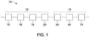
- FIG. 1 is a schematic diagram of an apparatus 10 for manufacturing membranes 50. While the apparatus 10 is suitable for the manufacture of various types of membranes 50, it is preferably used in the manufacture of ion exchange membranes.
- the apparatus comprises two primary sections: a casting section 12 and a processing section 14.
- the casting section 12 comprises a roll section 15, a film sealing section 16, a nip section 18 and a curing section 20.
- the casting section 12 is similar to the system described in U.S. Patent No. 5,264,125 .
- the processing section 14 comprises one or more of a conditioning section 54, a leak test section 64, a cutting section 74 and a conveyor system 51, which is shown in in Figure 1A .
- the roll section 15 includes a substrate feeder 22 that feeds a sheet of substrate 24 into the remainder of the apparatus 10.
- the substrate 24 is alternatively called a base material or a support layer and various suitable examples are commercially available.
- a substrate 24 is typically made up of one or more polymers, for example acrylic, polypropylene or polyester that can be extruded into yarns and woven into a fabric or combined into a non-woven fabric.
- the substrate 24 can be provided on rolls in the substrate feeder 22.
- the roll section 15 also includes two film feeders 26 that each feed a sheet of film 28 into parts of the remainder of the apparatus 10.
- the films 28 can be prepared from any type of material that is generally impermeable to volatile components and to a curable liquid and allows the membranes 50 to be separated from the films 28.
- the films 28 may be made of thermoplastic polymer resins of the polyester family such as polyethylene terephthalate.
- the films 28 may be between 0,005 to 0,025 cm (0.002 inches to 0.010 inches) thick, or other sizes.
- the films 28 can be provided on rolls in the film feeders 26.
- the substrate feeder 22 and the film feeders 26 may be passive or the feeders 22, 26 may apply a resistance to unrolling.
- feeders 22, 26 are powered by one or more motors 11 to encourage unrolling and to provide a desired line speed and tension of the membrane 50 as it is conveyed through the apparatus 10.
- other features that are described below contribute to maintaining the desired line speed and tension.
- the film feeders 26 can provide a quantity of the same film 28.
- each film feeder 26 may provide a different film 28.
- the substrate feeder 22 and the film feeders 26 are arranged to feed the substrate 24 between the two films 28.
- the resulting arrangement of the substrate 24 and the films 28 travels through the apparatus 10 with a respective longitudinal centerline of the substrate 24 and the films 28 moving essentially in a single plane.
- the substrate 24 and the films 28 may be brought into a desired spacing or alignment relative to each other by passing over one or more devices, such as rollers, belt, guides or other suitable devices (not shown).
- the film sealing section 16 includes an edge sealing device (not shown) that seals the edges of the films 28 together. Preferably the films 28 are sealed beyond the edges of the substrate 24 that is located between the films 28.
- the edge sealing device provides an energy source, for example a heater or ultrasonic welder, to melt the edges of the films 28.
- the edge sealing device can also include a presser (not shown) for pressing the melted edges together. The pressing step may be performed after or during the step of melting the edges. Sealing the edges of the films 28 together forms a pocket film 28 with the substrate 24 located between the films 28.
- the pocket of film 28 may also be referred to as a substrate and film sandwich. The film pocket facilitates the substrate wetting process that occurs in the nip section 18, to be described below. However, in a modified or other wetting process, the film sealing section 16 may be omitted.
- the nip section 18 includes a liquid feeder 34 that provides a curable liquid 36 into the film pocket and between the films 28 to wet the substrate 24.
- the wetted substrate 24 is also referred to as a membrane precursor 32.
- the liquid feeder 34 includes a reservoir (not shown) that contains the curable liquid 36 and one or more feeding tubes 38 that feed the curable liquid 36 from the reservoir to wet the substrate 24.
- the feeding tubes 38 extend from the liquid feeder 34, past the edge sealing device, and terminate above a pair of nip rollers 40.
- Figure 1A depicts the liquid feeder 34 as shown above the roll section 15, various other orientations are possible.
- the curable liquid 36 can collect in a pool above the pair of nip rollers 40.
- the space between the nip rollers 40 is set to produce a membrane precursor 32 of a desired thickness.
- the feeding tubes 38 can temporarily provide an amount of the curable liquid 36 that exceeds the amount of curable liquid 36 that travels with the substrate 24 past the nip rollers 40.
- the excess curable liquid 36 pools above the nip rollers 40.
- any curable liquid used to cast a supported membrane between two films may be used.
- the curable liquid 36 can be as described in U.S. 5,264,125 .
- the curable liquid 36, the substrate 24 and the films 28 are selected to be compatible with each other.
- other chemicals such as diluents and polymerization initiators may be part of the curable liquid 36 or added to the curable liquid 36 within the liquid feeder 34 or added into the pool of curable liquid 36 above the nip rollers 40.
- the diluents and polymerization initiators may be as described in U.S. 5,264,125 .
- the height of the pool of excess curable liquid 36 above the nip rollers 40 can be controlled to adequately wet the substrate 24 to form the membrane precursor 32.
- the height of the curable liquid 36 above the nip rollers 40 can be monitored by a sensor 84 that provides pool height information to a controller 82.
- the controller 82 preferably includes one or more programmable devices such as a processor or microprocessor, computer, Field Programmable Gate Array, or programmable logic controller (PLC).
- PLC programmable logic controller
- the controller 82 may comprise one or more non-programmable control elements, such as a timer or pneumatic or electric circuit, capable of implementing a sequence of operations.
- the controller 82 compares the pool height information to a pre-set height value or range and determines any difference between the height information and the pre-set height value or range to generate a pool height error signal. Based upon the pool height error signal, the controller 82 can command the liquid feeder 34 to provide more or less curable liquid 36.
- the pre-set height value or range can be between about 2 and about 15 cm.
- the pre-set height value or range can be selected to provide sufficient contact time between the substrate 24 and the curable liquid 36 to create the membrane precursor 32.
- the liquid feeder 34 further includes a pumping system that delivers curable liquid 36 based upon commands received from a controller 82.
- the membrane precursor 32 and the films 28 pass through the nip rollers 40 and then move to the curing section 20.
- the membrane precursor 32 and the films 28 can be supported on a continuous or segmented platform 42, which conveys the membrane precursor 32 and the films 28 through the curing section 20.
- the platform 42 is moved by a motor 11a.
- One or more curing devices 44 produce conditions in the curing section 20 that support a polymerization reaction by which the curable liquid 36 forms a solid polymer.
- the polymerization reaction transforms the membrane precursor 32 into the membrane 50.
- the curable liquid 36 may be cured by heat or by infrared, microwave, ultraviolet or other forms of radiation.
- the membrane precursor 32 may be heated to a temperature of from about 40°C to about 200°C to initiate and maintain the polymerization reaction.
- the curing section 20 may be in the range of about 2 to about 20 meters long.
- the residence time in the curing section 20 may be in the range of about 4 to about 40 minutes. These temperatures and times may vary depending on the curable liquid 36 used and the polymerization reaction.
- the processing section 14 Upon leaving the curing section 20, the membrane 50 and the films 28 are conveyed through the processing section 14.
- the processing section 14 comprises one or more sections, such as a conditioning section 54, a leak test section 64 and, a cutting section 74, and the conveyor system 51.
- the conveyor system 51 includes a series of rollers 53 that convey the membrane through the sections of the processing section 14.
- the processing section 14 includes a second pair of nip rollers 46 that receives the membrane 50 and the films 28 following the curing section 20.
- a knife 48 is located before, or after, the second pair of nip rollers 46 for trimming the edges of the films 28.
- the processing section 14 also includes film rollers 52 that separate the films 28 from the membrane 50. The film rollers 52 peel the films 28 from the membrane 50 and roll them up.
- One or more of the film rollers 52 can be driven by one or more motors 11b to facilitate moving the membrane precursor 32, the membrane 50 and the films 28 through the casting section 12.
- the processing section 14 includes a conditioning section 54 that treats the membrane 50 to reduce an amount of residues in the membrane 50.
- the residues are components of the membrane precursor 32 that do not participate, either partially or fully, in the polymerization reaction.
- the residues may also be referred to as polymerization reaction residues.
- the residues can be distributed evenly, or unevenly, throughout the membrane 50.
- the residues may comprise monomers, oligomers, polymers, solvents, unreacted reactants, polymerization initiators, catalysts or a combination thereof.
- the residues may also comprise various ions, chemicals or combinations thereof.
- the residues may include various ion species such as sulfonate ions, chloride ions, iodide ions, bromide ions, lithium ions, lithium hydroxide ions, sodium ions, hydrogen ions or a combination thereof.
- ion species such as sulfonate ions, chloride ions, iodide ions, bromide ions, lithium ions, lithium hydroxide ions, sodium ions, hydrogen ions or a combination thereof.
- the residues may also include various chemicals, including dipropyleneglycol (DPG), propyleneglycol, glycol derivatives, alcohols such as n-propanol, iso-propanol, n-butanol, iso-butanol, alcohol derivatives, ethers and ether derivatives, esters and ester derivatives, N-methyl pyrrolidone (NMP), amines and amine derivatives, amides and amide derivatives, sulfonic group derivatives, tertiary ammonium group derivatives or a combination thereof.
- DPG dipropyleneglycol
- propyleneglycol glycol derivatives
- alcohols such as n-propanol, iso-propanol, n-butanol, iso-butanol
- alcohol derivatives such as n-propanol, iso-propanol, n-butanol, iso-butanol
- alcohol derivatives such as n
- the conditioning section 54 includes one or more conditioning tanks. Conditioning tanks can also be referred to as extraction tanks or washing tanks. Each conditioning tank can be filled with water, or an aqueous solution or a solvent or some other liquid. When a conditioning tank is filled with water, the water is preferably substantially de-ionized, for example with a conductivity of 50 microS/cm or less. However, water with higher conductivity may still be considered to compose a water tank. A non-water tank may also contain mostly water, but the water is mixed with another compound to modify its reaction with the membrane.
- the conditioning section 54 may consist of only one non-water tank, more than one non-water tank, one or more non-water tanks positioned before or after a water tank, only one water tank, more than one water tank, one or more water tanks positioned before or after a non-water tank or other combinations of one or more conditioning tanks.
- a conditioning tank containing water preferably with a conductivity of 50 microS/cm or less, is used alone or as the first tank in a series of conditioning tanks.
- the conditioning section 54 includes two conditioning tanks, an extraction tank 56 and a washing tank 58.
- the extraction tank 56 can hold extraction fluids. Extraction fluids decrease the amount of residues within the membrane 50 as it is conveyed through the extraction tank 56 by the conveyor system 51.
- the extraction fluids may comprise organic ionic solutions, inorganic ionic solutions, organic non-ionic solutions, inorganic non-ionic solutions, substantially pure organic solvents, substantially pure inorganic solvents, organic solutions with additives, inorganic solutions with additives or a combination thereof.
- the extraction tank 56 may contain a sodium chloride solution, a bicarbonate solution, a citric acid solution, a lactic acid solution, an acetic acid solution, a hydroxide solution, a solution containing one or more surfactants or a combination thereof.
- the pH of the extraction solutions can vary with its intended purpose. For example, if it is desired to reduce any basic residues, the pH of the extraction solutions can be maintained in a range of about 2 to 4. This acidic pH range can be achieved and maintained by the addition of citric acid, acetic acid or other suitable acid solutions. If it desired to reduce any acidic residues, the pH of the extraction solutions can be maintained in a range of 9 to 13, for example, by the addition of bicarbonate.
- the extraction tank 56 can be of a variety of shapes and dimensions.
- the conveyor system 51 conveys the membrane 50 through the extraction tank 56 either partially or fully submerged in the extraction fluids.
- the conveyor system 51 can convey the membrane 50 through the extraction tank 56 vertically, horizontally, on an inclined path or on a declined path, or a combination thereof. Further, the conveyor system 51 can make one or more passes through the extraction tank 56.
- the wash tank 58 preferably downstream from the extraction tank 56.
- the wash tank 58 contains water to wash the extraction fluids and at least some of the residues from the membrane 50.
- the water may replace any extracted residues within the membrane 50 and wet the membrane 50.
- Various types of water are suitable, including filtered water, distilled water, double distilled water, de-ionized water with conductivity of less than about 50 microS/cm, reverse osmosis permeate water and the like.
- the water may be recycled through one or more steps of washing and water with a higher conductivity may be used.
- the water can be maintained at a pH range of about 5 to 8 with a preferred pH of about 7.
- the pH of the water can be maintained at a higher or lower pH depending upon the pH of the extraction fluids in the extraction tank 56.
- the conveyor system 51 conveys the membrane 50 from the conditioning section 54 to the leak test section 64.
- the leak test section 64 includes a dye applicator 66 and a contrast feeder 68.
- the dye applicator 66 can automatically apply a dye to an upper surface of the membrane 50.
- the dye applicator 66 can include a dye reservoir 67, a pumping system 69 and a distribution pipe 71.
- the distribution pipe 71 has one or more nozzles.
- the pumping system 69 draws dye from the dye reservoir 67 and distributes dye through the one or more nozzles onto the upper surface of the membrane 50 as it is conveyed past the distribution pipe 71.
- the a leak test controller 83 can control the pumping system 69 to control the amount of dye distributed through the nozzles based upon on the speed at which the membrane 50 is conveyed past the distribution pipe 71.
- one or more spreaders may be provided downstream of the distribution pipe 71 to spread the dye evenly across the upper surface of the membrane 50.
- the spreaders may be brushes, rubber or metal blades, sponges, or the like.
- the leak test section includes a station 66a for housing an operator that can manually apply and evenly spread dye on the surface of the membrane 50.
- the dye can be a permanganate based dye, such as dark violet dye; a methylene blue based dye; a chromate based dye, such as a red/orange dye; Erythrosin B dye or another other suitable dye that is compatible with the membrane 50.
- the dye can be made into a solution in a range of about 1% to about 30% weight of the dye to a volume of water (wt/v). Preferably, the dye is made into a solution of about 5% wt/v.
- the dye When the dye is applied to the membrane 50, the dye can enter the upper surface of the membrane 50, pass through any physical flaws in the body of the membrane 50 and exit through a lower surface of the membrane 50.
- the physical flaws in the membrane 50 can be spaces, gaps, holes or the like within the membrane 50 that are caused by imperfect polymerization reaction conditions, the presence of contaminants within the curable liquid 36 or various other reasons.
- the physical flaws in the membrane 50 can be localized phenomena or widespread throughout the membrane 50.
- the contrast feeder 68 feeds a sheet of contrast material 70 into the remainder of the apparatus 10.
- the contrast feeder 68 can be positioned before, within or after the dye applicator 66.
- the contrast material 70 is provided on rolls in the contrast feeder 68.
- the contrast feeder 68 feeds the contrast material 70 from below the membrane 50 upwards between the rollers 53 of the conveyor system 51.
- the sheet of contrast material 70 contacts the lower surface of the membrane 50. Any dye that passes through physical flaws in the membrane 50 will exit the membrane 50 and mark the contrast material 70 at or close to where the dye exited the membrane 50.
- the contrast material 70 can be made of one of various materials that provide a high visual contrast with the dye.
- the dye can mark the contrast material 70 in a manner that will not be significantly reduced or removed by the remainder of the processing section 14.
- the contrast material 70 can be cloth, paper cloth, cellulose-fiber based cloth, or polypropylene and the dye may clearly mark the contrast material 70 and provide a visual indication of any portions of the membrane 50 that contain physical flaws.
- the conveyor system 51 conveys the membrane 50 and the contrast material 70 from the leak test section 64 to the cutting section 74.
- the cutting section 74 has one or more blades to cut the membrane 50, and optionally the contrast material 70, into various desired sizes for storage and transport.
- the cutting section 74 includes an inspection station 76 positioned either before or after the membrane 50 is cut. Within the inspection station 76, an operator can identify any dye marked portions of the contrast material 70 that indicate regions of the membrane 50 with physical flaws.
- the cutting section 74 can be automated based upon a count algorithm and the line speed of the conveyor system 51 to produce a final membrane 50 of a desired size.
- the cutting section 74 can be manually operated.
- the conveyor system 51 conveys the membrane 50 through the processing section 14 by the rollers 53. While the examples of Figures 1A and 1B depict the conveyor system 51 as having multiple turns, this is provided for ease of depiction. For example, the conveyor system 51 could include one or more or no turns.
- the conveyor system 51 can be configured to meet the physical footprint requirements of the location where the apparatus 10 is installed and operating. Preferably, the conveyor system 51 conveys the membrane 50 as a continuous structure that extends along a path of travel from the curing section 20 through to the cutting section 74. However, other configurations are possible.
- the rollers 53 are located at various points throughout the processing section 14 and support the membrane 50.
- the rollers 53 define the path of travel through the processing section 14.
- the membrane 50 is conveyed in a central position, with respect to a width of the rollers 53, along the path of travel.
- One or more devices, such as rollers, belts or guides (not shown) can maintain membrane 50 in the central position along the path of travel.
- rollers 53a can be actively rotated by a motor 81.
- none of the rollers 53 are actively rotated by the motor 81 and the movement of the membrane 50 through the processing section 14 is dependent upon other features of the apparatus 10.
- at least some of the rollers 53a are actively rotated by the motor 81.
- Actively driven rollers 53a convey the membrane 50 at the desired line speed and the desired tension through the processing section 14.
- the rollers 53 that are not actively rotated by the motor 81 may be passively rotated by the membrane 50 moving along the path of travel.
- the motor 81 can be a series of motors that individually drive each roller 53a.
- the rollers 53a can be connected by a belt drive (not shown) that is driven by one or more motors 81.
- rollers 53, 53a can be organized into localized sections with the rollers 53a of each localized section connected by a belt drive that is driven by one or more motors 81.
- one localized roller section can convey the membrane 50 from the end of the curing section 20 through the conditioning section 54.
- a second localized roller section can convey the membrane 50 from the conditioning section 54 through the leak text device 64 and a third localized roller section can convey the membrane 50 through the remainder of the processing section 14.
- the conveyor system 51 can include any number of localized roller sections.
- the motor 81 can be a servo motor, stepper motor or any other motor that can be pre-programmed or that will respond to commands from a conveyor or controller 82.
- the multiple motors 81 can rotate all of the rollers 53a, or all of the drive belts that rotate the rollers 53a, at the same desired rate.
- the rate of rotation determines the line speed of the membrane 50 along the path of travel and through the processing section 14.
- the rollers 53a rotate at the same rate to provide a consistent line speed.
- the line speed regulates the residence time of the membrane 50 through the conditioning section 54 and the line speed can dictate the overall production rate of the apparatus 10. Maintaining a consistent line speed also regulates the tension of the membrane 50 throughout the processing section 14.
- the tension of the membrane 50 keeps the membrane 50 flat to prevent pooling of the extraction fluids and water on the upper surface of the membrane 50, which can interfere with evenly applying the dye during the leak testing.
- different tensions may be used through the processing section 14 and other sections of the apparatus 10.
- the motor 81 includes a tachometer that provides rotary velocity information to the controller 82.
- the controller 82 compares the rotary velocity information with a pre-set rotary velocity value and generates an error signal.
- the pre-set rotary velocity corresponds with the desired line speed.
- the error signal is the difference between the actual rotary velocity and the pre-set rotary velocity value.
- the controller 82 mathematically transforms the error signal into a velocity adjustment signal, which is sent to the motor 81.
- the motor 81 adjusts its rotary velocity.
- the tachometer can be one of various rotary velocity sensors or angular position sensors, for example digital sensors, contact-based sensors, magnetic-based sensors and the like.
- roller velocity sensors provide roller velocity information to the controller 82.
- the controller 82 compares the roller velocity information with a pre-set roller velocity value and generates a roller velocity error signal.
- the pre-set roller velocity may also correspond with the desired line speed.
- the error signal is the difference between the actual roller velocity and the pre-set roller velocity value.
- the roller velocity error signal is mathematically transformed and added to the velocity adjustment signal, which is sent to the motor 81 and the motor 81 adjusts its rotary velocity.
- the roller velocity sensors can be one of various rotary velocity sensors and angular position sensors, for example digital sensors, contact-based sensors, magnetic-based sensors or the like.
- the apparatus 10 allows for a continuous production and processing of a membrane 50.
- the membrane 50 can be continuous with the membrane precursor 32, which is continuous with the substrate 24 as it is fed into the apparatus 10.
- the substrate 24 can be of sufficient tensile strength so that as the conveyor system 51 conveys the membrane 50 through the processing section 14, the upstream portions of the substrate 24, including the membrane precursor 32, can be pulled through the casting section 12 at the desired line speed.
- the motors 11, 11a and 11b can be similar to the motor 81.
- the motors 11, 11a and 11b can be programmed to run at a rotational velocity that matches the desired line speed of the conveyor system 51.
- the controller 82 can regulate the rotational velocity of the motors 11, 11a and 11b to match the desired line speed of the conveyor system 51.
- the speed at which the roll section 15 forms the film pocket, the speed at which the film sealing section 16 seals the film pocket, the speed at which the nip section 18 wets the substrate 24 to form the membrane precursor 32 and the speed at which the curing section 20 cures the membrane precursor 32 into a membrane 50 can all be substantially the same speed.
- the speed at which the casting section 12 casts the membrane 50 can be substantially the same speed as the speed the conveyor system 51 conveys the membrane 50 through the processing section 14.
- the conveyor system 51 can further comprise a platform 60 that rests on the rollers 53, 53a and supports the membrane 50 throughout the processing section 14.
- the platform 60 can be segmented or continuous.
- the rollers 53a move the membrane 50 across the platform 60 at the desired line speed.
- the platform 60 has a first section 60a and a second section 60b.
- the first and second sections 60a, 60b are separated by a gap 60c that allows the contrast material 70 to be fed between the lower surface of the membrane 50 and the upper surface of the platform 60.
- the platform 60 can be continuous with the platform 42 of the curing section 20.
- the apparatus 10 can be modular and permits various configurations of the processing section 14.
- the processing section 14 can include one or more further extraction tanks 56a.
- the further extraction tanks 56a may be the same as the extraction tanks 56, or not. If the membrane 50 is made with a curable liquid 36 that produces a greater amount of residues, the further extraction tanks 56a can be provided to remove more residues.
- the further extraction tanks 56a can be positioned before or after the leak test section64 and before the cutting section 74.
- the further extraction tanks 56a may be accompanied by further wash tanks 58a, or not.
- the further wash tanks 58a may be the same as the wash tanks 58, or not.
- the water can be cyclically recycled between wash tanks 58, 58a, for example in a cascade flow system.
- the extraction fluids can be the same or different between the extraction tanks 56, 56a. If the extraction fluids are the same, the concentration of the extraction fluids can be the same or different between the extraction tanks 56, 56a.
- the water can be the same or not between the water tanks 58, 58a.
- the processing section 14 can further include a dye removal device 72 that removes any excess dye from the upper surface of the membrane 50.
- the dye removal device 72 comprises one or more brushes, rubber or metal blades, sponges, wipers, a blower and combinations thereof that are positioned above or beside the path of travel.
- a blower 63 is positioned at the downstream end of the conditioning section 54.
- the blower 63 provides a pressurized stream of air, or other suitable inert gas, to remove any residual extraction fluids and water from the upper surface of the membrane 50.
- the extraction tank 56 and the wash tank 58 each comprise a pump and circulation loop (not shown).
- the pump and circulation loop agitates the fluids within the respective tanks.
- the pump and circulation loop also withdraws and replenishes the fluids to optimize their respective conditions, such as pH, and to remove any particulate matter and other contaminants or waste from the tanks 56, 58.
- the extraction tank 56 and the wash tank 58 include a cover.
- the cover prevents the loss of any sprayed fluids, gaseous fluids and volatiles from the tanks 56, 58.
- the cover also provides thermal insulation so that a temperature regulation system (not shown) can maintain a temperature of the fluids within a range of about 0oC to about 85oC.
- a temperature regulation system (not shown) can maintain a temperature of the fluids within a range of about 0oC to about 85oC.
- the temperature in the tanks 56, 58 is maintained in a range of about 5 oC to 70 oC.
- a motor 73 actively drives the contrast feeder 68 to feed the contrast material 70.
- the motor 73 can receive commands from the controller 82 to match the rate at which the contrast material 70 is introduced into the leak test section64 with the desired line speed of the membrane 50.
- the rollers 53, 53a are positioned within the extraction tank 56 and the membrane 50 makes more than one pass through the extraction fluids.
- the rollers 53, 53a convey the membrane 50 through a series of switchbacks through the extraction tank 56.
- the multiple passes increase the length of the path of travel within the extraction tank 56, which increases the overall residence time within the extraction tank 56 without necessitating a larger sized extraction tank 56.
- one or more storage rollers can be provided.
- a storage roller may be positioned prior to the curing section 20 for collecting and storing the membrane precursor 32 and the films 28 by rolling them up.
- another storage roller can collect and store the membrane 50, with or without the films 28, after the curing section 20.
- the storage rollers allow portions of the membrane precursor 32 and the membrane 50, as the case may be, to be moved from one location to another.
- storage rollers can be used in a facility that does not have an adequate physical foot print to position all of the features of the apparatus 10 in close proximity to each other.
- the collected and stored membrane precursor 32 and membrane 50 can be introduced from the storage rollers onto a roller 53, 53a, or alternatively onto the platform 60, and then conveyed through the processing section 14.
- edge guide sensors are positioned on both sides of the conveyor system 51 at various points along the path of travel.
- the edge guide sensors can detect if the membrane 50 shifts from the central position. When such a shift is detected, the edge guide sensors generate a misalignment signal that is sent to the controller 82.
- the controller 82 Upon receiving the misalignment signal, the controller 82 generates an alignment signal that is sent to one or more alignment members that are positioned along the path of travel.
- the alignment members can adjust the position of the membrane 50 back to the central position.
- the edge guide sensors stop generating the misalignment signal and the controller 82 stops generating the alignment signal.
- the edge guide sensors can be optical sensors, touch sensors or the like.
- the alignment members can include guides, gates or adjustable rollers that can laterally alter the course of the membrane 50 as it is conveyed along the path of travel.
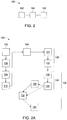
- FIG. 2 is a schematic flow chart of a method 100 for manufacturing membranes 50.
- the method 100 comprises the steps of casting a precursor 102, curing the precursor to form a cured membrane 104 and processing the cured membrane 106.
- the cured membrane is preferably conveyed through at least the processing step 106.
- the step of casting a precursor 102 comprises a step of forming a film pocket 108, a step of sealing the pocket 109 and wetting 110 the substrate 24 within the film pocket.
- the pocket is formed 108 by layering the substrate 24 between two layers of film 28.
- the step of sealing the pocket 109 includes melting at least a portion of the lateral edges of the film pocket and pressing the melted portions together to form a seal.
- the melting step may be achieved by various approaches, including heat, pressure, ultrasonic welding, chemical welding and combinations thereof.
- the curable liquid 36 is introduced into the pocket to wet 110 the substrate 24 and form the membrane precursor 32.
- the step of curing the precursor to form a cured membrane 104 comprises a step of either heating or irradiating the membrane precursor 32, or both.
- the membrane precursor 32 can be irradiated with infrared, microwave, ultraviolet or other forms of radiation.
- the curable liquid 34 under goes a polymerizing reaction and the membrane precursor 32 changes into a cured form of the membrane 50.
- the processing step 106 comprises the steps of separating the films 28 from the membrane 50 and conditioning 120 the membrane 50.
- the separated films 28 can be recycled or reused.
- Conditioning 120 the membrane 50 includes a step of extracting residues 121 from the membrane 50 by soaking or flushing the membrane 50 with extraction fluids.
- the step of extracting residues 121 can also include a step of optimizing the conditions to increase the amount of residues that are extracted. For example, temperature, pH and the chemical composition of the extraction fluids can be optimized based upon the type of residues that are within the membrane 50.
- the conditioning step 120 can also include a step of washing 122 the extraction fluids from the membrane 50.
- the steps of extracting 121 and washing 122 can be repeated, or prolonged, by conveying the membrane 50 multiple times through one extraction tank 56 and one wash tank 58.
- the membrane 50 can be conveyed through one or more extraction tanks 56 and one or more wash tanks 58.
- the processing step 106 further includes a step of testing 124 the membrane 50.
- the testing step 124 includes a step of applying 126 a dye to a surface of the membrane 50 and providing 128 a contrast material 70 to a surface of the membrane 50 that is opposite to the dyed surface. Dye that flows through any physical flaws in the membrane 50 will mark the contrast material 70.
- the dye marked contrast material 70 provides a visual cue that the membrane 50 contains physical flaws.
- the testing step 124 can also include a step of removing excess dye from the dyed surface of the membrane 50.
- the testing step 124 further includes a step of inspecting 130 the contrast material 70 for dye marks. For example, an operator can inspect the contrast material 70 to identify flawed regions of the membrane 50 as regions where there are dye marks on the contrast material 70.
- the processing step 106 further includes a step of cutting 132 the membrane 50 to a desired size.
- the step of inspecting 130 can occur after the cutting 132 step (as indicated by the stippled arrows in Figure 2A ).
- the membrane 50 is conveyed between process step areas at a desired speed and a desired tension along a path of travel, for example upon the rollers 53, 53a or the platform 60.
- the processing steps 106 adapted to be performed at a common line speed.
- the line speed can be pre-set based upon the components of the curable liquid 36, or other factors, and stored in the controller 82.
- various pre-set line speeds may be stored in the controller 82 for various different curable liquids 36 to optimize the time for the steps of extracting residues 121 and washing 122 the membrane 50.
- the user may input the type of curable liquid 36 into the controller 82.
- the controller 82 selects the pre-set line speed and regulates the line speed of the conveyor system 51 to match the pre-set line speed.
- the membrane 50 can be continuously conveyed at the desired line speed from the curing step 104 through all the processing steps 106.
- the membrane 50 is continuous with the membrane precursor 32, which is continuous with the substrate 24, and the substrate 24, the membrane precursor 32 and the membrane 50 are continuously conveyed through all steps of the method 100.
Landscapes
- Chemical & Material Sciences (AREA)
- Engineering & Computer Science (AREA)
- Chemical Kinetics & Catalysis (AREA)
- Manufacturing & Machinery (AREA)
- Health & Medical Sciences (AREA)
- Biochemistry (AREA)
- Medicinal Chemistry (AREA)
- General Health & Medical Sciences (AREA)
- General Physics & Mathematics (AREA)
- Immunology (AREA)
- Pathology (AREA)
- Inorganic Chemistry (AREA)
- Life Sciences & Earth Sciences (AREA)
- Physics & Mathematics (AREA)
- Materials Engineering (AREA)
- Dispersion Chemistry (AREA)
- Analytical Chemistry (AREA)
- Polymers & Plastics (AREA)
- Organic Chemistry (AREA)
- Mechanical Engineering (AREA)
- Separation Using Semi-Permeable Membranes (AREA)
- Moulding By Coating Moulds (AREA)
- Casting Or Compression Moulding Of Plastics Or The Like (AREA)
- Addition Polymer Or Copolymer, Post-Treatments, Or Chemical Modifications (AREA)
- Laminated Bodies (AREA)
- Application Of Or Painting With Fluid Materials (AREA)
Description
-
US Patent Number 5,264,125 , entitled Process for Manufacturing Continuous Supported Ion Selective Membranes Using Non-Polymerizable High Boiling Point Solvents, describes a process for making a supported ion exchange membrane. The process comprises forming a sandwich of a substrate and a pliable film on each face of the substrate. The films extend beyond the side edges of the substrate. The edges of the films are sealed together to form a pocket containing the substrate. Subsequently, the sandwich is pulled between a pair of squeeze rolls. A liquid is added to the pocket above the squeeze rolls to form a pool of the liquid above the squeeze rolls and between the films. The liquid wets the substrate and fills apertures in the substrate before the sandwich passes through the squeeze rolls. From the squeeze rolls, the sandwich passes through a set of means, for example heaters, for curing the liquid. Polymerizable components in the liquid are polymerized thereby forming a reinforced polymer sheet. The sandwich proceeds through a set of knives which remove the seals at the edges of the sandwich and through a pair of rollers which remove the films from the polymer sheet. The polymer sheet is then an ion exchange membrane. -
US 2009/110998 describes a solid electrolyte membrane, a membrane electrode assembly and a fuel cell, along with a method and apparatus for producing the solid electrolyte membrane. - The invention is defined by the claims, to which reference should now be made. Examples of the invention are described in more detail below.
-
-
Figure 1 is a schematic diagram of an apparatus for manufacturing membranes. -
Figure 1A is a diagram of an example of an apparatus according toFigure 1 . -
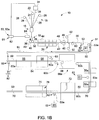
Figure 1B is a diagram of another example of an apparatus according toFigure 1 . -
Figure 2 is a schematic flow chart of a process for manufacturing membranes. -
Figure 2A is a flow chart of an example of a process according toFigure 2 . -
Figure 1 is a schematic diagram of anapparatus 10 formanufacturing membranes 50. While theapparatus 10 is suitable for the manufacture of various types ofmembranes 50, it is preferably used in the manufacture of ion exchange membranes. The apparatus comprises two primary sections: acasting section 12 and aprocessing section 14. Thecasting section 12 comprises aroll section 15, afilm sealing section 16, anip section 18 and acuring section 20. Thecasting section 12 is similar to the system described inU.S. Patent No. 5,264,125 . - The
processing section 14 comprises one or more of aconditioning section 54, aleak test section 64, acutting section 74 and aconveyor system 51, which is shown in inFigure 1A . - In the example of
Figure 1A , theroll section 15 includes asubstrate feeder 22 that feeds a sheet ofsubstrate 24 into the remainder of theapparatus 10. Thesubstrate 24 is alternatively called a base material or a support layer and various suitable examples are commercially available. Asubstrate 24 is typically made up of one or more polymers, for example acrylic, polypropylene or polyester that can be extruded into yarns and woven into a fabric or combined into a non-woven fabric. Optionally, thesubstrate 24 can be provided on rolls in thesubstrate feeder 22. - The
roll section 15 also includes twofilm feeders 26 that each feed a sheet offilm 28 into parts of the remainder of theapparatus 10. Thefilms 28 can be prepared from any type of material that is generally impermeable to volatile components and to a curable liquid and allows themembranes 50 to be separated from thefilms 28. For example, thefilms 28 may be made of thermoplastic polymer resins of the polyester family such as polyethylene terephthalate. Thefilms 28 may be between 0,005 to 0,025 cm (0.002 inches to 0.010 inches) thick, or other sizes. Optionally, thefilms 28 can be provided on rolls in thefilm feeders 26. - The
substrate feeder 22 and thefilm feeders 26 may be passive or thefeeders feeders more motors 11 to encourage unrolling and to provide a desired line speed and tension of themembrane 50 as it is conveyed through theapparatus 10. Optionally, other features that are described below contribute to maintaining the desired line speed and tension. - The
film feeders 26 can provide a quantity of thesame film 28. Optionally, eachfilm feeder 26 may provide adifferent film 28. - The
substrate feeder 22 and thefilm feeders 26 are arranged to feed thesubstrate 24 between the twofilms 28. The resulting arrangement of thesubstrate 24 and thefilms 28 travels through theapparatus 10 with a respective longitudinal centerline of thesubstrate 24 and thefilms 28 moving essentially in a single plane. Thesubstrate 24 and thefilms 28 may be brought into a desired spacing or alignment relative to each other by passing over one or more devices, such as rollers, belt, guides or other suitable devices (not shown). - The
substrate 24 and thefilms 28 pass from theroll section 15 to thefilm sealing section 16. Thefilm sealing section 16 includes an edge sealing device (not shown) that seals the edges of thefilms 28 together. Preferably thefilms 28 are sealed beyond the edges of thesubstrate 24 that is located between thefilms 28. The edge sealing device provides an energy source, for example a heater or ultrasonic welder, to melt the edges of thefilms 28. The edge sealing device can also include a presser (not shown) for pressing the melted edges together. The pressing step may be performed after or during the step of melting the edges. Sealing the edges of thefilms 28 together forms apocket film 28 with thesubstrate 24 located between thefilms 28. The pocket offilm 28 may also be referred to as a substrate and film sandwich. The film pocket facilitates the substrate wetting process that occurs in thenip section 18, to be described below. However, in a modified or other wetting process, thefilm sealing section 16 may be omitted. - The
nip section 18 includes aliquid feeder 34 that provides acurable liquid 36 into the film pocket and between thefilms 28 to wet thesubstrate 24. The wettedsubstrate 24 is also referred to as amembrane precursor 32. Theliquid feeder 34 includes a reservoir (not shown) that contains thecurable liquid 36 and one ormore feeding tubes 38 that feed thecurable liquid 36 from the reservoir to wet thesubstrate 24. Thefeeding tubes 38 extend from theliquid feeder 34, past the edge sealing device, and terminate above a pair ofnip rollers 40. AlthoughFigure 1A depicts theliquid feeder 34 as shown above theroll section 15, various other orientations are possible. - The
curable liquid 36 can collect in a pool above the pair ofnip rollers 40. The space between thenip rollers 40 is set to produce amembrane precursor 32 of a desired thickness. Thefeeding tubes 38 can temporarily provide an amount of thecurable liquid 36 that exceeds the amount ofcurable liquid 36 that travels with thesubstrate 24 past thenip rollers 40. The excess curable liquid 36 pools above thenip rollers 40. - Any curable liquid used to cast a supported membrane between two films may be used. For example, the
curable liquid 36 can be as described inU.S. 5,264,125 . Thecurable liquid 36, thesubstrate 24 and thefilms 28 are selected to be compatible with each other. Optionally, other chemicals such as diluents and polymerization initiators may be part of thecurable liquid 36 or added to thecurable liquid 36 within theliquid feeder 34 or added into the pool ofcurable liquid 36 above thenip rollers 40. For example, the diluents and polymerization initiators may be as described inU.S. 5,264,125 . - In one option of the
apparatus 10, the height of the pool of excesscurable liquid 36 above the niprollers 40 can be controlled to adequately wet thesubstrate 24 to form themembrane precursor 32. For example, the height of thecurable liquid 36 above the niprollers 40 can be monitored by asensor 84 that provides pool height information to acontroller 82. Thecontroller 82 preferably includes one or more programmable devices such as a processor or microprocessor, computer, Field Programmable Gate Array, or programmable logic controller (PLC). Alternatively or additionally, thecontroller 82 may comprise one or more non-programmable control elements, such as a timer or pneumatic or electric circuit, capable of implementing a sequence of operations. - The
controller 82 compares the pool height information to a pre-set height value or range and determines any difference between the height information and the pre-set height value or range to generate a pool height error signal. Based upon the pool height error signal, thecontroller 82 can command theliquid feeder 34 to provide more or lesscurable liquid 36. For example, the pre-set height value or range can be between about 2 and about 15 cm. The pre-set height value or range can be selected to provide sufficient contact time between thesubstrate 24 and thecurable liquid 36 to create themembrane precursor 32. Optionally, theliquid feeder 34 further includes a pumping system that delivers curable liquid 36 based upon commands received from acontroller 82. - The
membrane precursor 32 and thefilms 28 pass through the niprollers 40 and then move to thecuring section 20. Themembrane precursor 32 and thefilms 28 can be supported on a continuous orsegmented platform 42, which conveys themembrane precursor 32 and thefilms 28 through thecuring section 20. Optionally, theplatform 42 is moved by amotor 11a. One ormore curing devices 44 produce conditions in thecuring section 20 that support a polymerization reaction by which the curable liquid 36 forms a solid polymer. The polymerization reaction transforms themembrane precursor 32 into themembrane 50. For example, thecurable liquid 36 may be cured by heat or by infrared, microwave, ultraviolet or other forms of radiation. In one embodiment, themembrane precursor 32 may be heated to a temperature of from about 40°C to about 200°C to initiate and maintain the polymerization reaction. The curingsection 20 may be in the range of about 2 to about 20 meters long. The residence time in thecuring section 20 may be in the range of about 4 to about 40 minutes. These temperatures and times may vary depending on thecurable liquid 36 used and the polymerization reaction. - Upon leaving the
curing section 20, themembrane 50 and thefilms 28 are conveyed through theprocessing section 14. Theprocessing section 14 comprises one or more sections, such as aconditioning section 54, aleak test section 64 and, acutting section 74, and theconveyor system 51. Theconveyor system 51 includes a series ofrollers 53 that convey the membrane through the sections of theprocessing section 14. - The
processing section 14 includes a second pair of niprollers 46 that receives themembrane 50 and thefilms 28 following thecuring section 20. Optionally, aknife 48 is located before, or after, the second pair of niprollers 46 for trimming the edges of thefilms 28. Theprocessing section 14 also includesfilm rollers 52 that separate thefilms 28 from themembrane 50. Thefilm rollers 52 peel thefilms 28 from themembrane 50 and roll them up. One or more of thefilm rollers 52 can be driven by one ormore motors 11b to facilitate moving themembrane precursor 32, themembrane 50 and thefilms 28 through thecasting section 12. - The
processing section 14 includes aconditioning section 54 that treats themembrane 50 to reduce an amount of residues in themembrane 50. The residues are components of themembrane precursor 32 that do not participate, either partially or fully, in the polymerization reaction. The residues may also be referred to as polymerization reaction residues. The residues can be distributed evenly, or unevenly, throughout themembrane 50. The residues may comprise monomers, oligomers, polymers, solvents, unreacted reactants, polymerization initiators, catalysts or a combination thereof. The residues may also comprise various ions, chemicals or combinations thereof. For example, the residues may include various ion species such as sulfonate ions, chloride ions, iodide ions, bromide ions, lithium ions, lithium hydroxide ions, sodium ions, hydrogen ions or a combination thereof. The residues may also include various chemicals, including dipropyleneglycol (DPG), propyleneglycol, glycol derivatives, alcohols such as n-propanol, iso-propanol, n-butanol, iso-butanol, alcohol derivatives, ethers and ether derivatives, esters and ester derivatives, N-methyl pyrrolidone (NMP), amines and amine derivatives, amides and amide derivatives, sulfonic group derivatives, tertiary ammonium group derivatives or a combination thereof. - The
conditioning section 54 includes one or more conditioning tanks. Conditioning tanks can also be referred to as extraction tanks or washing tanks. Each conditioning tank can be filled with water, or an aqueous solution or a solvent or some other liquid. When a conditioning tank is filled with water, the water is preferably substantially de-ionized, for example with a conductivity of 50 microS/cm or less. However, water with higher conductivity may still be considered to compose a water tank. A non-water tank may also contain mostly water, but the water is mixed with another compound to modify its reaction with the membrane. - The
conditioning section 54 may consist of only one non-water tank, more than one non-water tank, one or more non-water tanks positioned before or after a water tank, only one water tank, more than one water tank, one or more water tanks positioned before or after a non-water tank or other combinations of one or more conditioning tanks. In one example, a conditioning tank containing water, preferably with a conductivity of 50 microS/cm or less, is used alone or as the first tank in a series of conditioning tanks. In the example ofFigure 1A , theconditioning section 54 includes two conditioning tanks, anextraction tank 56 and awashing tank 58. Theextraction tank 56 can hold extraction fluids. Extraction fluids decrease the amount of residues within themembrane 50 as it is conveyed through theextraction tank 56 by theconveyor system 51. The extraction fluids may comprise organic ionic solutions, inorganic ionic solutions, organic non-ionic solutions, inorganic non-ionic solutions, substantially pure organic solvents, substantially pure inorganic solvents, organic solutions with additives, inorganic solutions with additives or a combination thereof. For example, theextraction tank 56 may contain a sodium chloride solution, a bicarbonate solution, a citric acid solution, a lactic acid solution, an acetic acid solution, a hydroxide solution, a solution containing one or more surfactants or a combination thereof. - The pH of the extraction solutions can vary with its intended purpose. For example, if it is desired to reduce any basic residues, the pH of the extraction solutions can be maintained in a range of about 2 to 4. This acidic pH range can be achieved and maintained by the addition of citric acid, acetic acid or other suitable acid solutions. If it desired to reduce any acidic residues, the pH of the extraction solutions can be maintained in a range of 9 to 13, for example, by the addition of bicarbonate.
- The
extraction tank 56 can be of a variety of shapes and dimensions. Theconveyor system 51 conveys themembrane 50 through theextraction tank 56 either partially or fully submerged in the extraction fluids. Theconveyor system 51 can convey themembrane 50 through theextraction tank 56 vertically, horizontally, on an inclined path or on a declined path, or a combination thereof. Further, theconveyor system 51 can make one or more passes through theextraction tank 56. - The
wash tank 58, preferably downstream from theextraction tank 56. Thewash tank 58 contains water to wash the extraction fluids and at least some of the residues from themembrane 50. The water may replace any extracted residues within themembrane 50 and wet themembrane 50. Various types of water are suitable, including filtered water, distilled water, double distilled water, de-ionized water with conductivity of less than about 50 microS/cm, reverse osmosis permeate water and the like. Optionally, the water may be recycled through one or more steps of washing and water with a higher conductivity may be used. The water can be maintained at a pH range of about 5 to 8 with a preferred pH of about 7. Optionally, the pH of the water can be maintained at a higher or lower pH depending upon the pH of the extraction fluids in theextraction tank 56. - The
conveyor system 51 conveys themembrane 50 from theconditioning section 54 to theleak test section 64. Theleak test section 64 includes adye applicator 66 and acontrast feeder 68. Thedye applicator 66 can automatically apply a dye to an upper surface of themembrane 50. Thedye applicator 66 can include adye reservoir 67, apumping system 69 and adistribution pipe 71. Thedistribution pipe 71 has one or more nozzles. Thepumping system 69 draws dye from thedye reservoir 67 and distributes dye through the one or more nozzles onto the upper surface of themembrane 50 as it is conveyed past thedistribution pipe 71. Optionally, the aleak test controller 83 can control thepumping system 69 to control the amount of dye distributed through the nozzles based upon on the speed at which themembrane 50 is conveyed past thedistribution pipe 71. Optionally, one or more spreaders (not shown) may be provided downstream of thedistribution pipe 71 to spread the dye evenly across the upper surface of themembrane 50. For example, the spreaders may be brushes, rubber or metal blades, sponges, or the like. As shown in the example ofFigure 1B , the leak test section includes astation 66a for housing an operator that can manually apply and evenly spread dye on the surface of themembrane 50. - The dye can be a permanganate based dye, such as dark violet dye; a methylene blue based dye; a chromate based dye, such as a red/orange dye; Erythrosin B dye or another other suitable dye that is compatible with the
membrane 50. The dye can be made into a solution in a range of about 1% to about 30% weight of the dye to a volume of water (wt/v). Preferably, the dye is made into a solution of about 5% wt/v. - When the dye is applied to the
membrane 50, the dye can enter the upper surface of themembrane 50, pass through any physical flaws in the body of themembrane 50 and exit through a lower surface of themembrane 50. The physical flaws in themembrane 50 can be spaces, gaps, holes or the like within themembrane 50 that are caused by imperfect polymerization reaction conditions, the presence of contaminants within thecurable liquid 36 or various other reasons. The physical flaws in themembrane 50 can be localized phenomena or widespread throughout themembrane 50. - The
contrast feeder 68 feeds a sheet ofcontrast material 70 into the remainder of theapparatus 10. Thecontrast feeder 68 can be positioned before, within or after thedye applicator 66. For example, thecontrast material 70 is provided on rolls in thecontrast feeder 68. In particular, thecontrast feeder 68 feeds thecontrast material 70 from below themembrane 50 upwards between therollers 53 of theconveyor system 51. The sheet ofcontrast material 70 contacts the lower surface of themembrane 50. Any dye that passes through physical flaws in themembrane 50 will exit themembrane 50 and mark thecontrast material 70 at or close to where the dye exited themembrane 50. Thecontrast material 70 can be made of one of various materials that provide a high visual contrast with the dye. The dye can mark thecontrast material 70 in a manner that will not be significantly reduced or removed by the remainder of theprocessing section 14. For example, thecontrast material 70 can be cloth, paper cloth, cellulose-fiber based cloth, or polypropylene and the dye may clearly mark thecontrast material 70 and provide a visual indication of any portions of themembrane 50 that contain physical flaws. - The
conveyor system 51 conveys themembrane 50 and thecontrast material 70 from theleak test section 64 to thecutting section 74. The cuttingsection 74 has one or more blades to cut themembrane 50, and optionally thecontrast material 70, into various desired sizes for storage and transport. The cuttingsection 74 includes aninspection station 76 positioned either before or after themembrane 50 is cut. Within theinspection station 76, an operator can identify any dye marked portions of thecontrast material 70 that indicate regions of themembrane 50 with physical flaws. Optionally, the cuttingsection 74 can be automated based upon a count algorithm and the line speed of theconveyor system 51 to produce afinal membrane 50 of a desired size. Alternatively, the cuttingsection 74 can be manually operated. - The
conveyor system 51 conveys themembrane 50 through theprocessing section 14 by therollers 53. While the examples ofFigures 1A and1B depict theconveyor system 51 as having multiple turns, this is provided for ease of depiction. For example, theconveyor system 51 could include one or more or no turns. Theconveyor system 51 can be configured to meet the physical footprint requirements of the location where theapparatus 10 is installed and operating. Preferably, theconveyor system 51 conveys themembrane 50 as a continuous structure that extends along a path of travel from the curingsection 20 through to thecutting section 74. However, other configurations are possible. - The
rollers 53 are located at various points throughout theprocessing section 14 and support themembrane 50. Therollers 53 define the path of travel through theprocessing section 14. Preferably, themembrane 50 is conveyed in a central position, with respect to a width of therollers 53, along the path of travel. One or more devices, such as rollers, belts or guides (not shown) can maintainmembrane 50 in the central position along the path of travel. - One or more of the
rollers 53a can be actively rotated by amotor 81. Alternatively, none of therollers 53 are actively rotated by themotor 81 and the movement of themembrane 50 through theprocessing section 14 is dependent upon other features of theapparatus 10. Preferably, at least some of therollers 53a are actively rotated by themotor 81. Actively drivenrollers 53a convey themembrane 50 at the desired line speed and the desired tension through theprocessing section 14. Therollers 53 that are not actively rotated by themotor 81 may be passively rotated by themembrane 50 moving along the path of travel. - The
motor 81 can be a series of motors that individually drive eachroller 53a. Optionally, therollers 53a can be connected by a belt drive (not shown) that is driven by one ormore motors 81. As a further option,rollers rollers 53a of each localized section connected by a belt drive that is driven by one ormore motors 81. For example, one localized roller section can convey themembrane 50 from the end of thecuring section 20 through theconditioning section 54. A second localized roller section can convey themembrane 50 from theconditioning section 54 through theleak text device 64 and a third localized roller section can convey themembrane 50 through the remainder of theprocessing section 14. Theconveyor system 51 can include any number of localized roller sections. - The
motor 81 can be a servo motor, stepper motor or any other motor that can be pre-programmed or that will respond to commands from a conveyor orcontroller 82. When there aremultiple motors 81, themultiple motors 81 can rotate all of therollers 53a, or all of the drive belts that rotate therollers 53a, at the same desired rate. The rate of rotation determines the line speed of themembrane 50 along the path of travel and through theprocessing section 14. Preferably, therollers 53a rotate at the same rate to provide a consistent line speed. The line speed regulates the residence time of themembrane 50 through theconditioning section 54 and the line speed can dictate the overall production rate of theapparatus 10. Maintaining a consistent line speed also regulates the tension of themembrane 50 throughout theprocessing section 14. Preferably, the tension of themembrane 50 keeps themembrane 50 flat to prevent pooling of the extraction fluids and water on the upper surface of themembrane 50, which can interfere with evenly applying the dye during the leak testing. However, in a modifiedapparatus 10, different tensions may be used through theprocessing section 14 and other sections of theapparatus 10. - In one option of the
conveyor system 51, themotor 81 includes a tachometer that provides rotary velocity information to thecontroller 82. Thecontroller 82 compares the rotary velocity information with a pre-set rotary velocity value and generates an error signal. The pre-set rotary velocity corresponds with the desired line speed. The error signal is the difference between the actual rotary velocity and the pre-set rotary velocity value. Thecontroller 82 mathematically transforms the error signal into a velocity adjustment signal, which is sent to themotor 81. Upon receiving the velocity adjustment signal, themotor 81 adjusts its rotary velocity. The tachometer can be one of various rotary velocity sensors or angular position sensors, for example digital sensors, contact-based sensors, magnetic-based sensors and the like. - As a further option of the
conveyor system 51, one or more of therollers controller 82. Thecontroller 82 compares the roller velocity information with a pre-set roller velocity value and generates a roller velocity error signal. The pre-set roller velocity may also correspond with the desired line speed. The error signal is the difference between the actual roller velocity and the pre-set roller velocity value. The roller velocity error signal is mathematically transformed and added to the velocity adjustment signal, which is sent to themotor 81 and themotor 81 adjusts its rotary velocity. The roller velocity sensors can be one of various rotary velocity sensors and angular position sensors, for example digital sensors, contact-based sensors, magnetic-based sensors or the like. - In the example of
Figures 1A and1B , theapparatus 10 allows for a continuous production and processing of amembrane 50. For example, up until being cut in thecutting section 74, themembrane 50 can be continuous with themembrane precursor 32, which is continuous with thesubstrate 24 as it is fed into theapparatus 10. Thesubstrate 24 can be of sufficient tensile strength so that as theconveyor system 51 conveys themembrane 50 through theprocessing section 14, the upstream portions of thesubstrate 24, including themembrane precursor 32, can be pulled through thecasting section 12 at the desired line speed. Optionally, themotors motor 81. For example, themotors conveyor system 51. Alternatively, thecontroller 82 can regulate the rotational velocity of themotors conveyor system 51. Optionally, the speed at which theroll section 15 forms the film pocket, the speed at which thefilm sealing section 16 seals the film pocket, the speed at which thenip section 18 wets thesubstrate 24 to form themembrane precursor 32 and the speed at which thecuring section 20 cures themembrane precursor 32 into amembrane 50 can all be substantially the same speed. The speed at which thecasting section 12 casts themembrane 50 can be substantially the same speed as the speed theconveyor system 51 conveys themembrane 50 through theprocessing section 14. - As shown in the example of
Figure 1B , theconveyor system 51 can further comprise aplatform 60 that rests on therollers membrane 50 throughout theprocessing section 14. Theplatform 60 can be segmented or continuous. Therollers 53a move themembrane 50 across theplatform 60 at the desired line speed. Preferably, theplatform 60 has afirst section 60a and asecond section 60b. The first andsecond sections gap 60c that allows thecontrast material 70 to be fed between the lower surface of themembrane 50 and the upper surface of theplatform 60. Optionally, theplatform 60 can be continuous with theplatform 42 of thecuring section 20. - As shown in the example of
Figure 1B , theapparatus 10 can be modular and permits various configurations of theprocessing section 14. For example, theprocessing section 14 can include one or morefurther extraction tanks 56a. Thefurther extraction tanks 56a may be the same as theextraction tanks 56, or not. If themembrane 50 is made with acurable liquid 36 that produces a greater amount of residues, thefurther extraction tanks 56a can be provided to remove more residues. Thefurther extraction tanks 56a can be positioned before or after the leak test section64 and before thecutting section 74. Optionally, thefurther extraction tanks 56a may be accompanied byfurther wash tanks 58a, or not. Thefurther wash tanks 58a may be the same as thewash tanks 58, or not. As another option, the water can be cyclically recycled betweenwash tanks - When there is more than one
extraction tank extraction tanks extraction tanks wash tank water tanks - As shown in the example of
Figures 1A and1B , theprocessing section 14 can further include adye removal device 72 that removes any excess dye from the upper surface of themembrane 50. Thedye removal device 72 comprises one or more brushes, rubber or metal blades, sponges, wipers, a blower and combinations thereof that are positioned above or beside the path of travel. - In one option of the
conditioning section 54, ablower 63 is positioned at the downstream end of theconditioning section 54. Theblower 63 provides a pressurized stream of air, or other suitable inert gas, to remove any residual extraction fluids and water from the upper surface of themembrane 50. - In another option of the
conditioning section 54, theextraction tank 56 and thewash tank 58 each comprise a pump and circulation loop (not shown). The pump and circulation loop agitates the fluids within the respective tanks. The pump and circulation loop also withdraws and replenishes the fluids to optimize their respective conditions, such as pH, and to remove any particulate matter and other contaminants or waste from thetanks - In another option of the
conditioning section 54, theextraction tank 56 and thewash tank 58 include a cover. The cover prevents the loss of any sprayed fluids, gaseous fluids and volatiles from thetanks tanks - In one option of the
leak test section 64, amotor 73 actively drives thecontrast feeder 68 to feed thecontrast material 70. Themotor 73 can receive commands from thecontroller 82 to match the rate at which thecontrast material 70 is introduced into the leak test section64 with the desired line speed of themembrane 50. - In one option of the
conveyor system 51, therollers extraction tank 56 and themembrane 50 makes more than one pass through the extraction fluids. For example, therollers membrane 50 through a series of switchbacks through theextraction tank 56. The multiple passes increase the length of the path of travel within theextraction tank 56, which increases the overall residence time within theextraction tank 56 without necessitating a largersized extraction tank 56. - In another option of the
conveyor system 51, one or more storage rollers (not shown) can be provided. For example, a storage roller may be positioned prior to thecuring section 20 for collecting and storing themembrane precursor 32 and thefilms 28 by rolling them up. Optionally, another storage roller can collect and store themembrane 50, with or without thefilms 28, after thecuring section 20. The storage rollers allow portions of themembrane precursor 32 and themembrane 50, as the case may be, to be moved from one location to another. For example, storage rollers can be used in a facility that does not have an adequate physical foot print to position all of the features of theapparatus 10 in close proximity to each other. The collected and storedmembrane precursor 32 andmembrane 50 can be introduced from the storage rollers onto aroller platform 60, and then conveyed through theprocessing section 14. - In another option of the
conveyor system 51, edge guide sensors (not shown) are positioned on both sides of theconveyor system 51 at various points along the path of travel. The edge guide sensors can detect if themembrane 50 shifts from the central position. When such a shift is detected, the edge guide sensors generate a misalignment signal that is sent to thecontroller 82. Upon receiving the misalignment signal, thecontroller 82 generates an alignment signal that is sent to one or more alignment members that are positioned along the path of travel. Upon receiving the alignment signal, the alignment members can adjust the position of themembrane 50 back to the central position. When themembrane 50 is back in the central position, the edge guide sensors stop generating the misalignment signal and thecontroller 82 stops generating the alignment signal. For example, the edge guide sensors can be optical sensors, touch sensors or the like. The alignment members can include guides, gates or adjustable rollers that can laterally alter the course of themembrane 50 as it is conveyed along the path of travel. -
Figure 2 is a schematic flow chart of amethod 100 for manufacturingmembranes 50. Themethod 100 comprises the steps of casting aprecursor 102, curing the precursor to form a curedmembrane 104 and processing the curedmembrane 106. The cured membrane is preferably conveyed through at least theprocessing step 106. - The step of casting a
precursor 102 comprises a step of forming afilm pocket 108, a step of sealing thepocket 109 and wetting 110 thesubstrate 24 within the film pocket. The pocket is formed 108 by layering thesubstrate 24 between two layers offilm 28. When the pocket is formed 108, the step of sealing thepocket 109 includes melting at least a portion of the lateral edges of the film pocket and pressing the melted portions together to form a seal. The melting step may be achieved by various approaches, including heat, pressure, ultrasonic welding, chemical welding and combinations thereof. When the pocket is formed 108 and sealed 109, thecurable liquid 36 is introduced into the pocket to wet 110 thesubstrate 24 and form themembrane precursor 32. - The step of curing the precursor to form a cured
membrane 104 comprises a step of either heating or irradiating themembrane precursor 32, or both. Themembrane precursor 32 can be irradiated with infrared, microwave, ultraviolet or other forms of radiation. During thecuring step 104, thecurable liquid 34 under goes a polymerizing reaction and themembrane precursor 32 changes into a cured form of themembrane 50. - The
processing step 106 comprises the steps of separating thefilms 28 from themembrane 50 andconditioning 120 themembrane 50. The separatedfilms 28 can be recycled or reused.Conditioning 120 themembrane 50 includes a step of extractingresidues 121 from themembrane 50 by soaking or flushing themembrane 50 with extraction fluids. Optionally, the step of extractingresidues 121 can also include a step of optimizing the conditions to increase the amount of residues that are extracted. For example, temperature, pH and the chemical composition of the extraction fluids can be optimized based upon the type of residues that are within themembrane 50. Theconditioning step 120 can also include a step of washing 122 the extraction fluids from themembrane 50. Optionally, the steps of extracting 121 and washing 122 can be repeated, or prolonged, by conveying themembrane 50 multiple times through oneextraction tank 56 and onewash tank 58. As a further option, themembrane 50 can be conveyed through one ormore extraction tanks 56 and one ormore wash tanks 58. - The
processing step 106 further includes a step of testing 124 themembrane 50. Thetesting step 124 includes a step of applying 126 a dye to a surface of themembrane 50 and providing 128 acontrast material 70 to a surface of themembrane 50 that is opposite to the dyed surface. Dye that flows through any physical flaws in themembrane 50 will mark thecontrast material 70. The dye markedcontrast material 70 provides a visual cue that themembrane 50 contains physical flaws. Optionally, thetesting step 124 can also include a step of removing excess dye from the dyed surface of themembrane 50. Thetesting step 124 further includes a step of inspecting 130 thecontrast material 70 for dye marks. For example, an operator can inspect thecontrast material 70 to identify flawed regions of themembrane 50 as regions where there are dye marks on thecontrast material 70. - The
processing step 106 further includes a step of cutting 132 themembrane 50 to a desired size. Optionally, the step of inspecting 130 can occur after the cutting 132 step (as indicated by the stippled arrows inFigure 2A ). - The
membrane 50 is conveyed between process step areas at a desired speed and a desired tension along a path of travel, for example upon therollers platform 60. Preferably, the processing steps 106 adapted to be performed at a common line speed. For example, the line speed can be pre-set based upon the components of thecurable liquid 36, or other factors, and stored in thecontroller 82. Further, various pre-set line speeds may be stored in thecontroller 82 for various differentcurable liquids 36 to optimize the time for the steps of extractingresidues 121 and washing 122 themembrane 50. The user may input the type of curable liquid 36 into thecontroller 82. Based upon the input, thecontroller 82 selects the pre-set line speed and regulates the line speed of theconveyor system 51 to match the pre-set line speed. Optionally, themembrane 50 can be continuously conveyed at the desired line speed from the curingstep 104 through all the processing steps 106. Preferably, themembrane 50 is continuous with themembrane precursor 32, which is continuous with thesubstrate 24, and thesubstrate 24, themembrane precursor 32 and themembrane 50 are continuously conveyed through all steps of themethod 100.
Claims (14)
- An apparatus (10) for manufacturing and processing a membrane (50), the apparatus comprising:a. a membrane casting section (12) for producing a membrane;b. a processing section (14) positioned after the membrane casting section, wherein the processing section comprises a conditioning section (54) and a leak test section (64), andc. a conveyor system (51) configured to convey the membrane at least through the processing section.
- The apparatus of claim 1, wherein the conveyor system is further configured to convey a membrane precursor (32) through the membrane casting section.
- The apparatus of claim 1 or 2, wherein the conditioning section comprises an extraction tank (56) and a wash tank (58) both positioned before the leak test section.
- The apparatus of claim 3, wherein the leak test section comprises a dye applicator (66) and a contrast feeder (68), wherein the dye applicator applies a dye to one surface of the membrane and wherein the contrast feeder feeds a contrast sheet adjacent another surface of the membrane.
- The apparatus of claim 3 or 4, wherein the leak test section comprises a station (66a) for housing an operator to manually apply dye to one surface of the membrane and a contrast feeder (68), wherein the contrast feeder feeds a contrast sheet adjacent another surface of the membrane.
- The apparatus of any of claims 3 to 5, further comprising a membrane cutting section (74) and an inspection station (76) positioned after the leak test section.
- The apparatus of any of claims 3 to 5, wherein the conditioning section further comprises an air blower (63) positioned between the wash tank and the leak test section.
- The apparatus of any of claims 3 to 5, wherein the extraction tank is covered.
- The apparatus of any of claims 3 to 5, wherein the conveyor system is configured to convey the membrane through the extraction tank at least two times.
- A method for manufacturing and processing a membrane (50) with the apparatus according to one of claims 1-9 comprising steps of:a. casting a curable liquid onto a substrate to form a membrane precursor (32);b. curing the membrane precursor to form a membrane; andc. processing the membrane;wherein step (c) comprises conveying the membrane through at least two processing areas.
- The method of claim 10, further comprising conveying the membrane precursor from a processing area for step (b) to a processing area for step (c).
- The method of claim 11, further comprising conveying the substrate through processing areas for step (a) to the processing area for step (b).
- The method of any of claims 10 to 12, wherein the step (c) further comprises a step of extracting residues from the membrane and a step of washing the membrane.
- The method of claim 13, wherein following the steps of extracting the residues from the membrane and washing the membrane, step (c) further comprises steps of applying a dye to a first surface of the membrane; feeding a contrast material adjacent a second surface of the membrane; identifying dye marked regions of the contrast material; and cutting the membrane.
Applications Claiming Priority (1)
| Application Number | Priority Date | Filing Date | Title |
|---|---|---|---|
| PCT/US2013/021729 WO2014112993A1 (en) | 2013-01-16 | 2013-01-16 | An integrated apparatus and method for continuous ion exchange membrane casting and processing |
Publications (2)
| Publication Number | Publication Date |
|---|---|
| EP2945790A1 EP2945790A1 (en) | 2015-11-25 |
| EP2945790B1 true EP2945790B1 (en) | 2017-10-25 |
Family
ID=47630563
Family Applications (2)
| Application Number | Title | Priority Date | Filing Date |
|---|---|---|---|
| EP13702149.9A Not-in-force EP2945790B1 (en) | 2013-01-16 | 2013-01-16 | An integrated apparatus and method for continuous ion exchange membrane casting and processing |
| EP13745743.8A Withdrawn EP2945789A1 (en) | 2013-01-16 | 2013-07-19 | An aqueous -solvent based process for continuous manufacturing of supported ion selective membranes |
Family Applications After (1)
| Application Number | Title | Priority Date | Filing Date |
|---|---|---|---|
| EP13745743.8A Withdrawn EP2945789A1 (en) | 2013-01-16 | 2013-07-19 | An aqueous -solvent based process for continuous manufacturing of supported ion selective membranes |
Country Status (6)
| Country | Link |
|---|---|
| US (1) | US20150352751A1 (en) |
| EP (2) | EP2945790B1 (en) |
| JP (2) | JP6134812B2 (en) |
| CN (2) | CN104903065B (en) |
| CA (2) | CA2897755C (en) |
| WO (2) | WO2014112993A1 (en) |
Families Citing this family (9)
| Publication number | Priority date | Publication date | Assignee | Title |
|---|---|---|---|---|
| JP6134812B2 (en) * | 2013-01-16 | 2017-05-24 | ゼネラル・エレクトリック・カンパニイ | Integrated apparatus and method for continuously forming and processing ion exchange membranes |
| CN108854566B (en) * | 2017-05-10 | 2021-11-12 | 微宏动力系统(湖州)有限公司 | Liquid film conveying device for preparing porous membrane |
| CN108195958B (en) * | 2017-12-25 | 2021-01-22 | 广州广电计量检测股份有限公司 | Method for detecting N, N-diglycidyl-4-glycidyloxyaniline in plastic product |
| CN112752789A (en) * | 2018-09-25 | 2021-05-04 | 懿华水处理技术有限责任公司 | Ion exchange membranes by UV initiated polymerization |
| CN109720680B (en) * | 2018-12-29 | 2020-08-28 | 重庆鼎盛印务股份有限公司 | Food packaging belt article inspection machine |
| CN109968574B (en) * | 2019-05-16 | 2024-02-06 | 江苏科润膜材料有限公司 | Steel belt casting device for producing enhanced perfluorinated ion exchange membrane and membrane manufacturing method thereof |
| CN116997406A (en) * | 2021-03-26 | 2023-11-03 | 东丽株式会社 | Damage inspection method of reverse osmosis membrane |
| CN116728838B (en) * | 2023-06-26 | 2026-01-16 | 中国航空国际建设投资有限公司 | Multistage combined autoclave |
| WO2025255669A1 (en) * | 2024-06-14 | 2025-12-18 | The University Of British Columbia | Hyperbranched polyether polyols, methods for their preparation and uses thereof |
Family Cites Families (32)
| Publication number | Priority date | Publication date | Assignee | Title |
|---|---|---|---|---|
| US3330686A (en) * | 1964-01-27 | 1967-07-11 | Tee Pak Inc | Continuous polymer deposition process |
| BE795830A (en) * | 1972-03-06 | 1973-06-18 | Baxter Laboratories Inc | PROCEDURE FOR CHECKING MEMBRANE DEVICES FOR THE PRESENCE OF LEAKS |
| CA1063965A (en) * | 1974-07-29 | 1979-10-09 | Ronald J. Leonard | Electrical method and apparatus for testing membranous articles |
| US4237596A (en) * | 1978-10-04 | 1980-12-09 | Standard Oil Company (Indiana) | Method of converting membrane separation units |
| US4188817A (en) * | 1978-10-04 | 1980-02-19 | Standard Oil Company (Indiana) | Method for detecting membrane leakage |
| US4374720A (en) | 1980-12-13 | 1983-02-22 | Ionics, Incorporated | Synthesis of water soluble cross-linkers and their use in the manufacture of anionic polymers |
| US4617321A (en) | 1985-07-02 | 1986-10-14 | Ionics, Incorporated | Synthesis of highly cross-linked cation-exchange polymers from an aqueous solution |
| US5264125A (en) | 1989-09-08 | 1993-11-23 | Ionics' Incorporated | Process for manufacturing continuous supported ion selective membranes using non-polymerizable high boiling point solvents |
| US5037858A (en) * | 1990-06-21 | 1991-08-06 | Ionics, Incorporated | Anion selective polymers prepared from concentrated solutions of N,N'-methylenebisacrylamide |
| JPH05285962A (en) * | 1992-04-15 | 1993-11-02 | Asahi Glass Co Ltd | Method for manufacturing plate |
| JP3604445B2 (en) * | 1995-03-14 | 2004-12-22 | 不二ラテックス株式会社 | Method for producing deproteinized natural rubber latex molded article |
| EP0814884A4 (en) * | 1995-03-23 | 2000-01-05 | Ionics | Improvements in membrane processes including electrodialysis |
| US5997594A (en) * | 1996-10-30 | 1999-12-07 | Northwest Power Systems, Llc | Steam reformer with internal hydrogen purification |
| US5847265A (en) * | 1997-04-18 | 1998-12-08 | Champion International Corporation | Pinhole test |
| JP4058657B2 (en) * | 1998-10-05 | 2008-03-12 | 東洋紡績株式会社 | Method for inspecting leak of selectively permeable membrane module |
| US20020176617A1 (en) * | 2001-05-22 | 2002-11-28 | Pti Advanced Filtration, Inc. | System and method for continuous integrity testing of a material web |
| JP2003041237A (en) * | 2001-07-31 | 2003-02-13 | Asahi Glass Co Ltd | Low-contaminating agent, coating composition containing the low-contaminating agent, and coated article |
| WO2003011998A1 (en) * | 2001-07-31 | 2003-02-13 | Asahi Glass Company, Limited | Stainproofing agents, coating compositions containing the same and coated articles |
| JP2006024552A (en) * | 2004-05-13 | 2006-01-26 | Mitsubishi Gas Chem Co Inc | Solid polymer electrolyte membrane and fuel cell |
| US20060108287A1 (en) * | 2004-09-21 | 2006-05-25 | Arnold Todd E | Discrete zoned microporous nylon coated glass platform for use in microwell plates and methods of making and using same |
| JP4586977B2 (en) * | 2005-03-18 | 2010-11-24 | 栗田工業株式会社 | Separation membrane leak inspection method |
| KR100668339B1 (en) * | 2005-06-18 | 2007-01-12 | 삼성전자주식회사 | Ion-exchangeable mixtures and preparation methods thereof |
| JP2007042595A (en) * | 2005-07-07 | 2007-02-15 | Fujifilm Holdings Corp | SOLID ELECTROLYTE MULTILAYER FILM AND METHOD FOR PRODUCING THE SAME, EQUIPMENT, ELECTRODE MEMBRANE COMPOSITE |
| JP4969131B2 (en) * | 2006-03-30 | 2012-07-04 | 富士フイルム株式会社 | SOLID ELECTROLYTE FILM AND ITS MANUFACTURING METHOD, MANUFACTURING EQUIPMENT, ELECTRODE MEMBRANE COMPOSITE |
| US20090110998A1 (en) * | 2006-03-30 | 2009-04-30 | Fujifilm Corporation | Solid electrolyte membrane, method and apparatus for producing the same, membrane electrode assembly and fuel cell |
| JP4969132B2 (en) * | 2006-03-30 | 2012-07-04 | 富士フイルム株式会社 | SOLID ELECTROLYTE FILM AND ITS MANUFACTURING METHOD, MANUFACTURING EQUIPMENT, ELECTRODE MEMBRANE COMPOSITE |
| JP5185555B2 (en) * | 2006-03-30 | 2013-04-17 | 富士フイルム株式会社 | Manufacturing method and manufacturing equipment of solid electrolyte film |
| US7968663B2 (en) * | 2007-12-18 | 2011-06-28 | General Electric Company | Anion exchange polymers, methods for making and materials prepared therefrom |
| JP5210910B2 (en) * | 2008-08-28 | 2013-06-12 | 富士フイルム株式会社 | Cellulose acylate film, retardation film, polarizing plate and liquid crystal display device |
| WO2012128939A2 (en) * | 2011-03-18 | 2012-09-27 | Arkema Inc. | Fluoropolymer compositions for desalination membranes |
| CN102751460B (en) * | 2012-05-23 | 2014-08-13 | 杭州福膜新材料科技有限公司 | High-temperature-resisting composite isolation film and preparation method thereof |
| JP6134812B2 (en) * | 2013-01-16 | 2017-05-24 | ゼネラル・エレクトリック・カンパニイ | Integrated apparatus and method for continuously forming and processing ion exchange membranes |
-
2013
- 2013-01-16 JP JP2015552616A patent/JP6134812B2/en not_active Expired - Fee Related
- 2013-01-16 CA CA2897755A patent/CA2897755C/en not_active Expired - Fee Related
- 2013-01-16 US US14/760,226 patent/US20150352751A1/en not_active Abandoned
- 2013-01-16 WO PCT/US2013/021729 patent/WO2014112993A1/en not_active Ceased
- 2013-01-16 CN CN201380070671.9A patent/CN104903065B/en not_active Expired - Fee Related
- 2013-01-16 EP EP13702149.9A patent/EP2945790B1/en not_active Not-in-force
- 2013-07-19 CA CA2897442A patent/CA2897442A1/en not_active Abandoned
- 2013-07-19 JP JP2015552620A patent/JP6188821B2/en active Active
- 2013-07-19 EP EP13745743.8A patent/EP2945789A1/en not_active Withdrawn
- 2013-07-19 CN CN201380070660.0A patent/CN104903064B/en active Active
- 2013-07-19 WO PCT/US2013/051212 patent/WO2014113065A1/en not_active Ceased
Non-Patent Citations (1)
| Title |
|---|
| None * |
Also Published As
| Publication number | Publication date |
|---|---|
| JP2016505427A (en) | 2016-02-25 |
| JP6188821B2 (en) | 2017-08-30 |
| JP2016512473A (en) | 2016-04-28 |
| CA2897442A1 (en) | 2014-07-24 |
| JP6134812B2 (en) | 2017-05-24 |
| CN104903065A (en) | 2015-09-09 |
| CN104903065B (en) | 2017-08-25 |
| EP2945790A1 (en) | 2015-11-25 |
| WO2014112993A1 (en) | 2014-07-24 |
| CA2897755C (en) | 2019-12-03 |
| US20150352751A1 (en) | 2015-12-10 |
| CN104903064B (en) | 2018-05-08 |
| EP2945789A1 (en) | 2015-11-25 |
| WO2014113065A1 (en) | 2014-07-24 |
| CA2897755A1 (en) | 2014-07-24 |
| CN104903064A (en) | 2015-09-09 |
Similar Documents
| Publication | Publication Date | Title |
|---|---|---|
| CA2897755C (en) | An integrated apparatus and method for continuous ion exchange membrane casting and processing | |
| KR101733267B1 (en) | Method and system for manufacturing reverse osmosis filter module | |
| KR20130135596A (en) | Attaching apparatus for film | |
| KR102937239B1 (en) | Coating device and coating method | |
| EP0177867B1 (en) | System for processing fabrics or webs continuously | |
| CN108501497A (en) | Drain bar and filter cloth set composite and method | |
| KR101588427B1 (en) | Apparatus for fabricating film having inner patterned layer | |
| EP2277684A1 (en) | Device and method for welding films in continuous | |
| DE3215436C2 (en) | Device for producing a package | |
| KR101415623B1 (en) | Uniform transfer and laminating automated device capable of continuous processing | |
| JPS6351742B2 (en) | ||
| EP1863633A2 (en) | Apparatus for and method of manufacturing photosensitive laminated body | |
| KR101982241B1 (en) | Slate manufacturing device using disused fibre | |
| CN115916541B (en) | Apparatus and method for treating relief precursors with improved liquid drainage | |
| US20090050261A1 (en) | Apparatus for and Method of Manufacturing Photosensitive Laminated Body | |
| US20150352752A1 (en) | An aqueous -solvent based process for continuous manufacturing of supported ion selective membranes | |
| EP0171898B1 (en) | Laminating method and apparatus | |
| CN105173864B (en) | A kind of spiral cutting wrap-up and method for amenities | |
| EP4288273A1 (en) | A semi-automated laser-guided mechanism to apply paste bead in bonding process for fabrication of wind turbine blades | |
| KR101703136B1 (en) | Apparatus for fabricating dual-layer patterned film | |
| US20080115879A1 (en) | Method of Manufacturing Photosensitive Laminated Body and Apparatus Therefor | |
| JP2855252B2 (en) | Packaging bag manufacturing equipment | |
| CN206999824U (en) | Composite board production line | |
| KR102652861B1 (en) | quantity and defect sorting device of films for health functions | |
| JP6075184B2 (en) | Electrode transfer sheet for fuel cell, membrane electrode assembly manufacturing apparatus, and method of manufacturing membrane electrode assembly |
Legal Events
| Date | Code | Title | Description |
|---|---|---|---|
| PUAI | Public reference made under article 153(3) epc to a published international application that has entered the european phase |
Free format text: ORIGINAL CODE: 0009012 |
|
| 17P | Request for examination filed |
Effective date: 20150817 |
|
| AK | Designated contracting states |
Kind code of ref document: A1 Designated state(s): AL AT BE BG CH CY CZ DE DK EE ES FI FR GB GR HR HU IE IS IT LI LT LU LV MC MK MT NL NO PL PT RO RS SE SI SK SM TR |
|
| AX | Request for extension of the european patent |
Extension state: BA ME |
|
| DAX | Request for extension of the european patent (deleted) | ||
| 17Q | First examination report despatched |
Effective date: 20160913 |
|
| GRAP | Despatch of communication of intention to grant a patent |
Free format text: ORIGINAL CODE: EPIDOSNIGR1 |
|
| INTG | Intention to grant announced |
Effective date: 20170704 |
|
| GRAS | Grant fee paid |
Free format text: ORIGINAL CODE: EPIDOSNIGR3 |
|
| GRAA | (expected) grant |
Free format text: ORIGINAL CODE: 0009210 |
|
| AK | Designated contracting states |
Kind code of ref document: B1 Designated state(s): AL AT BE BG CH CY CZ DE DK EE ES FI FR GB GR HR HU IE IS IT LI LT LU LV MC MK MT NL NO PL PT RO RS SE SI SK SM TR |
|
| REG | Reference to a national code |
Ref country code: GB Ref legal event code: FG4D |
|
| REG | Reference to a national code |
Ref country code: CH Ref legal event code: EP |
|
| REG | Reference to a national code |
Ref country code: AT Ref legal event code: REF Ref document number: 939497 Country of ref document: AT Kind code of ref document: T Effective date: 20171115 |
|
| REG | Reference to a national code |
Ref country code: IE Ref legal event code: FG4D |
|
| REG | Reference to a national code |
Ref country code: DE Ref legal event code: R096 Ref document number: 602013028348 Country of ref document: DE |
|
| REG | Reference to a national code |
Ref country code: NL Ref legal event code: FP |
|
| REG | Reference to a national code |
Ref country code: FR Ref legal event code: PLFP Year of fee payment: 6 |
|
| REG | Reference to a national code |
Ref country code: LT Ref legal event code: MG4D |
|
| REG | Reference to a national code |
Ref country code: AT Ref legal event code: MK05 Ref document number: 939497 Country of ref document: AT Kind code of ref document: T Effective date: 20171025 |
|
| PG25 | Lapsed in a contracting state [announced via postgrant information from national office to epo] |
Ref country code: SE Free format text: LAPSE BECAUSE OF FAILURE TO SUBMIT A TRANSLATION OF THE DESCRIPTION OR TO PAY THE FEE WITHIN THE PRESCRIBED TIME-LIMIT Effective date: 20171025 Ref country code: NO Free format text: LAPSE BECAUSE OF FAILURE TO SUBMIT A TRANSLATION OF THE DESCRIPTION OR TO PAY THE FEE WITHIN THE PRESCRIBED TIME-LIMIT Effective date: 20180125 Ref country code: LT Free format text: LAPSE BECAUSE OF FAILURE TO SUBMIT A TRANSLATION OF THE DESCRIPTION OR TO PAY THE FEE WITHIN THE PRESCRIBED TIME-LIMIT Effective date: 20171025 Ref country code: ES Free format text: LAPSE BECAUSE OF FAILURE TO SUBMIT A TRANSLATION OF THE DESCRIPTION OR TO PAY THE FEE WITHIN THE PRESCRIBED TIME-LIMIT Effective date: 20171025 Ref country code: FI Free format text: LAPSE BECAUSE OF FAILURE TO SUBMIT A TRANSLATION OF THE DESCRIPTION OR TO PAY THE FEE WITHIN THE PRESCRIBED TIME-LIMIT Effective date: 20171025 |
|
| PG25 | Lapsed in a contracting state [announced via postgrant information from national office to epo] |
Ref country code: HR Free format text: LAPSE BECAUSE OF FAILURE TO SUBMIT A TRANSLATION OF THE DESCRIPTION OR TO PAY THE FEE WITHIN THE PRESCRIBED TIME-LIMIT Effective date: 20171025 Ref country code: AT Free format text: LAPSE BECAUSE OF FAILURE TO SUBMIT A TRANSLATION OF THE DESCRIPTION OR TO PAY THE FEE WITHIN THE PRESCRIBED TIME-LIMIT Effective date: 20171025 Ref country code: LV Free format text: LAPSE BECAUSE OF FAILURE TO SUBMIT A TRANSLATION OF THE DESCRIPTION OR TO PAY THE FEE WITHIN THE PRESCRIBED TIME-LIMIT Effective date: 20171025 Ref country code: RS Free format text: LAPSE BECAUSE OF FAILURE TO SUBMIT A TRANSLATION OF THE DESCRIPTION OR TO PAY THE FEE WITHIN THE PRESCRIBED TIME-LIMIT Effective date: 20171025 Ref country code: IS Free format text: LAPSE BECAUSE OF FAILURE TO SUBMIT A TRANSLATION OF THE DESCRIPTION OR TO PAY THE FEE WITHIN THE PRESCRIBED TIME-LIMIT Effective date: 20180225 Ref country code: GR Free format text: LAPSE BECAUSE OF FAILURE TO SUBMIT A TRANSLATION OF THE DESCRIPTION OR TO PAY THE FEE WITHIN THE PRESCRIBED TIME-LIMIT Effective date: 20180126 Ref country code: BG Free format text: LAPSE BECAUSE OF FAILURE TO SUBMIT A TRANSLATION OF THE DESCRIPTION OR TO PAY THE FEE WITHIN THE PRESCRIBED TIME-LIMIT Effective date: 20180125 |
|
| REG | Reference to a national code |
Ref country code: DE Ref legal event code: R097 Ref document number: 602013028348 Country of ref document: DE |
|
| PG25 | Lapsed in a contracting state [announced via postgrant information from national office to epo] |
Ref country code: DK Free format text: LAPSE BECAUSE OF FAILURE TO SUBMIT A TRANSLATION OF THE DESCRIPTION OR TO PAY THE FEE WITHIN THE PRESCRIBED TIME-LIMIT Effective date: 20171025 Ref country code: SK Free format text: LAPSE BECAUSE OF FAILURE TO SUBMIT A TRANSLATION OF THE DESCRIPTION OR TO PAY THE FEE WITHIN THE PRESCRIBED TIME-LIMIT Effective date: 20171025 Ref country code: EE Free format text: LAPSE BECAUSE OF FAILURE TO SUBMIT A TRANSLATION OF THE DESCRIPTION OR TO PAY THE FEE WITHIN THE PRESCRIBED TIME-LIMIT Effective date: 20171025 Ref country code: CY Free format text: LAPSE BECAUSE OF FAILURE TO SUBMIT A TRANSLATION OF THE DESCRIPTION OR TO PAY THE FEE WITHIN THE PRESCRIBED TIME-LIMIT Effective date: 20171025 |
|
| PG25 | Lapsed in a contracting state [announced via postgrant information from national office to epo] |
Ref country code: SM Free format text: LAPSE BECAUSE OF FAILURE TO SUBMIT A TRANSLATION OF THE DESCRIPTION OR TO PAY THE FEE WITHIN THE PRESCRIBED TIME-LIMIT Effective date: 20171025 Ref country code: PL Free format text: LAPSE BECAUSE OF FAILURE TO SUBMIT A TRANSLATION OF THE DESCRIPTION OR TO PAY THE FEE WITHIN THE PRESCRIBED TIME-LIMIT Effective date: 20171025 Ref country code: RO Free format text: LAPSE BECAUSE OF FAILURE TO SUBMIT A TRANSLATION OF THE DESCRIPTION OR TO PAY THE FEE WITHIN THE PRESCRIBED TIME-LIMIT Effective date: 20171025 |
|
| PLBE | No opposition filed within time limit |
Free format text: ORIGINAL CODE: 0009261 |
|
| REG | Reference to a national code |
Ref country code: CH Ref legal event code: PL |
|
| STAA | Information on the status of an ep patent application or granted ep patent |
Free format text: STATUS: NO OPPOSITION FILED WITHIN TIME LIMIT |
|
| GBPC | Gb: european patent ceased through non-payment of renewal fee |
Effective date: 20180125 |
|
| 26N | No opposition filed |
Effective date: 20180726 |
|
| PG25 | Lapsed in a contracting state [announced via postgrant information from national office to epo] |
Ref country code: LU Free format text: LAPSE BECAUSE OF NON-PAYMENT OF DUE FEES Effective date: 20180116 |
|
| REG | Reference to a national code |
Ref country code: IE Ref legal event code: MM4A |
|
| REG | Reference to a national code |
Ref country code: BE Ref legal event code: MM Effective date: 20180131 |
|
| PG25 | Lapsed in a contracting state [announced via postgrant information from national office to epo] |
Ref country code: LI Free format text: LAPSE BECAUSE OF NON-PAYMENT OF DUE FEES Effective date: 20180131 Ref country code: GB Free format text: LAPSE BECAUSE OF NON-PAYMENT OF DUE FEES Effective date: 20180125 Ref country code: SI Free format text: LAPSE BECAUSE OF FAILURE TO SUBMIT A TRANSLATION OF THE DESCRIPTION OR TO PAY THE FEE WITHIN THE PRESCRIBED TIME-LIMIT Effective date: 20171025 Ref country code: BE Free format text: LAPSE BECAUSE OF NON-PAYMENT OF DUE FEES Effective date: 20180131 Ref country code: CH Free format text: LAPSE BECAUSE OF NON-PAYMENT OF DUE FEES Effective date: 20180131 |
|
| PG25 | Lapsed in a contracting state [announced via postgrant information from national office to epo] |
Ref country code: IE Free format text: LAPSE BECAUSE OF NON-PAYMENT OF DUE FEES Effective date: 20180116 |
|
| PG25 | Lapsed in a contracting state [announced via postgrant information from national office to epo] |
Ref country code: MC Free format text: LAPSE BECAUSE OF FAILURE TO SUBMIT A TRANSLATION OF THE DESCRIPTION OR TO PAY THE FEE WITHIN THE PRESCRIBED TIME-LIMIT Effective date: 20171025 |
|
| PG25 | Lapsed in a contracting state [announced via postgrant information from national office to epo] |
Ref country code: MT Free format text: LAPSE BECAUSE OF NON-PAYMENT OF DUE FEES Effective date: 20180116 |
|
| PG25 | Lapsed in a contracting state [announced via postgrant information from national office to epo] |
Ref country code: TR Free format text: LAPSE BECAUSE OF FAILURE TO SUBMIT A TRANSLATION OF THE DESCRIPTION OR TO PAY THE FEE WITHIN THE PRESCRIBED TIME-LIMIT Effective date: 20171025 |
|
| PG25 | Lapsed in a contracting state [announced via postgrant information from national office to epo] |
Ref country code: PT Free format text: LAPSE BECAUSE OF FAILURE TO SUBMIT A TRANSLATION OF THE DESCRIPTION OR TO PAY THE FEE WITHIN THE PRESCRIBED TIME-LIMIT Effective date: 20171025 |
|
| PG25 | Lapsed in a contracting state [announced via postgrant information from national office to epo] |
Ref country code: HU Free format text: LAPSE BECAUSE OF FAILURE TO SUBMIT A TRANSLATION OF THE DESCRIPTION OR TO PAY THE FEE WITHIN THE PRESCRIBED TIME-LIMIT; INVALID AB INITIO Effective date: 20130116 Ref country code: MK Free format text: LAPSE BECAUSE OF NON-PAYMENT OF DUE FEES Effective date: 20171025 |
|
| PG25 | Lapsed in a contracting state [announced via postgrant information from national office to epo] |
Ref country code: AL Free format text: LAPSE BECAUSE OF FAILURE TO SUBMIT A TRANSLATION OF THE DESCRIPTION OR TO PAY THE FEE WITHIN THE PRESCRIBED TIME-LIMIT Effective date: 20171025 |
|
| PGFP | Annual fee paid to national office [announced via postgrant information from national office to epo] |
Ref country code: FR Payment date: 20210125 Year of fee payment: 9 Ref country code: CZ Payment date: 20210106 Year of fee payment: 9 Ref country code: IT Payment date: 20210122 Year of fee payment: 9 Ref country code: NL Payment date: 20210126 Year of fee payment: 9 |
|
| PGFP | Annual fee paid to national office [announced via postgrant information from national office to epo] |
Ref country code: DE Payment date: 20210127 Year of fee payment: 9 |
|
| REG | Reference to a national code |
Ref country code: DE Ref legal event code: R119 Ref document number: 602013028348 Country of ref document: DE |
|
| REG | Reference to a national code |
Ref country code: NL Ref legal event code: MM Effective date: 20220201 |
|
| PG25 | Lapsed in a contracting state [announced via postgrant information from national office to epo] |
Ref country code: NL Free format text: LAPSE BECAUSE OF NON-PAYMENT OF DUE FEES Effective date: 20220201 Ref country code: DE Free format text: LAPSE BECAUSE OF NON-PAYMENT OF DUE FEES Effective date: 20220802 Ref country code: CZ Free format text: LAPSE BECAUSE OF NON-PAYMENT OF DUE FEES Effective date: 20220116 |
|
| PG25 | Lapsed in a contracting state [announced via postgrant information from national office to epo] |
Ref country code: FR Free format text: LAPSE BECAUSE OF NON-PAYMENT OF DUE FEES Effective date: 20220131 |
|
| PG25 | Lapsed in a contracting state [announced via postgrant information from national office to epo] |
Ref country code: IT Free format text: LAPSE BECAUSE OF NON-PAYMENT OF DUE FEES Effective date: 20220116 |
|
| P01 | Opt-out of the competence of the unified patent court (upc) registered |
Effective date: 20230521 |