EP2945587B1 - Body support system with pressure redistribution and internal air flow guide(s) - Google Patents
Body support system with pressure redistribution and internal air flow guide(s) Download PDFInfo
- Publication number
- EP2945587B1 EP2945587B1 EP13818885.9A EP13818885A EP2945587B1 EP 2945587 B1 EP2945587 B1 EP 2945587B1 EP 13818885 A EP13818885 A EP 13818885A EP 2945587 B1 EP2945587 B1 EP 2945587B1
- Authority
- EP
- European Patent Office
- Prior art keywords
- air flow
- support system
- body support
- air
- layer
- Prior art date
- Legal status (The legal status is an assumption and is not a legal conclusion. Google has not performed a legal analysis and makes no representation as to the accuracy of the status listed.)
- Active
Links
Images





Classifications
-
- A—HUMAN NECESSITIES
- A47—FURNITURE; DOMESTIC ARTICLES OR APPLIANCES; COFFEE MILLS; SPICE MILLS; SUCTION CLEANERS IN GENERAL
- A47C—CHAIRS; SOFAS; BEDS
- A47C21/00—Attachments for beds, e.g. sheet holders or bed-cover holders; Ventilating, cooling or heating means in connection with bedsteads or mattresses
- A47C21/04—Devices for ventilating, cooling or heating
- A47C21/042—Devices for ventilating, cooling or heating for ventilating or cooling
- A47C21/044—Devices for ventilating, cooling or heating for ventilating or cooling with active means, e.g. by using air blowers or liquid pumps
-
- A—HUMAN NECESSITIES
- A61—MEDICAL OR VETERINARY SCIENCE; HYGIENE
- A61G—TRANSPORT, PERSONAL CONVEYANCES, OR ACCOMMODATION SPECIALLY ADAPTED FOR PATIENTS OR DISABLED PERSONS; OPERATING TABLES OR CHAIRS; CHAIRS FOR DENTISTRY; FUNERAL DEVICES
- A61G7/00—Beds specially adapted for nursing; Devices for lifting patients or disabled persons
- A61G7/05—Parts, details or accessories of beds
- A61G7/057—Arrangements for preventing bed-sores or for supporting patients with burns, e.g. mattresses specially adapted therefor
- A61G7/05715—Arrangements for preventing bed-sores or for supporting patients with burns, e.g. mattresses specially adapted therefor with modular blocks, or inserts, with layers of different material
-
- A—HUMAN NECESSITIES
- A61—MEDICAL OR VETERINARY SCIENCE; HYGIENE
- A61G—TRANSPORT, PERSONAL CONVEYANCES, OR ACCOMMODATION SPECIALLY ADAPTED FOR PATIENTS OR DISABLED PERSONS; OPERATING TABLES OR CHAIRS; CHAIRS FOR DENTISTRY; FUNERAL DEVICES
- A61G7/00—Beds specially adapted for nursing; Devices for lifting patients or disabled persons
- A61G7/05—Parts, details or accessories of beds
- A61G7/057—Arrangements for preventing bed-sores or for supporting patients with burns, e.g. mattresses specially adapted therefor
- A61G7/05738—Arrangements for preventing bed-sores or for supporting patients with burns, e.g. mattresses specially adapted therefor with fluid-like particles, e.g. sand, mud, seeds, gel, beads
- A61G7/05746—Arrangements for preventing bed-sores or for supporting patients with burns, e.g. mattresses specially adapted therefor with fluid-like particles, e.g. sand, mud, seeds, gel, beads fluidised by air flow
-
- A—HUMAN NECESSITIES
- A61—MEDICAL OR VETERINARY SCIENCE; HYGIENE
- A61G—TRANSPORT, PERSONAL CONVEYANCES, OR ACCOMMODATION SPECIALLY ADAPTED FOR PATIENTS OR DISABLED PERSONS; OPERATING TABLES OR CHAIRS; CHAIRS FOR DENTISTRY; FUNERAL DEVICES
- A61G7/00—Beds specially adapted for nursing; Devices for lifting patients or disabled persons
- A61G7/05—Parts, details or accessories of beds
- A61G7/057—Arrangements for preventing bed-sores or for supporting patients with burns, e.g. mattresses specially adapted therefor
- A61G7/05769—Arrangements for preventing bed-sores or for supporting patients with burns, e.g. mattresses specially adapted therefor with inflatable chambers
- A61G7/05776—Arrangements for preventing bed-sores or for supporting patients with burns, e.g. mattresses specially adapted therefor with inflatable chambers with at least two groups of alternately inflated chambers
-
- A—HUMAN NECESSITIES
- A61—MEDICAL OR VETERINARY SCIENCE; HYGIENE
- A61G—TRANSPORT, PERSONAL CONVEYANCES, OR ACCOMMODATION SPECIALLY ADAPTED FOR PATIENTS OR DISABLED PERSONS; OPERATING TABLES OR CHAIRS; CHAIRS FOR DENTISTRY; FUNERAL DEVICES
- A61G7/00—Beds specially adapted for nursing; Devices for lifting patients or disabled persons
- A61G7/05—Parts, details or accessories of beds
- A61G7/057—Arrangements for preventing bed-sores or for supporting patients with burns, e.g. mattresses specially adapted therefor
- A61G7/05784—Arrangements for preventing bed-sores or for supporting patients with burns, e.g. mattresses specially adapted therefor with ventilating means, e.g. mattress or cushion with ventilating holes or ventilators
-
- A—HUMAN NECESSITIES
- A61—MEDICAL OR VETERINARY SCIENCE; HYGIENE
- A61G—TRANSPORT, PERSONAL CONVEYANCES, OR ACCOMMODATION SPECIALLY ADAPTED FOR PATIENTS OR DISABLED PERSONS; OPERATING TABLES OR CHAIRS; CHAIRS FOR DENTISTRY; FUNERAL DEVICES
- A61G7/00—Beds specially adapted for nursing; Devices for lifting patients or disabled persons
- A61G7/05—Parts, details or accessories of beds
- A61G7/057—Arrangements for preventing bed-sores or for supporting patients with burns, e.g. mattresses specially adapted therefor
- A61G7/05784—Arrangements for preventing bed-sores or for supporting patients with burns, e.g. mattresses specially adapted therefor with ventilating means, e.g. mattress or cushion with ventilating holes or ventilators
- A61G7/05792—Arrangements for preventing bed-sores or for supporting patients with burns, e.g. mattresses specially adapted therefor with ventilating means, e.g. mattress or cushion with ventilating holes or ventilators with low air loss function, e.g. in mattresses, overlays or beds
-
- A—HUMAN NECESSITIES
- A61—MEDICAL OR VETERINARY SCIENCE; HYGIENE
- A61G—TRANSPORT, PERSONAL CONVEYANCES, OR ACCOMMODATION SPECIALLY ADAPTED FOR PATIENTS OR DISABLED PERSONS; OPERATING TABLES OR CHAIRS; CHAIRS FOR DENTISTRY; FUNERAL DEVICES
- A61G2203/00—General characteristics of devices
- A61G2203/10—General characteristics of devices characterised by specific control means, e.g. for adjustment or steering
- A61G2203/12—Remote controls
-
- A—HUMAN NECESSITIES
- A61—MEDICAL OR VETERINARY SCIENCE; HYGIENE
- A61G—TRANSPORT, PERSONAL CONVEYANCES, OR ACCOMMODATION SPECIALLY ADAPTED FOR PATIENTS OR DISABLED PERSONS; OPERATING TABLES OR CHAIRS; CHAIRS FOR DENTISTRY; FUNERAL DEVICES
- A61G2210/00—Devices for specific treatment or diagnosis
- A61G2210/70—Devices for specific treatment or diagnosis for cooling
Definitions
- the field of the present invention relates to body support systems (mattresses, cushioning devices and patient supports) that include elements for pressure redistribution and which include one or more internal air flow guides.
- the system also establishes pathways for drawing heat and moisture away from surface(s) contacting and supporting a reclining body on the body support system.
- Pressure ulcers which are also known as bedsores, pressure sores, and decubitus ulcers, rapidly develop when prolonged pressure, heat, and moisture are applied to the skin.
- Persons at risk of developing pressure ulcers commonly are those who have one or more medical conditions that render them fully or partially immobile. Their inability to move, or to change positions more frequently when reclining or seated, causes an uncomfortable distribution of pressure applied against the skin that can directly lead to the development of pressure ulcers.
- foam is frequently used in both static and dynamic body support systems, few, if any, systems incorporate foam to redistribute pressure, withdraw heat, and draw away or evaporate moisture buildup at foam support surfaces. While foam has been incorporated into some body support systems to affect moisture and heat, most of these systems merely incorporate openings or profiles in foam support layers to provide air flow paths. In addition, few, if any, systems specify use of internal air flow guides with specific parameters related to heat withdrawal and moisture evaporation (i.e. Heat Withdrawal Capacity and Evaporative Capacity) at foam support surfaces. Hence, improvements continue to be sought.
- the support surface system includes a plurality of elongated, air-filled cells positioned next to each other. Each cell has an inflatable lower chamber and an upper chamber that may include a spacer that facilitates air flow only within the upper chamber.
- the lower chamber is inflatable.
- the lower chamber may include foam, but only as a support material. The support material is provided to allow the lower chamber to be a viable support surface when the lower chamber is deflated.
- a cushioning device that includes a fluid bladder support structure, interconnected fluid accumulation reservoirs, and a manual shut-off valve in fluid communication with the fluid bladder support structure and the fluid accumulation reservoirs.
- Two embodiments of the cushioning device may include a low air loss system, which includes an electrical air source and low air loss tubes with micro-vents to produce a flow of air beneath a user, minimize moisture build-up and/or regulate temperature of the user.
- the low air loss tubes are shown on opposite sides of the cushioning device such that an air flow guide does not form an air flow path within a central core of the cushioning device.
- the support system has a lower section coupled to an air mover to pull air through a spacer material positioned within the lower section.
- the lower section includes three layers: a first layer, a second layer, and a third layer with the third layer being vapor impermeable, air impermeable, and liquid impermeable.
- the three layers are not coupled to form an air flow path within the support system that includes an upper body portion, a central body portion adjacent the upper body portion, and a lower body portion in an overlapped relationship with the central body portion such that air along the air flow path is exhausted out the air mover to evacuate air and evaporate moisture vapor from the body support system.
- the mattress system includes an air source that outputs positive air flow into air support bladders and a distribution manifold that disperses overflow pressure from the air support bladders toward a patient's skin.
- the air source is directly coupled to the air support bladders - not to a portion of the system that comprises open cell polyurethane foam.
- the distribution manifold provides patient cooling and drying by venting air toward a patient's skin.
- the mattress system includes a foam mattress that receives an inflatable air plenum and a blower housing, having a blower that provides air to the plenum.
- the foam mattress encases the air plenum such.
- the plenum includes serially connected air chambers that receive air from the blower.
- D6 US 4 694 521 A discloses a human body supporting device in which air is received from a blower positioned outside of the device and thereafter discharges air through the upper surface of the device.
- the device further includes a plurality of mats and sheets that in combination direct air to the upper surface of the device.
- the support system includes a pressurized container that encloses layers of low and medium density plastic foams. Using a connecting hose, the container is connected to an air compressor positioned outside of the container.
- Each type of support system includes at least one uppermost comfort layer with a support surface, a central core, and a bottommost foundation layer.
- the uppermost comfort layer comprises a temperature and pressure sensitive cellular polymer material such as viscoelastic open cell polyurethane foam.
- a central core Positioned below the uppermost comfort layer is a central core that includes multiple elements for pressure redistribution and control of air flow and/or moisture vapor throughout the system.
- Disposed within the central core are one or more air flow guides that form an air flow path within the core of the body support system for air and/or moisture vapor transport. These air flow guides are manufactured from a low air loss material such as reticulated open cell polyurethane foam.
- FIGs. 1-11B show various configurations of body support systems 10, 100, 200 for pressure redistribution for a body of an individual reclining or sitting on such body support systems.
- the body support systems include structure to withdraw heat and withdraw or evaporate moisture away from the individual reclining or sitting on the body support system. Therefore, the system configurations shown in the figures include a number of elements that aid in prevention and treatment of pressure ulcers.
- body support system includes mattresses, pillows, seats, overlays, toppers, and other cushioning devices, used alone or in combination to support one or more body parts.
- pressure redistribution refers to the ability of a body support system to distribute load over areas where a body and support surface contact.
- Body support systems and the elements or structures used within such systems may be characterized by several properties. These properties include, but are not limited to, density (mass per unit volume), indentation force deflection, porosity (pores per inch), air permeability, Heat Withdrawal Capacity, and Evaporative Capacity.
- IFD Indentation Force Deflection
- Air permeability for foam samples typically is measured and reported in cubic feet per square foot per minute (ft 3 /ft 2 /min).
- One method of measuring air permeability is set forth in ASTM 737. According to this method, air permeability is measured using a Frazier Differential Pressure Air Permeability Pressure machine. Higher values measured, using this type of machine, translate to less resistance to air flow through the foam.
- Heat Withdrawal Capacity refers to the ability to draw away heat from a support surface upon direct or indirect contact with skin.
- “Evaporative Capacity” refers to the ability to draw away moisture from a support surface or evaporate moisture at the support surface. Both of these parameters, therefore, concern capability to prevent excessive buildup of heat and/or moisture at one or more support surfaces.
- the interface where a body and support surface meet may also be referred to as a microclimate management site, where the term “microclimate” is defined as both the temperature and humidity where a body part and the support surface are in contact (i.e. the body-support surface interface).
- the measurement and calculation of Heat Withdrawal Capacity and Evaporative Capacity are conducted according to standards issued by the Rehabilitation Engineering and Assistive Technology Society of North America (“RESNA").
- FIGs. 1-3 show a first configuration of a body support system 10.
- the system 10 may be assembled for use as a mattress, which in this example is particularly suited for medical environments that care for long-term care patients with limited mobility. Mattresses used in these types of environments, typically have a maximum overall thickness of about 6 (six) inches (0.15m).
- the body support system 10 in this example comprises layers in stacked relation to support an individual person or patient. The configuration and orientation of these layers is described herein.
- the body support system 10 includes a plurality of uppermost comfort layers 12, with each layer having a foam support surface 14.
- the foam support surface 14 forms an upper or top surface of the body support system.
- Each foam support surface 14 comes into direct or indirect contact with a body of an individual person or patient (not shown) when the body is in a partial or full seated or lying position.
- the plurality of uppermost comfort layers 12 are coupled to internal air flow guides 16 ( FIGs. 2 and 3 ) to form an air flow path 18 from an air inlet 20 to an air outlet 22.
- the air inlet 20 and air outlet 22 are disposed within the body support system 10 in a central core 13 positioned below, and adjacent to, the uppermost comfort layers 12 for the embodiment shown in FIGs. 1-3 .
- the central core 13 is an area positioned between the uppermost comfort layer 12 and a bottommost layer of the body support system. By forming the air flow path 18 within the core of the body support system, air and moisture may be drawn away from one or more foam support surfaces, as further described in the Examples below.
- the uppermost comfort layers 12 are formed of a cellular polymer, such as an open cell polyurethane foam.
- the uppermost comfort layers 12 comprise a temperature and pressure sensitive cellular polymer materials.
- Such structures include viscoelastic open cell polyurethane foams that optionally are reticulated. Viscoelastic open cell polyurethane foams have the ability conform to body contours when subjected to compression from an applied load and then slowly return to their original uncompressed state, or close to their uncompressed state, after removal of the applied load.
- Tg glass transition temperature
- Nonviscoelastic resilient polyurethane foams based on a 3000 molecular weight polyether triol, generally have glass transition temperatures below -30 °C, and possibly even below -50 °C. By contrast, viscoelastic polyurethane foams have glass transition temperatures above -20 °C. If the foam has a glass transition temperature above 0 °C, or closer to room temperature (e.g., room temperature (20 °C)), the foam will manifest more viscoelastic character (i.e., slower recovery from compression) if other parameters are held constant.
- At least a portion of an uppermost comfort layer is reticulated.
- Reticulated polyurethane foam materials include those materials manufactured using methods that remove or break cell windows.
- Various mechanical, chemical and thermal methods for reticulating foams are known.
- foam may be reticulated by melting or rupturing the windows with a high temperature flame front or explosion, which still leaves the strand network intact.
- the cell windows may be etched away using the hydrolyzing action of water in the presence of an alkali metal hydroxide.
- a polyester polyurethane foam may be chemically reticulated to remove cell windows by immersing a foam slab in a heated caustic bath for from three to fifteen minutes.
- One possible caustic bath is a sodium hydroxide solution (from 5.0 to 10.0 percent, preferably 7.5% NaOH) that is heated to from 70°F to 160° F (21°C to 71°C), preferably from 120° F to 160° F (49°C to 71°C.).
- the caustic solution etches away at least a portion of the cell windows within the foam cellular structure, leaving behind hydrophilic ester polyurethane foam.
- Materials used for the uppermost comfort layers may be classified as low air loss materials. Materials of this type are capable of providing air flow to a support surface for management of heat and humidity at one or more microclimate sites.
- the plurality of uppermost comfort layers 12 includes a head and neck supporting comfort layer 24, side comfort layers 26a, 26b, a central torso supporting comfort layer 28, and a heel supporting comfort layer 30.
- Each of these respective layers is positioned within the body support system 10 for support of a body in a supine position.
- the head and neck supporting comfort layer 24 is positioned within the system 10 for support of a head and neck.
- the side comfort layers 26a, 26b are positioned within the system for support of upper extremities (i.e., arms).
- the central torso supporting comfort layer 28 is positioned within the system for support of the upper and lower torso.
- each respective comfort layer has a density ranging from about 1.5 pounds per cubic foot (lb/ft 3 ) (24.03 kg/m 3 ) to about 8.0 lb/ft 3 (128.15 kg/m 3 ), and preferably from about 3.0 lb/ft 3 (48.06 kg/m 3 ) to about 5.0 lb/ft 3 (80.09 kg/m 3 ).
- each respective comfort layer has an IFD 25 ranging from about 5 pounds-force (Ibf) (22.24 N) to about 20 Ibf (88.96 N), and preferably from about 8 Ibf (35.59 N) to about 15 Ibf (66.72 N).
- the central torso supporting comfort layer 28 also may have a substantially porous and air permeable structure.
- the central comfort layer has a porosity ranging from about 65 pores per inch (ppi) to about 75 ppi and air permeability values ranging from about 150 cubic feet per square foot per minute (ft 3 /ft 2 /min) to 350 ft 3 /ft 2 /min.
- the central comfort layer 28 includes a central uppermost foam surface 31 that contacts heavier body parts, e.g., buttocks, hips, thighs, which are very susceptible pressure ulcer formation, increased porosity and air permeability in these areas can be beneficial.
- the increased porosity and air permeability further allows for added control of Heat Withdrawal Capacity and Evaporative Capacity, as further described below.
- the foam surrounds or rails 12 Adjacent to the plurality of uppermost comfort layers 12 is a plurality of foam surrounds or rails 32.
- the foam surrounds or rails 12 generally are firmer than other portions of the construction to support an individual when sitting at the side or end of the mattress.
- the plurality of foam surrounds or rails 32 includes a foot rail 34, a head rail 36, a left side rail 38a and a right side rails 38b.
- the left and right side rails 38a, 38b may each include an upper side rail 40, a middle side rail 42, and a lower side rail 44, which are joined together or adhered to each other.
- cavities 46 defined within each left and right side rail 38a, 38b are cavities 46 for insertion of one or more air flow units 48.
- the left and right side rails may be formed as one-piece structures into which cavities 46 are defined within the side rails for receiving the air flow units 48.
- Each rail 32 included in the plurality of foam surrounds or rails has a density ranging from about 1.0 lb/ft 3 (16.02 kg/m 3 ) to about 3.0 lb/ft 3 (48.06 kg/m 3 ), and preferably from about 2.4 lb/ft 3 (38.44 kg/m 3 ) to about 2.8 lb/ft 3 (44.85 kg/m 3 ).
- each respective foam surround or rail has an IFD 25 ranging from about 5 Ibf (22.24 N) to about 250 Ibf (1112.06 N) and preferably from about 50 Ibf (222.41 N) to about 70 Ibf (311.38 N).
- One or more air flow units 48 are disposed within the body support system 10 to facilitate air flow along one or more air flow paths 18, depending upon the positioning of air inlets and air outlets within the system 10. Both air inlets and air outlets may be defined in one or more cavities 46 positioned within the system. Air flow units 48 may be configured to generate air flow using either positive or negative pressure. One type of suitable air flow unit is a 12V DC Blower sold by Delta Electronics. The use of air flow units 48 facilitates withdrawal from and removal of moisture and heat at foam support surfaces 14 for control of both Heat Withdrawal Capacity and Evaporative Capacity of one or more foam support surfaces of the body support system 10.
- one air flow unit 48 is disposed within the system 10 and seats within an internal portion of the body support system 10.
- one or more air flow units may be either internal or external to the system, and if external to the system, include one or more connecting members (not shown) such as tubing or piping.
- one or more air flow units also may be mounted in an accessible location near or adjacent the system. Suitable locations include, but are not limited to, portions of a bedframe, such as a drawer, support leg, headboard, footboard, or cabinets, or shelving coupled to the body support system.
- An air flow unit 48 may include a screen 50 coupled to a filter (not shown), which in combination are used to filter particles, spores, bacteria, etc., which would otherwise exit the body support system 10 into the room air through air flow unit 48.
- the air flow unit 48 may operate to reduce and/or increase pressure within the system to facilitate air flow along air flow paths 18 from an air inlet 20 to an air outlet 22. Regardless of the placement of an air flow unit 48 within the system, it should be configured to exhaust air 52 to the surrounding environment, as particularly shown in FIG. 1 .
- a pillow or plug may fill any cavity 46 of the body support system 10 when the air flow unit 48 is removed and the body supporting system is used in a static condition (i.e., without air flow through the core of the body support system).
- the body support system 10 may be encased in a protective, waterproof, moisture vapor permeable cover (not shown), such as fabric laminate constructions incorporating polyurethane coatings or expanded polytetrafluoroethylene (ePTFE) When in use, the body support system 10 may be covered by a textile bedding sheet (not shown).
- a protective, waterproof, moisture vapor permeable cover such as fabric laminate constructions incorporating polyurethane coatings or expanded polytetrafluoroethylene (ePTFE)
- ePTFE expanded polytetrafluoroethylene
- a wireless controller 54 also may be used to control various aspects of the system 10. For example, a wireless controller may control the level and frequency, rate, duration, and amplitude of air flow and pressure that travels through the system. A wireless controller also may include one or more alarms to alert a patient or caregiver of excessive use of pressurized air, synchronization issues and power failure at surface power unit. In addition, a wireless controller also may be used to vary positioning of the body support system if the system is so configured to fold or bend
- air flow paths 18 are further facilitated by the arrangement of an internal air flow guide 16 within the system 10.
- the internal air flow guide 16 facilitates air flow from the air inlet 20 to the air outlet 22.
- the internal air flow guide 16 can include multiple portions or be manufactured from a singular piece of air permeable material. Where multiple portions are used, each respective piece of air permeable material is coupled either to a comfort layer, or to an air inlet, or to an air outlet, such that the entire internal air flow guide 16 forms a discrete pathway to direct air and/or moisture vapor flow through the internal core of the body support system 10.
- the internal air flow guide 16 comprises an upper body portion 16a, a central body portion 16b, and a lower body portion 16c, as shown particularly in FIG. 2 .
- Each of these respective portions 16a, 16b, 16c are positioned within the body support system 10 at locations corresponding to the locations that support a person's upper body (e.g., head and neck), central body (e.g., upper and lower torso), and lower body (e.g., lower extremities), respectively.
- the upper body portion 16a may be adjacent to the central body portion ( FIG. 2 ) or positioned vertically higher relative to the lower body portion 16c.
- the central body portion 16b may be positioned vertically higher relative to the lower body portion 16c.
- one or more internal air flow guides preferably are positioned within the body support system 10 to fulfill competing functions of pressure redistribution, moisture withdrawal/evaporation and heat withdrawal from the one or more foam support surfaces 14.
- the internal air flow guide(s) comprise open cell polyurethane foams that have been reticulated.
- Singular or multiple internal air flow guides formed from cellular polymer material(s) preferably have a foam density of ranging from about 1.3 lb/ft 3 (20.82 kg/m 3 ) to about 2.5 lb/ft 3 (40.05 kg/m 3 ), and preferably from about 1.6 lb/ft 3 (25.63 kg/m 3 ) to about 2.2 lb/ft 3 (35.24 kg/m 3 ).
- each respective air flow guide formed from cellular polymer material(s) has an IFD ranging from about 10 lbf (44.48 N) to about 80 lbf (355.86 N), and preferably from about 25 lbf (111.21 N) to about 40 lbf (177.93 N).
- Porosity of singular or multiple internal air flow guides formed from cellular polymer material(s) preferably ranges from about 10 ppi to about 30 ppi.
- the body support system 10 also includes a plurality of additional support layers 60 positioned under the internal air flow guide 16 for further support of a body in a supine position.
- the plurality of support layers 60 includes an upper support layer 62, a central support layer 64, a lower support layer 66, and a foundation support layer 68.
- Support layers 62, 66, 68 may be formed from open cell polyurethane foam having a density ranging from about 1.0 lb/ft 3 (16.02 kg/m 3 ) to about 3.0 lb/ft 3 (48.06 kg/m 3 ), and preferably from about 2.4 lb/ft 3 (38.44 kg/m 3 ) to about 2.8 lb/ft 3 (44.85 kg/m 3 ).
- each support layer 62, 66, 68 of cellular polymer material has an IFD 25 ranging from about 5 Ibf (22.24 N) to about 250 Ibf (1112.06 N) and preferably from about 50 Ibf (222.41 N) to about 70 Ibf (311.38 N).
- the lower support layer 66 is preferably "soft” or “softer", such that placement of a foot is particularly comfortable when the body is in a fully supine position.
- the density of cellular polymer material forming the lower support layer 66 ranges from about 1.0 lb/ft 3 (16.02 kg/m 3 ) to about 1.3 lb/ft 3 (20.82 kg/m 3 ) and the IFD 25 of the cellular polymer material forming the lower support layer 66 preferably ranges from about 10 lbf (44.48 N) to about 20 lbf (88.96 N).
- Support layer 64 may be formed from open cell polyurethane foam having a density ranging from about 1.4 lb/ft 3 (22.43 kg/m 3 ) to about 2.0 lb/ft 3 (32.04 kg/m 3 ).
- the central support layer 64 of cellular polymer material preferably has an IFD 25 ranging from about 5 Ibf (22.24 N) to about 250 Ibf (1112.06 N) and preferably from about 30 Ibf (133.45 N) to about 40 Ibf (177.93 N).
- FIGs. 4-7 show a second configuration of a body support system 100.
- the system 100 may be assembled for use as a mattress, which is particularly suited for home environments of those with limited mobility, e.g., elderly and disabled persons who are susceptible to pressure ulcers.
- This system configuration is further designed as a multi-zone system, which is suited to support two reclining bodies (not shown) that lay longitudinally along the length of the system in fully or partially supine positions.
- Support surfaces in multi-zoned systems, such as that shown in FIGs. 4-7 include a plurality of segments that have different pressure redistribution capabilities.
- the body support system 100 defines a left-side zone 170a and a right-side zone 170b. These zones are respectively arranged within the system 100 and coupled to internal air flow guides 116a, to form an air flow paths 118a, 118b from air inlets 120a, 120b to air outlets 122a, 122b.
- the air inlets 120 and air outlets 122 are disposed within cavities formed in the body support system 100.
- the material forming the airflow paths 118a, 118b preferably also has body-supporting characteristics that contribute to the pressure redistribution function of the body support system 100.
- the body support system 100 includes an uppermost comfort layer 112, a central core and a foundation 190.
- the central core is defined as the area between the uppermost comfort layer 112 and the bottommost layer, i.e. the foundation 190. Included within the central core are the internal comfort layers 180a, 180b, internal air flow guides 116a, 116b, upper air flow blocks 182a, 182b, lower air flow block 184a, 184b, inner support blocks 186a, 186b, external support blocks 188a, 188b, and a foundation 190.
- each respective comfort layer may be manufactured from materials having a temperature and pressure sensitive cellular polymer structure, including viscoelastic open cell polyurethane foams, reticulated polyurethane foams, and low air loss materials.
- cellular polymer materials preferably have a density ranging from about 1.5 lb/ft 3 (24.03 kg/m 3 ) to about 8.0 lb/ft 3 (128.15 kg/m 3 ), and preferably from about 3.0 lb/ft 3 (48.06 kg/m 3 ) to about 5.0 lb/ft 3 (80.09 kg/m 3 ).
- the comfort layer has an IFD 25 ranging from about 5 lbf (22.24 N) to about 20 lbf (88.96 N) and preferably from about 8 lbf (35.59 N) to about 15 lbf (66.72 N).
- each comfort layer also may be reticulated, such that it has a substantially porous and air permeable structure with a porosity ranging from about 65 pores per inch to about 30 pores per inch and air permeability values ranging from about 5 cubic feet per square foot per minute (ft 3 /ft 2 /min) to 1000 ft 3 /ft 2 /min.
- the internal air flow guides 116a, 116b and the air flow blocks 182a, 182b, 184a, 184b are preferably manufactured from cellular polymer materials that facilitate air flow.
- cellular polymer materials that facilitate air flow.
- One example is reticulated open cell polyurethane foam.
- These air flow guides and blocks when formed of cellular polymer materials preferably have a density of ranging from about 1.3 lb/ft 3 (20.82 kg/m 3 ) to about 2.5 lb/ft 3 (40.05 kg/m 3 ), and more preferably from about 1.6 lb/ft 3 (25.63 kg/m 3 ) to about 2.2 lb/ft 3 (35.24 kg/m 3 ).
- each respective air flow guide and block formed from cellular polymer materials has an IFD 25 ranging from about 10 Ibf (44.48 N) to about 80 lbf (355.86 N) and preferably from about 25 lbf (111.21 N) to about 40 lbf (177.93 N).
- Porosity of internal air flow guides and blocks formed from cellular polymer materials preferably ranges from about 10 ppi to about 30 ppi.
- support blocks 186a, 186b, 188a, 188b and the foundation 190 are positioned under the internal air flow guides 116a, 116b and the air flow support blocks 184a, 184b, 186a, 186b for dual-zone support of two bodies in supine positions.
- the foundation 190 includes two outer supports 192, 194, a medial support 196, and a bottom support layer 198. Defined within the bottom support layer are two cavities 199a, 199b for placement of air flow units 148a, 148b.
- These support blocks, foundation, supports and bottom support layer when formed of cellular polymer material preferably have a density ranging from about 1.0 lb/ft (16.02 kg/m 3 ) to about 3.0 lb/ft 3 (48.06 kg/m 3 ), and more preferably from about 1.4 lb/ft 3 (22.43 kg/m 3 ) to about 1.8 lb/ft 3 (28.83 kg/m 3 ) and an IFD 25 ranging from about 5 lbf (22.24 N) to about 250 lbf (1112.06 N), and preferably from about 30 lbf (133.45 N) to about 40 lbf (177.93 N).
- Air flow units 148a, 148b also are positioned within cavities 199a, 119b to facilitate air flow along one or more air flow paths 118a, 118b and exhaust air 152 to the surrounding environment.
- Air flow units 148a, 148b are configured to generate air flow, using either positive or negative pressure. When using negative pressure, the air flow units in combination with the air flow guides draw moisture and heat away from the foam support surface 114.
- air flow unit 148a, 148b may be external to the system 100 and include one or more connecting members (not shown), such as tubing or piping.
- air flow units 148a, 148b may be mounted onto or in an accessible location near or adjacent the system.
- Each air flow unit 148 also preferably includes a screen 150a, 150b coupled to a filter (not shown) to capture particles exiting the system.
- a wireless controller 154 also may be used for control of various aspects of the system 100, as described with reference to the first system configuration 10.
- FIGs. 8-11B show a third configuration of a body support system 200.
- This system configuration also may be assembled for use as a mattress, which is particularly suited for home environments of those with limited mobility, e.g., elderly and disabled persons who are susceptible to pressure ulcers. Mattresses used in these types of environments, typically have a maximum overall thickness of about 14 inches (0.36 m).
- This system configuration includes an uppermost comfort layer 212, a central core, and a foundation support layer 268.
- the central core is defined as the area between the uppermost comfort layer 212 and the bottommost layer, i.e. the foundation support layer 268.
- the central core includes a plurality of fluid cells 211, a plurality of internal air flow guides 216, a surround 232, an upper support layer 262, and a central support 264.
- This type of system may be considered a hybrid static and dynamic system because it includes materials that conform to body contours and includes alternating pressure elements.
- the body support system 200 includes a singular uppermost comfort layer 212, having a foam support surface 214 that comes into direct or indirect contact with a body (not shown) when the body is in a partially or fully seated or lying position on the body support system 200.
- the uppermost comfort layer 212 is coupled to and positioned over internal air flow guides 216 ( FIGs. 9 and 10 ) to form a plurality of air flow paths 218 within the system 200.
- An air flow unit 248 is disposed within the body support system to establish negative pressure to draw air and moisture vapor through the internal air flow guides 216 along the plurality of air flows paths 218.
- This type of air flow unit 248 is also configured to generate air flow and exhaust air 252 to an air outlet 222, using either positive or negative pressure. Therefore, air within the system is drawn through the plurality of internal air flow guides 216 thereby to draw moisture and heat away from the foam support surface 214.
- the plurality of internal air flow guides 216 includes longitudinal air flow guides 202 and a transverse air flow guide 204.
- Each longitudinal air flow guide 202 extends lengthwise to correspond generally to the length of at least one body in a supine position on the body support system 200.
- the transverse air flow guide 204 is coupled to a bottom surface 206 at an end 208 of each longitudinal air flow guide 202, as shown in FIG. 11A .
- the transverse air flow guide 204 is positioned within a ridge 215 between two fluid cells.
- the materials forming the plurality of air flow guides 216 also facilitate air flow because of their physical properties.
- a cellular polymer material such as reticulated open cell polyurethane foam may be used to form the air flow guides 216 and the transverse air flow guide 204.
- Each air flow guide may be formed of a cellular polymer with a density ranging from about 1.3 lb/ft 3 (20.82 kg/m 3 ) to about 2.5 lb/ft 3 (40.05 kg/m 3 ), and preferably from about 1.6 lb/ft 3 (25.63 kg/m 3 ) to about 2.2 lb/ft 3 (35.24 kg/m 3 ).
- each respective air flow guide may be formed of a cellular polymer with an IFD 25 ranging from about 10 Ibf (44.48 N) to about 80 lbf (355.86 N) and preferably from about 25 lbf (111.21 N) to about 40 lbf (177.93 N), and porosity ranging from about 10 ppi to about 30 ppi.
- the surround 232 may be a unitary piece or separate pieces that include a foot rail, a head rail, and side rails. As shown particularly in FIG. 10 , a cavity 246 may be defined within the surround 242 to accommodate an air flow unit 248 within the system 200.
- the surround preferably is formed of a cellular polymer material that has a density ranging from about 1.0 lb/ft 3 (16.02 kg/m 3 ) to about 3.0 lb/ft 3 (48.06 kg/m 3 ), and preferably from about 2.4 lb/ft 3 (38.44 kg/m 3 ) to about 2.8 lb/ft 3 (44.85 kg/m 3 ).
- each respective comfort layer may be formed of a cellular polymer material that has an IFD 25 ranging from about 5 lbf (22.24 N) to about 250 lbf (1112.06 N) and preferably from about 50 lbf (222.41 N) to about 70 lbf (311.38 N).
- the central support includes cells 211 filled with fluids, such as air.
- the cells may be inflated or pressurized using air flow units 248 within the system, or other source(s) external to the system.
- a wireless controller 254 is coupled to the system 200 to inflate and deflate cells 211 either independently, in predetermined patterns, or in unison.
- the wireless controller may be programmed to alternate inflation and deflation cycles. Cycling times can vary, depending upon body structures and needs of the patients, as determined by a health care professional or caregiver. Preferably, however, the cycles used vary slowly over time for user comfort.
- both the plurality of cells 211 and the transverse air flow guide 204 are connected to an air flow unit 248.
- the air flow unit 248 is disposed within the body support system to draw air through the plurality of air flow guides 216, creating air flows paths 218, as well as to inflate and deflate cells 211, using either negative pressure (for drawing air through the air flow guides or deflating the cells) or positive pressure for inflating the cells.
- the plurality of cells 211 may include a fluid entry cell 209 and a fluid conduit 215, which are coupled to other support cells 217 for inflation and deflation. Pressure is therefore controlled through the use of both internal air flow guides and the plurality of cells 211 disposed within the system 200.
- the upper support layer 262, central support layer 264, and foundation support layer 268 are positioned within the system 200 for further support of a body in a supine position.
- channels 213 defined within the upper support layer 262 are channels 213 used to align the longitudinal air flow guides 202 such that the guides 202 are coupled to the uppermost comfort layer 212 ( FIG. 9 ) upon assembly.
- the upper support layer 262 and other comfort layers in the construction are formed of a viscoelastic cellular polymer material, such as an open cell polyurethane foam, and have a density ranging from about 1.5 lb/ft 3 (24.03 kg/m 3 ) to about 8.0 lb/ft 3 (128.15 kg/m 3 ), and preferably from about 3.0 lb/ft 3 (48.06 kg/m 3 ) to about 5.0 lb/ft 3 (80.09 kg/m 3 ).
- a viscoelastic cellular polymer material such as an open cell polyurethane foam
- the upper support layer 262 preferably has an IFD 25 ranging from about 5 lbf (22.24 N) to about 20 lbf (88.96 N), and more preferably from about 8 lbf (35.59 N) to about 15 lbf (66.72 N).
- the foundation support layer 268 preferably is formed of a cellular polymer material that has a density ranging from about 1.0 lb/ft 3 (16.02 kg/m 3 ) to about 3.0 lb/ft 3 (48.06 kg/m 3 ), and preferably from about 2.4 lb/ft 3 (38.44 kg/m 3 ) to about 2.8 lb/ft 3 (44.85 kg/m 3 ).
- the foundation support layer 268 may be formed of a cellular polymer material that has an IFD 25 ranging from about 5 lbf (22.24 N) to about 250 lbf (1112.06 N), and preferably from about 50 lbf (222.41 N) to about 70 lbf (311.38 N).
- One or more of the elements included within each respective system 10, 100, 200 disclosed herein may also incorporate antimicrobial devices, agents, etc. Because air and vapors can carry bacteria, viruses, and other potentially harmful pathogens, the systems may be provided with devices and agents that prevent, destroy, mitigate, repel, trap, and/or contain potentially harmful pathogenic organisms. In addition to bacteria and viruses, such organisms include, but are not limited to, mold, mildew, dust mites, fungi, microbial spores, bioslimes, protozoa, protozoan cysts, and the like. Preferred antimicrobial devices and agents include ULTRA-FRESH manufactured by Thompson Research Associates, Toronto, Canada.
- Testing equipment included: (1) a conditioned foam testing support surface; (2) a measuring unit configured to control temperature and water supply on the foam testing support surface; (3) a thermal guard; (4) bedding and (5) weights.
- the conditioned foam testing support surface was the uppermost surface of a foam mattress having a structure comparable to that shown in FIGs. 1-3 .
- the support surface was conditioned in a testing environment having a temperature and humidity of 21 ⁇ 2 °C and RH at 50 ⁇ 10%.
- the measuring unit included a metallic test plate, a heating element block with an internal heating element, and a temperature controller with a temperature sensor.
- the thermal guard included a high thermal conductivity material with heating elements, a thermal guard temperature sensor, and a controller used to maintain the thermal guard temperature and the measuring unit at the same level.
- the thermal guard was used to prevent heat leakage from the measuring unit.
- Bedding included a standard cotton bed sheet that covered the testing support surface, and a medium-weight cotton blanket over the cotton bed sheet.
- Weights were used to maintain an average interface pressure over at the body-support surface interface between 0.5 psi (34.47 mBar) and 0.7 psi (48.26 mBar).
- R dry Thermal resistance
- Partial Pressure (except for full saturation) was determined by multiplying Saturated Pressure (P sat ) at specific temperatures by relative humidity (RH%).
- R wet P m ⁇ P a Q wet ⁇ T m ⁇ T a / R dry Calculate the apparent evaporative resistance for the surface under the selected test condition as the arithmetic mean of the six trials.
- Figure 12 shows a graph of Q wet and EvapCap data for a mattress of a configuration as shown in FIGs. 1-3 measured over a period of approximately 120 minutes.
Landscapes
- Health & Medical Sciences (AREA)
- Nursing (AREA)
- Life Sciences & Earth Sciences (AREA)
- Animal Behavior & Ethology (AREA)
- General Health & Medical Sciences (AREA)
- Public Health (AREA)
- Veterinary Medicine (AREA)
- Mattresses And Other Support Structures For Chairs And Beds (AREA)
- Invalid Beds And Related Equipment (AREA)
Description
- The field of the present invention relates to body support systems (mattresses, cushioning devices and patient supports) that include elements for pressure redistribution and which include one or more internal air flow guides. The system also establishes pathways for drawing heat and moisture away from surface(s) contacting and supporting a reclining body on the body support system.
- Those that care for persons confined to beds and wheelchairs understand the role body support systems play with respect to the prevention and treatment of pressure ulcers. Pressure ulcers, which are also known as bedsores, pressure sores, and decubitus ulcers, rapidly develop when prolonged pressure, heat, and moisture are applied to the skin. Persons at risk of developing pressure ulcers commonly are those who have one or more medical conditions that render them fully or partially immobile. Their inability to move, or to change positions more frequently when reclining or seated, causes an uncomfortable distribution of pressure applied against the skin that can directly lead to the development of pressure ulcers.
- As uncomfortable distribution of pressure is applied against the skin, blood vessels become pinched, which in turn decreases blood supply at sites where pressure is applied. Heat, resulting from friction, rising body temperature, etc., also decreases blood supply at sites where the pressure is applied. And moisture from incontinence, perspiration, and exudate at these sites further exacerbates the skin, first causing bonds between epithelial layers to weaken, and thereafter causing skin maceration. Failure to address prolonged instances of pressure, heat, and moisture also can cause pressure ulcers to become sites that breed infection. These infection sites often lead to illness, and in severe cases - death.
- Considering the severe consequences if pressure ulcers are not effectively treated, the ability of body support systems to relieve pressure from building up against the body and to affect heat and moisture levels at support surfaces is critical. Sufficient measures to prevent and treat pressure ulcers should, therefore, include the selection of body support systems that can redistribute pressure, withdraw heat, and draw away or evaporate moisture from support surfaces. Systems that redistribute pressure frequently are classified as either dynamic or static. Dynamic systems are driven, using an external source of energy (typically direct or alternating electrical current) to alter the level of pressure by controlling inflation and deflation of air cells within the system or the movement of air throughout the system. In contrast, static systems maintain a constant level of air pressure and redistribute pressure through use of materials that conform to body contours of the individual sitting or reclining thereon. Quantitative measurement of two parameters - Heat Withdrawal Capacity and Evaporative Capacity - also may be used to indicate a support surface's ability to withdraw heat and evaporate moisture.
- Although foam is frequently used in both static and dynamic body support systems, few, if any, systems incorporate foam to redistribute pressure, withdraw heat, and draw away or evaporate moisture buildup at foam support surfaces. While foam has been incorporated into some body support systems to affect moisture and heat, most of these systems merely incorporate openings or profiles in foam support layers to provide air flow paths. In addition, few, if any, systems specify use of internal air flow guides with specific parameters related to heat withdrawal and moisture evaporation (i.e. Heat Withdrawal Capacity and Evaporative Capacity) at foam support surfaces. Hence, improvements continue to be sought.
- D1 (
US 2012/065560 A1 ) discloses a support system and a manner of operating a support system that can simultaneously provide alternating pressure therapy and low air loss therapy to a patient supported on a support surface. The support surface system includes a plurality of elongated, air-filled cells positioned next to each other. Each cell has an inflatable lower chamber and an upper chamber that may include a spacer that facilitates air flow only within the upper chamber. The lower chamber is inflatable. The lower chamber may include foam, but only as a support material. The support material is provided to allow the lower chamber to be a viable support surface when the lower chamber is deflated. - D2 (
EP 2 000 057 A1 - D3 (
EP 2 526 836 A1 - D4 (
US 5 699 570 A ) discloses a pressure relief valve vent line mattress system that self-adjusts using an air source to cool and dry a patient's skin. The mattress system includes an air source that outputs positive air flow into air support bladders and a distribution manifold that disperses overflow pressure from the air support bladders toward a patient's skin. The air source is directly coupled to the air support bladders - not to a portion of the system that comprises open cell polyurethane foam. Moreover, the distribution manifold provides patient cooling and drying by venting air toward a patient's skin. - D5 (
US 5 249 319 A ) discloses an inflatable mattress system for use in supporting individuals at home or in a hospital or health care environment. The mattress system includes a foam mattress that receives an inflatable air plenum and a blower housing, having a blower that provides air to the plenum. The foam mattress encases the air plenum such. The plenum includes serially connected air chambers that receive air from the blower. - D6 (
US 4 694 521 A ) discloses a human body supporting device in which air is received from a blower positioned outside of the device and thereafter discharges air through the upper surface of the device. The device further includes a plurality of mats and sheets that in combination direct air to the upper surface of the device. - D7 (
US 3 644 950 A ) discloses a patient support system that produces a flow of air from a top foam layer for patient ventilation. The support system includes a pressurized container that encloses layers of low and medium density plastic foams. Using a connecting hose, the container is connected to an air compressor positioned outside of the container. - Various configurations of body support system are described herein. Each type of support system includes at least one uppermost comfort layer with a support surface, a central core, and a bottommost foundation layer. The uppermost comfort layer comprises a temperature and pressure sensitive cellular polymer material such as viscoelastic open cell polyurethane foam. Positioned below the uppermost comfort layer is a central core that includes multiple elements for pressure redistribution and control of air flow and/or moisture vapor throughout the system. Disposed within the central core are one or more air flow guides that form an air flow path within the core of the body support system for air and/or moisture vapor transport. These air flow guides are manufactured from a low air loss material such as reticulated open cell polyurethane foam.
- A more complete understanding of various configurations of the body support systems disclosed herein will be afforded to those skilled in the art, as well as a realization of additional advantages and objects thereof, by consideration of the following detailed description. Reference will be made to the appended sheets which will first be described briefly.
- The drawings described herein are for illustrative purposes only and are not intended to limit the scope of the present disclosure. In the drawings, wherein like reference numerals refer to similar components:
-
FIG. 1 is a right front perspective view of a first configuration of a body support system; -
FIG. 2 is a cross-sectional view of the body support system shown inFIG. 1 , taken along line 2-2 inFIG. 1 ; -
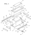
FIG. 3 is an exploded view of the body support system shown inFIG. 1 ; -
FIG. 4 is a right front perspective view of a second configuration of a body support system; -
FIG. 5 is a front view of the body support system shown inFIG. 4 ; -
FIG. 6 is a cross-sectional view of the body support system shown inFIG. 4 , taken along line 6-6 inFIG. 5 . -
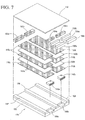
FIG. 7 is an exploded view of the body support system shown inFIG. 4 ; -
FIG. 8 is a right front perspective view of a third configuration of a body support system; -
FIG. 9 is a cross-sectional view of the body support system shown inFIG. 8 , taken along line 9-9 ofFIG. 8 ; -
FIG. 10 is an exploded view of the body support system shown inFIG. 8 ; -
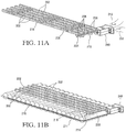
FIG. 11A is a rear perspective view of the internal air flow guides and air flow unit shown inFIG. 10 ; -
FIG. 11B is a rear perspective view of the internal air flow guides and air flow unit shown inFIG. 10 coupled to fluid cells; and -
FIG. 12 is a graph of Combined Heat Flux and Evaporative Capacity data for one body support system according to the invention. -
FIGs. 1-11B show various configurations ofbody support systems - Indentation Force Deflection (hereinafter "IFD") is a measure of foam stiffness and is frequently reported in pounds of force (Ibf). This parameter represents the force exerted when foam is compressed by 25% with a compression platen. One procedure for measuring IFD is set forth in ASTM D3574. According to this procedure, for IFD25 at 25%, foam is compressed by 25% of its original height and the force is reported after one minute. Foam samples are cut to a size of 15"×15"×4" (0.38m x 0.38m x 0.1 m) prior to testing.
- Air permeability for foam samples typically is measured and reported in cubic feet per square foot per minute (ft3/ft2/min). One method of measuring air permeability is set forth in ASTM 737. According to this method, air permeability is measured using a Frazier Differential Pressure Air Permeability Pressure machine. Higher values measured, using this type of machine, translate to less resistance to air flow through the foam.
- "Heat Withdrawal Capacity" refers to the ability to draw away heat from a support surface upon direct or indirect contact with skin. "Evaporative Capacity" refers to the ability to draw away moisture from a support surface or evaporate moisture at the support surface. Both of these parameters, therefore, concern capability to prevent excessive buildup of heat and/or moisture at one or more support surfaces. The interface where a body and support surface meet may also be referred to as a microclimate management site, where the term "microclimate" is defined as both the temperature and humidity where a body part and the support surface are in contact (i.e. the body-support surface interface). Preferably, the measurement and calculation of Heat Withdrawal Capacity and Evaporative Capacity are conducted according to standards issued by the Rehabilitation Engineering and Assistive Technology Society of North America ("RESNA").
- Turning in detail to the drawings,
FIGs. 1-3 show a first configuration of abody support system 10. Thesystem 10 may be assembled for use as a mattress, which in this example is particularly suited for medical environments that care for long-term care patients with limited mobility. Mattresses used in these types of environments, typically have a maximum overall thickness of about 6 (six) inches (0.15m). Thebody support system 10 in this example comprises layers in stacked relation to support an individual person or patient. The configuration and orientation of these layers is described herein. - The
body support system 10 includes a plurality of uppermost comfort layers 12, with each layer having afoam support surface 14. Thefoam support surface 14 forms an upper or top surface of the body support system. Eachfoam support surface 14 comes into direct or indirect contact with a body of an individual person or patient (not shown) when the body is in a partial or full seated or lying position. In this system configuration, the plurality of uppermost comfort layers 12 are coupled to internal air flow guides 16 (FIGs. 2 and3 ) to form anair flow path 18 from anair inlet 20 to anair outlet 22. Theair inlet 20 andair outlet 22 are disposed within thebody support system 10 in a central core 13 positioned below, and adjacent to, the uppermost comfort layers 12 for the embodiment shown inFIGs. 1-3 . The central core 13 is an area positioned between theuppermost comfort layer 12 and a bottommost layer of the body support system. By forming theair flow path 18 within the core of the body support system, air and moisture may be drawn away from one or more foam support surfaces, as further described in the Examples below. - The uppermost comfort layers 12 are formed of a cellular polymer, such as an open cell polyurethane foam. The uppermost comfort layers 12 comprise a temperature and pressure sensitive cellular polymer materials. Such structures include viscoelastic open cell polyurethane foams that optionally are reticulated. Viscoelastic open cell polyurethane foams have the ability conform to body contours when subjected to compression from an applied load and then slowly return to their original uncompressed state, or close to their uncompressed state, after removal of the applied load. One definition of viscoelastic foam is derived by a dynamic mechanical analysis that measures the glass transition temperature (Tg) of the foam. Nonviscoelastic resilient polyurethane foams, based on a 3000 molecular weight polyether triol, generally have glass transition temperatures below -30 °C, and possibly even below -50 °C. By contrast, viscoelastic polyurethane foams have glass transition temperatures above -20 °C. If the foam has a glass transition temperature above 0 °C, or closer to room temperature (e.g., room temperature (20 °C)), the foam will manifest more viscoelastic character (i.e., slower recovery from compression) if other parameters are held constant.
- In addition, in some configurations, at least a portion of an uppermost comfort layer is reticulated. Reticulated polyurethane foam materials include those materials manufactured using methods that remove or break cell windows. Various mechanical, chemical and thermal methods for reticulating foams are known. For example, in a thermal method, foam may be reticulated by melting or rupturing the windows with a high temperature flame front or explosion, which still leaves the strand network intact. Alternatively, in a chemical method the cell windows may be etched away using the hydrolyzing action of water in the presence of an alkali metal hydroxide. If a polyester polyurethane foam has been made, such foam may be chemically reticulated to remove cell windows by immersing a foam slab in a heated caustic bath for from three to fifteen minutes. One possible caustic bath is a sodium hydroxide solution (from 5.0 to 10.0 percent, preferably 7.5% NaOH) that is heated to from 70°F to 160° F (21°C to 71°C), preferably from 120° F to 160° F (49°C to 71°C.). The caustic solution etches away at least a portion of the cell windows within the foam cellular structure, leaving behind hydrophilic ester polyurethane foam.
- Materials used for the uppermost comfort layers may be classified as low air loss materials. Materials of this type are capable of providing air flow to a support surface for management of heat and humidity at one or more microclimate sites.
- In the
body support system 10 shown inFIGs. 1-3 , the plurality of uppermost comfort layers 12 includes a head and neck supportingcomfort layer 24, side comfort layers 26a, 26b, a central torso supportingcomfort layer 28, and a heel supportingcomfort layer 30. Each of these respective layers is positioned within thebody support system 10 for support of a body in a supine position. The head and neck supportingcomfort layer 24 is positioned within thesystem 10 for support of a head and neck. The side comfort layers 26a, 26b are positioned within the system for support of upper extremities (i.e., arms). The central torso supportingcomfort layer 28 is positioned within the system for support of the upper and lower torso. And, the heel supportingcomfort layer 30 is positioned within thesystem 10 for support of the lower extremities (i.e., feet and ankles). Each respective comfort layer has a density ranging from about 1.5 pounds per cubic foot (lb/ft3) (24.03 kg/m3) to about 8.0 lb/ft3 (128.15 kg/m3), and preferably from about 3.0 lb/ft3 (48.06 kg/m3) to about 5.0 lb/ft3 (80.09 kg/m3). In addition, each respective comfort layer has an IFD25 ranging from about 5 pounds-force (Ibf) (22.24 N) to about 20 Ibf (88.96 N), and preferably from about 8 Ibf (35.59 N) to about 15 Ibf (66.72 N). - In addition to the properties referred to above, the central torso supporting
comfort layer 28 also may have a substantially porous and air permeable structure. In preferred embodiments, the central comfort layer has a porosity ranging from about 65 pores per inch (ppi) to about 75 ppi and air permeability values ranging from about 150 cubic feet per square foot per minute (ft3/ft2/min) to 350 ft3/ft2/min. Because thecentral comfort layer 28 includes a centraluppermost foam surface 31 that contacts heavier body parts, e.g., buttocks, hips, thighs, which are very susceptible pressure ulcer formation, increased porosity and air permeability in these areas can be beneficial. The increased porosity and air permeability further allows for added control of Heat Withdrawal Capacity and Evaporative Capacity, as further described below. - Adjacent to the plurality of uppermost comfort layers 12 is a plurality of foam surrounds or rails 32. The foam surrounds or rails 12 generally are firmer than other portions of the construction to support an individual when sitting at the side or end of the mattress. The plurality of foam surrounds or rails 32 includes a
foot rail 34, ahead rail 36, aleft side rail 38a and a right side rails 38b. As shown inFIG. 3 , the left andright side rails upper side rail 40, amiddle side rail 42, and alower side rail 44, which are joined together or adhered to each other. Defined within each left andright side rail cavities 46 for insertion of one or moreair flow units 48. Alternatively, the left and right side rails may be formed as one-piece structures into whichcavities 46 are defined within the side rails for receiving theair flow units 48. Eachrail 32 included in the plurality of foam surrounds or rails has a density ranging from about 1.0 lb/ft3 (16.02 kg/m3) to about 3.0 lb/ft3 (48.06 kg/m3), and preferably from about 2.4 lb/ft3 (38.44 kg/m3) to about 2.8 lb/ft3 (44.85 kg/m3). In addition, each respective foam surround or rail has an IFD25 ranging from about 5 Ibf (22.24 N) to about 250 Ibf (1112.06 N) and preferably from about 50 Ibf (222.41 N) to about 70 Ibf (311.38 N). - One or more
air flow units 48 are disposed within thebody support system 10 to facilitate air flow along one or moreair flow paths 18, depending upon the positioning of air inlets and air outlets within thesystem 10. Both air inlets and air outlets may be defined in one ormore cavities 46 positioned within the system.Air flow units 48 may be configured to generate air flow using either positive or negative pressure. One type of suitable air flow unit is a 12V DC Blower sold by Delta Electronics. The use ofair flow units 48 facilitates withdrawal from and removal of moisture and heat at foam support surfaces 14 for control of both Heat Withdrawal Capacity and Evaporative Capacity of one or more foam support surfaces of thebody support system 10. - As shown in
FIGs. 1- 3 , oneair flow unit 48 is disposed within thesystem 10 and seats within an internal portion of thebody support system 10. However, in other system configurations, one or more air flow units may be either internal or external to the system, and if external to the system, include one or more connecting members (not shown) such as tubing or piping. In alternative system configurations one or more air flow units also may be mounted in an accessible location near or adjacent the system. Suitable locations include, but are not limited to, portions of a bedframe, such as a drawer, support leg, headboard, footboard, or cabinets, or shelving coupled to the body support system. - An
air flow unit 48 may include ascreen 50 coupled to a filter (not shown), which in combination are used to filter particles, spores, bacteria, etc., which would otherwise exit thebody support system 10 into the room air throughair flow unit 48. During operation, theair flow unit 48 may operate to reduce and/or increase pressure within the system to facilitate air flow alongair flow paths 18 from anair inlet 20 to anair outlet 22. Regardless of the placement of anair flow unit 48 within the system, it should be configured to exhaustair 52 to the surrounding environment, as particularly shown inFIG. 1 . - Optionally, a pillow or plug (not shown) may fill any
cavity 46 of thebody support system 10 when theair flow unit 48 is removed and the body supporting system is used in a static condition (i.e., without air flow through the core of the body support system). - The
body support system 10 may be encased in a protective, waterproof, moisture vapor permeable cover (not shown), such as fabric laminate constructions incorporating polyurethane coatings or expanded polytetrafluoroethylene (ePTFE) When in use, thebody support system 10 may be covered by a textile bedding sheet (not shown). - A
wireless controller 54 also may be used to control various aspects of thesystem 10. For example, a wireless controller may control the level and frequency, rate, duration, and amplitude of air flow and pressure that travels through the system. A wireless controller also may include one or more alarms to alert a patient or caregiver of excessive use of pressurized air, synchronization issues and power failure at surface power unit. In addition, a wireless controller also may be used to vary positioning of the body support system if the system is so configured to fold or bend - Referring particularly to
FIGs. 2 and3 ,air flow paths 18 are further facilitated by the arrangement of an internal air flow guide 16 within thesystem 10. The internal air flow guide 16 facilitates air flow from theair inlet 20 to theair outlet 22. The internal air flow guide 16 can include multiple portions or be manufactured from a singular piece of air permeable material. Where multiple portions are used, each respective piece of air permeable material is coupled either to a comfort layer, or to an air inlet, or to an air outlet, such that the entire internal air flow guide 16 forms a discrete pathway to direct air and/or moisture vapor flow through the internal core of thebody support system 10. - The internal air flow guide 16 comprises an
upper body portion 16a, acentral body portion 16b, and alower body portion 16c, as shown particularly inFIG. 2 . Each of theserespective portions body support system 10 at locations corresponding to the locations that support a person's upper body (e.g., head and neck), central body (e.g., upper and lower torso), and lower body (e.g., lower extremities), respectively. Where multiple air flow guides are disposed within thesystem 10, theupper body portion 16a may be adjacent to the central body portion (FIG. 2 ) or positioned vertically higher relative to thelower body portion 16c. In addition, thecentral body portion 16b may be positioned vertically higher relative to thelower body portion 16c. As such, the arrangement of the multiple portion internal air flow guides, as shown in theFIGs. 1-3 , is not to be construed as limiting. However, one or more internal air flow guides, preferably are positioned within thebody support system 10 to fulfill competing functions of pressure redistribution, moisture withdrawal/evaporation and heat withdrawal from the one or more foam support surfaces 14. - Materials used to manufacture an internal air flow guide, therefore, have physical properties that relieve pressure and facilitate air flow. Preferably, the internal air flow guide(s) comprise open cell polyurethane foams that have been reticulated. Singular or multiple internal air flow guides formed from cellular polymer material(s) preferably have a foam density of ranging from about 1.3 lb/ft3 (20.82 kg/m3) to about 2.5 lb/ft3 (40.05 kg/m3), and preferably from about 1.6 lb/ft3 (25.63 kg/m3) to about 2.2 lb/ft3 (35.24 kg/m3). In addition, each respective air flow guide formed from cellular polymer material(s) has an IFD ranging from about 10 lbf (44.48 N) to about 80 lbf (355.86 N), and preferably from about 25 lbf (111.21 N) to about 40 lbf (177.93 N). Porosity of singular or multiple internal air flow guides formed from cellular polymer material(s) preferably ranges from about 10 ppi to about 30 ppi.
- The
body support system 10 also includes a plurality of additional support layers 60 positioned under the internal air flow guide 16 for further support of a body in a supine position. The plurality of support layers 60 includes anupper support layer 62, acentral support layer 64, alower support layer 66, and afoundation support layer 68. Support layers 62, 66, 68 may be formed from open cell polyurethane foam having a density ranging from about 1.0 lb/ft3 (16.02 kg/m3) to about 3.0 lb/ft3 (48.06 kg/m3), and preferably from about 2.4 lb/ft3 (38.44 kg/m3) to about 2.8 lb/ft3 (44.85 kg/m3). In addition, eachsupport layer lower support layer 66 is preferably "soft" or "softer", such that placement of a foot is particularly comfortable when the body is in a fully supine position. The density of cellular polymer material forming thelower support layer 66 ranges from about 1.0 lb/ft3 (16.02 kg/m3) to about 1.3 lb/ft3 (20.82 kg/m3) and the IFD25 of the cellular polymer material forming thelower support layer 66 preferably ranges from about 10 lbf (44.48 N) to about 20 lbf (88.96 N).Support layer 64 may be formed from open cell polyurethane foam having a density ranging from about 1.4 lb/ft3 (22.43 kg/m3) to about 2.0 lb/ft3 (32.04 kg/m3). In addition, thecentral support layer 64 of cellular polymer material preferably has an IFD25 ranging from about 5 Ibf (22.24 N) to about 250 Ibf (1112.06 N) and preferably from about 30 Ibf (133.45 N) to about 40 Ibf (177.93 N). -
FIGs. 4-7 show a second configuration of abody support system 100. Thesystem 100 may be assembled for use as a mattress, which is particularly suited for home environments of those with limited mobility, e.g., elderly and disabled persons who are susceptible to pressure ulcers. This system configuration is further designed as a multi-zone system, which is suited to support two reclining bodies (not shown) that lay longitudinally along the length of the system in fully or partially supine positions. Support surfaces in multi-zoned systems, such as that shown inFIGs. 4-7 , include a plurality of segments that have different pressure redistribution capabilities. - As shown particularly in
FIGs. 4 and 5 , thebody support system 100 defines a left-side zone 170a and a right-side zone 170b. These zones are respectively arranged within thesystem 100 and coupled to internal air flow guides 116a, to form anair flow paths air inlets air outlets air inlets 120 and air outlets 122 are disposed within cavities formed in thebody support system 100. By forming theair flow paths system 100 is able to withdraw heat and withdraw or evaporate moisture away from thefoam support surface 114. The material forming theairflow paths body support system 100. To fulfill these competing functions, thebody support system 100 includes anuppermost comfort layer 112, a central core and afoundation 190. The central core is defined as the area between theuppermost comfort layer 112 and the bottommost layer, i.e. thefoundation 190. Included within the central core are theinternal comfort layers air flow blocks air flow block inner support blocks external support blocks foundation 190. - The
uppermost comfort layer 112 and theinternal comfort layers - The internal air flow guides 116a, 116b and the
air flow blocks - Referring to
FIGs. 6 and7 ,support blocks foundation 190 are positioned under the internal air flow guides 116a, 116b and the airflow support blocks foundation 190 includes twoouter supports medial support 196, and a bottom support layer 198. Defined within the bottom support layer are twocavities air flow units - Two
air flow units air flow paths exhaust air 152 to the surrounding environment.Air flow units foam support surface 114. In other system configurations (not shown),air flow unit system 100 and include one or more connecting members (not shown), such as tubing or piping. Alternatively,air flow units screen wireless controller 154 also may be used for control of various aspects of thesystem 100, as described with reference to thefirst system configuration 10. -
FIGs. 8-11B show a third configuration of abody support system 200. This system configuration also may be assembled for use as a mattress, which is particularly suited for home environments of those with limited mobility, e.g., elderly and disabled persons who are susceptible to pressure ulcers. Mattresses used in these types of environments, typically have a maximum overall thickness of about 14 inches (0.36 m). This system configuration includes anuppermost comfort layer 212, a central core, and afoundation support layer 268. The central core is defined as the area between theuppermost comfort layer 212 and the bottommost layer, i.e. thefoundation support layer 268. As such, the central core includes a plurality offluid cells 211, a plurality of internal air flow guides 216, asurround 232, anupper support layer 262, and acentral support 264. This type of system may be considered a hybrid static and dynamic system because it includes materials that conform to body contours and includes alternating pressure elements. - The
body support system 200 includes a singularuppermost comfort layer 212, having afoam support surface 214 that comes into direct or indirect contact with a body (not shown) when the body is in a partially or fully seated or lying position on thebody support system 200. In this system configuration, theuppermost comfort layer 212 is coupled to and positioned over internal air flow guides 216 (FIGs. 9 and10 ) to form a plurality ofair flow paths 218 within thesystem 200. Anair flow unit 248 is disposed within the body support system to establish negative pressure to draw air and moisture vapor through the internal air flow guides 216 along the plurality ofair flows paths 218. This type ofair flow unit 248 is also configured to generate air flow andexhaust air 252 to an air outlet 222, using either positive or negative pressure. Therefore, air within the system is drawn through the plurality of internal air flow guides 216 thereby to draw moisture and heat away from thefoam support surface 214. - As shown particularly in
FIGs. 10 and11A , the plurality of internal air flow guides 216 includes longitudinal air flow guides 202 and a transverseair flow guide 204. Each longitudinalair flow guide 202 extends lengthwise to correspond generally to the length of at least one body in a supine position on thebody support system 200. The transverseair flow guide 204 is coupled to abottom surface 206 at anend 208 of each longitudinalair flow guide 202, as shown inFIG. 11A . In this configuration, the transverseair flow guide 204 is positioned within aridge 215 between two fluid cells. The materials forming the plurality of air flow guides 216 also facilitate air flow because of their physical properties. For example, a cellular polymer material such as reticulated open cell polyurethane foam may be used to form the air flow guides 216 and the transverseair flow guide 204. Each air flow guide may be formed of a cellular polymer with a density ranging from about 1.3 lb/ft3 (20.82 kg/m3) to about 2.5 lb/ft3 (40.05 kg/m3), and preferably from about 1.6 lb/ft3 (25.63 kg/m3) to about 2.2 lb/ft3 (35.24 kg/m3). In addition, each respective air flow guide may be formed of a cellular polymer with an IFD25 ranging from about 10 Ibf (44.48 N) to about 80 lbf (355.86 N) and preferably from about 25 lbf (111.21 N) to about 40 lbf (177.93 N), and porosity ranging from about 10 ppi to about 30 ppi. - The
surround 232 may be a unitary piece or separate pieces that include a foot rail, a head rail, and side rails. As shown particularly inFIG. 10 , acavity 246 may be defined within the surround 242 to accommodate anair flow unit 248 within thesystem 200. The surround preferably is formed of a cellular polymer material that has a density ranging from about 1.0 lb/ft3 (16.02 kg/m3) to about 3.0 lb/ft3 (48.06 kg/m3), and preferably from about 2.4 lb/ft3 (38.44 kg/m3) to about 2.8 lb/ft3 (44.85 kg/m3). In addition, each respective comfort layer may be formed of a cellular polymer material that has an IFD25 ranging from about 5 lbf (22.24 N) to about 250 lbf (1112.06 N) and preferably from about 50 lbf (222.41 N) to about 70 lbf (311.38 N). - In the system configuration shown in
FIGs. 8-11B , the central support includescells 211 filled with fluids, such as air. The cells may be inflated or pressurized usingair flow units 248 within the system, or other source(s) external to the system. Preferably, awireless controller 254 is coupled to thesystem 200 to inflate and deflatecells 211 either independently, in predetermined patterns, or in unison. The wireless controller may be programmed to alternate inflation and deflation cycles. Cycling times can vary, depending upon body structures and needs of the patients, as determined by a health care professional or caregiver. Preferably, however, the cycles used vary slowly over time for user comfort. - As particularly shown in
FIGs.11A and 11B , in this system configuration both the plurality ofcells 211 and the transverseair flow guide 204 are connected to anair flow unit 248. Thus, theair flow unit 248 is disposed within the body support system to draw air through the plurality of air flow guides 216, creatingair flows paths 218, as well as to inflate and deflatecells 211, using either negative pressure (for drawing air through the air flow guides or deflating the cells) or positive pressure for inflating the cells. In this configuration, the plurality ofcells 211 may include afluid entry cell 209 and afluid conduit 215, which are coupled to other support cells 217 for inflation and deflation. Pressure is therefore controlled through the use of both internal air flow guides and the plurality ofcells 211 disposed within thesystem 200. - The
upper support layer 262,central support layer 264, andfoundation support layer 268 are positioned within thesystem 200 for further support of a body in a supine position. Defined within theupper support layer 262 arechannels 213 used to align the longitudinal air flow guides 202 such that theguides 202 are coupled to the uppermost comfort layer 212 (FIG. 9 ) upon assembly. Theupper support layer 262 and other comfort layers in the construction are formed of a viscoelastic cellular polymer material, such as an open cell polyurethane foam, and have a density ranging from about 1.5 lb/ft3 (24.03 kg/m3) to about 8.0 lb/ft3 (128.15 kg/m3), and preferably from about 3.0 lb/ft3 (48.06 kg/m3) to about 5.0 lb/ft3 (80.09 kg/m3). In addition, theupper support layer 262 preferably has an IFD25 ranging from about 5 lbf (22.24 N) to about 20 lbf (88.96 N), and more preferably from about 8 lbf (35.59 N) to about 15 lbf (66.72 N). Thefoundation support layer 268 preferably is formed of a cellular polymer material that has a density ranging from about 1.0 lb/ft3 (16.02 kg/m3) to about 3.0 lb/ft3 (48.06 kg/m3), and preferably from about 2.4 lb/ft3 (38.44 kg/m3) to about 2.8 lb/ft3 (44.85 kg/m3). In addition, thefoundation support layer 268 may be formed of a cellular polymer material that has an IFD25 ranging from about 5 lbf (22.24 N) to about 250 lbf (1112.06 N), and preferably from about 50 lbf (222.41 N) to about 70 lbf (311.38 N). - One or more of the elements included within each
respective system - The following examples were performed to measure Evaporative Capacity and Heat Loss (i.e., heat withdrawal) of foam support surfaces. The following testing conditions, therefore, were meant to simulate body loading conditions of foam testing support surface(s), having a flat profile, as particularly shown in
body support systems - Testing equipment included: (1) a conditioned foam testing support surface; (2) a measuring unit configured to control temperature and water supply on the foam testing support surface; (3) a thermal guard; (4) bedding and (5) weights.
- For this test, the conditioned foam testing support surface was the uppermost surface of a foam mattress having a structure comparable to that shown in
FIGs. 1-3 . The support surface was conditioned in a testing environment having a temperature and humidity of 21 ±2 °C and RH at 50 ± 10%. - The measuring unit included a metallic test plate, a heating element block with an internal heating element, and a temperature controller with a temperature sensor.
- The thermal guard included a high thermal conductivity material with heating elements, a thermal guard temperature sensor, and a controller used to maintain the thermal guard temperature and the measuring unit at the same level. The thermal guard was used to prevent heat leakage from the measuring unit.
- Bedding included a standard cotton bed sheet that covered the testing support surface, and a medium-weight cotton blanket over the cotton bed sheet.
- Weights were used to maintain an average interface pressure over at the body-support surface interface between 0.5 psi (34.47 mBar) and 0.7 psi (48.26 mBar).
- Testing was performed over approximately a two-hour period and variables determined, according to the following:
- (1) Measurement of Dry Heat Flux (Qdry), where Qdry is defined as the heat flow per unit area from warmed the test plate into the cooler environment in response to the difference in temperature. This value is considered equivalent to a surface's ability to ward off heat accumulation on the skin in the absence of moisture; This parameter is expressed in terms of W/m2.
- (2) Measurement of Combined Heat Flux (Qwet), where Qwet is the heat flow per unit area from a wetted test plate into the environment. This parameter relates to surface's ability to ward off heat accumulation on skin in the presence of moisture. This parameter also is expressed in terms of W/m2.
- (3) Calculation of Thermal Resistance (Rdry);
- (4) Determination of Partial Pressure of Ambient Air (Pa ) and Saturation Pressure of Measurement Plate (Pm );
- (5) Calculation of Apparent Evaporative Resistance (Rwet);
- (6) Calculation of Apparent Evaporative Heat Flux (Qevap); and
- (7) Calculation of Evaporative Capacity (EvapCap), where EvapCap is defined as the rate at which a surface is capable of promoting the evaporation of the test plate. This parameter is expressed in terms of g/m2hr.
-
- a. The cotton bed sheet was positioned on the foam testing support surface of the mattress's uppermost comfort layer.
- b. The HOB elevation angle of the mattress was set at 0°.
- c. The measuring unit test plate was positioned in the sacral region of the foam testing support surface on top of the cotton bed sheet.
- d. Six regions of the foam support surface were identified for measurement.
- e. Weights were positioned on the measuring unit to load the unit to a mean pressure of about 0.5 psi (34.47 mBar).
- f. The measuring unit and the weights were covered with the medium-weight blanket.
- g. The test plate temperature was set to maintain 35 °C ± 2 °C.
- h. Over a 100-minute period, Qdry values were monitored and collected.
-
- a. The cotton bed sheet was positioned on the foam testing support surface of the mattress's uppermost comfort layer.
- b. The HOB elevation angle of the mattress was set at 0°.
- c. The measuring unit test plate was positioned in the sacral region of the foam testing support surface on top of the cotton bed sheet and also positioned to receive water flow.
- d. Six regions of the foam support surface were identified for measurement in accordance with RESNA standards.
- e. Weighted bags were positioned on the measuring unit to load the unit to a mean pressure of about 0.5 psi (34.47 mBar).
- f. The measuring unit and the weighted bags were covered with the medium-weight blanket.
- g. The test plate temperature was set to maintain 35 °C ± 2 °C.
- h. Over approximately a 60-minute period, Qwet values were monitored and collected.
- Thermal resistance (Rdry) was calculated according to the following formula:

- Full saturation (Psat) (i.e., at 100% relative humidity) was determined from a saturated steam table. Partial Pressure (Pa) (except for full saturation) was determined by multiplying Saturated Pressure (Psat) at specific temperatures by relative humidity (RH%).
- Apparent Evaporative Resistance (Rwet) was calculated according to the following formula:

- Evaporative Heat Flux (Qevap) was calculated according to the following formula:

- Evaporative Capacity was calculated according to the following formula:

Representative Data: Time (min) Qdry Qwet Rdry Rwet Qevap EvapCap 0.00 40.83 345.87 0.34 11.61 308.66 459.90 2.00 41.02 135.77 0.34 31.76 94.94 141.46 4.00 39.26 103.49 0.36 41.31 63.56 94.70 6.00 39.76 97.23 0.36 43.73 57.97 86.37 8.00 40.61 96.91 0.35 44.03 57.00 84.93 10.00 41.32 96.43 0.34 44.50 55.70 82.99 12.00 42.11 96.66 0.32 44.34 55.17 82.20 14.00 41.03 96.85 0.33 44.65 54.67 81.45 16.00 41.31 99.93 0.32 43.91 57.18 85.20 18.00 40.76 100.90 0.33 43.95 57.61 85.84 20.00 41.10 100.66 0.33 43.90 57.00 84.93 22.00 41.99 101.55 0.33 44.04 57.60 85.82 24.00 40.37 104.60 0.35 42.72 60.46 90.09 26.00 41.01 101.83 0.34 43.77 57.89 86.26 28.00 40.33 102.79 0.35 41.35 59.68 88.92 30.00 40.82 101.57 0.34 42.05 59.32 88.38 40.00 41.66 103.23 0.32 41.81 60.75 90.52 50.00 42.72 103.63 0.33 42.39 61.24 91.25 59.00 41.88 101.57 0.31 43.10 59.79 89.08 -
Figure 12 shows a graph of Qwet and EvapCap data for a mattress of a configuration as shown inFIGs. 1-3 measured over a period of approximately 120 minutes. - Thus, various configurations of body support systems are disclosed. While embodiments of this invention have been shown and described, it will be apparent to those skilled in the art that many more modifications are possible without departing from the inventive concepts herein. Moreover, the examples described herein are not to be construed as limiting. The invention, therefore, is not to be restricted except in the spirit of the following claims.
Claims (9)
- A body support system (10) for support of a person's body in a supine position, the body having a torso, the body support system (10), comprising:at least one uppermost comfort layer (12) having a support surface (14) and disposed above a central core (13) of the body support system (10), the at least one uppermost comfort layer (12) comprising a temperature and pressure sensitive cellular polymer material, the central core (13) being an area positioned between the at least one uppermost comfort layer (12) and a bottommost layer (68) of the body support system (10);an air flow guide (16) disposed within the central core (13) of the body support system (10),the air flow guide (16) comprising a central body portion (16b), a lower body portion (16c), and an upper body portion (16a), said central body portion (16b), lower body portion (16c) and upper body portion (16a) being positioned within the body support system (10) at a location corresponding to the location intended to support a person's central body, lower body and upper body, respectively,wherein the upper body portion (16a) of the air flow guide (16) is positioned vertically higher relative to the lower body portion (16c) of the air flow guide (16),wherein the air flow guide (16) is manufactured from a low air loss material, andwherein the air flow guide (16) forms a discrete air flow path (18) to direct air and/or moisture vapor flow through the central core (13) of the body support system (10);a plurality of support layers (60) positioned under the air flow guide (16), the plurality of support layers (60)including an upper support layer (62), a central
support layer (64), a lower support layer (66), and a foundation support layer (68), wherein the foundation support layer (68) is the bottommost layer of the body support system (10), andwherein the central support layer (64) has a density range from about 22,43 kg/m3 to about 32,04 kg/m3, and the lower support layer (66) has a density range from about 16,02 kg/m3 to about 20,82 kg/m3; andat least one air flow unit (48), disposed within an internal portion of the body support system (10),wherein during operation, the at least one air flow unit (48) facilitates withdrawal from and removal of moisture and heat at the foam support surface (14) such that the at least one air flow unit (48) operates to reduce and/or increase pressure within the body support system (10) to facilitate air flow along the air flow path (18) from an air inlet (20) to an air outlet (22) disposed within the body support system (10) in a central core (13) positioned below, and adjacent to, the at least one uppermost comfort layer (12). - The body support system (10) of claim 1, characterized in that the temperature and pressure sensitive cellular polymer material comprises viscoelastic open cell polyurethane foam.
- The body support system (10) of claim 2, characterized in that the viscoelastic open cell polyurethane foam is reticulated.
- The body support system (10) of any one of claims 1-3, characterized in that the air flow guide (16) comprises a material selected from the group consisting of: cellular polymer, reticulated open cell polyurethane foam, nonwoven fibrous batt, reticulated rebonded polyurethane foam, and polyamide.
- The body support system (10) of any one of claims 1-4, characterized in that the air flow path (18) extends from an inlet (20) disposed in the body support system (10), through the air flow guide (16) and out of the air control unit (48), with said inlet (20), air flow guide (16) and air control unit (48) all being disposed under the uppermost comfort layer (12).
- The body support system (10) of any one of claims 1-5, characterized in that moisture vapor is evacuated from the uppermost comfort (12) layer at an Evaporative Capacity in the range of about 10 gm2/hr. to about 150 gm2/hr.
- The body support system (10) of any one of claims 1-6, characterized in that heat is withdrawn from the uppermost comfort layer (12) at a Heat Withdrawal Capacity in the range from about 10 W/m2 to about 300 W/m2.
- The body support system (10) of any one of claims 1-7, characterized in that the body support system (10) is encased in a protective, waterproof, moisture vapor permeable cover.
- The body support system (10) of any one of claims 1-8, wherein the central body portion (16b) of the air flow guide (16) is positioned vertically higher relative to the lower body portion (16c) of the air flow guide (16).
Applications Claiming Priority (2)
| Application Number | Priority Date | Filing Date | Title |
|---|---|---|---|
| US13/744,940 US9392875B2 (en) | 2013-01-18 | 2013-01-18 | Body support system with combination of pressure redistribution and internal air flow guide(s) for withdrawing heat and moisture away from body reclining on support surface of body support system |
| PCT/US2013/075375 WO2014113164A1 (en) | 2013-01-18 | 2013-12-16 | Body support system with pressure redistribution and internal air flow guide(s) |
Publications (2)
| Publication Number | Publication Date |
|---|---|
| EP2945587A1 EP2945587A1 (en) | 2015-11-25 |
| EP2945587B1 true EP2945587B1 (en) | 2017-03-22 |
Family
ID=49943520
Family Applications (1)
| Application Number | Title | Priority Date | Filing Date |
|---|---|---|---|
| EP13818885.9A Active EP2945587B1 (en) | 2013-01-18 | 2013-12-16 | Body support system with pressure redistribution and internal air flow guide(s) |
Country Status (3)
| Country | Link |
|---|---|
| US (1) | US9392875B2 (en) |
| EP (1) | EP2945587B1 (en) |
| WO (1) | WO2014113164A1 (en) |
Cited By (1)
| Publication number | Priority date | Publication date | Assignee | Title |
|---|---|---|---|---|
| RU222852U1 (en) * | 2023-05-15 | 2024-01-22 | Владимир Викторович Михайлов | ORTHOPEDIC MATTRESS |
Families Citing this family (38)
| Publication number | Priority date | Publication date | Assignee | Title |
|---|---|---|---|---|
| AU2009270757B2 (en) | 2008-07-18 | 2016-05-12 | Gentherm Incorporated | Climate controlled bed assembly |
| US20130212808A1 (en) | 2012-02-21 | 2013-08-22 | Charles A. Lachenbruch | Topper with Targeted Fluid Flow Distribution |
| US9138064B2 (en) | 2013-01-18 | 2015-09-22 | Fxi, Inc. | Mattress with combination of pressure redistribution and internal air flow guides |
| CA2936688C (en) | 2014-01-13 | 2021-11-30 | Bedgear, Llc | Ambient bed having a heat reclaim system |
| US9717638B2 (en) * | 2014-03-10 | 2017-08-01 | Span-America Medical Systems, Inc. | Self-powered microclimate controlled mattress |
| US9888785B2 (en) | 2014-04-21 | 2018-02-13 | Casper Sleep Inc. | Mattress |
| GB201509041D0 (en) * | 2015-05-27 | 2015-07-08 | Park House Healthcare Ltd | Reversible cushion means and methods of manufacture and use thereof |
| US10765577B2 (en) | 2015-06-30 | 2020-09-08 | Hill-Rom Services, Inc. | Microclimate system for a patient support apparatus |
| US10624804B2 (en) | 2015-08-18 | 2020-04-21 | Hill-Rom Services, Inc. | Microclimate management airflow control based on incontinence detection |
| WO2018022760A1 (en) * | 2016-07-27 | 2018-02-01 | Philip Sherman | Climate controlled mattress system |
| US10827845B2 (en) | 2017-02-24 | 2020-11-10 | Sealy Technology, Llc | Support cushions including a support insert with a bag for directing air flow, and methods for controlling surface temperature of same |
| RU2757837C2 (en) | 2017-04-10 | 2021-10-21 | Бедгир, Ллк | Mattress system with negative pressure |
| WO2019036393A1 (en) | 2017-08-14 | 2019-02-21 | Casper Sleep Inc. | Mattress Containing Ergonomic and Firmness-Regulating Endoskeleton |
| US10797524B2 (en) | 2017-10-24 | 2020-10-06 | Stryker Corporation | Techniques for power transfer through wheels of a patient support apparatus |
| US10910888B2 (en) | 2017-10-24 | 2021-02-02 | Stryker Corporation | Power transfer system with patient transport apparatus and power transfer device to transfer power to the patient transport apparatus |
| US11394252B2 (en) | 2017-10-24 | 2022-07-19 | Stryker Corporation | Power transfer system with patient support apparatus and power transfer device to transfer power to the patient support apparatus |
| US11139666B2 (en) | 2017-10-24 | 2021-10-05 | Stryker Corporation | Energy harvesting and propulsion assistance techniques for a patient support apparatus |
| US11389357B2 (en) | 2017-10-24 | 2022-07-19 | Stryker Corporation | Energy storage device management for a patient support apparatus |
| US11540964B2 (en) | 2018-02-27 | 2023-01-03 | Hill-Rom Services, Inc. | Patient support surface control, end of life indication, and x-ray cassette sleeve |
| US11241100B2 (en) | 2018-04-23 | 2022-02-08 | Casper Sleep Inc. | Temperature-regulating mattress |
| US11160386B2 (en) | 2018-06-29 | 2021-11-02 | Tempur World, Llc | Body support cushion with ventilation system |
| WO2020008401A1 (en) * | 2018-07-04 | 2020-01-09 | New Zealand Comfort Group Limited | A mattress or topper with heat dissipation configuration and method of manufacture |
| WO2020023605A1 (en) * | 2018-07-27 | 2020-01-30 | Bedgear, Llc | Bedding system and method |
| KR102604935B1 (en) * | 2018-12-04 | 2023-11-22 | 엘지전자 주식회사 | Dryer for bed |
| JP6687769B1 (en) * | 2019-01-15 | 2020-04-28 | パラマウントベッド株式会社 | Air mattress |
| US11613189B2 (en) | 2019-06-28 | 2023-03-28 | Gentherm Incorporated | B-side distribution system |
| USD908398S1 (en) | 2019-08-27 | 2021-01-26 | Casper Sleep Inc. | Mattress |
| USD927889S1 (en) | 2019-10-16 | 2021-08-17 | Casper Sleep Inc. | Mattress layer |
| MX2022008234A (en) | 2020-01-03 | 2022-08-08 | Sleep Number Corp | Bed airflow and temperature control. |
| US11786046B2 (en) * | 2020-04-07 | 2023-10-17 | Lg Electronics Inc. | Bed |
| WO2022084798A1 (en) | 2020-10-23 | 2022-04-28 | Chambers George Allen | Three dimensional mattress system with environment control |
| US11678748B2 (en) | 2021-03-10 | 2023-06-20 | Pure-Development 1 B.V. | Upholstery support arrangement, including airflow arrays for conditioned furniture, and associated systems and methods |
| US12022955B2 (en) | 2021-03-10 | 2024-07-02 | Pure-Development 1 B.V. | Environmentally conditioned furniture, and associated systems and methods |
| US11744378B2 (en) | 2021-03-10 | 2023-09-05 | Pure-Development 1 B.V. | Support construction for conditioned furniture, and associated systems and methods |
| US11779127B2 (en) * | 2021-03-10 | 2023-10-10 | Pure-Development 1 B.V. | Air handling unit for environmentally conditioned furniture, and associated systems and methods |
| CN117042654A (en) * | 2021-03-12 | 2023-11-10 | 数眠公司 | Integrated fan assembly for bed |
| KR20240090405A (en) * | 2021-10-13 | 2024-06-21 | 슬립 넘버 코포레이션 | Bed microclimate control using humidity measurements |
| USD1078013S1 (en) | 2022-12-20 | 2025-06-03 | John GENNARO | Bed fan |
Family Cites Families (92)
| Publication number | Priority date | Publication date | Assignee | Title |
|---|---|---|---|---|
| US2425655A (en) | 1944-03-22 | 1947-08-12 | Edwin H Tompkins | Therapeutic device |
| US3101488A (en) * | 1961-07-10 | 1963-08-27 | Peebles David Meade | Air purifying and ventilating means for beds |
| US3266064A (en) | 1963-03-29 | 1966-08-16 | Figman Murray | Ventilated mattress-box spring combination |
| US3486177A (en) * | 1966-09-20 | 1969-12-30 | Califoam Corp Of America | Cushions |
| US3644950A (en) | 1969-08-01 | 1972-02-29 | Milton Roy Co | Patient support system |
| GB1532219A (en) * | 1975-06-28 | 1978-11-15 | Howorth Air Eng Ltd | Mattress |
| JPS61290953A (en) | 1985-06-19 | 1986-12-20 | 富士電機株式会社 | Body support |
| US4825488A (en) | 1988-04-13 | 1989-05-02 | Bedford Peter H | Support pad for nonambulatory persons |
| ATE134114T1 (en) * | 1991-08-20 | 1996-02-15 | Jack Schwartz | MULTI-LAYER MATTRESS |
| US5325551A (en) | 1992-06-16 | 1994-07-05 | Stryker Corporation | Mattress for retarding development of decubitus ulcers |
| US5249319A (en) | 1992-09-09 | 1993-10-05 | Mellen Air Manufacturing, Inc. | Low air loss, pressure relieving mattress system |
| GB2290256B (en) | 1994-06-03 | 1997-10-29 | Fagerdala World Foams Ab | Laminated supports |
| US5493742A (en) | 1994-05-10 | 1996-02-27 | Lake Medical Products, Inc. | Ventilating air mattress with an inflating quilted pad |
| US8025964B2 (en) | 1994-06-03 | 2011-09-27 | Tempur World, Llc | Laminated visco-elastic support |
| US5566409A (en) | 1994-07-01 | 1996-10-22 | Klearman; Jeffrey D. | Modular air mattress |
| US5588811A (en) | 1994-07-14 | 1996-12-31 | Price Manufacturing, Inc. | Air bed diaphragm pump |
| US6721979B1 (en) | 1995-04-25 | 2004-04-20 | Kci Licensing, Inc. | Air bed with fluidized bead surface and related methods |
| US6584628B1 (en) | 1995-08-04 | 2003-07-01 | Hill-Rom Services, Inc. | Hospital bed having a rotational therapy device |
| US5991949A (en) | 1995-08-15 | 1999-11-30 | Foamex L.P. | Hoseless air bed |
| US5794289A (en) * | 1995-10-06 | 1998-08-18 | Gaymar Industries, Inc. | Mattress for relieving pressure ulcers |
| US6115861A (en) * | 1997-10-09 | 2000-09-12 | Patmark Company, Inc. | Mattress structure |
| US5882349A (en) | 1995-12-26 | 1999-03-16 | Geomarine Systems, Inc. | Patient moisture control support surface coverlet |
| US6591437B1 (en) | 1996-04-15 | 2003-07-15 | Kci Licensing, Inc. | Therapeutic mattress and built-in controls |
| DE19634430A1 (en) * | 1996-06-07 | 1997-12-11 | Wurz Dieter | Seat, back or couch upholstery |
| US5699570A (en) | 1996-06-14 | 1997-12-23 | Span-America Medical Systems, Inc. | Pressure relief valve vent line mattress system and method |
| US5745941A (en) | 1997-02-13 | 1998-05-05 | Foamex L.P. | Air support mattress overlay with fitted sheet mounting |
| US6484334B1 (en) | 1997-11-07 | 2002-11-26 | Hill-Rom Services, Inc. | Surgical table |
| WO1999056591A1 (en) | 1998-05-06 | 1999-11-11 | Hill-Rom, Inc. | Mattress or cushion structure |
| US7191482B2 (en) | 1998-05-06 | 2007-03-20 | Hill Rom Services, Inc. | Patient support |
| US6108842A (en) * | 1998-06-29 | 2000-08-29 | Lear Automotive Dearborn, Inc. | Vehicular seat assembly having a flexible air bag suppression sensor apparatus and method of installing the flexible air bag suppression sensor apparatus |
| US6272707B1 (en) | 1998-11-12 | 2001-08-14 | Colbond Inc. | Support pad |
| AU5913500A (en) | 1999-07-06 | 2001-01-22 | Hill-Rom, Inc. | Mattress assembly |
| US6158070A (en) | 1999-08-27 | 2000-12-12 | Hill-Rom, Inc. | Coverlet for an air bed |
| US6273810B1 (en) | 1999-09-10 | 2001-08-14 | Mccord Winn Textron Inc. | Inflatable air cell having combined pneumatically adjusted occupant support and thermal conditioning |
| US6473920B2 (en) * | 1999-11-12 | 2002-11-05 | Augustine Medical, Inc. | System for warming lower extremities of supine persons |
| US6402775B1 (en) * | 1999-12-14 | 2002-06-11 | Augustine Medical, Inc. | High-efficiency cooling pads, mattresses, and sleeves |
| US6516483B1 (en) | 2000-03-28 | 2003-02-11 | The Or Group, Inc. | Patient support surface |
| US6332760B1 (en) | 2000-04-04 | 2001-12-25 | Team Worldwide Corporation | Inflatable product provided with built-in battery case and socket |
| US6336237B1 (en) | 2000-05-11 | 2002-01-08 | Halo Innovations, Inc. | Mattress with conditioned airflow |
| CA2762006C (en) | 2000-11-07 | 2013-05-21 | Tempur World, Inc. | Therapeutic mattress assembly |
| GB2369775B (en) | 2000-12-09 | 2003-05-28 | Huntleigh Technology Plc | Inflatable support |
| NL1019314C2 (en) | 2001-11-06 | 2003-05-08 | Herman Kwakernaat | Device for supporting the human body, such as a mattress, as well as an assembly of such a device and a mattress. |
| US6643875B2 (en) | 2001-11-14 | 2003-11-11 | Aero International Products, Inc. | Inflatable mattress topper |
| US7255917B2 (en) | 2001-12-11 | 2007-08-14 | Mike Rochlin, legal representative | Reticulated open cell filling material |
| ES2316741T3 (en) | 2002-02-28 | 2009-04-16 | Gaymar Industries Inc. | SELF-ADJUSTABLE PADDING DEVICE. |
| JP2004242797A (en) | 2003-02-12 | 2004-09-02 | Paramount Bed Co Ltd | Futon equipment |
| IES20030849A2 (en) | 2003-11-12 | 2005-02-09 | Lancastria Ltd | A mattress |
| US7065815B2 (en) | 2003-12-08 | 2006-06-27 | Gaymar Industries, Inc. | Inflatable pads with adjustable static hold downs |
| US20050210595A1 (en) | 2004-03-23 | 2005-09-29 | Di Stasio Anthony A | Mattress having reticulated viscoelastic foam |
| US7240386B1 (en) * | 2004-05-20 | 2007-07-10 | King Koil Licensing Company, Inc. | Multi-layer mattress with an air filtration foundation |
| US20050278863A1 (en) | 2004-06-22 | 2005-12-22 | Riverpark Incorporated | Comfort product |
| US7975330B2 (en) | 2009-09-30 | 2011-07-12 | Hill-Rom Services, Inc. | Occupant transfer topper |
| US7120950B2 (en) | 2004-07-20 | 2006-10-17 | Goodway Industrial (H.K.) Ltd. | Hybrid mattress |
| DE602005027786D1 (en) | 2004-10-06 | 2011-06-16 | Hill Rom Services Inc | Device for improving an air flow under a patient |
| US20060085911A1 (en) | 2004-10-21 | 2006-04-27 | Tompkins Kurt W | Portable ventilation system |
| US7469437B2 (en) | 2005-06-24 | 2008-12-30 | Tempur-Pedic Management, Inc. | Reticulated material body support and method |
| US7428764B2 (en) * | 2005-08-29 | 2008-09-30 | Clark John D | Discrete orthoganol support system |
| US8261387B2 (en) * | 2006-02-10 | 2012-09-11 | Joerns Llc | Self inflating air mattress |
| US7914611B2 (en) | 2006-05-11 | 2011-03-29 | Kci Licensing, Inc. | Multi-layered support system |
| US8220090B2 (en) | 2006-10-26 | 2012-07-17 | Kap Medical | Multi-chamber air distribution support surface product and method |
| US20090217458A1 (en) | 2007-01-24 | 2009-09-03 | Summer Infant (Usa), Inc. | Sleep aid |
| US20080250568A1 (en) | 2007-04-12 | 2008-10-16 | Hsin-Tsai Wu | Inflatable pad assembly |
| US8108957B2 (en) * | 2007-05-31 | 2012-02-07 | Hill-Rom Services, Inc. | Pulmonary mattress |
| US7661163B1 (en) | 2007-08-13 | 2010-02-16 | Gallaher Kami L | Body lounging support cushion |
| US20090056030A1 (en) | 2007-09-04 | 2009-03-05 | Ipm, Llc | Mattress cover for convalescing patient |
| US8104125B2 (en) | 2007-10-31 | 2012-01-31 | Stryker Corporation | Self-contained gatching, rotating and adjustable foot section mattress |
| US20090144903A1 (en) | 2007-12-06 | 2009-06-11 | Delvaux Andrew B | Cpr facilitating mattress |
| NZ587870A (en) | 2008-03-11 | 2012-05-25 | A H Beard Pty Ltd | A remoavble mattress cover with a sleep panel with breathable fabric layers |
| GB2458892B (en) * | 2008-03-31 | 2012-11-28 | Talley Group Ltd | Temperature controlled mattress system |
| US8856993B2 (en) | 2008-04-15 | 2014-10-14 | Hill-Rom Services, Inc. | Temperature and moisture regulating topper for non-powered person-support surfaces |
| US20110173758A1 (en) | 2008-06-20 | 2011-07-21 | Ricky Jay Fontaine | Inflatable mattress and method of operating same |
| JP2010057750A (en) | 2008-09-04 | 2010-03-18 | Aisin Seiki Co Ltd | mattress |
| JP4961522B2 (en) | 2008-09-21 | 2012-06-27 | 善雄 鈴木 | Eco sleep bedding |
| US8151391B2 (en) * | 2008-09-23 | 2012-04-10 | Jacobo Frias | Inflatable temperature control system |
| CA2957871C (en) | 2008-12-22 | 2019-01-08 | Tempur-Pedic Management, Inc. | Body support with fluid system and method of operating same |
| US20100170044A1 (en) | 2009-01-08 | 2010-07-08 | Kao Victor | Inflatable air mattress with imbedded pump |
| US20110010855A1 (en) | 2009-07-17 | 2011-01-20 | Dennis Flessate | Therapy and Low Air Loss Universal Coverlet |
| US8332979B2 (en) | 2009-08-06 | 2012-12-18 | Stryker Corporation | Cushion bladder with middle layer having gaps and various positioned interior welds |
| US8234727B2 (en) | 2009-09-04 | 2012-08-07 | Stryker Corporation | Patient transfer device |
| KR101176385B1 (en) | 2009-09-21 | 2012-08-24 | 이동철 | Heating Air Mat and Heating System Having The Same |
| DE102010006034A1 (en) | 2010-01-27 | 2011-07-28 | Paterok, Peter, Dr., 41061 | Mattress or mattress-like pillow for allergy sufferers, which are ventilated by a device |
| US7802334B1 (en) | 2010-03-03 | 2010-09-28 | Larios Claudia Y | Pest proof bed cover apparatus |
| JP2013526972A (en) | 2010-05-27 | 2013-06-27 | ケーシーアイ ライセンシング インク | Multi-layer support system |
| KR20110132025A (en) | 2010-05-31 | 2011-12-07 | 주식회사 시몬스침대 | Mattress with cooling and heating function |
| US8852131B2 (en) | 2010-09-15 | 2014-10-07 | Anodyne Medical Device, Inc. | Support surface system providing simultaneous alternating pressure and low air loss therapies |
| US8918930B2 (en) | 2011-01-04 | 2014-12-30 | Huntleigh Technology Limited | Methods and apparatuses for low-air-loss (LAL) coverlets and airflow units for coverlets |
| JP6161608B2 (en) | 2011-07-29 | 2017-07-12 | サウジ アラビアン オイル カンパニー | Integrated selective hydrocracking and fluid catalytic cracking process |
| US20130042414A1 (en) | 2011-08-17 | 2013-02-21 | Stryker Corporation | Air inlet for patient support device |
| US20130074272A1 (en) * | 2011-09-23 | 2013-03-28 | Charles A. Lachenbruch | Moisture Management and Transport Cover |
| US20130104312A1 (en) | 2011-10-26 | 2013-05-02 | Span-America Medical Systems, Inc. | Mattress with capacitive immersion control |
| US9131780B2 (en) | 2012-02-14 | 2015-09-15 | Hill-Rom Services, Inc. | Topper with preferential fluid flow distribution |
| US20130212808A1 (en) | 2012-02-21 | 2013-08-22 | Charles A. Lachenbruch | Topper with Targeted Fluid Flow Distribution |
-
2013
- 2013-01-18 US US13/744,940 patent/US9392875B2/en active Active
- 2013-12-16 EP EP13818885.9A patent/EP2945587B1/en active Active
- 2013-12-16 WO PCT/US2013/075375 patent/WO2014113164A1/en not_active Ceased
Non-Patent Citations (1)
| Title |
|---|
| None * |
Cited By (1)
| Publication number | Priority date | Publication date | Assignee | Title |
|---|---|---|---|---|
| RU222852U1 (en) * | 2023-05-15 | 2024-01-22 | Владимир Викторович Михайлов | ORTHOPEDIC MATTRESS |
Also Published As
| Publication number | Publication date |
|---|---|
| US20140201909A1 (en) | 2014-07-24 |
| WO2014113164A1 (en) | 2014-07-24 |
| EP2945587A1 (en) | 2015-11-25 |
| US9392875B2 (en) | 2016-07-19 |
Similar Documents
| Publication | Publication Date | Title |
|---|---|---|
| US9392875B2 (en) | Body support system with combination of pressure redistribution and internal air flow guide(s) for withdrawing heat and moisture away from body reclining on support surface of body support system | |
| CA2835678C (en) | Mattress with combination of pressure redistribution and internal air flow guide(s) | |
| US10172470B1 (en) | Multi-layer support system | |
| US9835344B2 (en) | System for support and thermal control | |
| US10154933B2 (en) | Compressible or retractable support for air blower cavity of air flow mattress | |
| KR100730803B1 (en) | Inflatable support | |
| US10265231B2 (en) | Self-powered microclimate controlled mattress | |
| US20110010855A1 (en) | Therapy and Low Air Loss Universal Coverlet | |
| CA2792779A1 (en) | Mattress with capacitive immersion control | |
| AU2007249236A1 (en) | Multi-layered support system | |
| EP3649898B1 (en) | Temperature and moisture regulating topper for non-powered person-support surfaces | |
| Chen | Complex pressure relief methods | |
| GB2410182A (en) | Pressure reducing patient support structures | |
| WO2005067858A1 (en) | Pressure reducing patient support structures |
Legal Events
| Date | Code | Title | Description |
|---|---|---|---|
| PUAI | Public reference made under article 153(3) epc to a published international application that has entered the european phase |
Free format text: ORIGINAL CODE: 0009012 |
|
| 17P | Request for examination filed |
Effective date: 20150813 |
|
| AK | Designated contracting states |
Kind code of ref document: A1 Designated state(s): AL AT BE BG CH CY CZ DE DK EE ES FI FR GB GR HR HU IE IS IT LI LT LU LV MC MK MT NL NO PL PT RO RS SE SI SK SM TR |
|
| AX | Request for extension of the european patent |
Extension state: BA ME |
|
| 17Q | First examination report despatched |
Effective date: 20151119 |
|
| DAX | Request for extension of the european patent (deleted) | ||
| GRAP | Despatch of communication of intention to grant a patent |
Free format text: ORIGINAL CODE: EPIDOSNIGR1 |
|
| INTG | Intention to grant announced |
Effective date: 20160922 |
|
| GRAS | Grant fee paid |
Free format text: ORIGINAL CODE: EPIDOSNIGR3 |
|
| GRAA | (expected) grant |
Free format text: ORIGINAL CODE: 0009210 |
|
| AK | Designated contracting states |
Kind code of ref document: B1 Designated state(s): AL AT BE BG CH CY CZ DE DK EE ES FI FR GB GR HR HU IE IS IT LI LT LU LV MC MK MT NL NO PL PT RO RS SE SI SK SM TR |
|
| REG | Reference to a national code |
Ref country code: GB Ref legal event code: FG4D |
|
| REG | Reference to a national code |
Ref country code: CH Ref legal event code: EP |
|
| REG | Reference to a national code |
Ref country code: AT Ref legal event code: REF Ref document number: 876978 Country of ref document: AT Kind code of ref document: T Effective date: 20170415 |
|
| REG | Reference to a national code |
Ref country code: IE Ref legal event code: FG4D |
|
| REG | Reference to a national code |
Ref country code: DE Ref legal event code: R096 Ref document number: 602013018992 Country of ref document: DE |
|
| REG | Reference to a national code |
Ref country code: NL Ref legal event code: FP |
|
| PG25 | Lapsed in a contracting state [announced via postgrant information from national office to epo] |
Ref country code: FI Free format text: LAPSE BECAUSE OF FAILURE TO SUBMIT A TRANSLATION OF THE DESCRIPTION OR TO PAY THE FEE WITHIN THE PRESCRIBED TIME-LIMIT Effective date: 20170322 Ref country code: LT Free format text: LAPSE BECAUSE OF FAILURE TO SUBMIT A TRANSLATION OF THE DESCRIPTION OR TO PAY THE FEE WITHIN THE PRESCRIBED TIME-LIMIT Effective date: 20170322 Ref country code: NO Free format text: LAPSE BECAUSE OF FAILURE TO SUBMIT A TRANSLATION OF THE DESCRIPTION OR TO PAY THE FEE WITHIN THE PRESCRIBED TIME-LIMIT Effective date: 20170622 Ref country code: GR Free format text: LAPSE BECAUSE OF FAILURE TO SUBMIT A TRANSLATION OF THE DESCRIPTION OR TO PAY THE FEE WITHIN THE PRESCRIBED TIME-LIMIT Effective date: 20170623 Ref country code: HR Free format text: LAPSE BECAUSE OF FAILURE TO SUBMIT A TRANSLATION OF THE DESCRIPTION OR TO PAY THE FEE WITHIN THE PRESCRIBED TIME-LIMIT Effective date: 20170322 |
|
| REG | Reference to a national code |
Ref country code: LT Ref legal event code: MG4D |
|
| REG | Reference to a national code |
Ref country code: AT Ref legal event code: MK05 Ref document number: 876978 Country of ref document: AT Kind code of ref document: T Effective date: 20170322 |
|
| PG25 | Lapsed in a contracting state [announced via postgrant information from national office to epo] |
Ref country code: BG Free format text: LAPSE BECAUSE OF FAILURE TO SUBMIT A TRANSLATION OF THE DESCRIPTION OR TO PAY THE FEE WITHIN THE PRESCRIBED TIME-LIMIT Effective date: 20170622 Ref country code: LV Free format text: LAPSE BECAUSE OF FAILURE TO SUBMIT A TRANSLATION OF THE DESCRIPTION OR TO PAY THE FEE WITHIN THE PRESCRIBED TIME-LIMIT Effective date: 20170322 Ref country code: RS Free format text: LAPSE BECAUSE OF FAILURE TO SUBMIT A TRANSLATION OF THE DESCRIPTION OR TO PAY THE FEE WITHIN THE PRESCRIBED TIME-LIMIT Effective date: 20170322 Ref country code: SE Free format text: LAPSE BECAUSE OF FAILURE TO SUBMIT A TRANSLATION OF THE DESCRIPTION OR TO PAY THE FEE WITHIN THE PRESCRIBED TIME-LIMIT Effective date: 20170322 |
|
| PG25 | Lapsed in a contracting state [announced via postgrant information from national office to epo] |
Ref country code: RO Free format text: LAPSE BECAUSE OF FAILURE TO SUBMIT A TRANSLATION OF THE DESCRIPTION OR TO PAY THE FEE WITHIN THE PRESCRIBED TIME-LIMIT Effective date: 20170322 Ref country code: ES Free format text: LAPSE BECAUSE OF FAILURE TO SUBMIT A TRANSLATION OF THE DESCRIPTION OR TO PAY THE FEE WITHIN THE PRESCRIBED TIME-LIMIT Effective date: 20170322 Ref country code: SK Free format text: LAPSE BECAUSE OF FAILURE TO SUBMIT A TRANSLATION OF THE DESCRIPTION OR TO PAY THE FEE WITHIN THE PRESCRIBED TIME-LIMIT Effective date: 20170322 Ref country code: IT Free format text: LAPSE BECAUSE OF FAILURE TO SUBMIT A TRANSLATION OF THE DESCRIPTION OR TO PAY THE FEE WITHIN THE PRESCRIBED TIME-LIMIT Effective date: 20170322 Ref country code: CZ Free format text: LAPSE BECAUSE OF FAILURE TO SUBMIT A TRANSLATION OF THE DESCRIPTION OR TO PAY THE FEE WITHIN THE PRESCRIBED TIME-LIMIT Effective date: 20170322 Ref country code: AT Free format text: LAPSE BECAUSE OF FAILURE TO SUBMIT A TRANSLATION OF THE DESCRIPTION OR TO PAY THE FEE WITHIN THE PRESCRIBED TIME-LIMIT Effective date: 20170322 Ref country code: EE Free format text: LAPSE BECAUSE OF FAILURE TO SUBMIT A TRANSLATION OF THE DESCRIPTION OR TO PAY THE FEE WITHIN THE PRESCRIBED TIME-LIMIT Effective date: 20170322 |
|
| PG25 | Lapsed in a contracting state [announced via postgrant information from national office to epo] |
Ref country code: SM Free format text: LAPSE BECAUSE OF FAILURE TO SUBMIT A TRANSLATION OF THE DESCRIPTION OR TO PAY THE FEE WITHIN THE PRESCRIBED TIME-LIMIT Effective date: 20170322 Ref country code: PT Free format text: LAPSE BECAUSE OF FAILURE TO SUBMIT A TRANSLATION OF THE DESCRIPTION OR TO PAY THE FEE WITHIN THE PRESCRIBED TIME-LIMIT Effective date: 20170724 Ref country code: PL Free format text: LAPSE BECAUSE OF FAILURE TO SUBMIT A TRANSLATION OF THE DESCRIPTION OR TO PAY THE FEE WITHIN THE PRESCRIBED TIME-LIMIT Effective date: 20170322 Ref country code: IS Free format text: LAPSE BECAUSE OF FAILURE TO SUBMIT A TRANSLATION OF THE DESCRIPTION OR TO PAY THE FEE WITHIN THE PRESCRIBED TIME-LIMIT Effective date: 20170722 |
|
| REG | Reference to a national code |
Ref country code: DE Ref legal event code: R097 Ref document number: 602013018992 Country of ref document: DE |
|
| PLBE | No opposition filed within time limit |
Free format text: ORIGINAL CODE: 0009261 |
|
| STAA | Information on the status of an ep patent application or granted ep patent |
Free format text: STATUS: NO OPPOSITION FILED WITHIN TIME LIMIT |
|
| PG25 | Lapsed in a contracting state [announced via postgrant information from national office to epo] |
Ref country code: DK Free format text: LAPSE BECAUSE OF FAILURE TO SUBMIT A TRANSLATION OF THE DESCRIPTION OR TO PAY THE FEE WITHIN THE PRESCRIBED TIME-LIMIT Effective date: 20170322 |
|
| 26N | No opposition filed |
Effective date: 20180102 |
|
| PG25 | Lapsed in a contracting state [announced via postgrant information from national office to epo] |
Ref country code: SI Free format text: LAPSE BECAUSE OF FAILURE TO SUBMIT A TRANSLATION OF THE DESCRIPTION OR TO PAY THE FEE WITHIN THE PRESCRIBED TIME-LIMIT Effective date: 20170322 |
|
| REG | Reference to a national code |
Ref country code: FR Ref legal event code: PLFP Year of fee payment: 5 |
|
| REG | Reference to a national code |
Ref country code: CH Ref legal event code: PL |
|
| REG | Reference to a national code |
Ref country code: IE Ref legal event code: MM4A |
|
| PG25 | Lapsed in a contracting state [announced via postgrant information from national office to epo] |
Ref country code: MT Free format text: LAPSE BECAUSE OF NON-PAYMENT OF DUE FEES Effective date: 20171216 Ref country code: LU Free format text: LAPSE BECAUSE OF NON-PAYMENT OF DUE FEES Effective date: 20171216 |
|
| PG25 | Lapsed in a contracting state [announced via postgrant information from national office to epo] |
Ref country code: IE Free format text: LAPSE BECAUSE OF NON-PAYMENT OF DUE FEES Effective date: 20171216 |
|
| PG25 | Lapsed in a contracting state [announced via postgrant information from national office to epo] |
Ref country code: CH Free format text: LAPSE BECAUSE OF NON-PAYMENT OF DUE FEES Effective date: 20171231 Ref country code: LI Free format text: LAPSE BECAUSE OF NON-PAYMENT OF DUE FEES Effective date: 20171231 |
|
| PG25 | Lapsed in a contracting state [announced via postgrant information from national office to epo] |
Ref country code: HU Free format text: LAPSE BECAUSE OF FAILURE TO SUBMIT A TRANSLATION OF THE DESCRIPTION OR TO PAY THE FEE WITHIN THE PRESCRIBED TIME-LIMIT; INVALID AB INITIO Effective date: 20131216 Ref country code: MC Free format text: LAPSE BECAUSE OF FAILURE TO SUBMIT A TRANSLATION OF THE DESCRIPTION OR TO PAY THE FEE WITHIN THE PRESCRIBED TIME-LIMIT Effective date: 20170322 |
|
| PG25 | Lapsed in a contracting state [announced via postgrant information from national office to epo] |
Ref country code: CY Free format text: LAPSE BECAUSE OF FAILURE TO SUBMIT A TRANSLATION OF THE DESCRIPTION OR TO PAY THE FEE WITHIN THE PRESCRIBED TIME-LIMIT Effective date: 20170322 |
|
| PG25 | Lapsed in a contracting state [announced via postgrant information from national office to epo] |
Ref country code: MK Free format text: LAPSE BECAUSE OF FAILURE TO SUBMIT A TRANSLATION OF THE DESCRIPTION OR TO PAY THE FEE WITHIN THE PRESCRIBED TIME-LIMIT Effective date: 20170322 |
|
| PG25 | Lapsed in a contracting state [announced via postgrant information from national office to epo] |
Ref country code: TR Free format text: LAPSE BECAUSE OF FAILURE TO SUBMIT A TRANSLATION OF THE DESCRIPTION OR TO PAY THE FEE WITHIN THE PRESCRIBED TIME-LIMIT Effective date: 20170322 |
|
| PG25 | Lapsed in a contracting state [announced via postgrant information from national office to epo] |
Ref country code: AL Free format text: LAPSE BECAUSE OF FAILURE TO SUBMIT A TRANSLATION OF THE DESCRIPTION OR TO PAY THE FEE WITHIN THE PRESCRIBED TIME-LIMIT Effective date: 20170322 |
|
| P01 | Opt-out of the competence of the unified patent court (upc) registered |
Effective date: 20230530 |
|
| PGFP | Annual fee paid to national office [announced via postgrant information from national office to epo] |
Ref country code: NL Payment date: 20251003 Year of fee payment: 13 |
|
| PGFP | Annual fee paid to national office [announced via postgrant information from national office to epo] |
Ref country code: DE Payment date: 20250930 Year of fee payment: 13 |
|
| PGFP | Annual fee paid to national office [announced via postgrant information from national office to epo] |
Ref country code: GB Payment date: 20251001 Year of fee payment: 13 |
|
| PGFP | Annual fee paid to national office [announced via postgrant information from national office to epo] |
Ref country code: FR Payment date: 20251008 Year of fee payment: 13 |
|
| PGFP | Annual fee paid to national office [announced via postgrant information from national office to epo] |
Ref country code: BE Payment date: 20251003 Year of fee payment: 13 |