US6473920B2 - System for warming lower extremities of supine persons - Google Patents
System for warming lower extremities of supine persons Download PDFInfo
- Publication number
- US6473920B2 US6473920B2 US09/439,548 US43954899A US6473920B2 US 6473920 B2 US6473920 B2 US 6473920B2 US 43954899 A US43954899 A US 43954899A US 6473920 B2 US6473920 B2 US 6473920B2
- Authority
- US
- United States
- Prior art keywords
- chamber
- air
- bed
- temperature
- person
- Prior art date
- Legal status (The legal status is an assumption and is not a legal conclusion. Google has not performed a legal analysis and makes no representation as to the accuracy of the status listed.)
- Expired - Fee Related
Links
Images


Classifications
-
- A—HUMAN NECESSITIES
- A61—MEDICAL OR VETERINARY SCIENCE; HYGIENE
- A61F—FILTERS IMPLANTABLE INTO BLOOD VESSELS; PROSTHESES; DEVICES PROVIDING PATENCY TO, OR PREVENTING COLLAPSING OF, TUBULAR STRUCTURES OF THE BODY, e.g. STENTS; ORTHOPAEDIC, NURSING OR CONTRACEPTIVE DEVICES; FOMENTATION; TREATMENT OR PROTECTION OF EYES OR EARS; BANDAGES, DRESSINGS OR ABSORBENT PADS; FIRST-AID KITS
- A61F7/00—Heating or cooling appliances for medical or therapeutic treatment of the human body
- A61F2007/0059—Heating or cooling appliances for medical or therapeutic treatment of the human body with an open fluid circuit
- A61F2007/006—Heating or cooling appliances for medical or therapeutic treatment of the human body with an open fluid circuit of gas
-
- A—HUMAN NECESSITIES
- A61—MEDICAL OR VETERINARY SCIENCE; HYGIENE
- A61F—FILTERS IMPLANTABLE INTO BLOOD VESSELS; PROSTHESES; DEVICES PROVIDING PATENCY TO, OR PREVENTING COLLAPSING OF, TUBULAR STRUCTURES OF THE BODY, e.g. STENTS; ORTHOPAEDIC, NURSING OR CONTRACEPTIVE DEVICES; FOMENTATION; TREATMENT OR PROTECTION OF EYES OR EARS; BANDAGES, DRESSINGS OR ABSORBENT PADS; FIRST-AID KITS
- A61F7/00—Heating or cooling appliances for medical or therapeutic treatment of the human body
- A61F7/0097—Blankets with active heating or cooling sources
-
- Y—GENERAL TAGGING OF NEW TECHNOLOGICAL DEVELOPMENTS; GENERAL TAGGING OF CROSS-SECTIONAL TECHNOLOGIES SPANNING OVER SEVERAL SECTIONS OF THE IPC; TECHNICAL SUBJECTS COVERED BY FORMER USPC CROSS-REFERENCE ART COLLECTIONS [XRACs] AND DIGESTS
- Y10—TECHNICAL SUBJECTS COVERED BY FORMER USPC
- Y10S—TECHNICAL SUBJECTS COVERED BY FORMER USPC CROSS-REFERENCE ART COLLECTIONS [XRACs] AND DIGESTS
- Y10S5/00—Beds
- Y10S5/941—Blanket with forced air flow
Definitions
- the present invention concerns external techniques to warm the human body for comfort, therapy, surgery, or other treatment. More particularly, the invention concerns a warm air blower that is mounted to the foot of a bed and utilized to direct warm air to the lower extremities of a supine person.
- Normal body core temperature (“normothermia”) occurs at about 37° Celsius. Body temperatures below this are considered “hypothermic,” and have many negative physiological effects beyond mere discomfort. Temperature excursions of a mere 1-2° Celsius below normal can profoundly affect many cellular and physiological functions in areas such as the immune system, coagulation system, cardiovascular system, and death rates during surgery. According to one published study, surgical patients with a core temperature of 34-35° Celsius experienced three times more wound infections than persons maintained at 36° Celsius.
- the definition of “normothermia” has been limited to the core thermal compartment of the body.
- the peripheral thermal compartment including the legs and other extremities, is designed to act as buffer or insulator between the core and the environment. Therefore, the peripheral compartment is expected to be hypothermic under many circumstances. This is one example of an “evolutionary tradeoff.” Namely, in order to maintain their core temperatures within a narrow range, warm blooded animals readily sacrifice warmness of the extremities.
- peripheral hypothermia This natural tendency toward peripheral hypothermia is exacerbated by vascular disease, which further reduces blood flow to the extremities.
- vascular disease which further reduces blood flow to the extremities.
- the combination of sacrificial hypothermia of the extremities and peripheral vascular disease can result in especially profound hypothermia of the legs.
- Persons with vascular insufficiency of the legs generally have colder legs, sometimes even approaching room temperature.
- These same persons are also prone to chronic non-healing skin wounds on their legs. These wounds may originate for various reasons, such as diabetes causing small vessel disease, external pressure causing local vascular occlusion, venous disease, and circulatory insufficiency reducing the blood flow and changing the hydrostatic gradients.
- peripheral hypothermia results from vascular disease, sacrificial hypothermia, or both, this condition inhibits important cellular functions of leg tissue.
- These cellular functions are not any different, or less important, than functions of cells in core vital organs.
- a circulating immune cell does not know if it is fighting an infection in the heart or lungs, or the big toe.
- the extremities are more often hypothermic than the core vital organs, and therefore suffer more frequently from hypothermia-induced limitations.
- hypothermia in the lower extremities is especially prevalent due to sacrificial hypothermia, peripheral vascular disease, or a combination of both.
- Peripheral hypothermia causes pain and possible interference with cellular functions of leg tissues.
- the present invention concerns a warming system, mounted to the foot of a bed, to warm a person's lower extremities by directing air into the space between the mattress and overlaying blankets.
- the system utilizes a blower to direct air into an elongated, air permeable, fluid distribution chamber.
- the chamber is mounted at the foot of the bed, and spans the bed from side to side so that air exiting the chamber warms the person's feet.
- the chamber is placed beneath blankets and other layers that cover the person, but above any lower layers such as a mattress cover and fitted sheet.
- a length of open cell foam such as a length of open cell foam, a hollow manifold that is naturally air permeable, air impermeable hollow manifold with many punctures or other tiny distribution apertures, collapsible tube, etc.
- the blower While the person is lying in bed beneath the blankets, with feet proximate the foot of the bed, the blower directs temperature-regulated air into the chamber; when the air exits the chamber, it warms the person's feet. Temperature is regulated to provide an infusion of warmed air.
- one embodiment of the invention may be implemented to provide an apparatus to manage temperature in a supine person's legs and feet.
- a different embodiment concerns a method to manage temperature in a person's lower extremities.
- the invention affords its users with a number of distinct advantages. For example, the invention relieves or even prevents the discomfort of “cold feet” by directing normothermic air at a person's peripherally hypothermic lower extremities. Additionally, by applying heat to the legs, the invention encourages blood flow to the legs by virtue of sympathetic vasodilation and local temperature-mediated vasodilation. The invention is also believed to prevent some leg and foot ulcers from forming by maintaining the lower extremities at a near normal temperature during sleep.
- the present invention is believed to help provide improved healing of chronic ulcers of the leg or foot that have resulted from vascular insufficiency of the legs.
- Recent experiments have shown promise for healing chronic wounds by warming them from a typically hypothermic state toward normothermia. Warming the wound toward a normothermic temperature helps enable normal cellular functions that are inhibited by hypothermia.
- severely hypothermic wounds are believed to exist in a state of “suspended animation,” where the cells are alive but inactive.
- Severe hypothermia causes cell division (“mitosis”) to stop, enzyme and biochemical reactions to be slowed or stopped, cell membrane functions to be altered, and the immune system to be inhibited.
- mitosis cell division
- enzyme and biochemical reactions to be slowed or stopped
- cell membrane functions to be altered
- the immune system to be inhibited.
- wounds are slow to heal, if ever.
- the present invention contributes to the healing of chronic wounds that would otherwise linger due to hypothermic interference.
- the invention focuses heated air primarily on persons' feet and lower legs.
- the face and torso are sensitive to temperature, many people do not tolerate additional heat applied to the body during sleep.
- some people might turn a heating blanket off because they feel too warm, yet their legs and feet are still hypothermic.
- people tolerate more heat applied to the legs than the body and face before complaining of feeling too warm.
- People with diabetes and vascular disease are even more heat tolerant, because they tend to lose sensation in their feet and legs.
- the present invention capitalizes upon these facts by focusing heat upon the lower extremities.
- the invention preferably regulates the temperature of warming air to about 38° Celsius.
- This temperature is normothermic since it approximately coincides with the upper limit of the body's normal core temperature.
- the approach of this invention diverges from electric blankets and other known heating devices, which typically apply a hyperthermic temperature to a person in order to develop a temperature gradient.
- the invention helps avoid thermal injuries such as burns, which can occur without a person's knowledge because of the reduced sensory perception in the peripheral extremities.
- the invention can still induce a sufficient temperature gradient to induce warming because a peripherally hypothermic person's feet and legs are colder than normal. While approximately 38° Celsius is the preferred air temperature, it should be noted that temperatures higher and lower than 38° Celsius are also contemplated.
- the invention also provides a number of other advantages and benefits, which should be apparent from the following description of the invention.
- FIG. 1 is a perspective view of the hardware components and interconnections of one exemplary implementation of the invention.
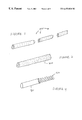
- FIG. 2 is a perspective view of a adjustable length air distribution chamber according to the invention.
- FIG. 3 is a perspective view of an inherently porous air distribution chamber according to the invention.
- FIG. 4 is a perspective, partially cutaway view of a collapsible air distribution chamber with a helical support structure according to the invention.
- FIGS. 5-10 are cross-sectional side views showing various embodiments of mounting hardware to position the air distribution chamber according to the invention.
- FIG. 11 is a flowchart of an operational sequence for warming the lower extremities of a supine person according to the invention.
- FIG. 1 shows one example embodied by the system 100 .
- a person 102 is shown in supine position on a bed 104 that has a head end 104 a and foot end 104 b .
- the person is covered by one or more blankets 106 .
- the system 100 employs a blower 110 to direct air into an elongated distribution chamber 108 .
- the chamber 108 includes many tiny exit apertures 109 .
- the chamber 108 may comprise an otherwise air impermeable material, with many tiny apertures 109 defined therein.
- the chamber 108 may comprise an air permeable substance such as a woven fabric, mesh, flexible lattice, fibrous structure, etc. The air permeable substance naturally defines many tiny apertures 109 ; additional apertures may be created to enhance air flow if desired.
- the air is conditioned by a temperature regulator 113 .
- the blower 110 and chamber 108 are coupled by a supply hose 111 .
- the chamber 109 is mounted at the foot end 104 b , so that air exiting the apertures 109 warms the person's feet 103 .
- the chamber 108 is placed under the blankets 106 , but above any mattress cover, fitted sheet, and lower bedding.
- “upper sheet” is used to collectively refer to sheets, blankets, comforters, and other layers that cover the person.
- “lower layers of bedding” refers to fitted sheets and other like materials that are placed about the mattress and therefore normally reside beneath a person in bed.
- the bed 104 may be a spring bed, air mattress, water bed, cot, hospital bed, cot, futon, or another sleeping surface.
- the mattress 105 a may be supported by various structures, such as a box spring 105 b (as illustrated), frame, floor, etc.
- the chamber 108 extends across some or all of the bed's width, and may be constructed in various fashions.
- the chamber 108 includes a length of tubular conduit, such as semi-rigid plastic, defining many apertures 109 that allow air to escape.
- the chamber may comprise sections 200 of conduit that snap screw, plug, slide or otherwise join, permitting the user to adjust the conduit's overall length according to the bed size.
- the chamber 108 comprises an air permeable material such as a length 300 of open cell foam, sponge, fibrous material, mesh, etc.
- the apertures in the chamber may be the natural spaces within the porous material, and/or additional channels, pores, or other openings may be created.
- the chamber 108 may comprise a collapsible pocket 400 that inflates whenever it receives air from the blower 110 .
- This collapsible structure may comprise cloth, plastic, or another suitably pliable material.
- the pocket 400 may optionally include a semi-rigid helix 402 , lattice, or other internal supporting structure to maintain the chamber 108 in tubular form.
- the collapsible structure may include natural air permeability and/or apertures defined therein.
- the air distribution chamber 108 is placed at the foot of the bed 104 .
- the chamber 108 may be used with or without being mounted. In most cases, however, the chamber 108 preferably secured by some mounting hardware, which is described as follows.
- the chamber may be positioned in many ways, with a suitably diverse selection of mounting hardware.
- the chamber may be located between the blankets and the lower layers of bedding, or it may be integral with the mattress, blanket or lower layers of bedding.
- FIG. 5 shows one embodiment of mounting hardware, which utilizes a first member 500 of flat, relatively rigid material, such as a plastic sheet or bar.
- This member 500 is positioned between the vertical side of the foot end of the mattress and the blankets 106 .
- the blankets 106 are tucked under the mattress 105 a and wrap around the first member 500 and chamber 108 , and then cover the person.
- This embodiment of mounting hardware also includes a second member 502 of flat, relatively rigid material, sandwiched between the bottom side of the foot end of the mattress 105 a and the box springs 105 b (or other structure beneath the mattress). As shown, the second member 502 is attached to the first member at substantially ninety degree angle, and helps secure the first member 500 and chamber 108 in position.
- FIG. 6 shows a different embodiment of mounting hardware, which positions the chamber 108 using a first member 600 only.
- the second member 502 (FIG. 5) is omitted.
- the first member 600 is held in place by the blankets 106 , which are firmly tucked in between the mattress 105 a and box spring 105 b .
- the first member 600 may be held in place by other means, such as (1) slidable insertion into a vertical pocket sewn into the lower layer of bedding 602 at the foot of the bed, (2) slidable insertion into a vertical pocket sewn into the lowermost layer of blanket 106 , or (3) fasteners attaching the member 600 to the sheet or blankets.
- Some exemplary fasteners include hook and loop (e.g., VELCRO brand), snaps, clips, adhesive, etc.
- FIG. 7 shows a different embodiment of mounting hardware.
- the chamber 108 resides in a channel 700 defined in the mattress 105 a .
- the chamber 108 is held in place by the walls of the channel 700 .
- the chamber 108 may be positioned beneath a lower layer of bedding 702 , further holding the chamber 108 in the channel 700 .
- FIG. 8 shows a different embodiment of mounting hardware.
- the mattress 105 a does not include a channel 700 (as in FIG. 7 ), but the chamber 108 is nonetheless held in position by virtue of being placed beneath the lower layer of bedding 800 .
- the chamber 108 may be further fixed in position by sewing the chamber 108 into the lower layer of bedding 800 , or a pocket sewed thereto.
- the chamber 108 may be fixed in position by sewing the chamber into a layer of the blanket 106 , or a pocket sewed thereto.
- FIG. 9 shows still another embodiment of mounting hardware.
- the chamber 108 is secured to a support structure 902 that is secured to a lower layer of bedding 904 .
- the support structure 902 serves to keep the chamber 108 fixed in position, keep the chamber's apertures (e.g., apertures 109 in FIG. 1) oriented correctly to blow air toward the patient's feet 103 , and keep the chamber 108 properly aligned with the bed.
- the support structure 902 may be implemented in many different ways, such as a molded plastic construction shaped to receive the chamber 108 and attached to the bedding 904 by hook and loop fasteners, fabric straps, adhesive strips, etc. Such a molded plastic construction may run along some or all of the chamber's length, and may even be implemented by several small brackets located at various points along the chamber's length.
- FIG. 10 shows a different embodiment of mounting hardware.
- This structure includes an air impermeable outer layer 1004 and an air permeable inner layer 1006 .
- the outer layer 1004 has an inlet 1005 , permitting air from the supply hose 111 to enter the spaces between the layers 1004 , 1006 and inflate one or more air channels 1002 .
- FIG. 10 shows two such inflatable channels 1002 in cross-sectional view. If desired, the channels 1002 may be collapsible whenever air does not flow from the supply hose 111 .
- each channel 1002 may include an internal support member such as a helix of plastic or wire.
- the inner layer 1006 is air permeable, air from the channel 1002 is exhausted through the layer 1006 into the space 1010 around the patient's feet 103 .
- the inner layer 1006 may comprise an otherwise air impermeable material with air exit apertures therein.
- the inner layer 1006 may comprise an air permeable material, such as a woven fabric, mesh, flexible lattice, fibrous structure, etc.
- the layers 1004 , 1006 may be sewn, attached, or otherwise incorporated into the blankets 106 .
- the layers 1004 , 1006 themselves may provide a lower-body blanket that lies beneath the blankets 106 or between blanket layers, with or without connection to the blankets 106 .
- blower 110 (FIG. 1 ).
- the blower 110 forces air into the air distribution chamber 108 via the supply hose 111 .
- air passes through the apertures 109 and exits the chamber 108 into the space where the person's feet 103 reside between the blankets 106 and bed 104 .
- Air from the chamber 108 remains trapped in a space created by the person's feet between the mattress and the blankets, and thereby warms the person's feet during a period of extended contact.
- the blower 110 When used with sensitive surgical or other hospital patients, the blower 110 should comprise a quiet unit.
- the blower may provide an output air flow between five and twenty-five cubic feet per minute.
- the airflow may vary widely from this range depending upon the specific design of the chamber 108 , apertures 109 , hose 111 , etc.
- the present description depicts a blower 110 that withdraws air from the atmosphere and blows this air into the hose 111 .
- ambient air may be undesirable for health, hygiene, therapy, or other reasons.
- the blower 110 may withdraw air from a prescribed vessel, filter, or other non-ambient air source.
- the blower 110 may be operated to provide filtered air, a substance other than air, or a greater concentration of a gas normally present in air (e.g., oxygen), etc.
- the blower 110 may mix different input gases, such as injecting medication into the blower's air stream, or even mixing two non-air substances.
- non-gas fluids may be utilized in small amounts, e.g. adding water vapor to increase humidity, etc.
- the system 100 also includes a temperature regulator 113 .
- the regulator 113 may be integrated into the blower 110 , or it may be separate.
- the blower/regulator may comprise a self-contained unit such as a space heater.
- the temperature regulator 113 may be configured to condition air before, during, or after the air is moved by the blower 110 .
- the regulator 113 may comprise an electrical resistance type heater.
- the temperature regulator 113 may be implemented in many different ways.
- the regulator may comprise a digital data processing apparatus that operates by executing a sequence of machine-readable instructions. Examples of this embodiment include microprocessors, personal computers, computer workstations, and the like.
- One embodiment of regulator that is suitable for this implementation uses time-based temperature regulation.
- the regulator 113 may be programmable to decrease or increase the air temperature after a selected period of time, turn the unit “on” or “off” at prescribed times, etc.
- a different embodiment of the regulator 113 uses logic circuitry instead of computer-executed instructions to perform similar temperature control functions.
- this logic may be implemented by constructing an application-specific integrated circuit (ASIC) having thousands of tiny integrated transistors.
- ASIC application-specific integrated circuit
- Such an ASIC may be implemented with CMOS, TTL, VLSI, or another suitable construction.
- Other alternatives include a digital signal processing chip (DSP), field programmable gate array (FPGA), programmable logic array (PLA), and the like.
- DSP digital signal processing chip
- FPGA field programmable gate array
- PDA programmable logic array
- the regulator 113 may even use discrete circuitry, such as resistors, capacitors, diodes, inductors, transistors, and other components configured as a feedback loop or other circuit structure to automatically control temperature.
- the temperature controller 113 employs an electronic or electro mechanical temperature controller.
- the temperature controller may sense output air temperature and adjust the electrical current provided to the heater element to maintain an operator-specified output air temperature.
- the regulator 113 may employ multiple heating elements that can be independently activated. For lower temperatures, a single element may be energized whereas for higher temperatures, multiple elements may be energized. In this case, the regulator 113 selectively activates the multiple heater elements using predetermined information such as a lookup table correlating various combinations of activated heater elements with empirically determined output temperatures likely to be produced under average room temperature conditions.
- an operator may use various means to select the desired temperature. For instance, an operator may select the desired temperature by programming the regulator 113 (which subsequently operates automatically), turning a dial, punching a keypad, adjusting a rheostat, sliding a lever, etc.
- the temperature of the blower's output air is important for various reasons. As mentioned above, the present inventors recognize that persons with diabetes and other vascular diseases frequently lose sensation in their feet and legs. These people are prone to foot injuries because they cannot feel blisters and other injuries forming, and therefore fail to take any preventive action. Relatedly, these people are prone to burn injuries because they cannot feel the temperature and pain of thermal damage to the skin. Thermal damage to inadequately perfused skin can occur at temperatures as low as 40° Celsius. By most standards, 40° Celsius is merely warm, not hot, yet in the case of inadequate blood flow to the skin, this temperature can cause a thermal injury or burn.
- the temperature regulator 113 may warm the air around the person's feet to a temperature that is greater than room temperature and less than 40° Celsius.
- the regulator 113 may warm air to a temperature corresponding the upper limit of normothermia, such as about 38° Celsius. Limiting air temperature to the upper limit of normothermia is especially desirable to avoid skin damage in people that have limited sensation in their lower extremities due to diabetes, vascular disease, or another condition affecting circulation.
- FIG. 11 shows a sequence 1100 to illustrate one example of this aspect of the invention.
- the example of FIG. 11 is described in the context of the system 100 described above.
- step 1102 medical staff use mounting hardware as described above to affix the air distribution chamber 108 at the foot of the bed 104 . If desired, the chamber 108 may be laid at the foot of the bed without any attachment. Step 1104 also includes the additional steps of attaching the hose 111 to the chamber 108 and blower 110 , applying electrical power to the blower 110 , selecting the desired output temperature, entering any additional programming the blower 110 if applicable, etc.
- step 1106 the person 102 gets into bed. If desired, the order of steps 1104 , 1106 may be reversed or even combined.
- step 1108 the temperature regulator 113 begins to regulate the temperature of the air or other air being supplied by the blower 110 .
- the regulator 113 provides output air temperature near the upper limit of normothermia, or about 37° Celsius. For people with normal pain sensation in the feet, the regulator 113 may even produce hyperthermic temperatures.
- the blower 110 starts to direct air (or other air) to the chamber 108 in step 1110 . Pressure from the blower 110 forces air out the apertures 109 in the chamber 108 .
- the person's feet 103 protrude and create a space between the blanket 106 and bed 104 . Air emerging from the nearby apertures 109 warms this space between the blanket 106 and bed 104 , thereby surrounding the feet with warm air.
- step 1112 determines whether an operator has issued an “off” command, such as by turning off the regulator 113 , blower 110 , or a master control. If not, air flow and temperature regulation continue in step 1114 . Otherwise, when the “off” command is detected, the routine 1100 ends in step 1116 .
Abstract
Description
Claims (4)
Priority Applications (4)
| Application Number | Priority Date | Filing Date | Title |
|---|---|---|---|
| US09/439,548 US6473920B2 (en) | 1999-11-12 | 1999-11-12 | System for warming lower extremities of supine persons |
| AU39684/01A AU3968401A (en) | 1999-11-12 | 2000-11-03 | System for warming lower extremities of supine persons |
| PCT/US2000/041882 WO2001035879A2 (en) | 1999-11-12 | 2000-11-03 | System for warming lower extremities of supine persons |
| US10/198,842 US7120951B2 (en) | 1999-11-12 | 2002-07-19 | System for warming lower extremities of supine persons |
Applications Claiming Priority (1)
| Application Number | Priority Date | Filing Date | Title |
|---|---|---|---|
| US09/439,548 US6473920B2 (en) | 1999-11-12 | 1999-11-12 | System for warming lower extremities of supine persons |
Related Child Applications (1)
| Application Number | Title | Priority Date | Filing Date |
|---|---|---|---|
| US10/198,842 Continuation US7120951B2 (en) | 1999-11-12 | 2002-07-19 | System for warming lower extremities of supine persons |
Publications (2)
| Publication Number | Publication Date |
|---|---|
| US20020138901A1 US20020138901A1 (en) | 2002-10-03 |
| US6473920B2 true US6473920B2 (en) | 2002-11-05 |
Family
ID=23745151
Family Applications (2)
| Application Number | Title | Priority Date | Filing Date |
|---|---|---|---|
| US09/439,548 Expired - Fee Related US6473920B2 (en) | 1999-11-12 | 1999-11-12 | System for warming lower extremities of supine persons |
| US10/198,842 Expired - Fee Related US7120951B2 (en) | 1999-11-12 | 2002-07-19 | System for warming lower extremities of supine persons |
Family Applications After (1)
| Application Number | Title | Priority Date | Filing Date |
|---|---|---|---|
| US10/198,842 Expired - Fee Related US7120951B2 (en) | 1999-11-12 | 2002-07-19 | System for warming lower extremities of supine persons |
Country Status (3)
| Country | Link |
|---|---|
| US (2) | US6473920B2 (en) |
| AU (1) | AU3968401A (en) |
| WO (1) | WO2001035879A2 (en) |
Cited By (32)
| Publication number | Priority date | Publication date | Assignee | Title |
|---|---|---|---|---|
| US20030047556A1 (en) * | 2001-09-11 | 2003-03-13 | Horey Leonard I. | Warming blanket having remote safety circuit |
| US6553935B1 (en) * | 2002-06-01 | 2003-04-29 | Tim Penner | Pet air bed |
| WO2003037141A2 (en) * | 1999-12-13 | 2003-05-08 | Mark Flores | Air-flow containment and distribution assembly |
| US6711767B2 (en) | 2002-01-30 | 2004-03-30 | Thomas Klamm | Apparatus for warming a bed |
| US20040064342A1 (en) * | 2002-09-30 | 2004-04-01 | Browne David W. | Health care protocols |
| US20040214148A1 (en) * | 2003-04-22 | 2004-10-28 | Salvino Robert J. | Updating health care protocols |
| US20040249419A1 (en) * | 2003-04-02 | 2004-12-09 | Chapman Fred William | Defibrillators customized for anticipated patients |
| US20050015115A1 (en) * | 2003-07-16 | 2005-01-20 | Sullivan Joseph L. | First aid system |
| US20050278863A1 (en) * | 2004-06-22 | 2005-12-22 | Riverpark Incorporated | Comfort product |
| US20060079170A1 (en) * | 2003-04-08 | 2006-04-13 | Halo Innovations, Inc. | Systems for delivering conditioned air to personal breathing zones |
| US20060085911A1 (en) * | 2004-10-21 | 2006-04-27 | Tompkins Kurt W | Portable ventilation system |
| US7036575B1 (en) * | 2002-03-19 | 2006-05-02 | Rodney James W | Forced air bed warmer/cooler |
| US7087075B2 (en) * | 2002-09-30 | 2006-08-08 | Medtronic Emergency Response Systems, Inc. | Feedback system for rapid induction of mild hypothermia |
| US20060198617A1 (en) * | 2005-03-04 | 2006-09-07 | Shlomo Sirkis | Portable bed warmer |
| US7179279B2 (en) * | 2002-09-30 | 2007-02-20 | Medtronic Physio Control Corp. | Rapid induction of mild hypothermia |
| US7509998B1 (en) * | 2002-03-19 | 2009-03-31 | James W Rodney | Forced air aromatic bed warmer/cooler |
| US20090143844A1 (en) * | 2007-11-29 | 2009-06-04 | Gaymar Industries, Inc. | Hose management for convective devices |
| US20090233540A1 (en) * | 2008-03-17 | 2009-09-17 | Valentino Joseph A | Systems and methods for ventilation of a surgical table |
| US7631377B1 (en) | 2008-07-09 | 2009-12-15 | Sanford Alonzo W | Bed ventilator unit |
| US20100071130A1 (en) * | 2008-09-23 | 2010-03-25 | Jacobo Frias | Inflatable temperature control system |
| US7707840B1 (en) | 2009-06-10 | 2010-05-04 | Flores Mark A | Portable air-conditioning unit |
| US20110247134A1 (en) * | 2010-04-09 | 2011-10-13 | Howell Charles A | Siderail accessory module |
| US8261388B1 (en) | 2009-05-16 | 2012-09-11 | Gill Zora S | Human cushion apparatus |
| US20150121619A1 (en) * | 2013-11-06 | 2015-05-07 | Mark Aramli | Forced Air Apparatus for Conditioning a Volume of Air |
| US20150121620A1 (en) * | 2013-11-06 | 2015-05-07 | Mark Aramli | Bedding climate control apparatus with forced airflow for heating and ventilating |
| US20170340128A1 (en) * | 2013-11-06 | 2017-11-30 | Mark Darius Aramli | Bedding climate control apparatus and method to operate thereof |
| US9949570B1 (en) | 2016-12-19 | 2018-04-24 | James C. Young | Bed warmer system |
| US20180310716A1 (en) * | 2017-04-27 | 2018-11-01 | UHV Technologies, Inc. | Air conditioning system for a reduced space area of a room |
| US20190223614A1 (en) * | 2013-11-06 | 2019-07-25 | Mark Darius Aramli | Bedding climate control apparatus and method to operate thereof to tent up bedding in a quiet manner because of noise dampening and component oversizing |
| US20190223616A1 (en) * | 2013-11-06 | 2019-07-25 | Mark Darius Aramli | Bedding climate control apparatus and method to operate thereof that compensates for backpressure and ambient temperature |
| US20200404987A1 (en) * | 2017-03-30 | 2020-12-31 | Max Betkowski | Tri-modal localized heating garment |
| US20230371703A1 (en) * | 2013-11-06 | 2023-11-23 | Bedjet Llc | Bedding climate control apparatus and method to operate thereof that creates a heat transfer effect |
Families Citing this family (22)
| Publication number | Priority date | Publication date | Assignee | Title |
|---|---|---|---|---|
| ATE550067T1 (en) * | 2003-07-22 | 2012-04-15 | Kci Licensing Inc | NEGATIVE PRESSURE WOUND TREATMENT COMPRESS |
| US8182521B2 (en) | 2003-09-24 | 2012-05-22 | Dynatherm Medical Inc. | Methods and apparatus for increasing blood circulation |
| WO2005030101A1 (en) * | 2003-09-24 | 2005-04-07 | Dynatherm Medical, Inc. | Methods and apparatus for adjusting body core temperature |
| US7470280B2 (en) * | 2005-02-11 | 2008-12-30 | Arizant Healthcare Inc. | Clinical garment for comfort warming and prewarming |
| KR100647138B1 (en) | 2005-04-01 | 2006-11-23 | 윤장호 | The mat |
| FR2888098B1 (en) * | 2005-07-06 | 2011-04-08 | Christine Nau | TEMPERATURE PACKING DEVICE FOR LITERARY AND SLEEPING EQUIPMENT |
| US20070257018A1 (en) * | 2006-05-03 | 2007-11-08 | Huang Henry D | Programmable Thermally Controlled Electric Heating Mattress |
| US9308148B2 (en) | 2006-12-04 | 2016-04-12 | Thermatx, Inc. | Methods and apparatus for adjusting blood circulation |
| US8603150B2 (en) | 2006-12-04 | 2013-12-10 | Carefusion 2200, Inc. | Methods and apparatus for adjusting blood circulation |
| KR20090110934A (en) | 2007-02-09 | 2009-10-23 | 케이씨아이 라이센싱 인코포레이티드 | A breathable interface system for trofical reduced presuure |
| CH703806B1 (en) | 2007-03-14 | 2012-03-30 | Vincent De Oliveira | hanging bed. |
| US8377017B2 (en) | 2008-01-03 | 2013-02-19 | Kci Licensing, Inc. | Low-profile reduced pressure treatment system |
| CH701932B1 (en) * | 2008-01-03 | 2011-04-15 | Clemens Dr Med Gutknecht | Patient bed with monitoring and therapy device. |
| US8158844B2 (en) | 2008-10-08 | 2012-04-17 | Kci Licensing, Inc. | Limited-access, reduced-pressure systems and methods |
| KR20120123408A (en) | 2010-01-08 | 2012-11-08 | 다이나썸 메디칼, 인코포레이티드 | Methods and apparatus for enhancing vascular access in an appendage to enhance therapeutic and interventional procedures |
| US9138064B2 (en) | 2013-01-18 | 2015-09-22 | Fxi, Inc. | Mattress with combination of pressure redistribution and internal air flow guides |
| US9392875B2 (en) * | 2013-01-18 | 2016-07-19 | Fxi, Inc. | Body support system with combination of pressure redistribution and internal air flow guide(s) for withdrawing heat and moisture away from body reclining on support surface of body support system |
| GB2526320B (en) * | 2014-05-21 | 2016-05-11 | Jeremy Worth Matthew | Apparatus for effecting temperature change in a bed |
| WO2016030774A1 (en) * | 2014-08-23 | 2016-03-03 | Padmini Vna Mechatronics Pvt. Ltd. | Device for a climate controlled ambience and method thereof |
| US10827846B2 (en) | 2016-10-28 | 2020-11-10 | Sleep Number Corporation | Bed with foot warming system |
| US20180243126A1 (en) * | 2017-02-28 | 2018-08-30 | Simple Solutions Inc. | Portable blower for supplying ventilation to wounds |
| US11140987B2 (en) | 2019-02-14 | 2021-10-12 | Deer Solutions LLC | Athletic chair with adjustable heating and height |
Citations (7)
| Publication number | Priority date | Publication date | Assignee | Title |
|---|---|---|---|---|
| US2640205A (en) | 1950-05-19 | 1953-06-02 | Alice H Simpson | Foot support and warmer for beds |
| US3101488A (en) * | 1961-07-10 | 1963-08-27 | Peebles David Meade | Air purifying and ventilating means for beds |
| US3230556A (en) * | 1962-05-07 | 1966-01-25 | Shippee Wiusor | Construction for maintaining a controlled temperature environment in a bed |
| US3713182A (en) * | 1971-05-26 | 1973-01-30 | Neal H Mc | Bedclothes elevator and bed warmer |
| US4006604A (en) * | 1976-01-23 | 1977-02-08 | Lawrence Peska Associates, Inc. | Air conditioned pillow |
| US5165400A (en) | 1991-03-04 | 1992-11-24 | Cincinnati Sub-Zero Products, Inc. | Convective hyperthermia article |
| US5941907A (en) | 1997-06-02 | 1999-08-24 | Augustine Medical, Inc. | Surgical barrier device incorporating an inflatable thermal blanket with a surgical drape to provide thermal control and surgical access |
Family Cites Families (8)
| Publication number | Priority date | Publication date | Assignee | Title |
|---|---|---|---|---|
| FR851343A (en) | 1940-01-06 | |||
| GB851343A (en) * | 1958-07-02 | 1960-10-12 | Jacques Minot | Improvements in and relating to bed-clothes supports and bed warmers |
| US3444922A (en) * | 1966-12-06 | 1969-05-20 | Edward H Dingman | Apparatus for passing flowing air about a bed occupant at selective temperatures |
| GB1334935A (en) * | 1971-03-02 | 1973-10-24 | Howorth Air Conditioning Ltd | Mattress |
| JPS6053743A (en) * | 1983-09-02 | 1985-03-27 | Sanyo Electric Co Ltd | Warm air circulating type foot warmer |
| US5305483A (en) * | 1993-03-08 | 1994-04-26 | Watkins Charles E | Infant body support and providing air flow for breathing |
| US5473783A (en) * | 1994-04-04 | 1995-12-12 | Allen; Randall W. | Air percolating pad |
| US5887304A (en) * | 1997-07-10 | 1999-03-30 | Von Der Heyde; Christian P. | Apparatus and method for preventing sudden infant death syndrome |
-
1999
- 1999-11-12 US US09/439,548 patent/US6473920B2/en not_active Expired - Fee Related
-
2000
- 2000-11-03 WO PCT/US2000/041882 patent/WO2001035879A2/en active Application Filing
- 2000-11-03 AU AU39684/01A patent/AU3968401A/en not_active Abandoned
-
2002
- 2002-07-19 US US10/198,842 patent/US7120951B2/en not_active Expired - Fee Related
Patent Citations (7)
| Publication number | Priority date | Publication date | Assignee | Title |
|---|---|---|---|---|
| US2640205A (en) | 1950-05-19 | 1953-06-02 | Alice H Simpson | Foot support and warmer for beds |
| US3101488A (en) * | 1961-07-10 | 1963-08-27 | Peebles David Meade | Air purifying and ventilating means for beds |
| US3230556A (en) * | 1962-05-07 | 1966-01-25 | Shippee Wiusor | Construction for maintaining a controlled temperature environment in a bed |
| US3713182A (en) * | 1971-05-26 | 1973-01-30 | Neal H Mc | Bedclothes elevator and bed warmer |
| US4006604A (en) * | 1976-01-23 | 1977-02-08 | Lawrence Peska Associates, Inc. | Air conditioned pillow |
| US5165400A (en) | 1991-03-04 | 1992-11-24 | Cincinnati Sub-Zero Products, Inc. | Convective hyperthermia article |
| US5941907A (en) | 1997-06-02 | 1999-08-24 | Augustine Medical, Inc. | Surgical barrier device incorporating an inflatable thermal blanket with a surgical drape to provide thermal control and surgical access |
Non-Patent Citations (1)
| Title |
|---|
| Written Opinion from PCT/US00/41882. |
Cited By (52)
| Publication number | Priority date | Publication date | Assignee | Title |
|---|---|---|---|---|
| WO2003037141A2 (en) * | 1999-12-13 | 2003-05-08 | Mark Flores | Air-flow containment and distribution assembly |
| WO2003037141A3 (en) * | 1999-12-13 | 2003-07-10 | Mark Flores | Air-flow containment and distribution assembly |
| US6730887B2 (en) * | 2001-09-11 | 2004-05-04 | Sunbeam Products, Inc. | Warming blanket having remote safety circuit |
| US20030047556A1 (en) * | 2001-09-11 | 2003-03-13 | Horey Leonard I. | Warming blanket having remote safety circuit |
| US6711767B2 (en) | 2002-01-30 | 2004-03-30 | Thomas Klamm | Apparatus for warming a bed |
| US7036575B1 (en) * | 2002-03-19 | 2006-05-02 | Rodney James W | Forced air bed warmer/cooler |
| US7509998B1 (en) * | 2002-03-19 | 2009-03-31 | James W Rodney | Forced air aromatic bed warmer/cooler |
| US6553935B1 (en) * | 2002-06-01 | 2003-04-29 | Tim Penner | Pet air bed |
| US20040064342A1 (en) * | 2002-09-30 | 2004-04-01 | Browne David W. | Health care protocols |
| US7179279B2 (en) * | 2002-09-30 | 2007-02-20 | Medtronic Physio Control Corp. | Rapid induction of mild hypothermia |
| US7087075B2 (en) * | 2002-09-30 | 2006-08-08 | Medtronic Emergency Response Systems, Inc. | Feedback system for rapid induction of mild hypothermia |
| US20100318143A1 (en) * | 2003-04-02 | 2010-12-16 | Physio-Control, Inc. | Defibrillators customized for anticipated patients |
| US8090439B2 (en) | 2003-04-02 | 2012-01-03 | Physio Control, Inc. | Defibrillators customized for anticipated patients |
| US8090440B2 (en) | 2003-04-02 | 2012-01-03 | Physio Control, Inc. | Defibrillators customized for anticipated patients |
| US20100318145A1 (en) * | 2003-04-02 | 2010-12-16 | Physio-Control, Inc. | Defibrillators customized for anticipated patients |
| US8090441B2 (en) | 2003-04-02 | 2012-01-03 | Physio Control, Inc. | Defibrillators customized for anticipated patients |
| US20040249419A1 (en) * | 2003-04-02 | 2004-12-09 | Chapman Fred William | Defibrillators customized for anticipated patients |
| US20100318144A1 (en) * | 2003-04-02 | 2010-12-16 | Physio-Control, Inc. | Defibrillators customized for anticipated patients |
| US7805190B2 (en) | 2003-04-02 | 2010-09-28 | Physio-Control, Inc. | Defibrillators customized for anticipated patients |
| US20060079170A1 (en) * | 2003-04-08 | 2006-04-13 | Halo Innovations, Inc. | Systems for delivering conditioned air to personal breathing zones |
| US20040214148A1 (en) * | 2003-04-22 | 2004-10-28 | Salvino Robert J. | Updating health care protocols |
| US20050015115A1 (en) * | 2003-07-16 | 2005-01-20 | Sullivan Joseph L. | First aid system |
| US20100087883A1 (en) * | 2003-07-16 | 2010-04-08 | Medtronic Physio-Control Corp. | Interactive first aid information system |
| US7623915B2 (en) | 2003-07-16 | 2009-11-24 | Medtronic Physio-Control Corp. | Interactive first aid information system |
| US20100297594A1 (en) * | 2003-07-16 | 2010-11-25 | Physio-Control, Inc. | Interactive first aid information system |
| US20050278863A1 (en) * | 2004-06-22 | 2005-12-22 | Riverpark Incorporated | Comfort product |
| US20060085911A1 (en) * | 2004-10-21 | 2006-04-27 | Tompkins Kurt W | Portable ventilation system |
| US20060198617A1 (en) * | 2005-03-04 | 2006-09-07 | Shlomo Sirkis | Portable bed warmer |
| US20090143844A1 (en) * | 2007-11-29 | 2009-06-04 | Gaymar Industries, Inc. | Hose management for convective devices |
| US20090233540A1 (en) * | 2008-03-17 | 2009-09-17 | Valentino Joseph A | Systems and methods for ventilation of a surgical table |
| US7631377B1 (en) | 2008-07-09 | 2009-12-15 | Sanford Alonzo W | Bed ventilator unit |
| US20100071130A1 (en) * | 2008-09-23 | 2010-03-25 | Jacobo Frias | Inflatable temperature control system |
| US8151391B2 (en) | 2008-09-23 | 2012-04-10 | Jacobo Frias | Inflatable temperature control system |
| US8261388B1 (en) | 2009-05-16 | 2012-09-11 | Gill Zora S | Human cushion apparatus |
| US7707840B1 (en) | 2009-06-10 | 2010-05-04 | Flores Mark A | Portable air-conditioning unit |
| US20110247134A1 (en) * | 2010-04-09 | 2011-10-13 | Howell Charles A | Siderail accessory module |
| US20190223614A1 (en) * | 2013-11-06 | 2019-07-25 | Mark Darius Aramli | Bedding climate control apparatus and method to operate thereof to tent up bedding in a quiet manner because of noise dampening and component oversizing |
| US10660451B2 (en) * | 2013-11-06 | 2020-05-26 | Bedjet Llc | Bedding climate control apparatus and method to operate thereof that compensates for backpressure and ambient temperature |
| US9782016B2 (en) * | 2013-11-06 | 2017-10-10 | Mark Aramli | Bedding climate control apparatus with forced airflow for heating and ventilating |
| US20170340128A1 (en) * | 2013-11-06 | 2017-11-30 | Mark Darius Aramli | Bedding climate control apparatus and method to operate thereof |
| US11944204B2 (en) * | 2013-11-06 | 2024-04-02 | Bedjet Llc | Bedding climate control apparatus and method to operate thereof that creates a heat transfer effect |
| US20230371703A1 (en) * | 2013-11-06 | 2023-11-23 | Bedjet Llc | Bedding climate control apparatus and method to operate thereof that creates a heat transfer effect |
| US20150121619A1 (en) * | 2013-11-06 | 2015-05-07 | Mark Aramli | Forced Air Apparatus for Conditioning a Volume of Air |
| US20190223616A1 (en) * | 2013-11-06 | 2019-07-25 | Mark Darius Aramli | Bedding climate control apparatus and method to operate thereof that compensates for backpressure and ambient temperature |
| US10524581B2 (en) * | 2013-11-06 | 2020-01-07 | Bedjet Llc | Bedding climate control apparatus and method to operate thereof |
| US10582776B2 (en) * | 2013-11-06 | 2020-03-10 | Bedjet Llc | Bedding climate control apparatus and method to operate thereof to tent up bedding in a quiet manner because of noise dampening and component oversizing |
| US20150121620A1 (en) * | 2013-11-06 | 2015-05-07 | Mark Aramli | Bedding climate control apparatus with forced airflow for heating and ventilating |
| US11700951B2 (en) * | 2013-11-06 | 2023-07-18 | Bedjet Llc | Bedding climate control apparatus and method to operate thereof with a programmable application from a wireless network |
| US20210196051A1 (en) * | 2013-11-06 | 2021-07-01 | Bedjet Llc | Bedding climate control apparatus and method to operate thereof with a programmable application from a wireless network |
| US9949570B1 (en) | 2016-12-19 | 2018-04-24 | James C. Young | Bed warmer system |
| US20200404987A1 (en) * | 2017-03-30 | 2020-12-31 | Max Betkowski | Tri-modal localized heating garment |
| US20180310716A1 (en) * | 2017-04-27 | 2018-11-01 | UHV Technologies, Inc. | Air conditioning system for a reduced space area of a room |
Also Published As
| Publication number | Publication date |
|---|---|
| US20020138901A1 (en) | 2002-10-03 |
| US7120951B2 (en) | 2006-10-17 |
| AU3968401A (en) | 2001-05-30 |
| WO2001035879A2 (en) | 2001-05-25 |
| US20020178499A1 (en) | 2002-12-05 |
| WO2001035879A3 (en) | 2002-02-14 |
Similar Documents
| Publication | Publication Date | Title |
|---|---|---|
| US6473920B2 (en) | System for warming lower extremities of supine persons | |
| US6511501B1 (en) | Inflatable thermal pad with drainage | |
| EP2713967B1 (en) | Temperature-controlled multi-zone mattress-style support | |
| US7066949B2 (en) | Closed-loop heat therapy blanket | |
| JP2007175476A (en) | Temperature-adjustable mat | |
| US5304213A (en) | Hyper-hypothermia blanket with filtration properties | |
| US7014431B2 (en) | Forced air warming unit | |
| US4631767A (en) | Air flotation mattress | |
| US20140007353A1 (en) | Patient turner | |
| US20030057289A1 (en) | Temperature control device for sleeping | |
| US20110185508A1 (en) | Prevention and Treatment of Pressure Sores Using a Sheet with an Integrated Inflatable Component | |
| US20110010855A1 (en) | Therapy and Low Air Loss Universal Coverlet | |
| JP2002519100A (en) | Patient support equipment to be heated | |
| WO2001037773A1 (en) | A ventilation apparatus | |
| JP2008289654A (en) | Temperature-regulating mattress | |
| US20060198617A1 (en) | Portable bed warmer | |
| JP2010075377A (en) | Temperature-regulating mattress | |
| US20140259400A1 (en) | Patient support with microclimate management system | |
| US20180085054A1 (en) | Sleep surface system and method thereof | |
| US10842285B1 (en) | Leg pillow | |
| US5813407A (en) | Blanket with permeable window | |
| CN209712292U (en) | Multi-temperature zone health mattress | |
| WO2005007054A1 (en) | System and method for medical equipment | |
| CN214018234U (en) | Temperature-adjustable ventilation mattress convenient for turning over | |
| CA1252920A (en) | Air flotation mattress |
Legal Events
| Date | Code | Title | Description |
|---|---|---|---|
| AS | Assignment |
Owner name: AUGUSTINE MEDICAL, INC., MINNESOTA Free format text: ASSIGNMENT OF ASSIGNORS INTEREST;ASSIGNORS:AUGUSTINE, SCOTT D.;AUGUSTINE, SUSAN DYKINS;AUGUSTINE, GARRETT JESSE;AND OTHERS;REEL/FRAME:010412/0130 Effective date: 19991109 |
|
| AS | Assignment |
Owner name: ARIZANT HEALTHCARE INC., MINNESOTA Free format text: ASSIGNMENT OF ASSIGNORS INTEREST;ASSIGNOR:AUGUSTINE MEDICAL, INC.;REEL/FRAME:013804/0785 Effective date: 20030217 |
|
| AS | Assignment |
Owner name: MERRILL LYNCH CAPITAL, A DIVISION OF MERRILL LYNCH Free format text: SECURITY INTEREST;ASSIGNOR:ARIZANT HEALTHCARE INC.;REEL/FRAME:015629/0084 Effective date: 20040730 |
|
| FPAY | Fee payment |
Year of fee payment: 4 |
|
| AS | Assignment |
Owner name: GENERAL ELECTRIC CAPITAL CORPORATION,AS ADMINISTRA Free format text: SECURITY AGREEMENT;ASSIGNOR:ARIZANT HEALTHCARE INC.;REEL/FRAME:022813/0114 Effective date: 20090611 |
|
| AS | Assignment |
Owner name: ARIZANT HEALTHCARE INC., MINNESOTA Free format text: RELEASE BY SECURED PARTY;ASSIGNOR:GE BUSINESS FINANCIAL SERVICES INC. (F/K/A MERRILL LYNCH BUSINESS FINANCIAL SERVICES INC.), AS ADMINISTRATIVE AGENT;REEL/FRAME:022813/0325 Effective date: 20090611 |
|
| FPAY | Fee payment |
Year of fee payment: 8 |
|
| AS | Assignment |
Owner name: GENERAL ELECTRIC CAPITAL CORPORATION, MARYLAND Free format text: ASSIGNMENT OF ASSIGNORS INTEREST;ASSIGNOR:ARIZANT HEALTHCARE INC.;REEL/FRAME:025137/0066 Effective date: 20101013 |
|
| AS | Assignment |
Owner name: ARIZANT HEALTHCARE INC., MINNESOTA Free format text: CORRECTIVE ASSIGNMENT TO CORRECT THE NATURE OF THE CONVEYANCE AS A RELEASE BY SECURED PARTY, AND THE IDENTITY OF THE ASSIGNOR AND ASSIGNEE PREVIOUSLY RECORDED ON REEL 025137 FRAME 0066. ASSIGNOR(S) HEREBY CONFIRMS THE RELEASE OF SECURITY INTEREST IN ALL OF GRANTOR'S RIGHT, TITLE AND INTEREST IN PATENT RIGHTS;ASSIGNOR:GENERAL ELECTRIC CAPITAL CORPORATION, AS ADMINISTRATIVE AGENT;REEL/FRAME:025444/0901 Effective date: 20101013 |
|
| REMI | Maintenance fee reminder mailed | ||
| LAPS | Lapse for failure to pay maintenance fees | ||
| STCH | Information on status: patent discontinuation |
Free format text: PATENT EXPIRED DUE TO NONPAYMENT OF MAINTENANCE FEES UNDER 37 CFR 1.362 |
|
| FP | Lapsed due to failure to pay maintenance fee |
Effective date: 20141105 |