EP2945240B1 - Dispositif de répartition de l'alimentation, dispositif de surveillance de conducteur de mise à la terre et procédé - Google Patents
Dispositif de répartition de l'alimentation, dispositif de surveillance de conducteur de mise à la terre et procédé Download PDFInfo
- Publication number
- EP2945240B1 EP2945240B1 EP15167563.4A EP15167563A EP2945240B1 EP 2945240 B1 EP2945240 B1 EP 2945240B1 EP 15167563 A EP15167563 A EP 15167563A EP 2945240 B1 EP2945240 B1 EP 2945240B1
- Authority
- EP
- European Patent Office
- Prior art keywords
- protective conductor
- potential
- arrangement
- comparator
- voltage
- Prior art date
- Legal status (The legal status is an assumption and is not a legal conclusion. Google has not performed a legal analysis and makes no representation as to the accuracy of the status listed.)
- Active
Links
- 239000004020 conductor Substances 0.000 title claims description 201
- 238000012806 monitoring device Methods 0.000 title claims description 45
- 238000000034 method Methods 0.000 title claims description 10
- 230000001681 protective effect Effects 0.000 claims description 161
- 238000005259 measurement Methods 0.000 claims description 44
- 238000012544 monitoring process Methods 0.000 claims description 34
- 238000001514 detection method Methods 0.000 claims description 31
- 239000003990 capacitor Substances 0.000 claims description 21
- 230000007935 neutral effect Effects 0.000 claims description 20
- 238000010276 construction Methods 0.000 claims description 7
- 230000003287 optical effect Effects 0.000 claims description 5
- 230000001419 dependent effect Effects 0.000 claims description 2
- 230000006870 function Effects 0.000 description 6
- 238000012360 testing method Methods 0.000 description 6
- 238000010586 diagram Methods 0.000 description 5
- 101000611618 Homo sapiens Photoreceptor disk component PRCD Proteins 0.000 description 4
- 102100040826 Photoreceptor disk component PRCD Human genes 0.000 description 4
- 238000005516 engineering process Methods 0.000 description 4
- 239000004065 semiconductor Substances 0.000 description 4
- 230000008569 process Effects 0.000 description 3
- 238000012546 transfer Methods 0.000 description 3
- 230000008901 benefit Effects 0.000 description 2
- 230000000903 blocking effect Effects 0.000 description 2
- 230000008878 coupling Effects 0.000 description 2
- 238000010168 coupling process Methods 0.000 description 2
- 238000005859 coupling reaction Methods 0.000 description 2
- 230000002950 deficient Effects 0.000 description 2
- 230000006866 deterioration Effects 0.000 description 2
- 238000009434 installation Methods 0.000 description 2
- 230000000737 periodic effect Effects 0.000 description 2
- 230000035945 sensitivity Effects 0.000 description 2
- 230000000007 visual effect Effects 0.000 description 2
- 241001295925 Gegenes Species 0.000 description 1
- 230000003321 amplification Effects 0.000 description 1
- 238000013459 approach Methods 0.000 description 1
- 230000006399 behavior Effects 0.000 description 1
- 230000007797 corrosion Effects 0.000 description 1
- 238000005260 corrosion Methods 0.000 description 1
- 238000011161 development Methods 0.000 description 1
- 238000007599 discharging Methods 0.000 description 1
- 230000000694 effects Effects 0.000 description 1
- 238000011156 evaluation Methods 0.000 description 1
- 238000007667 floating Methods 0.000 description 1
- 238000009499 grossing Methods 0.000 description 1
- 230000003993 interaction Effects 0.000 description 1
- 230000007774 longterm Effects 0.000 description 1
- 239000002184 metal Substances 0.000 description 1
- 238000003199 nucleic acid amplification method Methods 0.000 description 1
- 230000004044 response Effects 0.000 description 1
- 238000005070 sampling Methods 0.000 description 1
- 238000011896 sensitive detection Methods 0.000 description 1
- 238000000926 separation method Methods 0.000 description 1
- 210000002023 somite Anatomy 0.000 description 1
- 238000011144 upstream manufacturing Methods 0.000 description 1
- 238000005406 washing Methods 0.000 description 1
Images


Classifications
-
- H—ELECTRICITY
- H02—GENERATION; CONVERSION OR DISTRIBUTION OF ELECTRIC POWER
- H02H—EMERGENCY PROTECTIVE CIRCUIT ARRANGEMENTS
- H02H5/00—Emergency protective circuit arrangements for automatic disconnection directly responsive to an undesired change from normal non-electric working conditions with or without subsequent reconnection
- H02H5/10—Emergency protective circuit arrangements for automatic disconnection directly responsive to an undesired change from normal non-electric working conditions with or without subsequent reconnection responsive to mechanical injury, e.g. rupture of line, breakage of earth connection
- H02H5/105—Emergency protective circuit arrangements for automatic disconnection directly responsive to an undesired change from normal non-electric working conditions with or without subsequent reconnection responsive to mechanical injury, e.g. rupture of line, breakage of earth connection responsive to deterioration or interruption of earth connection
-
- G—PHYSICS
- G01—MEASURING; TESTING
- G01R—MEASURING ELECTRIC VARIABLES; MEASURING MAGNETIC VARIABLES
- G01R31/00—Arrangements for testing electric properties; Arrangements for locating electric faults; Arrangements for electrical testing characterised by what is being tested not provided for elsewhere
- G01R31/50—Testing of electric apparatus, lines, cables or components for short-circuits, continuity, leakage current or incorrect line connections
- G01R31/52—Testing for short-circuits, leakage current or ground faults
-
- G—PHYSICS
- G01—MEASURING; TESTING
- G01R—MEASURING ELECTRIC VARIABLES; MEASURING MAGNETIC VARIABLES
- G01R31/00—Arrangements for testing electric properties; Arrangements for locating electric faults; Arrangements for electrical testing characterised by what is being tested not provided for elsewhere
- G01R31/50—Testing of electric apparatus, lines, cables or components for short-circuits, continuity, leakage current or incorrect line connections
- G01R31/58—Testing of lines, cables or conductors
-
- H—ELECTRICITY
- H02—GENERATION; CONVERSION OR DISTRIBUTION OF ELECTRIC POWER
- H02H—EMERGENCY PROTECTIVE CIRCUIT ARRANGEMENTS
- H02H3/00—Emergency protective circuit arrangements for automatic disconnection directly responsive to an undesired change from normal electric working condition with or without subsequent reconnection ; integrated protection
- H02H3/14—Emergency protective circuit arrangements for automatic disconnection directly responsive to an undesired change from normal electric working condition with or without subsequent reconnection ; integrated protection responsive to occurrence of voltage on parts normally at earth potential
Definitions
- the invention relates to a power distribution device which is designed to be stationary or changeable, in particular a socket, socket strip, plug adapter, cable reel, construction power distributor, connecting line or extension line, and which serves to provide a mains voltage to one or more electrical consumers, provided by a protective earth conductor is supplied to the electrical line, with a protective conductor monitoring device for detecting a protective conductor fault on the electrical line, the protective conductor monitoring device comprising a first connection point which is or can be electrically connected to the protective conductor.
- the invention further relates to a protective conductor monitoring method for detecting a protective conductor fault on an electrical line equipped with a protective conductor.
- a power distribution device is generally to be understood as a device which is used to supply mains voltage to an electrical consumer and for which it can or is connected to at least one phase conductor, a neutral conductor and a protective conductor of an electrical line, such as a mains line of a distributor , Such a power distribution device also serves to establish an electrical contact between a protective conductor connection of an electrical consumer and the protective conductor to produce an electrical line.
- a power distribution device can be designed to be stationary; ie a power distribution device can be designed to be permanently connected to a building installation during operation.
- a power distribution device can be designed as a socket or socket installation or as a device in a DIN rail construction.
- a power distribution device can also be designed to be portable and, for example, have a plug, so that it can be used at different locations as required and can be detachably connected to connections of different electrical lines.
- a power distribution device can be designed as a power strip, plug adapter, cable reel, construction power distributor, connection line or extension line.
- a power line extension with a test unit which serves to detect an interruption in the protective conductor and to issue a warning signal.
- a current is applied to the protective conductor via a base-emitter path of a transistor. If there is an interruption on the protective conductor, the current can no longer flow and the transistor blocks its collector-emitter path. This in turn triggers the output of a corresponding warning signal.
- a DI residual current circuit breaker with a device for detecting a protective conductor state is known.
- a circuit is provided in which a current is conducted via a plurality of protective impedances and a light-emitting diode from an L or N conductor to the protective conductor.
- a light-sensitive transistor receives the light emitted by the light-emitting diode and becomes conductive depending on it. If the photosensitive transistor is not conductive, this is recognized as a faulty state by an IC.
- the resistance value, from which the protective conductor fault is determined depends on intrinsic properties of the semiconductor components used - such as a bipolar transistor, a light-emitting diode or a light-sensitive transistor.
- the intrinsic properties of these components are mostly temperature-dependent and are also subject to process fluctuations. They are therefore not suitable for defining an exact threshold. As a consequence, no low-resistance protective conductor fault can be detected in the circuits known from the prior art.
- the WO 95/31028 describes a detector for monitoring the integrity of a ground connection to an electrical device.
- the detector includes a differential comparator circuit for comparing a voltage on an N-wire connection with a voltage on a ground connection of the device and for Generating an error signal if a difference therebetween exceeds a predetermined threshold.
- the detector includes a bridge rectifier.
- the detector comprises a first and a second voltage divider DE 295 19 212 U1 describes a circuit arrangement for earthing monitoring.
- the circuit arrangement comprises two capacitors which are arranged between a protective conductor and a neutral conductor and between the protective conductor and a phase conductor.
- the circuit arrangement further comprises a monitoring element which is controlled by the protective conductor and which triggers an alarm signal when a predefinable threshold value is exceeded.
- the GB 2 167 618 A describes an electrical protection circuit with a semiconductor circuit for periodically sampling a current flow between an L conductor of a mains supply and a local mains ground and for providing an output signal which indicates the current flow.
- the electrical protection circuit further comprises means for determining the value of the output signal in order to determine the value of the ground impedance and circuit interrupting means for interrupting the power supply if the ground impedance is too high.
- the object is achieved for a power distribution device of the type mentioned with the features of claim 1.
- the current distribution device comprises a protective conductor monitoring device with: a first circuit arrangement which is designed, in a state in which the first connection point is connected to the protective conductor, to provide an electrical measurement variable which depends on the resistance between the first connection point and the grounding of the protective conductor, a second circuit arrangement which is designed to provide an electrical comparison variable, and a comparator arrangement which has a comparator and which is designed to compare the electrical measurement variable with the electrical comparison variable and to provide a detection signal according to the comparison result for detecting a protective conductor fault.
- two electrical variables - namely the electrical measurement variable and the electrical comparison variable - are thus provided and compared with one another by means of a comparator.
- the two electrical quantities are, for example, potentials, voltages or currents that are provided or generated by the circuit arrangements.
- the electrical measurement quantity provided depends on the resistance between the connection point and the grounding of the protective conductor.
- the electrical measured variable represents this resistance. This means that the electrical measured variable behaves in correspondence to the resistance. If the electrical measured variable provided exceeds or falls below the electrical comparison variable, this indicates that the resistance on the protective conductor is greater than a certain threshold value and that there may therefore be a protective conductor fault.
- the threshold value for the resistance on the protective conductor, from which a protective conductor fault is detected can thus be precisely defined by means of a corresponding setting of the electrical comparison variable.
- a precise setting of the electrical comparison variable - that is to say the provision of a corresponding comparison current or comparison potential - can be implemented more precisely in terms of circuitry than the setting of intrinsic properties of semiconductor components required to define the threshold value in the prior art discussed.
- a corresponding comparison potential can be provided or generated in a precise manner by means of a voltage divider, for which only at least two resistors are required.
- the resistance value on the protective conductor, from which a protective conductor fault is recognized can be defined with sufficient accuracy so that the detection of a protective conductor fault in the low-resistance range is possible.
- the electrical measured variable represents the resistance from the connection point to the grounding of the protective conductor. This means that there is a direct relationship between the electrical measured variable and the resistance from the connection point to the grounding of the protective conductor. In particular, at least in the working range of the comparator arrangement, this is a strictly monotonous relationship, so that an increase or decrease in the resistance between the first connection point and the grounding of the protective conductor leads to an increase or decrease in the electrical measured variable.
- a circuit arrangement which provides or generates such an electrical measurement variable can be implemented very simply by means of a voltage divider which is connected between the first connection point and a voltage source, so that a voltage divider provided or provided by the voltage divider as the electrical measurement variable generated measurement potential maps the resistance between the first connection point and the grounding of the protective conductor.
- the electrical measurement variable is a measurement potential and the electrical comparison variable is a comparison potential.
- a corresponding measurement potential and a corresponding comparison potential can be provided in a simple manner by means of corresponding voltage dividers.
- a desired comparison potential can be set very precisely using a corresponding voltage divider.
- a protective conductor fault is preferably detected if the measurement potential is above the comparison potential for at least a predetermined period of time.
- the comparator comprises a differential amplifier and the first circuit arrangement and the second circuit arrangement are designed to supply the measurement potential and the comparison potential to the inputs of the differential amplifier.
- a differential amplifier is thus preferably used as a comparator.
- the differential amplifier can comprise, for example, two identical transistors with a common emitter resistor.
- the differential amplifier can further comprise two load resistors or a current mirror.
- the transistors are preferably bipolar transistors. In particular, the transistors are designed as high-voltage transistors.
- the transistors are preferably designed as PNP transistors; alternatively, they can also be designed as NPN transistors.
- the protective conductor monitoring device further comprises a second connection point that can be electrically connected or connected to a phase conductor of the electrical line, a third connection point that can be electrically connected or connected to a neutral conductor of the electrical line, and a rectifier arrangement that is preferably equipped with a rectifier bridge that is designed to convert an AC voltage present between the second connection point and the third connection point into a rectified voltage and to supply this to the comparator arrangement via the output of the rectifier arrangement as a supply voltage.
- the AC voltage or mains voltage present between the phase conductor and the neutral conductor is preferably rectified.
- the comparator arrangement or the comparator / differential amplifier is preferably fed directly from this rectified voltage or via a series resistor.
- the rectified voltage can take the form of a pulsating DC voltage.
- Such a supply of the comparator arrangement from the rectified voltage is advantageous since it does not require a separate voltage source for the comparator arrangement. Furthermore, no smoothing capacitor is required between the output connections of the rectifier arrangement, since the comparator arrangement also functions with a pulsating voltage as the supply voltage.
- the rectifier arrangement preferably comprises four diodes connected as a rectifier bridge.
- the rectifier arrangement can further comprise one or more resistors for current limitation and / or a varistor for voltage limitation.
- the use of a rectifier bridge is advantageous, since it does not matter for the functionality of the protective conductor monitoring device, with which polarity the phase conductor and the neutral conductor are connected to the second and the third connection point.
- the protective conductor monitoring device described functions even when the phase conductor and the neutral conductor are interchanged - that is, when the phase conductor is connected to the third connection point and the neutral conductor to the second connection point. This is particularly advantageous in the case of portable power distribution devices, since these generally do not specify the polarity with which an electrical line is to be connected.
- the first circuit arrangement is designed to derive the measurement potential from a voltage which is present between an output connection of the rectifier arrangement and a node which is electrically connected to the first connection point, and to provide the measurement potential of the comparator arrangement.
- the measurement potential can consequently be generated or made available directly from a potential present at an output connection of the rectifier arrangement.
- the measurement potential is derived from the positive or upper connection of the output of the rectifier arrangement.
- the measurement potential is not necessarily a fixed potential.
- the measurement potential generated based on the output of the rectifier arrangement will of course also have a pulsating characteristic.
- the node electrically connected to the first connection point can preferably be electrically connected to the first connection point directly or via a collector-emitter path of a transistor.
- the first circuit arrangement comprises a first voltage divider with preferably at least two resistors, the first voltage divider being connected and designed between the output connection of the rectifier arrangement and the node electrically connected to the first connection point, which is above the first To divide the voltage divider applied voltage in a first predetermined ratio and to provide the resulting potential of the comparator arrangement as the measurement potential.
- the measurement potential provided by the voltage divider depends on the potential of the first connection point. This in turn depends on the resistance between the first connection point and the grounding of the protective conductor. A measurement potential can thus be provided in the manner described, which behaves according to the resistance between the first connection point and the grounding of the protective conductor or maps this resistance.
- the second circuit arrangement is designed, the comparison potential derive from the rectified voltage and provide the comparator arrangement.
- the comparison potential is derived from the voltage that is present between the two output connections of the rectifier arrangement.
- the comparison potential does not necessarily have to be a fixed potential, but that the comparison potential can also have a pulsating characteristic. This is not a problem for the comparison with the measurement potential, since, as described above, the measurement potential can also have a pulsating characteristic, and this can be effectively suppressed when comparing using the comparator as a common mode component.
- the second circuit arrangement comprises a second voltage divider with preferably at least two resistors, the second voltage divider being connected between the two output connections of the rectifier arrangement and being designed to split the rectified voltage in a second predetermined ratio and the resulting potential to provide the comparator arrangement as the comparison potential.
- the comparator arrangement further comprises a memory element, preferably a low-pass element, the comparator is designed to compare the measurement potential with the comparison potential and to output a comparator signal according to the comparison result, the comparator arrangement is designed, the memory element according to the comparator signal to charge or discharge, and to provide the detection signal in accordance with the state of charge of the storage element, the storage element preferably comprising a capacitor and the detection signal preferably depends on the voltage drop across the capacitor.
- the output of the comparator is therefore not used directly as the detection signal, but instead the state of charge of a storage element which is charged or discharged according to the output of the comparator.
- the output of the comparator can also temporarily tip over when there is no protective conductor fault. Due to the use of the storage element, this temporary tilting only brings about a brief charging or discharging of the storage element and therefore does not have any significant influence on the state of charge of the storage element. If one takes the state of charge of the storage element as the detection signal, then the temporary tilting is filtered out to a certain extent.
- the storage element preferably comprises a capacitor which is charged and / or discharged in the manner of an RC element or low-pass filter via a resistor.
- the memory element preferably comprises a transistor, the input of which is connected to the output of the comparator and which, depending on the comparator signal, causes the capacitor to be charged and / or discharged.
- the protective conductor monitoring device further comprises: at least one signal element, preferably having an LED and / or a loudspeaker, which is designed to emit an electrical, optical and / or acoustic signal to indicate a protective conductor fault when actuated, and one first switching element which is designed to actuate the signal element if the detection signal exceeds or falls below a predetermined threshold value.
- the protective conductor monitoring device further comprises: a second switching element, preferably having a relay, for controlling an RCD, which is designed, when actuated, to cause an electrical connection between the one or more electrical consumers and the phase conductor Neutral conductor and / or the protective conductor is separated, and a first switching element which is designed to actuate the second switching element if the detection signal exceeds or falls below a predetermined threshold value.
- a second switching element preferably having a relay, for controlling an RCD, which is designed, when actuated, to cause an electrical connection between the one or more electrical consumers and the phase conductor Neutral conductor and / or the protective conductor is separated
- a first switching element which is designed to actuate the second switching element if the detection signal exceeds or falls below a predetermined threshold value.
- the protective conductor monitoring device further comprises: a decoupling element, preferably equipped with a transistor, which is designed to switch the electrical connection between the first circuit arrangement and the first connection point with high resistance when actuated, and a first switching element which is designed, to actuate the decoupling element if the detection signal exceeds or falls below a predetermined threshold value.
- the decoupling element is used in particular to prevent high-impedance coupling of the phase into the protective conductor if the first connection point is not at the ground potential.
- the protective conductor monitoring device further comprises: a phase monitoring module, which is designed to detect, preferably using a capacitive phase field detection, that the protective conductor carries an AC voltage, and in this case to cause an electrical connection between one electrical consumer and the phase conductor, the neutral conductor and / or the protective conductor is separated.
- a phase monitoring module which is designed to detect, preferably using a capacitive phase field detection, that the protective conductor carries an AC voltage, and in this case to cause an electrical connection between one electrical consumer and the phase conductor, the neutral conductor and / or the protective conductor is separated.
- the power distribution device can provide PRCD-S functionality.
- the power distribution device comprises a mains plug and the first connection point, the second connection point and the third connection point are electrically connected to respective contacts of the mains plug.
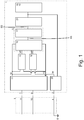
- the Figure 1 shows a schematic block diagram of a protective conductor monitoring device 1 of a power distribution device.
- the Figures 2 . 3 and 4 each show specific circuits that can be used as the protective conductor monitoring device 1.
- the in the Figures 2 and 3 Specified type designations and values for the individual components are to be understood as examples only.
- the circuits shown are not limited to these types and values given as examples.
- the in the Figures 2 and 3 The voltage source V1 shown is not necessarily part of the protective conductor monitoring device 1 described. Instead, the voltage source V1 can stand for the AC voltage or mains voltage present between the phase conductor 8 and the neutral conductor 10 of the electrical line 2.
- the power distribution device serves to supply one or more electrical consumers with a mains voltage and to establish electrical contact between the electrical consumer (s) and a protective conductor.
- the current distribution device also serves to detect a protective conductor fault.
- the current distribution device comprises a protective conductor monitoring device 1.
- a protective conductor monitoring device 1 An example of a protective conductor monitoring device 1 is shown in FIG Figure 1 shown.
- the protective conductor monitoring device 1 comprises in particular a rectifier arrangement 11, a first circuit arrangement 12 and a second circuit arrangement 13.
- the rectifier arrangement 11 has as input a second connection point 7 and a third connection point 9. These connection points are connected or connectable to a phase conductor 8 and a neutral conductor 10 of an electrical line 2.
- an AC voltage is present at the input of the rectifier arrangement 11, which is converted by the rectifier arrangement 11 into a rectified voltage, which is output between the two output connections 14 and 15 of the rectifier arrangement 11.
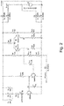
- the Figures 2 . 3 and 4 show specific circuit examples of the protective monitoring device 1.
- the rectifier arrangement 11 comprises a rectifier bridge formed from the diodes D1, D2, D3 and D4.
- the rectifier arrangement 11 also includes the resistors R1, R2 and R3 serving to limit the current, and the varistor U1, which limits the voltage drop between the output connections 14 and 15 to a maximum value.
- the resistors R1, R2 and R3, and the varistor U1 represent optional features that are not absolutely necessary to solve the task.
- the circuit arrangements 12 and 13 are designed as voltage dividers.
- the first circuit arrangement 12 comprises the resistors R7, R15 and optionally R9 and provides the measurement potential MP at the node P9, while the second circuit arrangement comprises the resistors R11 and R10 and provides the comparison potential VP at the node P7.
- the resistance values R7, R15, R9, R11 and R10 are selected such that a precise threshold value is defined for the protective conductor resistance, from which the protective conductor monitoring device 1 detects a protective conductor fault. In particular lies in the Figure 2 shown example the sum of the resistance values R15 and R9 2.2 kOhm below the resistance value of R6.
- the protective conductor monitoring device 1 outputs a signal which indicates a protective conductor fault, starting at a resistance of approximately 2.2 kOhm between the connection point 3 and the ground 6 of the protective conductor.
- the sensitivity of the protective conductor monitoring device 1 can thus be set precisely by choosing the resistance values of the voltage dividers.
- a diode D5 can also be provided between the first connection point 3 or AP and the first voltage divider.
- This diode is preferably of the same type as the diode D3 of the rectifier bridge and ensures that the lower connection points of the voltage dividers have approximately the same potential if the resistance on the protective conductor is negligible and the grounding of the protective conductor has approximately the same potential as the neutral conductor.
- the measurement potential MP and the comparison potential VP are fed to the respective inputs of the comparator 16.
- the comparator 16 can be designed as a differential amplifier which comprises the transistors Q1 and Q2 and the resistors R8, R5 and R6.
- a current mirror can also be provided, which mirrors the current from the collector of transistor Q2 to the collector of transistor Q1.
- the transistors Q1 and Q2 are preferably designed as PNP transistors.
- the comparator 16 outputs the comparator signal KS at its output. Im in the Figure 3 Example shown, this comparator signal KS can be tapped at the output P5 of the differential amplifier. If the measurement potential MP at node P9 is above the comparison potential VP at node P7, the output P5 of the differential amplifier assumes a low voltage level. If the measurement potential is below the comparison potential, the output P5 assumes a high voltage level.
- the comparator signal KS that can be tapped at the output P5 of the differential amplifier is supplied to the memory element 17.
- the memory element 17 comprises the transistor Q3, the resistor R13, the capacitor C1 and preferably the resistor R12.
- the transistor Q3 is preferably designed as an NPN transistor.
- the base of the transistor Q3 is connected to the output P5 or KS of the differential amplifier via a resistor R12.
- the state of charge of the capacitor C1 or the voltage applied to the capacitor serves as the detection signal ES to detect a protective conductor fault.
- This has the advantage that a temporary tilting of the comparator 16 or the differential amplifier, which is not caused by a protective conductor fault, is filtered out to a certain extent.
- Such a temporary tilting of the comparator 16 can occur regularly in each period of the AC voltage supplied by the phase conductor 8.
- the potential present at the lower output terminal 15 of the rectifier arrangement 11 namely moves approximately between the potential of the neutral conductor 10 and the most negative value of the AC voltage supplied by the phase conductor 8 with respect to this potential.
- the comparison potential VP can accordingly be drawn below the potential of the neutral conductor 10.
- the measurement potential MP can only be pulled down to the potential of the grounding 6 of the protective conductor PE during a period of the alternating voltage, which potential generally corresponds to the potential of the neutral conductor 10.
- the comparison potential VP is smaller than the measurement potential MP; i.e. that the measurement potential MP exceeds the comparison potential VP, even if there is no protective conductor fault.
- the memory element 17 is now dimensioned such that this temporary tilting of the comparator during a period of the AC voltage carried by the phase conductor 8 is not sufficient to charge the capacitor to such an extent that the first switching element connected to the memory element 17 is switched.
- the first switching element 21 is designed as a transistor Q4.
- Transistor Q4 is preferably an NPN transistor.
- the capacitor C1 and the resistor R13 are now designed such that the periodic tilting of the differential amplifier or the periodic blocking of the transistor Q3 is not sufficient to charge the capacitor C1 during a period to such an extent that the transistor Q4 is turned on.
- the measurement potential MP or the node P9 moves below the comparison potential VP or the node P7 at least once per period of the AC voltage carried by the phase conductor 8. Accordingly, the memory element 17 or the capacitor C1 is discharged at least once per period, provided that there is no protective conductor fault.
- the signal element 18 and / or the second switching element 19 and / or the decoupling element 20 are actuated.
- the signal element is formed by a light emitting diode D7 and / or a buzzer or speaker R4.
- a relay or that in the Figure 1 Shown second switching element 19 may be provided, which serves to cause the connection between the electrical line when actuated by the first switching element 21 2 and one or more electrical consumers connected to the power distribution device.
- the decoupling element can be designed as a transistor, preferably as an NPN transistor Q5. If the transistor Q4 or the first switching element 21 is turned on, the decoupling element 20 or the transistor Q5 blocks. This prevents voltages being coupled into the protective conductor 4 in the event of a protective conductor fault.
- the Figure 5 shows a schematic representation of an exemplary power distribution device 100.
- the power distribution device 100 is shown as a portable power distribution device.
- the current distribution device 100 can also be designed to be stationary.
- the socket 23 shown and the power plug 22 can be designed as fixed connection terminals of a stationary power distribution device. The following description therefore also relates in analogy to the case where the power distribution device is designed to be movable.
- the current distribution device 100 comprises the protective conductor monitoring device 1 described above, a mains plug 22, a residual current circuit breaker RCD and a socket 23.
- the protective conductor monitoring device 1 here comprises at least the features according to the invention described at the beginning and in particular a signal element 18 designed as an LED or loudspeaker and / or a second one Switching element 19 of the type described above.
- the power distribution device can be plugged into the permanently installed socket 24 using the mains plug 22 in order to be electrically connected to the electrical line 2 and to supply an electrical consumer with the line voltage provided by the electrical line 2 via the socket 23.
- the protective conductor monitoring device comprises the connection points 3, 7 and 9, which are connected to the contacts of the mains plug and can thus also establish an electrical connection with the phase conductor 7, the neutral conductor 9 and the protective conductor 4 of the electrical line 2.
- the protective conductor monitoring device 1 monitors the resistance between the first connection point 3 and the grounding of the protective conductor 4. If the monitored resistance exceeds a predetermined threshold value, the protective conductor monitoring device 1 transmits the signal element 18 emits an optical and / or acoustic warning signal. Furthermore, the protective conductor monitoring device 1, via the residual current circuit breaker RCD, causes the socket 23 to be disconnected from the electrical line 2.
- the residual current circuit breaker, RCD is preferably designed as a DI switch or FI switch.
- the residual current circuit breaker can be actuated by the second switching element 19 in order to disconnect electrical loads connected to the current distribution device in the event of a protective conductor fault.
- the current distribution device can have a phase monitoring module (not shown), which is designed to detect, preferably based on capacitive phase field detection, that the protective conductor 4 carries an AC voltage, and in this case to cause an electrical connection between one electrical consumer and the phase conductor 8, the neutral conductor 10 and / or the protective conductor 4 separately becomes.
- a phase monitoring module (not shown), which is designed to detect, preferably based on capacitive phase field detection, that the protective conductor 4 carries an AC voltage, and in this case to cause an electrical connection between one electrical consumer and the phase conductor 8, the neutral conductor 10 and / or the protective conductor 4 separately becomes.
- this can be done in the DE 10 2013 017 252 A1 described monitoring module or a device similar to this module can be used.
- the electrical line 2 comprises at least one phase conductor 8.
- the electrical line 2 can also comprise a plurality of phase conductors 8.
- the electrical line 2 can comprise three phase conductors.
- the second switching element 19 can be designed to separate an electrical consumer from all phase conductors of the electrical line 2.
- the embodiment also relates to a permanently testing protective device for mains power connections in the absence of a protective conductor. If the missing PE earthing is detected, it warns with an optical and / or acoustic tone.
- the embodiment also relates to universal electronics for protective conductor monitoring. This detects errors in the low-resistance range through a further stage of high-voltage transistors 2N3439, which are connected as differential amplifiers.
- the protective conductor monitoring device can therefore detect the slightest changes in the protective conductor resistance and thus a deterioration in the earth connection.
- the detection of the protective conductor resistance is more sensitive than before and as the known state of the art can.
- the embodiment further relates to a detection of a live protective conductor and also warns optically and / or acoustically.
- the user is neither warned nor protected whether everything is in order or whether the protective conductor arrives at the primarily tapped supply socket, since otherwise the user of the circuit can only recognize this by measurement.
- This developed protective device checks and monitors, primarily for (1) the previously defective socket used at work, in the office or on the construction site via the plug connection of the plug.
- the mains fault is clearly indicated by a red LED with the words Warning: Danger to life protective conductor interrupted.
- the sound is made loud with a piezopieper.
- This safety technology can also be switched off by relays.
- the technology is a further development, which is much more sensitive than the previous ones and also warns if the "PE" network phase leads.
- a test button gives the opportunity to occasionally test the circuit for tripping. Furthermore, it is easily possible within the circuit to integrate self-monitoring for its failure.
- This embodiment also relates to a technique for protective conductor monitoring, which has the following special features: On the one hand, reliable permanent monitoring for the detection of a badly contacted or non-existing interrupted protective conductor, solved in such a way that this is detected even in the low-resistance range.
- the embodiment relates to universal network monitoring electronics, which permanently detects the monitoring of the protective conductor “PE” or the presence of a “low-resistance PE connection” at mains power connections and immediately reacts in a safety-related manner in the event of a lack of earth, poor contact connection and no voltage. "PE” must be present.
- the embodiment relates to a circuit which can detect the "PE" in the low-resistance range.
- Previously known circuits work in the range of several 100 kOhm with the detection of the protective conductor in order - available.
- the embodiment recognizes "PE” connections through oxidized or poor contact transfers or the absence of the "PE”.
- the monitoring electronics When used in cable drums, the monitoring electronics should be coupled to an FI switch, which then whose load contacts perform an all-pole shutdown (including PE), a so-called PRCD-S functionality.
- This electronic circuit recognizes in the low-resistance range with its 5 high-voltage transistors e.g. 2N3439 NPN and 2N5416 PNP as differential amplifiers switch even small changes in the protective conductor resistance, thus a deterioration of the earth connection. This results in a highly sensitive detection of the protective conductor resistance than previous circuit techniques can do. High-voltage transistors that work safely with these high voltages should therefore be used here.
- the embodiment further relates to a detection of a live protective conductor and also warns optically and acoustically, or switches off.
- This protective device therefore primarily checks and monitors (1) the previously defective socket used at work, in the office or on the construction site from the supply point via the plug connection of the plug.
- An additional test button would give the opportunity to occasionally test the circuit for tripping.
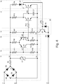
- V1 symbolizes the connections of the 230V mains voltage.
- V1 controls a bridge rectifier circuit consisting of diodes D1 to D4.
- the positive pole of the pulsating DC voltage thus generated is located at the "Bridge Rectifier Plus” point and the negative pole at the "Bridge Rectifier Minus” point.
- the pulsating DC voltage is used to power the rest of the circuit.
- the rest of the circuit is energized by LED D7 (alarm status) if point AP (corresponds to the PE connection) is connected with high impedance or not at all to earth potential. The LED then lights up, indicating the faulty condition to the user.
- R4 can represent a buzzer, or a microrelay that bridges an RCD with a series resistor, so that it switches off the network with its contacts.
- the LED is not energized and remains dark (idle state), the buzzer does not emit an alarm tone, a relay here would not respond.
- the blocking section of Q5 keeps undesired, high-impedance coupling of the phase away from the PE contact.
- the idle state (LED D7 de-energized) is described below.
- AP is connected to earth potential with low resistance.
- the base of Q5 is energized via LED D7, Q5 switches through. This lowers the differential amplifier input P9 below the potential of P7, Q1 turns on and energizes the base of Q3.
- Q3 switches through and thus blocks Q4.
- LED D7 (except for a very low dark current to control the base of Q5) is kept currentless and remains in the non-illuminating state.
- the alarm status (LED D7 energized) is described below. If a corresponding resistance is established between AP and the earth potential, the differential amplifier input P9 is raised above the potential of P7, Q2 conducts and Q1 blocks, the base of Q3 is thus de-energized. The base of Q4 is energized via R13 and Q4 opens. The LED D7 is thus supplied with current, lights up and thus indicates the alarm status. By changing the ohmic resistance R15, the sensitivity of the response behavior can be determined in order to detect in the range of approx. 50-100 ohms.
Landscapes
- Physics & Mathematics (AREA)
- General Physics & Mathematics (AREA)
- Emergency Protection Circuit Devices (AREA)
Claims (11)
- Dispositif de répartition de l'alimentation (100), conçu de manière fixe ou mobile, en particulier prise, bloc multiprise, adaptateur, enrouleur de câble, armoire électrique de chantier, câble de raccordement ou rallonge, qui sert à fournir à un ou plusieurs consommateurs électriques une tension secteur qui est acheminée par un câble électrique (2) équipé d'un conducteur de protection (4), avec un dispositif de surveillance de conducteur de protection (1) pour détecter un défaut de conducteur de protection sur le câble électrique (2), dans lequel le dispositif de surveillance de conducteur de protection (1) comprend un premier point de raccordement (3) qui peut être relié ou est relié électriquement au conducteur de protection (4), dans lequel le dispositif de surveillance de conducteur de protection (1) comprend en outre : un premier circuit (12), qui est conçu pour, dans un état dans lequel le premier point de raccordement (3) est relié au conducteur de protection (4), fournir un potentiel de mesure (MP) qui dépend de la résistance entre le premier point de raccordement (3) et la terre (6) du conducteur de protection (4), un second circuit (13), qui est conçu pour fournir un potentiel de comparaison (VP), un circuit comparateur (5) comprenant un comparateur (16), qui est conçu pour comparer le potentiel de mesure (MP) au potentiel de comparaison (VP) et fournir en fonction du résultat de la comparaison un signal de détection (ES) pour détecter un défaut de conducteur de protection, un deuxième point de raccordement (7) qui peut être relié ou est relié électriquement à un conducteur de phase (8) du câble électrique (2), un troisième point de raccordement (9) qui peut être relié ou est relié électriquement à un conducteur neutre (10) du câble électrique (2), et un ensemble redresseur (11) équipé de préférence d'un pont redresseur, qui est conçu pour transformer une tension alternative présente entre le deuxième point de raccordement (7) et le troisième point de raccordement (9) en une tension redressée et l'acheminer en tant que tension d'alimentation au circuit comparateur (5) via la sortie de l'ensemble redresseur (11), dans lequel le premier circuit (12) est conçu pour dériver le potentiel de mesure (MP) d'une tension qui est présente entre une borne de sortie (14) de l'ensemble redresseur (11) et un nœud (3a) relié électriquement au premier point de raccordement (3), et fournir le potentiel de mesure (MP) au circuit comparateur (5), et le second circuit (13) est conçu pour dériver le potentiel de comparaison (VP) de la tension redressée présente entre les deux bornes de sortie (14, 15) de l'ensemble redresseur (11) et pour le fournir au circuit comparateur (5).
- Dispositif de répartition de l'alimentation (100) selon la revendication 1, caractérisé en ce que le comparateur (16) comprend un amplificateur différentiel et le premier circuit (12) et le second circuit (13) sont conçus pour acheminer le potentiel de mesure (MP) et le potentiel de comparaison (VP) aux entrées de l'amplificateur différentiel.
- Dispositif de répartition de l'alimentation (100) selon la revendication 1 ou 2, caractérisé en ce que le premier circuit (12) comprend un premier diviseur de tension avec de préférence au moins deux résistances, dans lequel le premier diviseur de tension est monté entre la borne de sortie de l'ensemble redresseur (11) et le nœud (3a) relié électriquement au premier point de raccordement (3) et est conçu pour diviser la tension présente via le premier diviseur de tension en un premier rapport prédéterminé et pour fournir le potentiel résultant au circuit comparateur (5) en tant que potentiel de mesure (MP).
- Dispositif de répartition de l'alimentation (100) selon l'une des revendications précédentes, caractérisé en ce que le second circuit (13) comprend un second diviseur de tension avec de préférence au moins deux résistances, dans lequel le second diviseur de tension est monté entre les deux bornes de sortie (14, 15) de l'ensemble redresseur (11) et est conçu pour diviser la tension redressée en un deuxième rapport prédéterminé et fournir le potentiel résultant au circuit comparateur (5) en tant que potentiel de comparaison (VP).
- Dispositif de répartition de l'alimentation (100) selon l'une des revendications précédentes, caractérisé en ce que le circuit comparateur (5) comprend en outre un élément de mémoire (17), de préférence un élément passe-bas, le comparateur (16) est conçu pour comparer le potentiel de mesure (MP) au potentiel de comparaison (VP) et pour délivrer un signal de comparateur (KS) en fonction du résultat de la comparaison, le circuit comparateur est conçu pour charger ou décharger l'élément de mémoire (17) en fonction du signal de comparateur (KS), et pour fournir le signal de détection (ES) en fonction de l'état de charge de l'élément de mémoire (17), dans lequel l'élément de mémoire (17) comprend de préférence un condensateur et le signal de détection (ES) dépend de préférence de la tension qui chute via le condensateur.
- Dispositif de répartition de l'alimentation (100) selon l'une des revendications précédentes, caractérisé en ce que le dispositif de surveillance de conducteur de protection (1) comprend en outre : au moins un élément de signalisation (18) comprenant de préférence une LED et/ou un haut-parleur, qui est conçu pour, lorsqu'il est activé, délivrer un signal électrique, optique et/ou acoustique pour indiquer un défaut de conducteur de protection, et un premier élément de commutation (21) qui est conçu pour activer l'élément de signalisation (18) dans le cas où le signal de détection (ES) dépasse ou tombe sous une valeur seuil prédéterminée.
- Dispositif de répartition de l'alimentation (100) selon l'une des revendications précédentes, caractérisé en ce que le dispositif de surveillance de conducteur de protection (1) comprend en outre : un second élément de commutation (19), comprenant de préférence un relais, pour commander un dispositif de protection contre les courants de défaut (RCD), qui est conçu pour, lorsqu'il est activé, faire en sorte que soit interrompue une liaison électrique entre les un ou plusieurs consommateurs électriques et le conducteur de phase (8), le conducteur neutre (10) et/ou le conducteur de protection (4), et un premier élément de commutation (21) qui est conçu pour activer le second élément de commutation (19) dans le cas où le signal de détection (ES) dépasse ou tombe sous une valeur seuil prédéterminée.
- Dispositif de répartition de l'alimentation (100) selon l'une des revendications précédentes, caractérisé en ce que le dispositif de surveillance de conducteur de protection (1) comprend en outre : un élément de découplage (20), équipé de préférence d'un transistor, qui est conçu pour, lorsqu'il est activé, commuter à une impédance élevée la liaison électrique entre le premier circuit (12) et le premier point de raccordement (3), et un premier élément de commutation (21) qui est conçu pour activer l'élément de découplage (20) dans le cas où le signal de détection (ES) dépasse ou tombe sous une valeur seuil prédéterminée.
- Dispositif de répartition de l'alimentation (100) selon l'une des revendications précédentes, caractérisé en ce que le dispositif de surveillance de conducteur de protection (1) comprend en outre : un module de surveillance de phase qui est conçu pour détecter, de préférence à l'aide d'une détection capacitive de champ de phase, que le conducteur de protection (4) est parcouru par une tension alternative, et pour, dans ce cas, faire en sorte que soit interrompue une liaison électrique entre un consommateur électrique et le conducteur de phase (8), le conducteur neutre (10) et/ou le conducteur de protection (4).
- Dispositif de répartition de l'alimentation (100) selon l'une des revendications précédentes, caractérisé par une fiche secteur (22), dans lequel le premier point de raccordement (3), le deuxième point de raccordement (7) et le troisième point de raccordement (9) sont reliés électriquement aux contacts respectifs de la fiche secteur.
- Procédé de surveillance de conducteur de protection pour détecter, au moyen d'un dispositif de répartition de l'alimentation (100) selon l'une des revendications précédentes, un défaut de conducteur de protection sur un câble électrique (2) équipé d'un conducteur de protection (4), caractérisé par les étapes suivantes : fourniture, par le premier circuit (12), d'un potentiel de mesure (MP) qui dépend de la résistance entre le premier point de raccordement (3) relié au conducteur de protection (4) du câble électrique (2) et la terre (6) du câble électrique (2), fourniture, par le second circuit (13), d'un potentiel de comparaison (VP), comparaison, par le circuit comparateur (5), du potentiel de mesure (MP) avec le potentiel de comparaison (VP), et délivrance, en fonction du résultat de la comparaison, d'un signal de détection (ES) pour détecter un défaut de conducteur de protection.
Priority Applications (1)
| Application Number | Priority Date | Filing Date | Title |
|---|---|---|---|
| PL15167563T PL2945240T4 (pl) | 2014-05-13 | 2015-05-13 | Urządzenie rozdzielacza prądu z urządzeniem kontrolnym przewodu ochronnego i sposób |
Applications Claiming Priority (2)
| Application Number | Priority Date | Filing Date | Title |
|---|---|---|---|
| DE102014006849 | 2014-05-13 | ||
| DE102015002554 | 2015-03-02 |
Publications (2)
| Publication Number | Publication Date |
|---|---|
| EP2945240A1 EP2945240A1 (fr) | 2015-11-18 |
| EP2945240B1 true EP2945240B1 (fr) | 2020-02-26 |
Family
ID=53199800
Family Applications (1)
| Application Number | Title | Priority Date | Filing Date |
|---|---|---|---|
| EP15167563.4A Active EP2945240B1 (fr) | 2014-05-13 | 2015-05-13 | Dispositif de répartition de l'alimentation, dispositif de surveillance de conducteur de mise à la terre et procédé |
Country Status (3)
| Country | Link |
|---|---|
| EP (1) | EP2945240B1 (fr) |
| ES (1) | ES2792925T3 (fr) |
| PL (1) | PL2945240T4 (fr) |
Families Citing this family (4)
| Publication number | Priority date | Publication date | Assignee | Title |
|---|---|---|---|---|
| DE102016217712A1 (de) | 2016-09-16 | 2018-03-22 | Te Connectivity Germany Gmbh | Überwachungsvorrichtung und Verfahren zum Überwachen einer Impedanz eines Schutzleiters sowie Ladekontrolleinheit |
| DE202018104044U1 (de) * | 2018-07-13 | 2019-10-15 | Wago Verwaltungsgesellschaft Mbh | Erdleiter-Überwachung |
| EP3817172A1 (fr) | 2019-10-31 | 2021-05-05 | Hugo Brennenstuhl GmbH & Co. Kommanditgesellschaft | Agencement de surveillance d'un conducteur de protection, dispositif de distribution électrique et procédé de surveillance d'un conducteur de protection |
| EP3817173B1 (fr) | 2019-10-31 | 2023-10-18 | Hugo Brennenstuhl GmbH & Co. Kommanditgesellschaft | Agencement de surveillance d'un conducteur de protection, dispositif de distribution de courant et procédé d'exécution d'un test de fonctionnement |
Family Cites Families (6)
| Publication number | Priority date | Publication date | Assignee | Title |
|---|---|---|---|---|
| GB8429523D0 (en) * | 1984-11-22 | 1985-01-03 | Indep Tv News Ltd | Earth validity tester |
| IL109607A (en) * | 1994-05-10 | 1997-04-15 | Hayim Nevo | Grounding fault detection system |
| DE29519212U1 (de) * | 1995-12-04 | 1996-01-25 | Siemens Ag | Schaltungsanordnung zur Erdungsüberwachung und zum Schutz vor gefährlichen Körperströmen, insbesondere für Geräte mit vorgeschriebenem Potentialausgleich in TT-Netzen |
| DE19618279A1 (de) | 1996-05-07 | 1997-11-13 | Kopp Heinrich Ag | DI-Schutzschalteinrichtung |
| DE202012001300U1 (de) | 2012-02-10 | 2012-05-16 | Peter Brandes | PE-Überwachende Schutzeinrichtung für ortsveränderliche Stromanschlüsse - Kabeltrommel - |
| DE102013017252A1 (de) | 2013-10-17 | 2015-04-23 | Peter Brandes | Überwachungselektronik - Kabeltrommel Schutzleiterüberwachung u. Stromverteiler-Modul |
-
2015
- 2015-05-13 ES ES15167563T patent/ES2792925T3/es active Active
- 2015-05-13 PL PL15167563T patent/PL2945240T4/pl unknown
- 2015-05-13 EP EP15167563.4A patent/EP2945240B1/fr active Active
Non-Patent Citations (1)
| Title |
|---|
| None * |
Also Published As
| Publication number | Publication date |
|---|---|
| ES2792925T3 (es) | 2020-11-12 |
| EP2945240A1 (fr) | 2015-11-18 |
| PL2945240T3 (pl) | 2020-08-24 |
| PL2945240T4 (pl) | 2020-10-19 |
Similar Documents
| Publication | Publication Date | Title |
|---|---|---|
| DE112012001189B4 (de) | Verfahren, Systeme und Einrichtungen zum Erkennen paralleler elektrischer Fehlerlichtbögen | |
| DE3215147C2 (fr) | ||
| DE102015121568A1 (de) | System und verfahren für eine kontaktmessschaltung | |
| EP3059828B1 (fr) | Dispositif et procede de detection de courant differentiel | |
| EP2945240B1 (fr) | Dispositif de répartition de l'alimentation, dispositif de surveillance de conducteur de mise à la terre et procédé | |
| DE602004002588T2 (de) | Verfahren und sicherheitseinrichtung für eine erdfehlerschutzschaltung | |
| DE19618279A1 (de) | DI-Schutzschalteinrichtung | |
| WO2014184107A1 (fr) | Procédé et dispositif de mesure de la résistance de ligne de câbles de commande de systèmes de signalisation de dangers et de commande | |
| WO2013024029A2 (fr) | Appareil de protection contre les surtensions pourvu d'un dispositif de mesure pour contrôler les éléments de protection contre les surtensions | |
| DE102014005524B4 (de) | Unterbrechung eines Stromes | |
| DE2328881B2 (fr) | ||
| AT507224B1 (de) | Fehlerstromschutzschalter | |
| CH618801A5 (fr) | ||
| DE102011107734B4 (de) | Schaltungsanordnung zum Schalten eines Relais in einen sicheren Schaltzustand | |
| EP3016225B1 (fr) | Dispositif de reconnaissance et procédé de reconnaissance d'états défectueux d'un conducteur de mise à la terre | |
| AT13822U1 (de) | Überwachungseinrichtung für ein isoliert aufgebautes netz einer photovoltaikanlage | |
| DE102010037995B4 (de) | Stromversorgungsgerät und Stromversorgungssystem mit ebensolchem | |
| WO2013092815A1 (fr) | Appareil de mesure d'impédance | |
| DE102012111615A1 (de) | Fehlerstromschutzschalter | |
| DE102018216950A1 (de) | Schaltungsanordnung zum sicheren Betrieb eines Hochvoltsystems | |
| EP2347490B1 (fr) | Commutateur de protection contre les courants de défaut | |
| EP3048685B1 (fr) | Dispositif de protection de courant de fuite et procédé de commutation de contacts de commutation du dispositif de protection de courant de fuite | |
| EP0678961B1 (fr) | Circuit reconnaissant et affichant l'interruption d'un conducteur | |
| DE60009752T2 (de) | Verbesserte elektronische fehlerstromschutzvorrichtung | |
| EP2237057A1 (fr) | Dispositif d'analyse destiné à l'analyse d'un réseau électrique |
Legal Events
| Date | Code | Title | Description |
|---|---|---|---|
| PUAI | Public reference made under article 153(3) epc to a published international application that has entered the european phase |
Free format text: ORIGINAL CODE: 0009012 |
|
| AK | Designated contracting states |
Kind code of ref document: A1 Designated state(s): AL AT BE BG CH CY CZ DE DK EE ES FI FR GB GR HR HU IE IS IT LI LT LU LV MC MK MT NL NO PL PT RO RS SE SI SK SM TR |
|
| AX | Request for extension of the european patent |
Extension state: BA ME |
|
| 17P | Request for examination filed |
Effective date: 20160517 |
|
| RBV | Designated contracting states (corrected) |
Designated state(s): AL AT BE BG CH CY CZ DE DK EE ES FI FR GB GR HR HU IE IS IT LI LT LU LV MC MK MT NL NO PL PT RO RS SE SI SK SM TR |
|
| STAA | Information on the status of an ep patent application or granted ep patent |
Free format text: STATUS: EXAMINATION IS IN PROGRESS |
|
| 17Q | First examination report despatched |
Effective date: 20180423 |
|
| GRAP | Despatch of communication of intention to grant a patent |
Free format text: ORIGINAL CODE: EPIDOSNIGR1 |
|
| STAA | Information on the status of an ep patent application or granted ep patent |
Free format text: STATUS: GRANT OF PATENT IS INTENDED |
|
| INTG | Intention to grant announced |
Effective date: 20190819 |
|
| GRAS | Grant fee paid |
Free format text: ORIGINAL CODE: EPIDOSNIGR3 |
|
| GRAA | (expected) grant |
Free format text: ORIGINAL CODE: 0009210 |
|
| STAA | Information on the status of an ep patent application or granted ep patent |
Free format text: STATUS: THE PATENT HAS BEEN GRANTED |
|
| AK | Designated contracting states |
Kind code of ref document: B1 Designated state(s): AL AT BE BG CH CY CZ DE DK EE ES FI FR GB GR HR HU IE IS IT LI LT LU LV MC MK MT NL NO PL PT RO RS SE SI SK SM TR |
|
| REG | Reference to a national code |
Ref country code: GB Ref legal event code: FG4D Free format text: NOT ENGLISH |
|
| REG | Reference to a national code |
Ref country code: CH Ref legal event code: EP |
|
| REG | Reference to a national code |
Ref country code: AT Ref legal event code: REF Ref document number: 1238812 Country of ref document: AT Kind code of ref document: T Effective date: 20200315 |
|
| REG | Reference to a national code |
Ref country code: IE Ref legal event code: FG4D Free format text: LANGUAGE OF EP DOCUMENT: GERMAN |
|
| REG | Reference to a national code |
Ref country code: DE Ref legal event code: R096 Ref document number: 502015011826 Country of ref document: DE |
|
| REG | Reference to a national code |
Ref country code: CH Ref legal event code: NV Representative=s name: TROESCH SCHEIDEGGER WERNER AG, CH |
|
| REG | Reference to a national code |
Ref country code: NL Ref legal event code: FP |
|
| REG | Reference to a national code |
Ref country code: SE Ref legal event code: TRGR |
|
| PG25 | Lapsed in a contracting state [announced via postgrant information from national office to epo] |
Ref country code: FI Free format text: LAPSE BECAUSE OF FAILURE TO SUBMIT A TRANSLATION OF THE DESCRIPTION OR TO PAY THE FEE WITHIN THE PRESCRIBED TIME-LIMIT Effective date: 20200226 Ref country code: NO Free format text: LAPSE BECAUSE OF FAILURE TO SUBMIT A TRANSLATION OF THE DESCRIPTION OR TO PAY THE FEE WITHIN THE PRESCRIBED TIME-LIMIT Effective date: 20200526 Ref country code: RS Free format text: LAPSE BECAUSE OF FAILURE TO SUBMIT A TRANSLATION OF THE DESCRIPTION OR TO PAY THE FEE WITHIN THE PRESCRIBED TIME-LIMIT Effective date: 20200226 |
|
| REG | Reference to a national code |
Ref country code: LT Ref legal event code: MG4D |
|
| PG25 | Lapsed in a contracting state [announced via postgrant information from national office to epo] |
Ref country code: LV Free format text: LAPSE BECAUSE OF FAILURE TO SUBMIT A TRANSLATION OF THE DESCRIPTION OR TO PAY THE FEE WITHIN THE PRESCRIBED TIME-LIMIT Effective date: 20200226 Ref country code: IS Free format text: LAPSE BECAUSE OF FAILURE TO SUBMIT A TRANSLATION OF THE DESCRIPTION OR TO PAY THE FEE WITHIN THE PRESCRIBED TIME-LIMIT Effective date: 20200626 Ref country code: GR Free format text: LAPSE BECAUSE OF FAILURE TO SUBMIT A TRANSLATION OF THE DESCRIPTION OR TO PAY THE FEE WITHIN THE PRESCRIBED TIME-LIMIT Effective date: 20200527 Ref country code: HR Free format text: LAPSE BECAUSE OF FAILURE TO SUBMIT A TRANSLATION OF THE DESCRIPTION OR TO PAY THE FEE WITHIN THE PRESCRIBED TIME-LIMIT Effective date: 20200226 Ref country code: BG Free format text: LAPSE BECAUSE OF FAILURE TO SUBMIT A TRANSLATION OF THE DESCRIPTION OR TO PAY THE FEE WITHIN THE PRESCRIBED TIME-LIMIT Effective date: 20200526 |
|
| PG25 | Lapsed in a contracting state [announced via postgrant information from national office to epo] |
Ref country code: RO Free format text: LAPSE BECAUSE OF FAILURE TO SUBMIT A TRANSLATION OF THE DESCRIPTION OR TO PAY THE FEE WITHIN THE PRESCRIBED TIME-LIMIT Effective date: 20200226 Ref country code: CZ Free format text: LAPSE BECAUSE OF FAILURE TO SUBMIT A TRANSLATION OF THE DESCRIPTION OR TO PAY THE FEE WITHIN THE PRESCRIBED TIME-LIMIT Effective date: 20200226 Ref country code: PT Free format text: LAPSE BECAUSE OF FAILURE TO SUBMIT A TRANSLATION OF THE DESCRIPTION OR TO PAY THE FEE WITHIN THE PRESCRIBED TIME-LIMIT Effective date: 20200719 Ref country code: LT Free format text: LAPSE BECAUSE OF FAILURE TO SUBMIT A TRANSLATION OF THE DESCRIPTION OR TO PAY THE FEE WITHIN THE PRESCRIBED TIME-LIMIT Effective date: 20200226 Ref country code: EE Free format text: LAPSE BECAUSE OF FAILURE TO SUBMIT A TRANSLATION OF THE DESCRIPTION OR TO PAY THE FEE WITHIN THE PRESCRIBED TIME-LIMIT Effective date: 20200226 Ref country code: SM Free format text: LAPSE BECAUSE OF FAILURE TO SUBMIT A TRANSLATION OF THE DESCRIPTION OR TO PAY THE FEE WITHIN THE PRESCRIBED TIME-LIMIT Effective date: 20200226 Ref country code: SK Free format text: LAPSE BECAUSE OF FAILURE TO SUBMIT A TRANSLATION OF THE DESCRIPTION OR TO PAY THE FEE WITHIN THE PRESCRIBED TIME-LIMIT Effective date: 20200226 Ref country code: DK Free format text: LAPSE BECAUSE OF FAILURE TO SUBMIT A TRANSLATION OF THE DESCRIPTION OR TO PAY THE FEE WITHIN THE PRESCRIBED TIME-LIMIT Effective date: 20200226 |
|
| REG | Reference to a national code |
Ref country code: ES Ref legal event code: FG2A Ref document number: 2792925 Country of ref document: ES Kind code of ref document: T3 Effective date: 20201112 |
|
| REG | Reference to a national code |
Ref country code: DE Ref legal event code: R097 Ref document number: 502015011826 Country of ref document: DE |
|
| PLBE | No opposition filed within time limit |
Free format text: ORIGINAL CODE: 0009261 |
|
| STAA | Information on the status of an ep patent application or granted ep patent |
Free format text: STATUS: NO OPPOSITION FILED WITHIN TIME LIMIT |
|
| PG25 | Lapsed in a contracting state [announced via postgrant information from national office to epo] |
Ref country code: MC Free format text: LAPSE BECAUSE OF FAILURE TO SUBMIT A TRANSLATION OF THE DESCRIPTION OR TO PAY THE FEE WITHIN THE PRESCRIBED TIME-LIMIT Effective date: 20200226 |
|
| 26N | No opposition filed |
Effective date: 20201127 |
|
| PG25 | Lapsed in a contracting state [announced via postgrant information from national office to epo] |
Ref country code: SI Free format text: LAPSE BECAUSE OF FAILURE TO SUBMIT A TRANSLATION OF THE DESCRIPTION OR TO PAY THE FEE WITHIN THE PRESCRIBED TIME-LIMIT Effective date: 20200226 |
|
| PG25 | Lapsed in a contracting state [announced via postgrant information from national office to epo] |
Ref country code: LU Free format text: LAPSE BECAUSE OF NON-PAYMENT OF DUE FEES Effective date: 20200513 |
|
| PG25 | Lapsed in a contracting state [announced via postgrant information from national office to epo] |
Ref country code: IE Free format text: LAPSE BECAUSE OF NON-PAYMENT OF DUE FEES Effective date: 20200513 |
|
| PG25 | Lapsed in a contracting state [announced via postgrant information from national office to epo] |
Ref country code: TR Free format text: LAPSE BECAUSE OF FAILURE TO SUBMIT A TRANSLATION OF THE DESCRIPTION OR TO PAY THE FEE WITHIN THE PRESCRIBED TIME-LIMIT Effective date: 20200226 Ref country code: MT Free format text: LAPSE BECAUSE OF FAILURE TO SUBMIT A TRANSLATION OF THE DESCRIPTION OR TO PAY THE FEE WITHIN THE PRESCRIBED TIME-LIMIT Effective date: 20200226 Ref country code: CY Free format text: LAPSE BECAUSE OF FAILURE TO SUBMIT A TRANSLATION OF THE DESCRIPTION OR TO PAY THE FEE WITHIN THE PRESCRIBED TIME-LIMIT Effective date: 20200226 |
|
| PG25 | Lapsed in a contracting state [announced via postgrant information from national office to epo] |
Ref country code: MK Free format text: LAPSE BECAUSE OF FAILURE TO SUBMIT A TRANSLATION OF THE DESCRIPTION OR TO PAY THE FEE WITHIN THE PRESCRIBED TIME-LIMIT Effective date: 20200226 Ref country code: AL Free format text: LAPSE BECAUSE OF FAILURE TO SUBMIT A TRANSLATION OF THE DESCRIPTION OR TO PAY THE FEE WITHIN THE PRESCRIBED TIME-LIMIT Effective date: 20200226 |
|
| P01 | Opt-out of the competence of the unified patent court (upc) registered |
Effective date: 20230523 |
|
| PGFP | Annual fee paid to national office [announced via postgrant information from national office to epo] |
Ref country code: NL Payment date: 20230519 Year of fee payment: 9 Ref country code: IT Payment date: 20230531 Year of fee payment: 9 Ref country code: FR Payment date: 20230517 Year of fee payment: 9 Ref country code: ES Payment date: 20230621 Year of fee payment: 9 Ref country code: DE Payment date: 20230428 Year of fee payment: 9 Ref country code: CH Payment date: 20230602 Year of fee payment: 9 |
|
| PGFP | Annual fee paid to national office [announced via postgrant information from national office to epo] |
Ref country code: SE Payment date: 20230522 Year of fee payment: 9 Ref country code: PL Payment date: 20230413 Year of fee payment: 9 Ref country code: AT Payment date: 20230516 Year of fee payment: 9 |
|
| PGFP | Annual fee paid to national office [announced via postgrant information from national office to epo] |
Ref country code: BE Payment date: 20230517 Year of fee payment: 9 |
|
| PGFP | Annual fee paid to national office [announced via postgrant information from national office to epo] |
Ref country code: GB Payment date: 20230522 Year of fee payment: 9 |