EP2944965A1 - Rotatable cartridge for measuring a property of a biological sample - Google Patents
Rotatable cartridge for measuring a property of a biological sample Download PDFInfo
- Publication number
- EP2944965A1 EP2944965A1 EP14168042.1A EP14168042A EP2944965A1 EP 2944965 A1 EP2944965 A1 EP 2944965A1 EP 14168042 A EP14168042 A EP 14168042A EP 2944965 A1 EP2944965 A1 EP 2944965A1
- Authority
- EP
- European Patent Office
- Prior art keywords
- cartridge
- container
- cavity
- biological sample
- fluid
- Prior art date
- Legal status (The legal status is an assumption and is not a legal conclusion. Google has not performed a legal analysis and makes no representation as to the accuracy of the status listed.)
- Withdrawn
Links
- 239000012472 biological sample Substances 0.000 title claims abstract description 60
- 239000012530 fluid Substances 0.000 claims abstract description 133
- 238000005259 measurement Methods 0.000 claims abstract description 73
- 238000012545 processing Methods 0.000 claims abstract description 11
- 230000013011 mating Effects 0.000 claims abstract description 9
- 238000000034 method Methods 0.000 claims description 35
- 230000008569 process Effects 0.000 claims description 6
- 230000001070 adhesive effect Effects 0.000 claims description 2
- 238000012360 testing method Methods 0.000 description 43
- 238000004458 analytical method Methods 0.000 description 42
- 239000000523 sample Substances 0.000 description 28
- 239000003153 chemical reaction reagent Substances 0.000 description 23
- 239000007788 liquid Substances 0.000 description 14
- 238000013461 design Methods 0.000 description 8
- 230000033001 locomotion Effects 0.000 description 8
- 230000008901 benefit Effects 0.000 description 7
- 238000006243 chemical reaction Methods 0.000 description 7
- 230000003287 optical effect Effects 0.000 description 7
- 239000000126 substance Substances 0.000 description 7
- 238000005406 washing Methods 0.000 description 7
- 230000006870 function Effects 0.000 description 6
- 238000000926 separation method Methods 0.000 description 6
- 239000000243 solution Substances 0.000 description 6
- 239000002699 waste material Substances 0.000 description 5
- 239000012491 analyte Substances 0.000 description 4
- 210000004369 blood Anatomy 0.000 description 4
- 239000008280 blood Substances 0.000 description 4
- 230000008859 change Effects 0.000 description 4
- 210000003743 erythrocyte Anatomy 0.000 description 4
- 239000011159 matrix material Substances 0.000 description 4
- 230000009471 action Effects 0.000 description 3
- 238000004720 dielectrophoresis Methods 0.000 description 3
- 238000011010 flushing procedure Methods 0.000 description 3
- 239000011888 foil Substances 0.000 description 3
- 238000012544 monitoring process Methods 0.000 description 3
- 238000003541 multi-stage reaction Methods 0.000 description 3
- 238000003860 storage Methods 0.000 description 3
- 239000000758 substrate Substances 0.000 description 3
- 102000004190 Enzymes Human genes 0.000 description 2
- 108090000790 Enzymes Proteins 0.000 description 2
- 241000700605 Viruses Species 0.000 description 2
- 239000007864 aqueous solution Substances 0.000 description 2
- 210000001124 body fluid Anatomy 0.000 description 2
- 239000010839 body fluid Substances 0.000 description 2
- 238000004891 communication Methods 0.000 description 2
- 230000000984 immunochemical effect Effects 0.000 description 2
- 238000002032 lab-on-a-chip Methods 0.000 description 2
- 239000000463 material Substances 0.000 description 2
- 239000000203 mixture Substances 0.000 description 2
- 102000039446 nucleic acids Human genes 0.000 description 2
- 108020004707 nucleic acids Proteins 0.000 description 2
- 150000007523 nucleic acids Chemical class 0.000 description 2
- 239000010409 thin film Substances 0.000 description 2
- 238000009423 ventilation Methods 0.000 description 2
- WQZGKKKJIJFFOK-GASJEMHNSA-N Glucose Natural products OC[C@H]1OC(O)[C@H](O)[C@@H](O)[C@@H]1O WQZGKKKJIJFFOK-GASJEMHNSA-N 0.000 description 1
- 206010034719 Personality change Diseases 0.000 description 1
- 240000007643 Phytolacca americana Species 0.000 description 1
- 235000009074 Phytolacca americana Nutrition 0.000 description 1
- 102000007056 Recombinant Fusion Proteins Human genes 0.000 description 1
- 108010008281 Recombinant Fusion Proteins Proteins 0.000 description 1
- 239000002250 absorbent Substances 0.000 description 1
- 230000002745 absorbent Effects 0.000 description 1
- 230000001133 acceleration Effects 0.000 description 1
- 239000002253 acid Substances 0.000 description 1
- 239000000427 antigen Substances 0.000 description 1
- 102000036639 antigens Human genes 0.000 description 1
- 108091007433 antigens Proteins 0.000 description 1
- 238000003556 assay Methods 0.000 description 1
- 230000004888 barrier function Effects 0.000 description 1
- 239000011324 bead Substances 0.000 description 1
- 230000005540 biological transmission Effects 0.000 description 1
- 230000001413 cellular effect Effects 0.000 description 1
- 238000005345 coagulation Methods 0.000 description 1
- 230000015271 coagulation Effects 0.000 description 1
- 230000001419 dependent effect Effects 0.000 description 1
- 238000001514 detection method Methods 0.000 description 1
- 239000003599 detergent Substances 0.000 description 1
- 239000003085 diluting agent Substances 0.000 description 1
- 239000006185 dispersion Substances 0.000 description 1
- 238000000835 electrochemical detection Methods 0.000 description 1
- 238000006911 enzymatic reaction Methods 0.000 description 1
- 230000005294 ferromagnetic effect Effects 0.000 description 1
- 239000010408 film Substances 0.000 description 1
- 239000008103 glucose Substances 0.000 description 1
- 230000005484 gravity Effects 0.000 description 1
- 230000002209 hydrophobic effect Effects 0.000 description 1
- 230000006872 improvement Effects 0.000 description 1
- 238000001746 injection moulding Methods 0.000 description 1
- 230000010354 integration Effects 0.000 description 1
- 230000002452 interceptive effect Effects 0.000 description 1
- 238000001459 lithography Methods 0.000 description 1
- 239000000696 magnetic material Substances 0.000 description 1
- 238000004519 manufacturing process Methods 0.000 description 1
- 230000007246 mechanism Effects 0.000 description 1
- 239000002184 metal Substances 0.000 description 1
- VNWKTOKETHGBQD-UHFFFAOYSA-N methane Chemical compound C VNWKTOKETHGBQD-UHFFFAOYSA-N 0.000 description 1
- 239000002105 nanoparticle Substances 0.000 description 1
- 239000002245 particle Substances 0.000 description 1
- 230000037452 priming Effects 0.000 description 1
- 102000004169 proteins and genes Human genes 0.000 description 1
- 108090000623 proteins and genes Proteins 0.000 description 1
- 150000003839 salts Chemical class 0.000 description 1
- 238000007789 sealing Methods 0.000 description 1
- 239000007787 solid Substances 0.000 description 1
- 239000002904 solvent Substances 0.000 description 1
- 239000002594 sorbent Substances 0.000 description 1
- 230000009870 specific binding Effects 0.000 description 1
- 238000009987 spinning Methods 0.000 description 1
- 238000013022 venting Methods 0.000 description 1
- PJVWKTKQMONHTI-UHFFFAOYSA-N warfarin Chemical compound OC=1C2=CC=CC=C2OC(=O)C=1C(CC(=O)C)C1=CC=CC=C1 PJVWKTKQMONHTI-UHFFFAOYSA-N 0.000 description 1
- 229960005080 warfarin Drugs 0.000 description 1
Images


Classifications
-
- B—PERFORMING OPERATIONS; TRANSPORTING
- B01—PHYSICAL OR CHEMICAL PROCESSES OR APPARATUS IN GENERAL
- B01L—CHEMICAL OR PHYSICAL LABORATORY APPARATUS FOR GENERAL USE
- B01L3/00—Containers or dishes for laboratory use, e.g. laboratory glassware; Droppers
- B01L3/50—Containers for the purpose of retaining a material to be analysed, e.g. test tubes
- B01L3/502—Containers for the purpose of retaining a material to be analysed, e.g. test tubes with fluid transport, e.g. in multi-compartment structures
- B01L3/5027—Containers for the purpose of retaining a material to be analysed, e.g. test tubes with fluid transport, e.g. in multi-compartment structures by integrated microfluidic structures, i.e. dimensions of channels and chambers are such that surface tension forces are important, e.g. lab-on-a-chip
- B01L3/50273—Containers for the purpose of retaining a material to be analysed, e.g. test tubes with fluid transport, e.g. in multi-compartment structures by integrated microfluidic structures, i.e. dimensions of channels and chambers are such that surface tension forces are important, e.g. lab-on-a-chip characterised by the means or forces applied to move the fluids
-
- B—PERFORMING OPERATIONS; TRANSPORTING
- B01—PHYSICAL OR CHEMICAL PROCESSES OR APPARATUS IN GENERAL
- B01L—CHEMICAL OR PHYSICAL LABORATORY APPARATUS FOR GENERAL USE
- B01L3/00—Containers or dishes for laboratory use, e.g. laboratory glassware; Droppers
- B01L3/50—Containers for the purpose of retaining a material to be analysed, e.g. test tubes
- B01L3/502—Containers for the purpose of retaining a material to be analysed, e.g. test tubes with fluid transport, e.g. in multi-compartment structures
- B01L3/5027—Containers for the purpose of retaining a material to be analysed, e.g. test tubes with fluid transport, e.g. in multi-compartment structures by integrated microfluidic structures, i.e. dimensions of channels and chambers are such that surface tension forces are important, e.g. lab-on-a-chip
- B01L3/502715—Containers for the purpose of retaining a material to be analysed, e.g. test tubes with fluid transport, e.g. in multi-compartment structures by integrated microfluidic structures, i.e. dimensions of channels and chambers are such that surface tension forces are important, e.g. lab-on-a-chip characterised by interfacing components, e.g. fluidic, electrical, optical or mechanical interfaces
-
- B—PERFORMING OPERATIONS; TRANSPORTING
- B01—PHYSICAL OR CHEMICAL PROCESSES OR APPARATUS IN GENERAL
- B01L—CHEMICAL OR PHYSICAL LABORATORY APPARATUS FOR GENERAL USE
- B01L3/00—Containers or dishes for laboratory use, e.g. laboratory glassware; Droppers
- B01L3/50—Containers for the purpose of retaining a material to be analysed, e.g. test tubes
- B01L3/502—Containers for the purpose of retaining a material to be analysed, e.g. test tubes with fluid transport, e.g. in multi-compartment structures
- B01L3/5027—Containers for the purpose of retaining a material to be analysed, e.g. test tubes with fluid transport, e.g. in multi-compartment structures by integrated microfluidic structures, i.e. dimensions of channels and chambers are such that surface tension forces are important, e.g. lab-on-a-chip
- B01L3/502738—Containers for the purpose of retaining a material to be analysed, e.g. test tubes with fluid transport, e.g. in multi-compartment structures by integrated microfluidic structures, i.e. dimensions of channels and chambers are such that surface tension forces are important, e.g. lab-on-a-chip characterised by integrated valves
-
- G—PHYSICS
- G01—MEASURING; TESTING
- G01N—INVESTIGATING OR ANALYSING MATERIALS BY DETERMINING THEIR CHEMICAL OR PHYSICAL PROPERTIES
- G01N35/00—Automatic analysis not limited to methods or materials provided for in any single one of groups G01N1/00 - G01N33/00; Handling materials therefor
- G01N35/00029—Automatic analysis not limited to methods or materials provided for in any single one of groups G01N1/00 - G01N33/00; Handling materials therefor provided with flat sample substrates, e.g. slides
- G01N35/00069—Automatic analysis not limited to methods or materials provided for in any single one of groups G01N1/00 - G01N33/00; Handling materials therefor provided with flat sample substrates, e.g. slides whereby the sample substrate is of the bio-disk type, i.e. having the format of an optical disk
-
- G—PHYSICS
- G01—MEASURING; TESTING
- G01N—INVESTIGATING OR ANALYSING MATERIALS BY DETERMINING THEIR CHEMICAL OR PHYSICAL PROPERTIES
- G01N35/00—Automatic analysis not limited to methods or materials provided for in any single one of groups G01N1/00 - G01N33/00; Handling materials therefor
- G01N35/10—Devices for transferring samples or any liquids to, in, or from, the analysis apparatus, e.g. suction devices, injection devices
- G01N35/1079—Devices for transferring samples or any liquids to, in, or from, the analysis apparatus, e.g. suction devices, injection devices with means for piercing stoppers or septums
-
- B—PERFORMING OPERATIONS; TRANSPORTING
- B01—PHYSICAL OR CHEMICAL PROCESSES OR APPARATUS IN GENERAL
- B01L—CHEMICAL OR PHYSICAL LABORATORY APPARATUS FOR GENERAL USE
- B01L2300/00—Additional constructional details
- B01L2300/04—Closures and closing means
- B01L2300/041—Connecting closures to device or container
- B01L2300/044—Connecting closures to device or container pierceable, e.g. films, membranes
-
- B—PERFORMING OPERATIONS; TRANSPORTING
- B01—PHYSICAL OR CHEMICAL PROCESSES OR APPARATUS IN GENERAL
- B01L—CHEMICAL OR PHYSICAL LABORATORY APPARATUS FOR GENERAL USE
- B01L2300/00—Additional constructional details
- B01L2300/06—Auxiliary integrated devices, integrated components
- B01L2300/0627—Sensor or part of a sensor is integrated
- B01L2300/0645—Electrodes
-
- B—PERFORMING OPERATIONS; TRANSPORTING
- B01—PHYSICAL OR CHEMICAL PROCESSES OR APPARATUS IN GENERAL
- B01L—CHEMICAL OR PHYSICAL LABORATORY APPARATUS FOR GENERAL USE
- B01L2300/00—Additional constructional details
- B01L2300/06—Auxiliary integrated devices, integrated components
- B01L2300/0672—Integrated piercing tool
-
- B—PERFORMING OPERATIONS; TRANSPORTING
- B01—PHYSICAL OR CHEMICAL PROCESSES OR APPARATUS IN GENERAL
- B01L—CHEMICAL OR PHYSICAL LABORATORY APPARATUS FOR GENERAL USE
- B01L2300/00—Additional constructional details
- B01L2300/08—Geometry, shape and general structure
- B01L2300/0803—Disc shape
-
- B—PERFORMING OPERATIONS; TRANSPORTING
- B01—PHYSICAL OR CHEMICAL PROCESSES OR APPARATUS IN GENERAL
- B01L—CHEMICAL OR PHYSICAL LABORATORY APPARATUS FOR GENERAL USE
- B01L2300/00—Additional constructional details
- B01L2300/08—Geometry, shape and general structure
- B01L2300/0848—Specific forms of parts of containers
- B01L2300/0858—Side walls
-
- B—PERFORMING OPERATIONS; TRANSPORTING
- B01—PHYSICAL OR CHEMICAL PROCESSES OR APPARATUS IN GENERAL
- B01L—CHEMICAL OR PHYSICAL LABORATORY APPARATUS FOR GENERAL USE
- B01L2300/00—Additional constructional details
- B01L2300/08—Geometry, shape and general structure
- B01L2300/0861—Configuration of multiple channels and/or chambers in a single devices
- B01L2300/087—Multiple sequential chambers
-
- B—PERFORMING OPERATIONS; TRANSPORTING
- B01—PHYSICAL OR CHEMICAL PROCESSES OR APPARATUS IN GENERAL
- B01L—CHEMICAL OR PHYSICAL LABORATORY APPARATUS FOR GENERAL USE
- B01L2300/00—Additional constructional details
- B01L2300/16—Surface properties and coatings
-
- B—PERFORMING OPERATIONS; TRANSPORTING
- B01—PHYSICAL OR CHEMICAL PROCESSES OR APPARATUS IN GENERAL
- B01L—CHEMICAL OR PHYSICAL LABORATORY APPARATUS FOR GENERAL USE
- B01L2400/00—Moving or stopping fluids
- B01L2400/04—Moving fluids with specific forces or mechanical means
- B01L2400/0403—Moving fluids with specific forces or mechanical means specific forces
- B01L2400/0409—Moving fluids with specific forces or mechanical means specific forces centrifugal forces
-
- B—PERFORMING OPERATIONS; TRANSPORTING
- B01—PHYSICAL OR CHEMICAL PROCESSES OR APPARATUS IN GENERAL
- B01L—CHEMICAL OR PHYSICAL LABORATORY APPARATUS FOR GENERAL USE
- B01L2400/00—Moving or stopping fluids
- B01L2400/06—Valves, specific forms thereof
- B01L2400/0677—Valves, specific forms thereof phase change valves; Meltable, freezing, dissolvable plugs; Destructible barriers
- B01L2400/0683—Valves, specific forms thereof phase change valves; Meltable, freezing, dissolvable plugs; Destructible barriers mechanically breaking a wall or membrane within a channel or chamber
Definitions
- the invention relates to analytical test devices for biological samples, in particular to the design and use of rotatable cartridges for performing a measurement on of a biological sample.
- wet analysis systems Two classes of analysis systems are known in the field of medical analysis: wet analysis systems, and dry-chemical analysis systems.
- Wet analysis systems which essentially operate using "wet reagents" (liquid reagents), perform an analysis via a number of required step such as, for example, providing a sample and a reagent into a reagent vessel, mixing the sample and reagent together in the reagent vessel, and measuring and analyzing the mixture for a measurement variable characteristic to provide a desired analytical result (analysis result).
- Such steps are often performed using technically complex, large, line-operated analysis instruments, which allow required manifold movements of participating elements.
- This class of analysis system is typically used in large medical-analytic laboratories.
- dry-chemical analysis systems operate using "dry reagents" which are typically integrated in a test element and implemented as a "test strip", for example.
- dry-chemical analysis systems When these dry-chemical analysis systems are used, the liquid sample dissolves the reagents in the test element, and the reaction of sample and dissolved reagent results in a change of a measurement variable, which can be measured on the test element itself.
- optically analyzable (in particular colorimetric) analysis systems are typical in this class, in which the measurement variable is a color change or other optically measurable variable.
- Electrochemical systems are also typical in this class, in which an electrical measurement variable characteristic for the analysis, in particular an electrical current upon application of a defined voltage, can be measured in a measuring zone of the test element using electrodes provided in the measuring zone.
- the analysis instruments of the dry-chemical analysis systems are usually compact, and some of them are portable and battery-operated.
- the systems are used for decentralized analysis, for example, at resident physicians, on the wards of the hospitals, and in so-called "home monitoring" during the monitoring of medical-analytic parameters by the patient himself (in particular blood glucose analysis by diabetics or coagulation status monitoring by warfarin patients).
- test protocols For example, immunochemical analyses often require a multistep reaction sequence, in which a "bound/free separation" (hereafter “b/f separation”), i.e., a separation of a bound phase and a free phase, is necessary.
- b/f separation a separation of a bound phase and a free phase
- the probe can first be transported through a porous solid matrix, which contains a specific binding reagent for the analyte.
- a marking reagent can subsequently be caused to flow through the porous matrix, to mark the bound analyte and allow its detection.
- a washing step must previously be performed, in which unbound marking reagent is completely removed.
- Numerous test protocols are known for determining manifold analytes, which differ in manifold ways, but which share the feature that they require complex handling having multiple reaction steps, in particular also a b/f separation possibly being necessary.
- Test strips and similar analysis elements normally do not allow controlled multistep reaction sequences.
- Test elements similar to test strips are known, which allow further functions, such as the separation of red blood cells from whole blood, in addition to supplying reagents in dried form. However, they normally do not allow precise control of the time sequence of individual reaction steps.
- Wet-chemical laboratory systems offer these capabilities, but are too large, too costly, and too complex to handle for many applications.
- test elements which are implemented in such a manner that at least one externally controlled (i.e., using an element outside the test element itself) liquid transport step occurs therein (“controllable test elements").
- the external control can be based on the application of pressure differences (overpressure or low-pressure) or on the change of force actions (e.g., change of the action direction of gravity by attitude change of the test element or by acceleration forces).
- the external control is especially frequently performed by centrifugal forces, which act on a rotating test element as a function of the velocity of the rotation.
- Analysis systems having controllable test elements are known and typically have a housing, which comprises a dimensionally-stable plastic material, and a sample analysis channel enclosed by the housing, which often comprises a sequence of multiple channel sections and chambers expanded in comparison to the channel sections lying between them.
- the structure of the sample analysis channel having its channel sections and chambers is defined by profiling of the plastic parts. This profiling is able to be generated by injection molding techniques or hot stamping. Microstructures, which are generated by lithography methods, increasingly being used more recently, however.
- test elements allow the miniaturization of tests which have only been able to be performed using large laboratory systems. In addition, they allow the parallelization of procedures by repeated application of identical structures for the parallel processing of similar analyses from one sample and/or identical analyses from different samples. It is a further advantage that the test elements can typically be produced using established production methods and that they can also be measured and analyzed using known analysis methods. Known methods and products can also be employed in the chemical and biochemical components of such test elements.
- United States patent US 8,114,351 B2 discloses an analysis system for the analysis of a body fluid sample for an analyte.
- the analysis system provides a test element and an analysis instrument having a dosing station and a measurement station.
- the test element has a housing an (at least) one sample analysis channel enclosed by the housing.
- the test element is rotatable around an axis of rotation which extends through the test element.
- United States patent 8,470,588 B2 discloses a test element and a method for detecting an analyte.
- the test element is essentially disk shaped and flat, and can be rotated about a preferably central axis which is perpendicular to the plane of the disk shaped test element.
- the invention provides for a method of performing a measurement, a cartridge for an automatic analyzer, and an automatic analyzer in the independent claims. Embodiments are given in the dependent claims.
- the measurement may for example be an optical measurement or an electrical measurement.
- a cartridge as used here encompasses a test element for processing the biological sample into a processed biological sample.
- the cartridge may include structures or components which enable a measurement to be performed on the biological sample.
- a cartridge is a test element as is defined and explained in US patents 8,114,351 B2 and 8,470,588 B2 .
- a cartridge as used herein may also be referred to as a Centrifugal microfluidic disc, also known as "lab-on-a-disc” or a microfluidic CD.
- a biological sample as used herein encompasses as chemical product derived, copied, replicated, or reproduced from a sample taken from an organism.
- the container rotates about this axis, which is directly inside of the cavity.
- the rotational axis is outside of the cavity.
- the particular container is constrained such that it moves within the cavity such that it rotates about the rotational axis.
- the at least one container is configured to rotate relative to the cartridge.
- Each of the at least one fluid reservoir comprises a pierceable seal.
- the pierceable seal seals each fluid reservoir so that the fluid does not come out. Piercing the pierceable seal allows the fluid to exit a particular fluid reservoir.
- the cavity comprises at least one piercing structure for each of the at least one fluid reservoir.
- the at least one piercing structure is configured to open the seal by piercing the pierceable seal when the at least one container is rotated relative to the cartridge.
- Each container is within a cavity.
- Each cavity can comprise one container or multiple containers. In the later case, multiple containers share a common cavity.
- Within each cavity there is a piercing structure for each pierceable seal. Rotating a particular container about the rotational axis and relative to the cartridge causes it to move into a position where the pierceable seal will be pierced by the piercing structure causing the particular fluid reservoir to open.
- the at least one container comprises a first frictional element and the cavity comprises a second frictional element.
- the first frictional element mates with the second frictional element.
- the first frictional element and the second frictional element are configured for causing friction between the cavity and the at least one container.
- the first and second frictional elements cause friction which prevents a particular container from rotating about the rotational axis when it is not supposed to.
- the at least one container comprises a first engaging surface operable for mating with a second engaging surface of a rotational actuator operable for applying torque to the at least one container.
- the rotational actuator is used to deliberately move the container in a controlled fashion relative to the cartridge such that the piercing structure is brought into contact with the pierceable seal.
- This relative movement can be achieved either by fixing the container using the rotational actuator and rotating the cartridge such that the piercing structure is brought into contact with the pierceable seal or by fixing the cartridge and rotating the container using the rotational actuator such that the piercing structure is brought into contact with the pierceable seal or by rotating the container using the rotational actuator with a different rotational rate than the cartridge such that the piercing structure is brought into contact with the pierceable seal.
- the cartridge further comprises a fluidic structure for processing a biological sample into the processed biological sample.
- the cartridge may comprise an entrance or place (sample port) where a biological sample can be deposited into the cartridge such that it reaches the fluidic structure.
- the cartridge further comprises a duct between the cavity and the fluidic structure.
- the duct may enable the fluid originally stored in the fluid reservoir to leave the cavity and enter the fluidic structure.
- the duct may be implemented in several different ways. For instance the cavity could be closer to the rotational axis than the fluidic structure. Then by rotating the cartridge the fluid could be forced through the duct and into the fluidic structure. In other cases the fluid reservoir may empty the fluid into a cavity where a siphon then causes the fluid to enter the fluidic structure.
- the fluidic structure comprises structure for enabling the measurement of the processed biological sample.
- the fluidic structure is configured for receiving the biological sample.
- the method comprises the step of placing the biological sample into the fluidic structure.
- the method further comprises the step of applying the torque to the at least one container using the rotational actuator to overcome the friction between the cavity and the at least one container and rotate the at least one container relative to the cartridge around the rotational axis of the cartridge to open the pierceable seal.
- Rotating the at least one container relative to the cartridge causes the at least one piercing structure to open the seal by piercing the pierceable seal.
- the method further comprises the step of controlling the rotational rate of the cartridge to process the biological sample into the processed biological sample using the fluidic structure.
- the method further comprises the step of controlling the rotational rate of the cartridge to force the at least one fluid through the duct and through at least a portion of the fluidic structure. The friction between the cavity and the at least one container causes the at least one container to rotate around the rotational axis at the same rate as the cartridge if the rotational actuator is not in engagement with the container
- the method further comprises performing the measurement using the measurement structure and using a measurement system.
- the first step of the method is placing the biological sample into the fluidic structure and the last step is performing the measurement.
- the other steps in the method may be performed in a different order and various steps may be performed more than once.
- the cartridge may have more than one container and a particular container may have more than one fluid reservoir.
- the torque may be applied to different containers at different times to release the different fluids and also the particular order of when the biological sample is processed into the processed biological sample may occur differently in different cartridges for different test regimes.
- the measurement may include, but is not limited to: a photometric transmission measurement, a measurement of the scattering of light, a chemiluminescence, a fluorescence, a Total Internal Reflection Fluorescence (TIRF), and electrochemiluminescense (ECL) measurement.
- a photometric transmission measurement a measurement of the scattering of light
- a chemiluminescence a fluorescence
- ECL electrochemiluminescense
- the pierceable seal could for example by a thin film or a foil.
- a small piece of metal foil or a thin film of plastic may be used as the pierceable seal.
- the piercing structure may be any structure which is capable of piercing the particular pierceable seal and for instance could be a pin, a lance, or a sharp edge.
- Each fluid reservoir may be filled with a fluid. If there are multiple reservoirs in a particular cartridge more than one fluid reservoir may have the same fluid. However, different fluid reservoirs may also have different fluids.
- a rotational actuator as used herein is an actuator which is used or configured for applying torque to one or more container in the cartridge so as to rotate it relative to the cartridge about the rotational axis.
- the rotational actuator may be a device or apparatus which holds a particular container in a fixed position as the cartridge is rotated.
- the rotational actuator may for instance be mounted on a clutch or other mechanism such that the rotational actuator rotates with the cartridge. The rotational actuator would then further be configured such that as it is rotating with the cartridge it causes a further rotation of the container relative to the cartridge.
- the measurement structure is a transparent structure.
- the transparent structure may for example be a window.
- the transparent structure may also be optically transparent.
- the transparent structure has more than one transparent and/or optical component. For example on one side one face of the container there may be a window and the other there may be a mirror.
- the optically transparent structure may for instance be a hole in one or both sides of the cartridge.
- the transparent structure may also comprise an optical filter.
- a transparent structure may also encompass being transparent outside of the visible range such as in the near infrared or near ultraviolet range.
- the optical measurement as used herein may also encompass measurements in the near infrared or near ultraviolet range. In other examples optically transparent may exclude the near infrared or near ultraviolet range.
- the measurement structure comprises two or more electrodes for making an electrical measurement or ECL measurement of the processed biological sample.
- the measurement structures of Martinez-Duarte et. al. or Kim et. al. may be incorporated into a cartridge.
- an advantage of such a method is that the at least one fluid reservoir can be opened at a particular time before, during and after the processing of the biological sample into the processed biological sample. Also fluid may be released more than once and more than one type of fluid may be used. This may enable more flexible and complicated methods of processing a biological sample into a processed biological sample. It may also reduce the amount of instrumentation necessary to do this. For instance the use of the containers inside the cartridge may eliminate the need to use dosing needles to dispense the at least one fluid to the cartridge.
- the invention provides for a cartridge for an automatic analyzer.
- the cartridge is operable for being spun around a rotational axis.
- the cartridge further comprises at least one container with at least one fluid reservoir containing at least one fluid.
- the cartridge comprises a cavity for each of the at least one container.
- the at least one container is configured to rotate about the rotational axis of the cartridge within the cavity.
- the at least one container is configured to rotate relative to the cartridge.
- Each of the at least one fluid reservoir comprises a pierceable seal.
- the cavity comprises at least one piercing structure for each of the at least one fluid reservoir.
- the at least one piercing structure is configured to open the seal by piercing the pierceable seal when the at least one container is rotated relative to the cartridge.
- the at least one container comprises a first frictional element and the cavity comprises a second frictional element.
- the first frictional element mates with the second frictional element.
- the first frictional element and the second frictional element are configured for causing friction between the cavity and the at least one container.
- the at least one container comprises a first engaging surface operable for mating with the second engaging surface of a rotational actuator operable for applying torque to the at least one container.
- the cartridge comprises a fluidic structure for processing a biological sample into the processed biological sample.
- the cartridge comprises a duct between the cavity and the fluidic structure.
- the fluidic structure comprises optionally a transparent structure for enabling an optical measurement of the processed biological sample.
- the fluidic structure is configured for receiving the biological sample.
- This cartridge and other cartridges described herein may have the advantage of being able to provide at least one fluid into the fluidic structure without the use of an external dosing needle or system.
- the cartridge comprises multiple fluid reservoirs.
- the cartridge may have a single container that has multiple fluid reservoirs.
- the cartridge comprises multiple containers with for example one fluid reservoir per container.
- the multiple fluid reservoirs are operable for being opened at different angular positions of the at least one container relative to the cartridge. For example in the case where there is multiple reservoirs on the same container rotating the container to different angular positions may open the different multiple fluid reservoirs independent of each other.
- first frictional element and the second frictional element comprise any one of the following: a roughened surface, surfaces with adhesive properties, a series of bumps, matching sinusoidal surfaces, a press fit, a breakaway structure, and a ratchet structure.
- one of the at least one container is a centrally-located container.
- the rotational axis passes through the centrally-located container.
- one or more of the at least one container is configured for sliding in the cavity.
- the one or more of the at least one container is configured for rotating about the rotational axis of the cartridge by sliding in the cavity.
- the container may rotate about a pivot point located on the rotational axis.
- the container still rotates about the rotational axis of the cartridge; however this motion is now a sliding motion within the cavity, e.g. a sliding motion on a rail-like structure which is located on a segment of a circle around the rotational axis of the cartridge. It is also possible for a centrally located container to be mounted on a rail.
- one or more of the at least one container comprises a guiding structure for guiding the sliding motion within the cavity.
- the guiding structure is any one of the following: a rail and/or the walls of the cavity.
- the cartridge comprises a carrier structure and a cover structure or lid structure which form the cavity.
- the carrier structure comprises a disc-like portion.
- the disc-like portion has a circular shape.
- the circular profile has a center.
- the rotational axis passes through the center.
- the fluidic structure may be located within the carrier structure.
- the cover may be a plastic structure which is thinner than the carrier structure. In some examples the cover may also be disc-like also with the axis going through its center.
- the cartridge comprises an opening.
- the at least one container is operable for being rotationally actuated relative to the cartridge through the opening.
- the opening exposes the first engaging surface.
- the first engaging surface and the second engaging surface are connected for mating mechanically.
- the first engaging surface and the second engaging surface may be a structure which interlock such as a hex shape or a triangular or square shape.
- the rotational axis may pass through the opening.
- the opening may for instance be in the cover or the carrier structure.
- the opening is sealed with a cover layer.
- the cover layer could for instance be removed prior to use. It could also be a thin foil or film which is simply pierced or breaks away when the at least one container is actuated/engaged by the mechanical actuator.
- first engaging surface and the second engaging surface are configured for mating magnetically.
- a particular container may have a magnet or ferromagnetic or other magnetic material attached to it.
- a magnet may then be used to force the container to rotate about the rotational axis relative to the cartridge without any direct physical contact.
- the rotational actuator could for instance use a permanent magnet or an electromagnet.
- the invention provides for an automatic analyzer configured for receiving a cartridge according to an embodiment.
- the automatic analyzer comprises a cartridge spinner, a rotational actuator, a measurement system and a controller configured to control the automatic analyzer.
- the measurement system may for example an optical measurement system or an electrical measurement system.
- the cartridge spinner is operable for receiving the cartridge and for spinning the cartridge about the rotational axis.
- the measurement system is operable for making the measurement using the measurement structure.
- the controller is configured or programmed with executable instructions to rotate the at least one container relative to the cartridge to open the pierceable seal using the rotational actuator.
- the controller is further configured or programmed with executable instructions to control the rotational rate of the cartridge to process the biological sample into the processed biological sample using the fluidic structure by controlling the cartridge spinner.
- the automatic analyzer is configured for holding the at least one container in a fixed rotational position relative to the automatic analyzer using the rotational actuator while rotating the cartridge.
- the automatic analyzer is configured for rotating the rotational actuator with the cartridge.
- the rotational actuator is configured for rotating the at least one container relative to the cartridge during rotation of the cartridge.
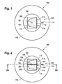
- Fig. 1 shows a top view of an example of a cartridge 100. Not all components are shown in this cartridge.
- the cartridge 100 has an axis of rotation or rotational axis 102. The location of the center of the cartridge 100 and the axis of rotation is indicated by the x labeled 102.
- the cartridge 100 has a central cavity 104. Within the central cavity 104 is a container 106 which has a fluid reservoir 108 that is filled with a fluid 110. One side of the container 106 is sealed with a pierceable seal 112. Within the central cavity 104 are a number of piercing elements 114.
- the container 106 is operable or configured for pivoting or rotating about the axis of rotation 102.
- Rotating the container 106 about the axis of rotation 102 causes the pierceable seal 112 to be pressed against a piercing element 114. When this happens the piercing element ruptures or pokes a hole in the pierceable seal 112 and allows the fluid 110 within the fluid reservoir 108 to escape and go into the central cavity 104.
- the cartridge 100, 200 can be rotated at relatively high rates about the axis of rotation 102 and this will drive the fluid 110 or 204 through the duct 116.
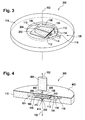
- the dashed line 206 in Fig. 2 shows the location of a cross-sectional view in Fig. 4 .
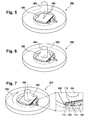
- Fig. 3 shows a perspective view of the same cartridge 200.
- Fig. 4 shows a perspective cross-sectional view of the cartridge 200 of Fig. 2 .
- Fig. 4 shows a cross-sectional view along the line 206.
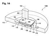
- the cartridge 200 can be seen as being made up of a carrier structure 118 and a cover 400.
- the container 106 has a first engaging surface 406 and the rotational actuator 404 has a second engaging surface 408.
- the second engaging surface 408 is a pin-like structure which digs into the cartridge and contacts the container 106.
- the hole 402 may be larger, in some examples it may be covered with a seal that may be removed by an operator before use. In other examples a seal may cover the hole 402 and then the second engaging surface 408 pushes through the seal and contacts the container 106.
- the container 106 has a small shaft 410 that extends a short way into the carrier structure 118. This may be used as a first frictional element 412 that contacts a second frictional element 414 of the carrier structure 118.
- the shaft 410 may have a press fit or may have some material or surface which makes friction when the container 106 tries to rotate about the axis 102.
- the space 416 between the container 106 and the carrier structure 118 may have a structure which is used to increase the rotational friction of the container 106. For instance small bits of these surfaces may be roughened or have a structure which hinders the free rotation of the container 106 relative to the cartridge 200.
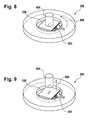
- the rotational actuator 404 holds the container 106 in a fixed location and the cartridge 200 is rotated clockwise along the rotation 700. This causes the piercing elements 114 to pierce the seal 112 of the fluid reservoir 202. This causes the fluid 204 to leak out and drain into the central cavity 104.
- Fig. 8 the cartridge 200 is rotated back in a counterclockwise direction 800 to put the position of the container 106 relative to the rest of the cartridge 200 back into its original starting position.
- FIG. 9 the rotational actuator 404 is withdrawn from the cartridge in the direction 900. As the rotational actuator 404 has moved away from the container the container 106 is no longer in a fixed location. A further rotation of the cartridge 200 will cause a rotation of the container 106 as well.
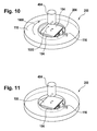
- FIG. 10 the rotational actuator 404 has been withdrawn. Then the cartridge 200 is rotated and the carrier structure 118 and the container 106 rotate together at the same rate. Arrows 1000 show the direction of rotation. This rotation forces the fluid 204 out of the pierced fluid reservoir 204 and into the central cavity 104. Further rotation forces the fluid 204 through the duct 116 into the fluidic structure of the cartridge 200.
- Fig. 11 shows the cartridge 200 where the fluid reservoir 204 and the central cavity 104 have both been emptied of fluid, it has all gone through the duct 116 into the fluidic structure of the cartridge 200.
- Fig. 12 shows an alternative design of a cartridge 1200.
- the design of the cartridge 1200 is similar to the design of the cartridge 100 shown in Fig. 1 , however in this example the container 106 has a pierceable seal 112 on opposite ends from each other located on surfaces 1202 and 1204. There is a piercing element 114 located near each pierceable seal 112.
- This particular design may have the advantage that the fluid reservoir 108 is opened at two ends. This may lead to better venting of the fluid reservoir 108 and/or faster draining of the fluid reservoir 108.
- Fig. 13 shows a cartridge 1300 similar to the cartridge 200 shown in Fig. 2 .
- Rotating the container 106 clockwise about the axis 102 relative to the carrier structure 118 causes the pierceable seal 112 of both the first fluid reservoir 108 and the second fluid reservoir 202 to be pierced at the same time.
- This may have the advantage that the first fluid 110 and the second fluid 204 can be mixed in the central cavity 104.
- the reservoirs may be opened one after the other causing one fluid to released first and the second fluid to be released in a subsequent step.
- Fig. 14 shows a cross-sectional view of the cartridge 1300 shown in Fig. 13 . This view is similar to the view before of cartridge 200.
- Fig. 15 shows a portion of a cartridge 1500.
- a small section of the carrier structure with a cavity 104' is shown.
- the cavity 104' is off of the axis of rotation 102.
- the container 106 is designed to slide within the cavity 104' but however rotate around the axis of rotation 102.
- the container 106 can be rotated either clockwise or counterclockwise around the axis of rotation 102.
- Fig. 16 the same portion 1500 of a cartridge showing the cavity 104' is shown again.
- the container 106 has been rotated clockwise relative to the cartridge 1500 around the axis of rotation 102 along the rotational direction 1600.
- the first fluid reservoir 108 has been opened because the piercing elements 114 have opened the pierceable seal 112.
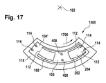
- Fig. 17 is similar to Fig. 16 except the container 106 has been rotated counterclockwise relative to the cartridge 1500 in the direction 1700 about the axis of rotation 102. In this example the second fluid reservoir 202 has been opened instead.
- Fig. 18 shows a portion of a cartridge 1800 showing the cavity 104'.
- the example shown in Fig. 18 is similar to that shown in Fig. 15 except the design of the container 106 is different.
- the pierceable seals 112 extend below the container 106.
- the pierceable seals 112 are pierced or torn by the piercing elements 114.
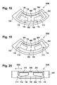
- Fig. 19 shows a further example of a portion of a cartridge 1900 showing cavity 104'.
- the example shown in Fig. 19 is similar to that shown in Fig. 15 except the pierceable seals 112 are on the corners of the container 106 instead of at the ends.
- the fluid reservoirs 108, 202 will still be opened by the rotation of the container 106 relative to the cartridge 1900 about the rotational axis.
- Fig. 20 shows a different example of a cartridge with a container 106 that is off axis.
- Fig. 20 shows a portion of a cartridge 2000 showing the cavity 104'. This is a cross-sectional view instead of a top view such as is shown in Figs. 15-19 .
- the container 106 can be rotated about the rotational axis and centrally moved relative to the cartridge 2000 in either of the directions labeled 2002. Moving the cartridge in either direction 2002 causes the piercing elements 114 to tear open the pierceable seals 112.
- Fig. 21 shows an example of a cartridge 2100 which incorporates the container 106 and cavity 104' structure 1500 that is illustrated in Fig. 15 .
- Fig. 21 shows a schematic view of two embodiments of the cartridge 2100 or test element.
- the test element 2100 comprises a housing 2115 having a substrate or carrier structure 118.
- the disc-shaped test element 2100 also typically contains a cover layer, which is not shown for the sake of clarity.
- the cover layer can fundamentally also carry fluidic structures, however, it will typically only have openings for delivering liquids or vent openings.
- a central hole or a shaft can be provided, around which the test element rotates.
- the rotation axis 102 in one embodiment is positioned inside the test element, or in another embodiment outside the test element.
- the housing 2115 of the test element 2100 has fluidic or micro fluidic as well as chromatographic structures.
- the sample liquid in particular whole blood, is delivered to the test element 2100 via the sample supply opening 2112.
- a sample analysis channel 2116 comprises the sample supply opening 2112 at its beginning and a measuring zone 2119 at its end in the flow direction.
- the liquid transport in the test element 2100 occurs by capillary forces and/or centrifugal forces.
- the flowing and/or the flow velocity of the liquid sample can be influenced by suitable selection of the fluidic structures of the sample analysis channel 2116.
- the dimensions of the channel sections 2117, 2118, 2121 is selected in such a manner that the occurrence of capillary forces is encouraged.
- the surfaces of the channel sections is hydrophilized.
- the further flowing or filling of the individual channel sections of the sample analysis channel 2116 can also only be made possible after the action of an external force, for example, in one embodiment a centrifugal force.
- a primary channel section 2118 can contain a reagent system reacting with the body fluid sample, of which at least one reagent in one embodiment is provided in dried or lyophilized form. It is also possible in another embodiment that at least one reagent is provided in liquid form, which is supplied to the test element 2100 by the fluid reservoirs 108 or 202 of the container 106.
- the channel section 2117 comprises a primary channel section 2118, a capillary stop 2120, and a secondary channel section 2 21.
- the capillary stop 2120 is implemented as a geometric valve or in another embodiment as a hydrophobic barrier.
- the secondary channel section 2121 adjoining the capillary stop 2120 guides a sample quantity measured off by the capillary stop 2120.
- the quantity flowing through the capillary stop 2120 is controlled by centrifugal forces using the rotational velocity of the test element 2100.
- the separation of red blood cells or other cellular sample components is started in the secondary channel section 2121.
- the reagents may be contained in a reagent system present in channel section 2118, which may be provided in dried form in one embodiment, are already dissolved upon entry of the sample liquid into the secondary channel section 2121.
- Components of the sample-reagent mixture are captured in the collection zones 2122 (plasma collection zone) and 2123 (erythrocyte collection zone), which are implemented as chambers.
- the measuring zone or measurement structure 2119 adjoining the collection zone 2122 in one embodiment includes a measuring chamber 2124, which in one embodiment contains a porous, absorbent matrix.
- a waste chamber 2125 is positioned after the measuring chamber 2124 in the flow direction.
- the reaction participants, sample components, and/or reagent components is disposed of in the waste chamber 2125 after flowing through the measuring chamber 2124.
- the waste chamber 2125 in one embodiment has a fluid connection to the measuring zone 2119 in such a manner that it receives the liquid which has flowed through the measuring zone 2119.
- Fig. 22 shows an example of an automatic analyzer.
- the automatic analyzer 2200 is adapted for receiving a cartridge 200.
- There is a cartridge spinner 2202 which is operable for rotating the cartridge 200 about the rotational axis 102.
- the cartridge spinner 2202 has a motor 2204 attached to a gripper 2206 which attaches to a portion of the cartridge 2208.
- the cartridge 200 is shown further as having a measurement or transparent structure 2210.
- the cartridge 200 can be rotated such that the measurement structure 2210 goes in front of a measurement system 2212 which can perform for example an optical measurement on the processed biological sample.
- the rotational actuator 404 as was shown previously is also shown in this Fig. It can be used to open one or more fluid reservoirs in the cartridge 200.
- the actuator 404, the cartridge spinner 2202, and the measurement system 2212 are shown as all being connected to a hardware interface 2216 of a controller 2214.
- the controller 2214 contains a processor 2218 in communication with the hardware interface 2216, electronic storage 2220, electronic memory 2222, and a network interface 2224.
- the electronic memory 2222 has a machine executable instructions 2230 which enable the processor 2218 to control the operation and function of the automatic analyzer 2200.
- the electronic storage 2220 is shown as containing a measurement 2232 that was acquired when instructions 2230 were executed by the processor 2218.
- the network interface 2224 enables the processor 2218 to send the measurement 2232 via network interface 2226 to a laboratory information system 2228.
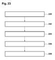
- Fig. 23 shows a flowchart which illustrates a method of operating the automatic analyzer 2200 of Fig. 22 .
- a biological sample is placed into a fluidic structure of the cartridge 200. This may be done manually or it may also be done if there is an automatic system for dispensing or pipetting the biological sample into the cartridge 200.
- a torque is applied to the at least one container using the rotational actuator 404 to overcome the friction between the cavity and the at least one container and rotate the at least one container relative the cartridge around the rotational axis 102 of the cartridge 200 to open the pierceable seal.
- the rotation of the at least one container relative to the cartridge causes the at least one piercing structure to open the seal by piercing the pierceable seal.
- the actuator 404 is separate from the motor assembly 2202.
- the actuator 404 can be used to hold the container stationary while the motor 2204 rotates the cartridge 200.
- the processor 2218 controls the rotational rate of the cartridge to process the biological sample into the processed biological sample using the fluidic structure.
- the processor controls the rotational rate of the cartridge to force the at least one fluid through the duct and through at least a portion of the fluidic structure. The friction between the cavity and the at least one container causes the at least one container to rotate around the rotational axis at the same rate as the cartridge.
- the measurement 2232 is performed using the measurement structure 2210 using the measurement system 2212.
- the steps 2302, 2304, 2306 may be performed multiple times and in different orders.
Landscapes
- Chemical & Material Sciences (AREA)
- Health & Medical Sciences (AREA)
- General Health & Medical Sciences (AREA)
- Analytical Chemistry (AREA)
- Dispersion Chemistry (AREA)
- Hematology (AREA)
- Clinical Laboratory Science (AREA)
- Chemical Kinetics & Catalysis (AREA)
- Life Sciences & Earth Sciences (AREA)
- Biochemistry (AREA)
- Physics & Mathematics (AREA)
- General Physics & Mathematics (AREA)
- Immunology (AREA)
- Pathology (AREA)
- Automatic Analysis And Handling Materials Therefor (AREA)
Priority Applications (7)
| Application Number | Priority Date | Filing Date | Title |
|---|---|---|---|
| EP14168042.1A EP2944965A1 (en) | 2014-05-13 | 2014-05-13 | Rotatable cartridge for measuring a property of a biological sample |
| CN201580023548.0A CN107076768B (zh) | 2014-05-13 | 2015-05-07 | 用于测量生物样品的性质的可旋转筒 |
| PCT/EP2015/060013 WO2015173097A1 (en) | 2014-05-13 | 2015-05-07 | Rotatable cartridge for measuring a property of a biological sample |
| KR1020167030033A KR101869184B1 (ko) | 2014-05-13 | 2015-05-07 | 생체 샘플의 특성을 측정하기 위한 회전가능한 카트리지 |
| EP15721222.6A EP3143412B1 (en) | 2014-05-13 | 2015-05-07 | Rotatable cartridge for measuring a property of a biological sample |
| JP2016562788A JP6549151B2 (ja) | 2014-05-13 | 2015-05-07 | 生体試料の特性を測定するための回転可能カートリッジ |
| US15/343,389 US9808801B2 (en) | 2014-05-13 | 2016-11-04 | Rotatable cartridge for measuring a property of a biological sample |
Applications Claiming Priority (1)
| Application Number | Priority Date | Filing Date | Title |
|---|---|---|---|
| EP14168042.1A EP2944965A1 (en) | 2014-05-13 | 2014-05-13 | Rotatable cartridge for measuring a property of a biological sample |
Publications (1)
| Publication Number | Publication Date |
|---|---|
| EP2944965A1 true EP2944965A1 (en) | 2015-11-18 |
Family
ID=50735885
Family Applications (2)
| Application Number | Title | Priority Date | Filing Date |
|---|---|---|---|
| EP14168042.1A Withdrawn EP2944965A1 (en) | 2014-05-13 | 2014-05-13 | Rotatable cartridge for measuring a property of a biological sample |
| EP15721222.6A Active EP3143412B1 (en) | 2014-05-13 | 2015-05-07 | Rotatable cartridge for measuring a property of a biological sample |
Family Applications After (1)
| Application Number | Title | Priority Date | Filing Date |
|---|---|---|---|
| EP15721222.6A Active EP3143412B1 (en) | 2014-05-13 | 2015-05-07 | Rotatable cartridge for measuring a property of a biological sample |
Country Status (6)
| Country | Link |
|---|---|
| US (1) | US9808801B2 (enExample) |
| EP (2) | EP2944965A1 (enExample) |
| JP (1) | JP6549151B2 (enExample) |
| KR (1) | KR101869184B1 (enExample) |
| CN (1) | CN107076768B (enExample) |
| WO (1) | WO2015173097A1 (enExample) |
Families Citing this family (13)
| Publication number | Priority date | Publication date | Assignee | Title |
|---|---|---|---|---|
| EP3173149A1 (en) | 2015-11-26 | 2017-05-31 | Roche Diagnostics GmbH | Determining a quantity of an analyte in a blood sample |
| WO2018043779A1 (ko) * | 2016-09-05 | 2018-03-08 | 주식회사 녹십자엠에스 | 당화혈색소 측정용 일체형 카세트 |
| US10137447B1 (en) * | 2017-05-17 | 2018-11-27 | Biotix, Inc. | Ergonomic fluid handling tubes |
| MX2021002160A (es) * | 2018-08-24 | 2021-04-28 | Zoetis Services Llc | Dispositivo de rotor microfluidico. |
| KR102599483B1 (ko) * | 2018-08-24 | 2023-11-08 | 조에티스 서비시즈 엘엘씨 | 마이크로 유체 회전자 디바이스 |
| US11094050B2 (en) | 2018-08-24 | 2021-08-17 | Zoetis Services Llc | Systems and methods for inspecting a microfluidic rotor device |
| EP3840884B1 (en) | 2018-08-24 | 2023-09-13 | Zoetis Services LLC | Methods for manufacturing a microfluidic rotor device |
| KR102600016B1 (ko) | 2018-08-24 | 2023-11-09 | 조에티스 서비시즈 엘엘씨 | 마이크로 유체 회전자 디바이스 |
| CN109991392B (zh) * | 2019-04-11 | 2021-07-30 | 中原工学院 | 一种用于土工试验液塑限联合测定的三瓣皿及测试方法 |
| CN118125056A (zh) * | 2019-05-03 | 2024-06-04 | 简·探针公司 | 用于分析系统的容器输送系统 |
| WO2023102427A1 (en) * | 2021-11-30 | 2023-06-08 | Gregor Diagnostics | Sample collection device and system |
| US20240377337A1 (en) * | 2023-05-11 | 2024-11-14 | Instrumentation Laboratory Company | Cartridges and uses thereof |
| DE102023208589A1 (de) * | 2023-09-06 | 2025-03-06 | Robert Bosch Gesellschaft mit beschränkter Haftung | Freisetzvorrichtung für ein Analysegerät zum Analysieren einer in einer Kartusche enthaltene Probe, Analysegerät und Verfahren zum Betreiben eines Analysegerätes |
Citations (7)
| Publication number | Priority date | Publication date | Assignee | Title |
|---|---|---|---|---|
| US20040116686A1 (en) * | 2001-05-25 | 2004-06-17 | Teruhisa Akashi | Apparatus for purifying nucleic acid and method of purifying nucleic acid |
| US20070065346A1 (en) * | 2005-09-19 | 2007-03-22 | Henry Lauren R | Micro-fluidic device with neutralization and neutralization methods |
| US8114351B2 (en) | 2007-11-24 | 2012-02-14 | Roche Diagnostics Operations, Inc. | Analysis system and method for the analysis of a body fluid sample for an analyte contained therein |
| US20120291538A1 (en) * | 2011-05-18 | 2012-11-22 | 3M Innovative Properties Company | Systems and methods for volumetric metering on a sample processing device |
| US8470588B2 (en) | 2006-09-27 | 2013-06-25 | Roche Diagnostics Operations, Inc. | Rotatable test element |
| US20130344617A1 (en) * | 2011-03-15 | 2013-12-26 | Carclo Technical Plastics Lmited | Sample metering |
| WO2014041364A1 (en) * | 2012-09-14 | 2014-03-20 | Carclo Technical Plastics Limited | Sample metering device |
Family Cites Families (10)
| Publication number | Priority date | Publication date | Assignee | Title |
|---|---|---|---|---|
| US4812294A (en) * | 1986-02-28 | 1989-03-14 | Automated Diagnostic Systems, Inc. | Specimen processing system |
| EP0533801B1 (en) * | 1990-06-15 | 1994-08-10 | Chiron Corporation | Self-contained assay assembly and apparatus |
| US6309875B1 (en) * | 2000-02-29 | 2001-10-30 | Agilent Technologies, Inc. | Apparatus for biomolecular array hybridization facilitated by agitation during centrifuging |
| US20040131500A1 (en) * | 2002-01-18 | 2004-07-08 | Chow Herbert S. | Device and method for evaluating platelets |
| US20030219890A1 (en) * | 2002-05-21 | 2003-11-27 | Gordon Gary B. | Probe array bio-analysis by centrifuging shallow reaction cell |
| US20050169804A1 (en) * | 2004-02-04 | 2005-08-04 | Hach Company | User-configurable analytical rotor system |
| JP2006308366A (ja) * | 2005-04-27 | 2006-11-09 | Hitachi High-Technologies Corp | 化学分析装置及び化学分析カートリッジ |
| JP4901333B2 (ja) * | 2006-06-30 | 2012-03-21 | ローム株式会社 | マイクロチップ検査装置 |
| KR20080107212A (ko) * | 2007-06-05 | 2008-12-10 | 삼성전자주식회사 | 유체 컨테이너를 구비한 미세유동 장치 |
| US20110085950A1 (en) * | 2009-10-08 | 2011-04-14 | Samsung Electronics Co., Ltd. | Centrifugal force based microfluidic system and bio cartridge for the microfluidic system |
-
2014
- 2014-05-13 EP EP14168042.1A patent/EP2944965A1/en not_active Withdrawn
-
2015
- 2015-05-07 WO PCT/EP2015/060013 patent/WO2015173097A1/en not_active Ceased
- 2015-05-07 EP EP15721222.6A patent/EP3143412B1/en active Active
- 2015-05-07 JP JP2016562788A patent/JP6549151B2/ja active Active
- 2015-05-07 CN CN201580023548.0A patent/CN107076768B/zh active Active
- 2015-05-07 KR KR1020167030033A patent/KR101869184B1/ko active Active
-
2016
- 2016-11-04 US US15/343,389 patent/US9808801B2/en active Active
Patent Citations (7)
| Publication number | Priority date | Publication date | Assignee | Title |
|---|---|---|---|---|
| US20040116686A1 (en) * | 2001-05-25 | 2004-06-17 | Teruhisa Akashi | Apparatus for purifying nucleic acid and method of purifying nucleic acid |
| US20070065346A1 (en) * | 2005-09-19 | 2007-03-22 | Henry Lauren R | Micro-fluidic device with neutralization and neutralization methods |
| US8470588B2 (en) | 2006-09-27 | 2013-06-25 | Roche Diagnostics Operations, Inc. | Rotatable test element |
| US8114351B2 (en) | 2007-11-24 | 2012-02-14 | Roche Diagnostics Operations, Inc. | Analysis system and method for the analysis of a body fluid sample for an analyte contained therein |
| US20130344617A1 (en) * | 2011-03-15 | 2013-12-26 | Carclo Technical Plastics Lmited | Sample metering |
| US20120291538A1 (en) * | 2011-05-18 | 2012-11-22 | 3M Innovative Properties Company | Systems and methods for volumetric metering on a sample processing device |
| WO2014041364A1 (en) * | 2012-09-14 | 2014-03-20 | Carclo Technical Plastics Limited | Sample metering device |
Non-Patent Citations (2)
| Title |
|---|
| KIM, TAE-HYEONG ET AL.: "Flow-enhanced electrochemical immunosensors on centrifugal microfluidic platforms", LAB ON A CHIP, vol. 13.18, 2013, pages 3747 - 3754 |
| MARTINEZ-DUARTE, RODRIGO ET AL.: "The integration of 3D carbon-electrode dielectrophoresis on a CD-like centrifugal microfluidic platform", LAB ON A CHIP, vol. 10.8, 2010, pages 1030 - 1043 |
Also Published As
| Publication number | Publication date |
|---|---|
| CN107076768B (zh) | 2018-11-30 |
| WO2015173097A1 (en) | 2015-11-19 |
| US9808801B2 (en) | 2017-11-07 |
| CN107076768A (zh) | 2017-08-18 |
| JP2017516086A (ja) | 2017-06-15 |
| US20170050185A1 (en) | 2017-02-23 |
| EP3143412A1 (en) | 2017-03-22 |
| KR101869184B1 (ko) | 2018-06-19 |
| EP3143412B1 (en) | 2019-12-18 |
| KR20160137633A (ko) | 2016-11-30 |
| JP6549151B2 (ja) | 2019-07-24 |
Similar Documents
| Publication | Publication Date | Title |
|---|---|---|
| US9808801B2 (en) | Rotatable cartridge for measuring a property of a biological sample | |
| US11406979B2 (en) | Rotatable cartridge for processing and analyzing a biological sample and dispensing method therewith | |
| US10016758B2 (en) | Rotatable cartridge for analyzing a biological sample | |
| US10307757B2 (en) | Rotatable cartridge with a metering chamber for analyzing a biological sample | |
| EP2957890A1 (en) | Cartridge with a rotatable lid |
Legal Events
| Date | Code | Title | Description |
|---|---|---|---|
| PUAI | Public reference made under article 153(3) epc to a published international application that has entered the european phase |
Free format text: ORIGINAL CODE: 0009012 |
|
| AK | Designated contracting states |
Kind code of ref document: A1 Designated state(s): AL AT BE BG CH CY CZ DE DK EE ES FI FR GB GR HR HU IE IS IT LI LT LU LV MC MK MT NL NO PL PT RO RS SE SI SK SM TR |
|
| AX | Request for extension of the european patent |
Extension state: BA ME |
|
| STAA | Information on the status of an ep patent application or granted ep patent |
Free format text: STATUS: THE APPLICATION IS DEEMED TO BE WITHDRAWN |
|
| 18D | Application deemed to be withdrawn |
Effective date: 20160519 |