EP2944436B1 - Support frame with lockable rattle-free support elements - Google Patents
Support frame with lockable rattle-free support elements Download PDFInfo
- Publication number
- EP2944436B1 EP2944436B1 EP15166717.7A EP15166717A EP2944436B1 EP 2944436 B1 EP2944436 B1 EP 2944436B1 EP 15166717 A EP15166717 A EP 15166717A EP 2944436 B1 EP2944436 B1 EP 2944436B1
- Authority
- EP
- European Patent Office
- Prior art keywords
- support
- clamping
- support element
- support frame
- locking
- Prior art date
- Legal status (The legal status is an assumption and is not a legal conclusion. Google has not performed a legal analysis and makes no representation as to the accuracy of the status listed.)
- Active
Links
Images


Classifications
-
- B—PERFORMING OPERATIONS; TRANSPORTING
- B25—HAND TOOLS; PORTABLE POWER-DRIVEN TOOLS; MANIPULATORS
- B25H—WORKSHOP EQUIPMENT, e.g. FOR MARKING-OUT WORK; STORAGE MEANS FOR WORKSHOPS
- B25H1/00—Work benches; Portable stands or supports for positioning portable tools or work to be operated on thereby
- B25H1/02—Work benches; Portable stands or supports for positioning portable tools or work to be operated on thereby of table type
- B25H1/04—Work benches; Portable stands or supports for positioning portable tools or work to be operated on thereby of table type portable
-
- B—PERFORMING OPERATIONS; TRANSPORTING
- B25—HAND TOOLS; PORTABLE POWER-DRIVEN TOOLS; MANIPULATORS
- B25H—WORKSHOP EQUIPMENT, e.g. FOR MARKING-OUT WORK; STORAGE MEANS FOR WORKSHOPS
- B25H1/00—Work benches; Portable stands or supports for positioning portable tools or work to be operated on thereby
- B25H1/14—Work benches; Portable stands or supports for positioning portable tools or work to be operated on thereby with provision for adjusting the bench top
- B25H1/16—Work benches; Portable stands or supports for positioning portable tools or work to be operated on thereby with provision for adjusting the bench top in height
-
- B—PERFORMING OPERATIONS; TRANSPORTING
- B25—HAND TOOLS; PORTABLE POWER-DRIVEN TOOLS; MANIPULATORS
- B25H—WORKSHOP EQUIPMENT, e.g. FOR MARKING-OUT WORK; STORAGE MEANS FOR WORKSHOPS
- B25H1/00—Work benches; Portable stands or supports for positioning portable tools or work to be operated on thereby
- B25H1/14—Work benches; Portable stands or supports for positioning portable tools or work to be operated on thereby with provision for adjusting the bench top
- B25H1/18—Work benches; Portable stands or supports for positioning portable tools or work to be operated on thereby with provision for adjusting the bench top in inclination
Definitions
- the invention relates to a support frame, in particular workbench or workpiece support with a first support member, a pivotally hinged thereto second support member and the two support elements associated retaining elements which fix the two support members in a locking position in a first pivot position and in a release position, a pivoting of the support elements in allow a second pivot position.
- a support frame with two support elements, one of which extends in a use position substantially in the horizontal direction and a second support member extends substantially in the vertical direction describes the WO 00/53375 A1 .
- a jaw assembly At the upwardly facing end of the substantially vertically extending support member sits a jaw assembly.
- the two support elements are held by means of holding means in a position of use, which corresponds to a first pivot position of the two support members to each other. If the retaining means are brought from a locking position into a release position, then the support elements can be pivoted into a non-use position.
- Workbenches, workpiece supports have two mutually pivotable support members which are fixed in a position of use by means of holding means in a first pivot position also show the US 2005/0011421 A1 .
- CH 347966 and DE 197 35 336 A1 show the US 2005/0011421 A1 .
- the invention has for its object to further develop the generic support frame nutzsvorteilhaft.
- the holding means have a clamping element.
- the clamping element can be brought from a locking position into a release position.
- the clamping element is in the position of use of the support frame to a clamping edge by clamping.
- the clamping element may be associated with the first support element.
- the clamping flank can be assigned to the second support element.
- the clamping element may be formed by a pivotable clamping lever.
- the clamping element can be movably arranged in a cavity of the support element.
- the support element may be a pipe, in particular a square pipe. In the cavity of the tube, the clamping element may be located. It can be arranged pivotably about a pivot axis in the pipe.
- the pipe wall may have a window, which may have a slot shape.
- a head of the clamping element protrudes to the outside.
- the clamping edge which is formed in particular by a peripheral edge of a flange plate which is fixedly connected to the second support member.
- This clamping edge extends at an acute angle to the pivot plane of the clamping element, wherein the angle is less than the maximum self-locking angle, so that the clamping element rests in the clamping position while exerting a torque about the pivot axis of the two support elements on the clamping edge.
- a portion of the head of the clamping element is supported on the clamping edge and a portion of the head of the clamping element opposite this section at an edge of the Slit through which the clamping element protrudes from the cavity of the support element to the outside.
- the clamping element is displaceable by a displacement of an actuating member of the locking position corresponding to the clamping position in the release position.
- the actuator may have a window and be displaceable within the tube cavity of the support element.
- the lever arm of the clamping element passes through the window of the actuator.
- the latter has a pressure flank and a lifting flank.
- the actuator may be loaded by a spring, in particular a tension spring in the direction of the clamping position. The pressure edge of the window acts on the clamping element in the direction of its clamping position.
- the actuating member If the actuating member is displaced against the restoring force of the spring, the lifting flank lying opposite the pressure flank, after passing through a movement play, engages on the lever arm of the clamping element in order to bring the clamping element into the release position.
- the head of the clamping element which in particular has an oblique face, in the opening plane of the window of the support element, in front of which displaces a broad side surface of the flange during pivoting of the two support elements, on which the end face of the clamping element can be supported, if the actuator due to the force of the spring acting on it shifted back again, so that the pressure edge acts on the clamping element.
- the holding elements on fixed stops may have a stop, in particular a pin-shaped stop, which is associated with the first support element. In the position of use can abut against this stop a counter-stop of the other support element.
- the counter-stop is formed by a stop table of the flange plate.
- the fixed stops can absorb the clamping force in the clamping position, which transmits the clamping element on the clamping edge.
- a locking pin provided, which rests in the locking position in a latching niche.
- the latching pin may be assigned to the first support element and the latching niche to the second support element, in particular the flange plate.
- the locking pin can be firmly seated on the actuating member, so that it can be brought together with the clamping element in a displacement of the actuating member of the locking position in a release position.
- the locking pin can slide on pivoting of the two support elements on a guide flank of a guide slot along.
- the guide flank extends on a circular arc line about the pivot axis about which the two support elements are pivotable.
- the axis about which the two support elements are pivotable extends transversely to the plane of extent of the flange plate. It extends transversely to the surface extension of two mutually parallel walls of the tubular support element.
- the pivot axis about which the clamping element is pivotable runs parallel to the surface plane of extension of these two tube walls.
- the pivoting plane of the clamping element extends in particular transversely to the surface extension of two transverse to the first tube walls second tube walls of a rectangular cross-section having tube, which forms the first support member.
- the second support element extends in the position of use approximately in a horizontal plane.
- the first support member has at its lower end a first foot. Adjacent to the lower end, the second support element is articulated on the first support element. The free end of the second support element forms a second foot.
- There are two pairs of legs are provided, each having a first support member and a second support member, so that the support frame has a total of four feet.
- the two support element pairs are connected to each other via connecting elements.
- the connecting elements may be rigid traverses, each rigidly interconnecting two first support elements and two second support elements.
- first support member may be a support element.
- the further support element can be assigned to be telescopically associated with the first support element.
- a carrier attached to the end of the further support element can thus be brought to different working heights.
- the carrier carries in particular in a horizontal plane to each other displaceable jaws that form a workbench surface.
- a tension member which may be a pull rod, engages the actuator.
- a Ceiende the tension element is located within the further support element, which has a longitudinal slot through which an end portion of the tension member protrudes from the tubular further support member. There, the tension element is connected to a handle.
- the handle may be a transverse bar that extends parallel to the connecting elements and on which a user's hand may engage to exert a pull on the pulling element with which the actuating element can be displaced against the restoring force of the spring, to bring the clamping element in the release position to.
- the latching pin is also lifted out of the latching niche so that the second support element, which is a foot element, can be pivoted from the use position to a non-use position.
- the invention also relates to a development of the locking of the support element in the obliquely upwardly projecting support element.
- a support frame with an erectable on a base frame which has at least one obliquely in a vertical plane upwardly projecting elongated support member in the telescopically inserted an elongated support member, at the upper end of a support is fixed, wherein the support element can be fixed by means engaging in detent openings form-fitting retaining elements in different heights of the wearer on the support element.
- the form-fitting retaining elements of locking pins or of the threaded shafts of screws are formed, which in one of a plurality of openings of the support element intervention. The screw or the locking pin must be displaced out of the opening, so that the latching connection is canceled for the purpose of vertical displacement of the support element in the support element.
- the invention has for its object to further develop the support frame nutzsvorteilhaft.
- this positive engagement holding element can be brought into and out of engagement with the latching opening by a pivoting movement of the support element relative to the support element.
- the positive locking element can hook-like engage in the opening. This has the consequence that the support element must first be moved slightly vertically upwards before the pivoting movement, so that the hook engagement is released. In this respect, the locking connection is canceled by a lifting / pivoting movement.
- the support member may be a rectangular tube, in which a designed as a rectangular tube support element inserted.
- the opening into which the form-fitting retaining element engages may be associated with a narrow side wall of the rectangular tube. Accordingly, the form-fitting retaining element is associated with a narrow side wall of the support element having a rectangular outline.
- the two facing away from each other narrow sides of the support element have a distance from each other, which is greater than the distance between the two outwardly facing narrow side planes of the support element.
- the support member can move so far within the tube cavity of the support member that the positive locking member can emerge from the detent opening.
- the form-fitting retaining element is preferably assigned to the narrow side of the support element facing downwards in the inclined state.
- a support cam which projects beyond the broad side surface of the support element, which lies opposite the latching openings.
- the form-fitting retaining element is arranged directly next to the opening edge of the pipe opening of the holding element.
- the the support cam opposite side wall of the support element is supported on the edge of the pipe opening of the support element. Due to the inclined position of the support element and the support element, a torque builds up due to gravity. As a result of this gravitational torque, the support cam is supported on the inner wall of the support element.
- the projection of the support cam relative to its associated side wall of the support element corresponds approximately to the pivoting movement of the support element in the region of the form-locking element, so that in the latched state, the openings having side wall of the support element is substantially parallel and preferably in planar contact with the inner side wall of the support element.
- the positive locking member may be formed by the head of a countersunk screw.
- the countersunk screw is screwed into a screw-in opening of the support element.
- the diameter of the screw hole is only slightly larger than the diameter of the threaded shaft of the countersunk screw.
- the countersunk head thus protrudes beyond the inner wall of the support element and forms an oblique latching step.
- a nut is screwed onto the shaft of the Senckopfschraube.
- the FIG. 1 shows a chuck table with a support frame, which forms two mutually parallel first support elements 1, which are connected to each other with rigid connecting elements 35, 38.
- the first two Support elements 1 are formed by square tubes and carry at their lower end respectively feet 36.
- stuck support members 27 forming square tubes, which are arranged to adjust the height of a fastened to the end of the support element 27 carrier 28 in the first support member telescopically.
- the altitude can be fixed by means of locking elements.
- a spring element 34 supports the lifting of the carrier 28.
- the carrier 28 is a clamping jaw carrier, on whose upwardly facing side two clamping jaws 29, 30 are arranged, which are mutually displaceable by means of a spindle drive.
- the tops of the jaws 29, 30 form work surfaces.
- the extension direction of the longitudinal slots 47, 48 is transverse to an adjustment in which adjustment the two jaws 29, 30 can be displaced towards each other by means of cranks and a spindle drive.
- the clamping jaw 29 is firmly connected to the carrier 28 both in the vertical direction and in the horizontal direction.
- the clamping jaw 30 is connected in the horizontal direction fixed to the carrier 28, but displaceable by pressing the spindle drive relative to the fixed jaw 29. As a result, the distance between the longitudinal slots 48 of the clamping jaw 30 moves to the longitudinal slots 47 of the clamping jaw 29th
- a plurality of longitudinal slots 47, 48 adjacent one another in a direction transverse to the adjustment direction and a plurality of longitudinal slots 47, 48 lying adjacent one another in the adjustment direction are provided.
- the longitudinal slots formed by oblong holes extend transversely to the adjustment and serve for the attachment of tool receiving plates.
- Such a tool receiving plate can be fastened, for example, with four screws on the work surface, wherein two screws in two longitudinal slots 47 of the clamping jaw 29 and two further screws in two longitudinal slots 48 of the clamping jaw 30 engage.
- An electric motor or an electric motor driven Tool which is attached to the screwed with the clamping jaws mounting plate, is then located between the two jaws 29, 30th
- a second support element 2 is pivotally arranged on the first support elements.
- the free end of the second support element 2 also carries a foot 37.
- the two second support elements 2 are connected by means of the connecting elements 35 rigidly together.
- the pivot axis 3, to which the second support member 2 of the in the FIG. 1 shown use position in a non-use position, not shown, is pivotable, is formed by a screw which passes through holes formed by two mutually parallel walls of the first support member 1 forming square tube.
- the connecting element 35 lies approximately in the pivot axis.
- the flange plate 11 On the second support member 2, a flange plate 11 is attached.
- the flange plate 11 has a broad side surface which bears against a broad side surface of the square tube 1.
- the broad side surface of the square tube 1 has a first slot-shaped window 13 and a second slot-shaped window 14.
- the head of a clamping element 6 protrudes through the first slot-shaped window 13.
- the clamping element 6 is a clamping lever, which is mounted pivotably about a pivot axis 16 on the first support element 1.
- the clamping lever 6 can be from a locking position, in the FIG. 9 is shown and in which the head of the clamping lever 6 protrudes from the window 13 on the broad side surface of the first support member 1, move in a release position, in the FIG. 10 is shown.
- the head of the clamping lever 6 is completely within the window 13.
- the obliquely cut end face 15 of the head of the clamping lever 6 lies here within the window 13 such that the flange plate 11 can slide over the slot-shaped window 13.
- a short end 17 of the clamping lever 6 protrudes from the second window 14 opposite the first window 13.
- the first support element 1 forms a square tube, with two first mutually parallel side walls, to which the pivot axis 3 extends in the transverse direction.
- Two second broad side surfaces of the first support element extend transversely to the first broad side surfaces. Transverse to the second broad side surfaces extends the pivot axis 16 about which the clamping element is pivotable.
- the two pivot axes 3, 16 are spaced apart in the extension direction of the first support element.
- the actuator 18 has two laterally projecting wings 23, 23 ', which can rest with play on the inner surfaces of the two shorter side surfaces of the support element 1.
- One of these shorter side walls carries the pivot axis 16 of the clamping element 6.
- the actuator 18 carries a locking pin 4, which protrudes from the window 14 from the cavity of the first support member.
- the locking pin 4 is in a detent niche 5 of the flange 11.
- At the detent niche 5 is followed by a circular arc around the pivot axis 3 extending guide edge 12 ', which is formed by the peripheral edge of an arcuate guide slot 12 is.
- the pivot axis 3 passes through an abutment 39, which is located within the first support element 1. It ties the abutment 39 to the first support element. At the abutment 39, one end of a tension spring 25 is attached. The other end of the tension spring 25 is attached to the actuator 18. The tension spring 25 acted upon the actuator 18 such that the locking pin 4 is held in the latching niche 5. On the actuating member 18 engages a pull rod 26 which extends through the tube cavity of the first support member 1 through into the tube cavity of the support member 27, where an actuating end of the tie rod 26 through a slot 32 which extends in the extension direction of the support member 27, from the Cavity of the support member 27 protrudes.
- a handle 31 is fixed, which extends parallel to the connecting element 38. If the handle 31 is pulled upwards, then the actuating member 18 also displaces upward, so that the latching pin 4 emerges from the latching niche 5. This is done against the restoring force of the spring 25.
- the abutment 39 has a lateral recess in which a bushing 41 engages.
- the bushing 41 passes through an opening of the wall of the support element 1 and an opening of the flange plate 11. An end edge of the bushing 41 is supported on the outside of the second support member 2 from.
- the opening 42 of the wall of the first support element 1 essentially surrounds the outer wall of the bushing 41, through which the pivot axis 3 extends.
- a shim 43 which holds the flange plate 11 slightly spaced from the outer wall of the support member 1.
- the wing 23 of the actuator 18 has a window 21 which is penetrated by movement play up and down from the clamping element 6. If the actuator 18 takes its locking position shown in the drawings, in which the locking pin 4 is located in the detent niche 5, the long lever arm of the clamping element 6 in the immediate vicinity of the slot 13 on the inside of the support element 1 of a pressure edge 19 of the window 21 down acted upon by the tensile force of the tension spring 25. If the actuating member 18 is displaced upward, then a clearance first takes place until the lifting flank 20 strikes the clamping element 6. At another Upward displacement of the actuator 18, the clamping member 6 about the pivot axis 16 of the in FIG. 9 illustrated locking position in the in FIG. 10 shifted released release position.
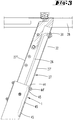
- FIGS. 4 and 7 show the holding elements, namely the locking pin 4, the latching niche 5, the clamping element 6, the clamping edge 7 and the stop 9 with counter-stop 10 in the locked position.
- the locking pin 4 is a tolerance-induced movement in the detent niche 5 a.
- the outer wall of a core surrounding the detent pin sleeve is spaced a slight distance from the wall 8 of the detent niche 5.
- the counter-stop 10 is in touching contact with the stop 9.
- the plane of movement B within which the clamping element 6 can pivotally displace forms a lying below the self-locking flat angle to the clamping edge 7, which is formed by a substantially rectilinear edge of the flange plate 11.
- the head of the clamping element 6 projecting out of the window 13 exerts a clamping force or a clamping force on the clamping flank 7.
- the torque introduced thereby into the flange plate 11 is transmitted to the stop 9.
- the head of the clamping element 6 is supported by a first section on the clamping edge 7. A portion of the clamping element 6 lying opposite this section is supported on a peripheral edge 13 'of the slot 13.
- the actuator 18 is brought by train on the handle 31 in an upwardly displaced position.
- the latching pin 4 is lifted out of the latching niche 5 into a release position.
- the clamping lever 6 is also in the in FIG. 10 shifted released release position.
- the second support element with respect to the representations in the FIGS. 7 and 8th be pivoted counterclockwise relative to the first support member 1.
- the end face 15 of the clamping lever 6 slides along a broad side surface of the flange plate 11 along.
- the locking pin 4 runs along the guide flank 12 'along. The actuator 18 can thus not be moved to its lowered position.
- a recess 40 into which the locking pin 5 can enter in a storage position of the second support member 2.
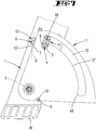
- first support element is located on the downwardly facing narrow side of the support member 1, a form-locking element 44.
- a form-locking element 44 is formed by the head of a countersunk screw.
- the threaded shaft of the countersunk screw passes through an opening of the narrow side wall of the first support element from the inside to the outside.
- the diameter of the opening is only slightly larger than the diameter of the threaded shank of the countersunk screw, so that the thread-fitting approach of the frusto-conical head 44 is supported on the inside edge of the opening.
- the majority of the head 44 thus projects into the square opening of the support element 1.
- On the outwardly projecting thread a nut 44 'is screwed.
- the clear opening between the two narrow side walls of the first support element is sufficiently larger than the distance between the outer sides of the facing away narrow sides 27 ', 27 "of the support member 27 so that the support member 27 can be brought by a pivoting movement into and out of engagement of a positive engagement with the form-locking means 44
- the countersunk head 44 engages in one of a plurality of openings 45 of the narrow side wall 27.
- An edge of the opening 45 lies on an upwardly pointing portion of the conical jacket wall portion of the countersunk head 44.
- the hook engagement can be canceled by a slight lifting movement
- the screw head 44 passes through the pivoting movement out of the opening 45, so that the support member 27 can be moved in its direction of extension. Along with this changes the altitude of the carrier 28.
- the support member 27 are slightly raised and then pivoted counterclockwise. It can then be moved in a slightly pivoted position both upwards, and downwards. By a pivoting movement in the clockwise direction, the positive locking member 44 can engage in another opening 45 of the support element.
- the spring 34 which has a rectangular cross-section, absorbs part of the weight of the carrier 28 and of the clamping jaws.
- the upper end of the helical spring 34 has a smaller cross-section than the lower portion of the spring element and stuck on a rectangular extension on the underside of the support element 27th
- a support frame which is characterized in that the holding elements 6, 7; 4, 5; 9, 10 have a one of the two support elements 1 associated clamping element 6 which abuts in the locking position on a clamping element 7 associated with the other support member 2 clamping edge.
- a support frame which is characterized in that the clamping element 6 is a lever pivotable about a pivot axis 16 which is arranged in particular in the interior of a hollow body formed by the first support member 1 and has a protruding through a window 13 from the cavity head, in a Swivel plane B is displaced, which extends at an acute angle to the clamping edge 7, which is formed in particular by a fixedly connected to the second support member 2 flange plate 11.
- a support frame which is characterized in that the holding means 6,7; 4, 5; 9, 10 in the first pivot position contacting contiguous fixed stops 9, 10 form, in particular the first support member 1, a stop 9 and the second support member 2 is associated with a counter-stop 10.
- a support frame which is characterized in that the holding elements 6, 7; 4, 5; 9, 10 have a latching pin 4, which rests in the locking position in a latching niche 5 and in particular together with the clamping element 6 is displaceable from the locking position to the release position.
- a support frame which is characterized in that the first support member 1 is a tubular body, with an arranged within the tube actuator 18 which is displaceable in particular against the force of a spring 25 in the extension direction of the first support member 1 and carrier of the locking pin 4 and in its displacement from the locking position into the release position, the clamping element 6 is displaced into the release position, wherein it is provided in particular that one arm of the clamping element 6 projects through a window 21 of the actuating member 18, which window 21 forms a lifting flank 20 and a pressure flank 19.
- a support frame which is characterized in that the clamping element 6 has an end face 15 which is supported during pivoting from the first pivot position to the second pivot position on a broad side surface of the flange 11, the pivoting of the two support members 1, 2 on the window 13th of the support element 1 pivots over.
- a support frame which is characterized in that the window 13 is a slot with a peripheral edge 13 'at which peripheral edge 13', the clamping element 6 is supported with a first portion, wherein a second portion pointing away from the first portion on the clamping edge 7 is supported.
- a support frame which is characterized in that the locking pin 4 rests with tolerance-related motion play in the latching niche 5, to which a guide edge 12 'connects, at which the brought into a release position locking pin 4 slides during pivoting of the support elements 1, 2 along.
- a support frame which is characterized in that the first support member 1 at its corresponding in one of the first pivot position use position the support frame downwardly facing end forms a first leg 36 that the second support member 2 is articulated in the immediate vicinity of the first foot 36 on the first support member 1 and forms a second foot 37 with its free end.
- a support frame which is characterized in that a support element pair 1, 2 four feet 36, 37 forming with connecting elements 35, 38 is connected to each other and the first support member 1 with its in the position of use upwardly facing end a support 28, in particular a clamping jaws 29th 30 carrying carrier 28 carries, and / or that in the clamping jaws 29, 30 transverse to an adjustment of the two clamping jaws 29, 30 extending longitudinal slots 47, 48 are provided.
- a support frame which is characterized in that in the cavity of the first support member 1, a support member 27 is telescopically arranged, in which an actuating end of an actuating member 18 acting on the tension element 26 is arranged, in particular provided that the support member 27 has a slot 32 through which an operating end of the pulling element 26 connected to a handle 31 protrudes.
- a support frame which is characterized in that the positive locking holding element 27 can be brought into and out of engagement with a latching opening 45 by a pivoting movement of the support element 27 relative to the support element 1.
- a support frame which is characterized in that the form-fitting retaining element 44 is formed by the head of a countersunk screw, which head 44 forms with its cone portion a hook, so that the positive locking member by a lifting / pivoting movement of the support member into and out of engagement in a detent opening 45 is brought.
- a support frame characterized in that the form-fitting engagement member 44 is disposed immediately adjacent to the edge of an opening of a pipe forming the support member 1 and fixed to the inner wall of the pipe.
- a support frame which is characterized in that on the plug-in support element 1 end of the support member, a support cam 46 is arranged, which protrudes from the wall of the support member 27 and is supported on the inside of the obliquely upwardly facing wall of the support element (1).
Description
Die Erfindung betrifft ein Tragegestell, insbesondere Werktisch oder Werkstückstütze mit einem ersten Tragelement, einem schwenkbar daran angelenkten zweiten Tragelement und den beiden Tragelementen zugeordnete Halteelemente, die in einer Verriegelungsstellung die beiden Tragelemente in einer ersten Schwenkstellung fixieren und die in einer Freigabestellung ein Verschwenken der Tragelemente in eine zweite Schwenkstellung erlauben.The invention relates to a support frame, in particular workbench or workpiece support with a first support member, a pivotally hinged thereto second support member and the two support elements associated retaining elements which fix the two support members in a locking position in a first pivot position and in a release position, a pivoting of the support elements in allow a second pivot position.
Ein Tragegestell mit zwei Tragelementen, von denen eins in einer Gebrauchsstellung im Wesentlichen sich in Horizontalrichtung erstreckt und ein zweites Tragelement sich im Wesentlichen in Vertikalrichtung erstreckt, beschreibt die
Werktische, Werkstückstützen die zwei gegeneinander verschwenkbare Tragelemente aufweisen, die in eine Gebrauchsstellung mittels Haltemitteln in einer ersten Schwenkstellung fixiert sind zeigen darüber hinaus auch die
Bei Tragegestellen, insbesondere Spanntischen, Werktischen oder Werkstückstützen, bei den die Haltemittel einen Rastzapfen aufweisen, der in der Verriegelungsstellung in einer Rastnische liegt, kommt es toleranzbedingt zu einem Spiel zwischen dem Rastzapfen oder einem anderen Halteelement und einem Gegenhalteelement, beispielsweise den beiden Wandungen der Rastnische, zwischen denen der Rastzapfen liegt. Diese toleranzbedingte Spiel führt zu Klappergeräuschen bei einem auf die Tragelemente ausgeübten Lastwechsel.In carrying racks, in particular clamping tables, workbenches or workpiece supports, in which the holding means have a locking pin, which is in the locking position in a detent niche, it comes to tolerances due to a game between the locking pin or another holding element and a counter holding element, for example, the two walls of the detent niche . between which lies the locking pin. This tolerance-related game leads to rattling noises in a load change exerted on the support elements.
Der Erfindung liegt die Aufgabe zugrunde, das gattungsgemäße Tragegestell gebrauchsvorteilhaft weiterzubilden.The invention has for its object to further develop the generic support frame nutzsvorteilhaft.
Gelöst wird die Aufgabe durch die in den Ansprüchen angegebene Erfindung.The object is achieved by the invention specified in the claims.
Zunächst und im Wesentlichen ist vorgesehen, dass die Haltemittel ein Klemmelement aufweisen. Das Klemmelement kann von einer Verriegelungsstellung in eine Freigabestellung gebracht werden. Das Klemmelement liegt in der Gebrauchsstellung des Tragegestells an einer Klemmflanke klemmend an. Das Klemmelement kann dem ersten Tragelement zugeordnet sein. Die Klemmflanke kann dem zweiten Tragelement zugeordnet sein. Das Klemmelement kann von einem schwenkbaren Klemmhebel ausgebildet sein. Das Klemmelement kann beweglich in einer Höhlung des Tragelementes angeordnet sein. Bei dem Tragelement kann es sich um ein Rohr, insbesondere um ein Vierkantrohr handeln. In der Höhlung des Rohres kann sich das Klemmelement befinden. Es kann um eine Schwenkachse schwenkbar im Rohr angeordnet sein. Die Rohrwandung kann ein Fenster besitzen, welches eine Schlitzform aufweisen kann. Durch dieses Fenster ragt ein Kopf des Klemmelementes nach außen. Dort befindet sich die Klemmflanke, die insbesondere von einer Randkante einer Flanschplatte ausgebildet ist, die fest mit dem zweiten Tragelement verbunden ist. Diese Klemmflanke verläuft im spitzen Winkel zur Schwenkebene des Klemmelementes, wobei der Winkel geringer ist als der maximale Selbsthemmungswinkel, so dass das Klemmelement in der Klemmstellung unter Ausübung eines Drehmomentes um die Schwenkachse der beiden Tragelemente an der Klemmflanke anliegt. Dabei stützt sich ein Abschnitt des Kopfes des Klemmelementes an der Klemmflanke und ein diesem Abschnitt gegenüberliegender Abschnitt des Kopfes des Klemmelementes an einer Randkante des Schlitzes ab, durch den das Klemmelement von der Höhlung des Tragelementes nach außen hindurchragt. In einer Weiterbildung der Erfindung ist vorgesehen, dass das Klemmelement durch eine Verlagerung eines Betätigungsgliedes von der Verriegelungsstellung, die der Klemmstellung entspricht, in die Freigabestellung verlagerbar ist. Das Betätigungsglied kann ein Fenster aufweisen und innerhalb der Rohrhöhlung des Tragelementes verlagerbar sein. Der Hebelarm des Klemmelementes durchgreift das Fenster des Betätigungsgliedes. Letzteres besitzt eine Druckflanke und eine Hubflanke. Das Betätigungsglied kann von einer Feder, insbesondere einer Zugfeder in Richtung der Klemmstellung belastet sein. Die Druckflanke des Fensters beaufschlagt das Klemmelement in Richtung seiner Klemmstellung. Wird das Betätigungsglied gegen die Rückstellkraft der Feder verlagert, so greift nach Durchlaufen eines Bewegungsspiels die Hubflanke, die der Druckflanke gegenüberliegt, am Hebelarm des Klemmelementes an, um das Klemmelement in die Freigabestellung zu bringen. In dieser Freigabestellung liegt der Kopf des Klemmelementes, der insbesondere eine schräge Stirnfläche aufweist, in der Öffnungsebene des Fensters des Tragelementes, vor welchem sich beim Verschwenken der beiden Tragelemente eine Breitseitenfläche der Flanschplatte verlagert, an der sich die Stirnfläche des Klemmelementes abstützen kann, wenn sich das Betätigungsglied aufgrund der Kraft der an ihm angreifenden Feder wieder zurückverlagert, so dass die Druckflanke das Klemmelement beaufschlagt.First and foremost, it is provided that the holding means have a clamping element. The clamping element can be brought from a locking position into a release position. The clamping element is in the position of use of the support frame to a clamping edge by clamping. The clamping element may be associated with the first support element. The clamping flank can be assigned to the second support element. The clamping element may be formed by a pivotable clamping lever. The clamping element can be movably arranged in a cavity of the support element. The support element may be a pipe, in particular a square pipe. In the cavity of the tube, the clamping element may be located. It can be arranged pivotably about a pivot axis in the pipe. The pipe wall may have a window, which may have a slot shape. Through this window, a head of the clamping element protrudes to the outside. There is the clamping edge, which is formed in particular by a peripheral edge of a flange plate which is fixedly connected to the second support member. This clamping edge extends at an acute angle to the pivot plane of the clamping element, wherein the angle is less than the maximum self-locking angle, so that the clamping element rests in the clamping position while exerting a torque about the pivot axis of the two support elements on the clamping edge. In this case, a portion of the head of the clamping element is supported on the clamping edge and a portion of the head of the clamping element opposite this section at an edge of the Slit through which the clamping element protrudes from the cavity of the support element to the outside. In a further development of the invention it is provided that the clamping element is displaceable by a displacement of an actuating member of the locking position corresponding to the clamping position in the release position. The actuator may have a window and be displaceable within the tube cavity of the support element. The lever arm of the clamping element passes through the window of the actuator. The latter has a pressure flank and a lifting flank. The actuator may be loaded by a spring, in particular a tension spring in the direction of the clamping position. The pressure edge of the window acts on the clamping element in the direction of its clamping position. If the actuating member is displaced against the restoring force of the spring, the lifting flank lying opposite the pressure flank, after passing through a movement play, engages on the lever arm of the clamping element in order to bring the clamping element into the release position. In this release position, the head of the clamping element, which in particular has an oblique face, in the opening plane of the window of the support element, in front of which displaces a broad side surface of the flange during pivoting of the two support elements, on which the end face of the clamping element can be supported, if the actuator due to the force of the spring acting on it shifted back again, so that the pressure edge acts on the clamping element.
In einer bevorzugten Weiterbildung weisen die Halteelemente Festanschläge auf. Die Festanschläge können einen Anschlag, insbesondere einen stiftförmigen Anschlag aufweisen, der dem ersten Tragelement zugeordnet ist. In der Gebrauchsstellung kann an diesem Anschlag ein Gegenanschlag des anderen Tragelementes anliegen. Insbesondere wird der Gegenanschlag von einer Anschlagnische der Flanschplatte ausgebildet. Die Festanschläge können in der Klemmstellung die Klemmkraft aufnehmen, die das Klemmelement auf die Klemmflanke überträgt. In einer Weiterbildung der Erfindung ist ein Rastzapfen vorgesehen, der in der Verriegelungsstellung in einer Rastnische einliegt. Der Rastzapfen kann dem ersten Tragelement und die Rastnische dem zweiten Tragelement, insbesondere der Flanschplatte zugeordnet sein. Der Rastzapfen kann fest am Betätigungsglied sitzen, so dass er zusammen mit dem Klemmelement bei einer Verlagerung des Betätigungsgliedes von der Verriegelungsstellung in eine Freigabestellung gebracht werden kann. In der Freigabestellung kann der Rastzapfen beim Verschwenken der beiden Tragelemente an einer Führungsflanke eines Führungsschlitzes entlang gleiten. Die Führungsflanke erstreckt sich auf einer Kreisbogenlinie um die Schwenkachse, um die die beiden Tragelemente schwenkbar sind. Die Achse, um die die beiden Tragelemente verschwenkbar sind, verläuft quer zur Erstreckungsebene der Flanschplatte. Sie erstreckt sich quer zur Flächenerstreckung zweier parallel zueinander verlaufender Wände des rohrförmigen Tragelementes. Die Schwenkachse, um die das Klemmelement schwenkbar ist, verläuft hingegen parallel zur Flächenerstreckungsebene dieser beiden Rohrwände. Die Schwenkebene des Klemmelementes verläuft insbesondere quer zur Flächenerstreckung zweier quer zu den ersten Rohrwänden verlaufenden zweiten Rohrwänden des einen rechteckigen Querschnitt aufweisenden Rohres, welches das erste Tragelement ausbildet. In einer bevorzugten Ausgestaltung der Erfindung erstreckt sich das zweite Tragelement in der Gebrauchsstellung in etwa in einer Horizontalebene. Das erste Tragelement besitzt an seinem unteren Ende einen ersten Fuß. Benachbart zum unteren Ende ist das zweite Tragelement am ersten Tragelement angelenkt. Das freie Ende des zweiten Tragelementes bildet einen zweiten Fuß aus. Es sind zwei Beinpaare vorgesehen, die jeweils ein erstes Tragelement und ein zweites Tragelement aufweisen, so dass das Tragegestell insgesamt vier Füße besitzt. Die beiden Tragelementpaare sind über Verbindungselemente miteinander verbunden. Bei den Verbindungselementen kann es sich um starre Traversen handeln, die jeweils zwei erste Tragelemente und jeweils zwei zweite Tragelemente starr miteinander verbinden. In dem sich in der Gebrauchsstellung nach oben erstreckenden ersten Tragelement kann sich ein Stützelement befinden. Das weitere Stützelement kann teleskopierbar dem ersten Tragelement zugeordnet sein. Ein am Ende des weiteren Stützelementes befestigter Träger kann somit auf verschiedene Arbeitshöhen gebracht werden. Der Träger trägt insbesondere in einer Horizontalebene aufeinander zu verlagerbare Spannbacken, die eine Werktischoberfläche ausbilden. Ein Zugelement, bei dem es sich um eine Zugstange handeln kann, greift am Betätigungsglied an. Ein Zugende des Zugelementes befindet sich innerhalb des weiteren Tragelementes, welches einen Längsschlitz besitzt, durch welchen ein Endabschnitt des Zuggliedes aus dem rohrförmigen weiteren Tragelement hinausragt. Dort ist das Zugelement mit einer Handhabe verbunden. Bei der Handhabe kann es sich um einen Querriegel handeln, der sich parallel zu den Verbindungselementen erstreckt, und an dem die Hand eines Benutzers angreifen kann, um einen Zug auf das Zugelement auszuüben, mit dem das Betätigungsglied gegen die Rückstellkraft der Feder verlagert werden kann, um das Klemmelement in die Freigabestellung zur bringen. Einhergehend damit wird auch der Rastzapfen aus der Rastnische ausgehoben, so dass das zweite Tragelement, bei welchem es sich um ein Fußelement handelt, von der Gebrauchsstellung in eine Nicht-Gebrauchsstellung verschwenkt werden kann. Die Erfindung betrifft darüber hinaus auch eine Weiterbildung der Verrastung des Stützelementes im schräg nach oben ragenden Tragelement. In einer Weiterbildung der Erfindung ist ein Tragegestell mit einem auf einem Untergrund aufstellbaren Untergestell, welches zumindest ein schräg in einer Vertikalebene nach oben ragendes langgestrecktes Tragelement aufweist, in dem teleskopierbar ein langgestrecktes Stützelement steckt, an dessen oberen Ende ein Träger befestigt ist, wobei das Stützelement mittels in Rastöffnungen eingreifende Formschlusshalteelemente in verschiedenen Höhenlagen des Trägers am Tragelement fixierbar ist. Beim Stand der Technik werden die Formschlusshalteelemente von Rastzapfen oder von den Gewindeschäften von Schrauben ausgebildet, die in eine von mehreren Öffnungen des Stützelementes eingreifen. Die Schraube bzw. der Rastzapfen muss aus der Öffnung heraus verlagert werden, damit die Rastverbindung zum Zwecke der Vertikalverlagerung des Stützelementes im Tragelement aufgehoben wird.In a preferred embodiment, the holding elements on fixed stops. The fixed stops may have a stop, in particular a pin-shaped stop, which is associated with the first support element. In the position of use can abut against this stop a counter-stop of the other support element. In particular, the counter-stop is formed by a stop table of the flange plate. The fixed stops can absorb the clamping force in the clamping position, which transmits the clamping element on the clamping edge. In a further development of the invention is a locking pin provided, which rests in the locking position in a latching niche. The latching pin may be assigned to the first support element and the latching niche to the second support element, in particular the flange plate. The locking pin can be firmly seated on the actuating member, so that it can be brought together with the clamping element in a displacement of the actuating member of the locking position in a release position. In the release position, the locking pin can slide on pivoting of the two support elements on a guide flank of a guide slot along. The guide flank extends on a circular arc line about the pivot axis about which the two support elements are pivotable. The axis about which the two support elements are pivotable extends transversely to the plane of extent of the flange plate. It extends transversely to the surface extension of two mutually parallel walls of the tubular support element. The pivot axis about which the clamping element is pivotable, however, runs parallel to the surface plane of extension of these two tube walls. The pivoting plane of the clamping element extends in particular transversely to the surface extension of two transverse to the first tube walls second tube walls of a rectangular cross-section having tube, which forms the first support member. In a preferred embodiment of the invention, the second support element extends in the position of use approximately in a horizontal plane. The first support member has at its lower end a first foot. Adjacent to the lower end, the second support element is articulated on the first support element. The free end of the second support element forms a second foot. There are two pairs of legs are provided, each having a first support member and a second support member, so that the support frame has a total of four feet. The two support element pairs are connected to each other via connecting elements. The connecting elements may be rigid traverses, each rigidly interconnecting two first support elements and two second support elements. In which in the use position upwardly extending first support member may be a support element. The further support element can be assigned to be telescopically associated with the first support element. A carrier attached to the end of the further support element can thus be brought to different working heights. The carrier carries in particular in a horizontal plane to each other displaceable jaws that form a workbench surface. A tension member, which may be a pull rod, engages the actuator. A Zugende the tension element is located within the further support element, which has a longitudinal slot through which an end portion of the tension member protrudes from the tubular further support member. There, the tension element is connected to a handle. The handle may be a transverse bar that extends parallel to the connecting elements and on which a user's hand may engage to exert a pull on the pulling element with which the actuating element can be displaced against the restoring force of the spring, to bring the clamping element in the release position to. Along with this, the latching pin is also lifted out of the latching niche so that the second support element, which is a foot element, can be pivoted from the use position to a non-use position. The invention also relates to a development of the locking of the support element in the obliquely upwardly projecting support element. In a further development of the invention is a support frame with an erectable on a base frame, which has at least one obliquely in a vertical plane upwardly projecting elongated support member in the telescopically inserted an elongated support member, at the upper end of a support is fixed, wherein the support element can be fixed by means engaging in detent openings form-fitting retaining elements in different heights of the wearer on the support element. In the prior art, the form-fitting retaining elements of locking pins or of the threaded shafts of screws are formed, which in one of a plurality of openings of the support element intervention. The screw or the locking pin must be displaced out of the opening, so that the latching connection is canceled for the purpose of vertical displacement of the support element in the support element.
Der Erfindung liegt die Aufgabe zugrunde, das Tragegestell gebrauchsvorteilhaft weiterzubilden. Zur Lösung der Aufgabe wird vorgeschlagen, dass dieses Formschlusshalteelement durch eine Schwenkbewegung des Stützelementes gegenüber dem Tragelement in und außer Eingriff in die Rastöffnung bringbar ist. Das Formschlusshalteelement kann hakenartig in die Öffnung eingreifen. Dies hat zur Folge, dass das Stützelement vor der Schwenkbewegung zunächst geringfügig vertikal aufwärts verlagert werden muss, damit der Hakeneingriff gelöst wird. Insofern wird die Rastverbindung durch eine Hub-/Schwenk-Bewegung aufgehoben. Zur Ermöglichung der Schwenkbewegung steckt das Stützelement mit seitlichem Spiel im Tragelement. Das Tragelement kann ein Rechteckrohr sein, in dem ein als Rechteckrohr ausgebildetes Stützelement steckt. Die Öffnung, in die das Formschlusshalteelement eingreift, kann einer Schmalseitenwand des Rechteckrohres zugeordnet sein. Dementsprechend ist auch das Formschlusshalteelement einer Schmalseitenwand des einen rechteckigen Grundriss aufweisenden Tragelements zugeordnet. Die beiden voneinander wegweisenden Schmalseiten des Tragelementes besitzen einen Abstand voneinander, der größer ist, als der Abstand der beiden nach außen weisenden Schmalseitenebenen des Stützelementes. Das Stützelement kann sich innerhalb der Rohrhöhlung des Trageelementes so weit bewegen, dass das Formschlusshalteelement aus der Rastöffnung heraustreten kann. Das Formschlusshalteelement ist bevorzugt der im schräg stehenden Zustand nach unten weisenden Schmalseite des Tragelementes zugeordnet. An dem in der Rohrhöhlung des Tragelementes steckenden Ende des Stützelementes befindet sich ein Stütznocken, der über die Breitseitenfläche des Stützelementes übersteht, die den Rastöffnungen gegenüber liegt. Das Formschlusshalteelement ist unmittelbar neben dem Öffnungsrand der Rohröffnung des Halteelementes angeordnet. Die dem Stütznocken gegenüberliegende Seitenwand des Stützelementes stützt sich am Rand der Rohröffnung des Tragelementes ab. Auf Grund der Schräglage von Stützelement und Tragelement baut sich schwerkraftverursacht ein Drehmoment auf. Als Folge dieses schwerkraftverursachten Drehmomentes stützt sich der Stütznocken an der Innenwandung des Tragelementes ab. Der Überstand des Stütznockens gegenüber der ihm zugeordneten Seitenwandung des Stützelementes entspricht in etwa dem Schwenkbewegungsspiel des Stützelementes im Bereich des Formschlusshalteelementes, so dass im verrasteten Zustand die die Öffnungen aufweisende Seitenwand des Stützelementes im Wesentlichen parallel und bevorzugt in flächiger Anlage zur Innenseitenwand des Tragelementes verläuft. Das Formschlusshalteelement kann vom Kopf einer Senkkopfschraube ausgebildet sein. Die Senkkopfschraube ist in eine Einschrauböffnung des Tragelementes eingeschraubt. Der Durchmesser der Einschrauböffnung ist nur wenig größer als der Durchmesser des Gewindeschaftes der Senkkopfschraube. Der Senkkopf steht somit über die Innenwandung des Tragelementes vor und bildet eine schräge Raststufe. Außenseitig ist auf den Schaft der Senckopfschraube eine Mutter aufgeschraubt.The invention has for its object to further develop the support frame nutzsvorteilhaft. To solve the problem it is proposed that this positive engagement holding element can be brought into and out of engagement with the latching opening by a pivoting movement of the support element relative to the support element. The positive locking element can hook-like engage in the opening. This has the consequence that the support element must first be moved slightly vertically upwards before the pivoting movement, so that the hook engagement is released. In this respect, the locking connection is canceled by a lifting / pivoting movement. To enable the pivoting movement, the support element with lateral play in the support element. The support member may be a rectangular tube, in which a designed as a rectangular tube support element inserted. The opening into which the form-fitting retaining element engages may be associated with a narrow side wall of the rectangular tube. Accordingly, the form-fitting retaining element is associated with a narrow side wall of the support element having a rectangular outline. The two facing away from each other narrow sides of the support element have a distance from each other, which is greater than the distance between the two outwardly facing narrow side planes of the support element. The support member can move so far within the tube cavity of the support member that the positive locking member can emerge from the detent opening. The form-fitting retaining element is preferably assigned to the narrow side of the support element facing downwards in the inclined state. At the end of the support element in the tube cavity of the support element is a support cam, which projects beyond the broad side surface of the support element, which lies opposite the latching openings. The form-fitting retaining element is arranged directly next to the opening edge of the pipe opening of the holding element. The the support cam opposite side wall of the support element is supported on the edge of the pipe opening of the support element. Due to the inclined position of the support element and the support element, a torque builds up due to gravity. As a result of this gravitational torque, the support cam is supported on the inner wall of the support element. The projection of the support cam relative to its associated side wall of the support element corresponds approximately to the pivoting movement of the support element in the region of the form-locking element, so that in the latched state, the openings having side wall of the support element is substantially parallel and preferably in planar contact with the inner side wall of the support element. The positive locking member may be formed by the head of a countersunk screw. The countersunk screw is screwed into a screw-in opening of the support element. The diameter of the screw hole is only slightly larger than the diameter of the threaded shaft of the countersunk screw. The countersunk head thus protrudes beyond the inner wall of the support element and forms an oblique latching step. On the outside, a nut is screwed onto the shaft of the Senckopfschraube.
Ein Ausführungsbeispiel der Erfindung wird nachfolgend anhand beigefügter Zeichnungen erläutert. Es zeigen:
- Fig. 1
- in einer perspektivischen Darstellung das Ausführungsbeispiel in Form eines Spanntisches,
- Fig. 2
- das Detail in Blickrichtung II in
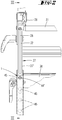
Figur 1 - Fig. 3
- den Schnitt gemäß der Linie III - III in
Figur 2 - Fig. 4
- das Detail IV - IV in
Figur 1 - Fig. 5
- eine Darstellung gemäß
Figur 4 jedoch mit teilweise weggebrochener Flanschplatte 11, - Fig. 6
- ein Detail in Blickrichtung VI in
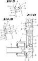
Figur 4 - Fig. 7
- den Schnitt gemäß der Linie VII - VII in
Figur 4darstellend das Klemmelement 6 in seiner an der Klemmflanke 7 anliegenden Klemmstellung und des inder Rastnische 5einliegenden Rastzapfens 4, - Fig. 8
- eine Darstellung gemäß
Figur 7 jedoch mit weggebrochener Klemmflanke 7 und Rastnische 5, - Fig. 9
- den Schnitt gemäß der Linie IX - IX in
Figur 6 - Fig. 10
- den Schnitt gemäß
Figur 9mit dem Klemmelement 6 in seiner Freigabestellung, - Fig. 11
- den Schnitt gemäß der Linie XI - XI in
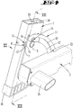
Figur 6 - Fig. 12
- das Detail XII - XII in
Figur 1 - Fig. 13
- den Schnitt gemäß der Linie XIII - XIII in
Figur 12 - Fig. 14
- eine teilweise aufgebrochene Detaildarstellung gemäß
Figur 12
- Fig. 1
- in a perspective view of the embodiment in the form of a clamping table,
- Fig. 2
- the detail in viewing direction II in
FIG. 1 . - Fig. 3
- the section according to the line III - III in
FIG. 2 . - Fig. 4
- the detail IV - IV in
FIG. 1 . - Fig. 5
- a representation according to
FIG. 4 but with partly brokenflange plate 11, - Fig. 6
- a detail in view VI in
FIG. 4 . - Fig. 7
- the section according to the line VII - VII in
FIG. 4 , showing theclamping element 6 in its clamping position abutting the clamping flank 7 and the latchingpin 4 lying in thelatching recess 5, - Fig. 8
- a representation according to
FIG. 7 but withbroken clamping edge 7 and 5 niche, - Fig. 9
- the section according to the line IX - IX in
FIG. 6 , with the clamping element in its clamping position, - Fig. 10
- the cut according to
FIG. 9 but with the clampingelement 6 in its release position, - Fig. 11
- the section according to the line XI - XI in
FIG. 6 . - Fig. 12
- the detail XII - XII in
FIG. 1 . - Fig. 13
- the section according to the line XIII - XIII in
FIG. 12 and - Fig. 14
- a partially broken detail according to
FIG. 12 ,
Die
Der Träger 28 ist ein Spannbackenträger, auf dessen nach oben weisender Seite zwei Spannbacken 29, 30 angeordnet sind, die mittels eines Spindeltriebs aufeinander zu verlagerbar sind. Die Oberseiten der Spannbacken 29, 30 bilden Werkflächen. In den Werkflächen befinden sich Längsschlitze 47, 48. Die Erstreckungsrichtung der Längsschlitze 47, 48 ist quer zu einer Verstellrichtung, in welcher Verstellrichtung die beiden Spannbacken 29, 30 mittels Kurbeln und einem Spindeltrieb aufeinander zu verlagert werden können. Die Spannbacke 29 ist sowohl in Vertikalrichtung, als auch in Horizontalrichtung fest mit dem Träger 28 verbunden. Die Spannbacke 30 ist in Horizontalrichtung fest mit dem Träger 28 verbunden, jedoch durch Betätigen des Spindeltriebes gegenüber der festen Spannbacke 29 verlagerbar. Als Folge dessen verlagert sich auch der Abstand der Längsschlitze 48 der Spannbacke 30 zu den Längsschlitzen 47 der Spannbacke 29.The
In den Spannbacken 29, 30 sind mehrere in einer Richtung quer zur Verstellrichtung nebeneinander liegende Längsschlitze 47, 48 und mehrere in Verstellrichtung nebeneinander liegende Längsschlitze 47, 48 vorgesehen. Die von Langlöchern gebildeten Längsschlitze erstrecken sich quer zur Verstellrichtung und dienen der Befestigung von Werkzeugaufnahmeplatten. Eine derartige Werkzeugaufnahmeplatte kann bspw. mit vier Schrauben an der Werkfläche befestigt werden, wobei jeweils zwei Schrauben in zwei Längsschlitze 47 der Spannbacke 29 und zwei weitere Schrauben in zwei Längsschlitze 48 der Spannbacke 30 eingreifen. Ein Elektromotor bzw. ein elektromotorisch angetriebenes Werkzeug, welches an der mit den Spannbacken verschraubten Befestigungsplatte befestigt ist, befindet sich dann zwischen den beiden Spannbacken 29, 30.In the clamping
In unmittelbarer Nachbarschaft zu den Füßen 36 ist an den ersten Tragelementen jeweils ein zweites Tragelement 2 schwenkbar angeordnet. Das freie Ende des zweiten Tragelementes 2 trägt ebenfalls einen Fuß 37. Die beiden zweiten Tragelemente 2 sind mittels der Verbindungselemente 35 starr miteinander verbunden.In the immediate vicinity of the
Die Schwenkachse 3, um die das zweite Tragelement 2 von der in der
Am zweiten Tragelement 2 ist eine Flanschplatte 11 befestigt. Die Flanschplatte 11 besitzt eine Breitseitenfläche, die an einer Breitseitenfläche des Vierkantrohres 1 anliegt. Die Breitseitenfläche des Vierkantrohres 1 besitzt ein erstes schlitzförmiges Fenster 13 und ein zweites schlitzförmiges Fenster 14. Durch das erste schlitzförmige Fenster 13 ragt der Kopf eines Klemmelementes 6 heraus. Bei dem Klemmelement 6 handelt es sich um einen Klemmhebel, der um eine Schwenkachse 16 schwenkbar am ersten Tragelement 1 gelagert ist. Der Klemmhebel 6 lässt sich von einer Verriegelungsstellung, die in der
Ein kurzes Ende 17 des Klemmhebels 6 ragt aus dem dem ersten Fenster 13 gegenüberliegenden zweiten Fenster 14.On the
A
Das erste Tragelement 1 bildet ein Vierkantrohr aus, mit zwei ersten parallel zueinander verlaufenden Seitenwänden, zu denen die Schwenkachse 3 in Querrichtung verläuft. Zwei zweite Breitseitenflächen des ersten Tragelementes erstrecken sich quer zu den ersten Breitseitenflächen. Quer zu den zweiten Breitseitenflächen erstreckt sich die Schwenkachse 16, um die das Klemmelement schwenkbar ist. Die beiden Schwenkachsen 3, 16 sind in Erstreckungsrichtung des ersten Tragelementes voneinander beabstandet.The
Innerhalb der Höhlung des ersten Tragelementes 1 befindet sich ein Betätigungsglied 18. Das Betätigungsglied 18 besitzt zwei seitlich abragende Flügel 23, 23', die mit Bewegungsspiel an den Innenflächen der beiden kürzeren Seitenflächen des Tragelementes 1 anliegen können. Eine dieser kürzeren Seitenwände ist Trägerin der Schwenkachse 16 des Klemmelementes 6.Within the cavity of the
Das Betätigungsglied 18 trägt einen Rastzapfen 4, der aus dem Fenster 14 aus der Höhlung des ersten Tragelementes herausragt. In der in den Zeichnungen dargestellten Gebrauchsstellung des Tragegestells liegt der Rastzapfen 4 in einer Rastnische 5 der Flanschplatte 11. An die Rastnische 5 schließt sich eine auf einer Kreisbogenlinie um die Schwenkachse 3 verlaufende Führungsflanke 12' an, die von der Randkante eines bogenförmigen Führungsschlitzes 12 gebildet ist.The actuator 18 carries a
Die Schwenkachse 3 durchgreift ein Widerlager 39, welches sich innerhalb des ersten Tragelementes 1 befindet. Sie fesselt das Widerlager 39 an das erste Tragelement. Am Widerlager 39 ist ein Ende einer Zugfeder 25 befestigt. Das andere Ende der Zugfeder 25 ist am Betätigungsglied 18 befestigt. Die Zugfeder 25 beaufschlagt das Betätigungsglied 18 derart, dass der Rastzapfen 4 in der Rastnische 5 gehalten ist. Am Betätigungsglied 18 greift eine Zugstange 26 an, die sich durch die Rohrhöhlung des ersten Tragelementes 1 hindurch bis in die Rohrhöhlung des Stützelementes 27 erstreckt, wo ein Betätigungsende der Zugstange 26 durch einen Schlitz 32, der sich in Erstreckungsrichtung des Stützelementes 27 erstreckt, aus der Höhlung des Stützelementes 27 herausragt. Daran ist eine Handhabe 31 befestigt, die sich parallel zu dem Verbindungselement 38 erstreckt. Wird die Handhabe 31 nach oben gezogen, so verlagert sich das Betätigungsglied 18 ebenfalls nach oben, so dass der Rastzapfen 4 aus der Rastnische 5 heraustritt. Dies erfolgt gegen die Rückstellkraft der Feder 25. Das Widerlager 39 besitzt eine seitliche Ausnehmung, in der eine Buchse 41 eingreift. Die Buchse 41 durchgreift eine Öffnung der Wandung des Tragelementes 1 und eine Öffnung der Flanschplatte 11. Ein Stirnrand der Buchse 41 stützt sich an der Außenseite des zweiten Tragelementes 2 ab. Die Öffnung 42 der Wandung des ersten Tragelementes 1 umgibt im Wesentlichen passgenau die Außenwandung der Buchse 41, durch die die Schwenkachse 3 verläuft.The
Zwischen der Außenwandung des Tragelementes 1 und der Flanschplatte 11 befindet sich eine Passscheibe 43, die die Flanschplatte 11 geringfügig von der Außenwandung des Tragelementes 1 beabstandet hält.Between the outer wall of the
Der Flügel 23 des Betätigungsgliedes 18 besitzt ein Fenster 21, welches mit Bewegungsspiel nach oben und unten vom Klemmelement 6 durchgriffen ist. Nimmt das Betätigungsglied 18 seine in den Zeichnungen dargestellte Verriegelungsstellung ein, in der der Rastzapfen 4 in der Rastnische 5 liegt, so wird der lange Hebelarm des Klemmelementes 6 in unmittelbarer Nachbarschaft des Schlitzes 13 innenseitig des Tragelementes 1 von einer Druckflanke 19 des Fensters 21 nach unten durch die Zugkraft der Zugfeder 25 beaufschlagt. Wird das Betätigungsglied 18 nach oben verlagert, so findet zunächst ein Freigang statt, bis die Hubflanke 20 am Klemmelement 6 anschlägt. Bei einer weiteren Aufwärtsverlagerung des Betätigungsgliedes 18 wird das Klemmelement 6 um die Schwenkachse 16 von der in
Die
Der Gegenanschlag 10 liegt in berührender Anlage am Anschlag 9.The counter-stop 10 is in touching contact with the
Die Bewegungsebene B innerhalb der sich das Klemmelement 6 schwenkverlagern kann, bildet einen unterhalb der Selbsthemmung liegenden flachen Winkel zur Klemmflanke 7, die von einer im Wesentlichen geradlinig verlaufenden Randkante der Flanschplatte 11 ausgebildet ist. Zufolge der Belastung des Klemmelementes 6 durch die Zugfeder 25 übt der aus dem Fenster 13 herausragende Kopf des Klemmelementes 6 eine Spannkraft bzw. eine Klemmkraft auf die Klemmflanke 7 aus. Das dadurch in die Flanschplatte 11 eingebrachte Drehmoment wird auf den Anschlag 9 übertragen. Der Kopf des Klemmelementes 6 stützt sich dabei mit einem ersten Abschnitt an der Klemmflanke 7 ab. Ein diesem Abschnitt gegenüberliegender Abschnitt des Klemmelementes 6 stützt sich an einer Randkante 13' des Schlitzes 13 ab.The plane of movement B within which the
Alternativ dazu oder in Kombination kann der Anschlag 9 vom Gegenanschlag 10 aber auch toleranzbedingt beabstandet sein, so dass sich in der Verriegelungsstellung ein Randabschnitt des Rastzapfens 4 an einer Randkante 14' des Schlitzes 14 abstützt und ein diesem Abschnitt des Rastzapfens 4 gegenüberliegender Abschnitt von einem Wandungsabschnitt 18 der Rastnische 5 beaufschlagt wird.Alternatively, or in combination, the
Aus der
Um das zweite Tragelement 2 von der Gebrauchsstellung in die NichtGebrauchsstellung zu verschwenken wird das Betätigungsglied 18 durch Zug an der Handhabe 31 in eine aufwärts verlagerte Stellung gebracht. Einhergehend damit wird der Rastzapfen 4 aus der Rastnische 5 in eine Freigabestellung gehoben. Durch Angriff der Hubflanke 20 an dem langen Ende des insbesondere Bewegungsspiel das Fenster 21 durchgreifenden Klemmhebels 6 wird der Klemmhebel 6 ebenfalls in die in
An dem der Rastnische 5 gegenüberliegenden Ende des Führungsschlitzes 12 befindet sich eine Nische 40 in die der Rastzapfen 5 in einer Verwahrstellung des zweiten Tragelementes 2 eintreten kann.At the opposite end of the latching
Um das zweite Tragelement 2 zurück in die Gebrauchsstellung zu verschwenken, muss ein geringfügiges Drehmoment auf das zweite Tragelement 2 aufgebracht werden, welches ausreicht, den Rastzapfen 4 aus der Nische 40 zu verlagern. Nach Erreichen der Schwenkendstellung fällt der Rastzapfen 4 von der Kraft der vorgespannten Zugfeder 25 beaufschlagt in die Rastnische 5. Die Druckflanke 19 beaufschlagt den Klemmhebel 6 in die in der
Einen weiteren Aspekt der Erfindung betrifft die Höhenverstellbarkeit des Stützelementes 27, das teleskopierbar im ersten Tragelement 1 steckt. Die diesbezüglichen Mittel werden in den
Die lichte Öffnung zwischen den beiden Schmalseitenwänden des ersten Tragelementes ist ausreichend größer als der Abstand der Außenseiten der voneinander wegweisenden Schmalseiten 27', 27" des Stützelementes 27, damit das Stützelement 27 durch eine Schwenkbewegung in und außer Eingriff einer Formschlussrast mit dem Formschlusshaltemittel 44 bringbar ist. In der Eingriffs stellung greift der Senkkopf 44 in eine von mehreren Öffnungen 45 der Schmalseitenwand 27' ein. Ein Rand der Öffnung 45 liegt dabei auf einem nach oben weisenden Abschnitt des konusförmigen Mantelwandabschnitts des Senkkopfes 44. Durch eine geringfügige Hubbewegung kann der Hakeneingriff aufgehoben werden. Durch die Schwenkbewegung tritt der Schraubenkopf 44 aus der Öffnung 45 heraus, so dass das Stützelement 27 in seiner Erstreckungsrichtung verschoben werden kann. Einhergehend damit ändert sich die Höhenlage des Trägers 28. Durch eine erneute Schwenkbewegung kann der Schraubenkopf 44 in eine andere Öffnung 45 eingehakt werden. Das Schwenkbewegungsspiel ist größer als das Maß des Überstandes des Formschlusshalteelementes 44 über die Innenseite der Seitenwandung des Tragelementes 1. Die
Zur Aufhebung der Rast muss ausgehend von der in
Die einen rechteckigen Querschnitt aufweisende Feder 34 nimmt dabei einen Teil des Gewichtes des Trägers 28 und der Spannbacken auf. Das obere Ende der Wendelgangfeder 34 besitzt einen geringeren Querschnitt, als der untere Abschnitt des Federelementes und steckt auf einem rechteckigen Fortsatz an der Unterseite des Stützelementes 27.The
Die vorstehenden Ausführungen dienen der Erläuterung der von der Anmeldung insgesamt erfassten Erfindungen, die den Stand der Technik zumindest durch die folgenden Merkmalskombinationen jeweils eigenständig weiterbilden, nämlich:
Ein Tragegestell, das dadurch gekennzeichnet ist, dass die Halteelemente 6, 7; 4, 5; 9, 10 ein einem der beiden Tragelemente 1 zugeordnetes Klemmelement 6 aufweisen, das in der Verriegelungsstellung an einer dem anderen Tragelement 2 zugeordneten Klemmflanke 7 klemmend anliegt.The above explanations serve to explain the inventions as a whole covered by the application, which independently further develop the state of the art, at least by the following combinations of features, namely:
A support frame, which is characterized in that the holding
Ein Tragegestell, das dadurch gekennzeichnet ist, dass das Klemmelement 6 ein um eine Schwenkachse 16 verschwenkbarer Hebel ist, der insbesondere im Inneren eines vom ersten Tragelement 1 ausgebildeten Hohlkörpers angeordnet ist und einen durch ein Fenster 13 aus dem Hohlraum herausragenden Kopf aufweist, der in einer Schwenkebene B verlagerbar ist, die spitzwinklig zur Klemmflanke 7 verläuft, die insbesondere von einer fest mit dem zweiten Tragelement 2 verbundenen Flanschplatte 11 ausgebildet ist.A support frame, which is characterized in that the clamping
Ein Tragegestell, das dadurch gekennzeichnet ist, dass die Haltemittel 6,7; 4, 5; 9, 10 in der ersten Schwenkstellung berührend aneinander liegende Festanschläge 9, 10 ausbilden, wobei insbesondere dem ersten Tragelement 1 ein Anschlag 9 und dem zweiten Tragelement 2 ein Gegenanschlag 10 zugeordnet ist.A support frame, which is characterized in that the holding means 6,7; 4, 5; 9, 10 in the first pivot position contacting contiguous
Ein Tragegestell, das dadurch gekennzeichnet ist, dass die Halteelemente 6, 7; 4, 5; 9, 10 einen Rastzapfen 4 aufweisen, der in der Verriegelungsstellung in einer Rastnische 5 einliegt und der insbesondere zusammen mit dem Klemmelement 6 von der Verriegelungsstellung in die Freigabestellung verlagerbar ist.A support frame, which is characterized in that the holding
Ein Tragegestell, das dadurch gekennzeichnet ist, dass das erste Tragelement 1 ein rohrförmiger Körper ist, mit einem innerhalb des Rohres angeordneten Betätigungsglied 18, das insbesondere gegen die Kraft einer Feder 25 in Erstreckungsrichtung des ersten Tragelementes 1 verlagerbar ist und Träger des Rastzapfens 4 ist und bei seiner Verlagerung von der Verriegelungsstellung in die Freigabestellung das Klemmelement 6 mit in die Freigabestellung verlagert, wobei insbesondere vorgesehen ist, dass ein Arm des Klemmelementes 6 ein Fenster 21 des Betätigungsgliedes 18 durchragt, welches Fenster 21 eine Hubflanke 20 und eine Druckflanke 19 ausbildet.A support frame, which is characterized in that the
Ein Tragegestell, das dadurch gekennzeichnet ist, dass das Klemmelement 6 eine Stirnfläche 15 aufweist, die sich beim Verschwenken von der ersten Schwenkstellung in die zweite Schwenkstellung an einer Breitseitenfläche der Flanschplatte 11 abstützt, die beim Verschwenken der beiden Tragelemente 1, 2 an dem Fenster 13 des Tragelementes 1 vorbei schwenkt.A support frame, which is characterized in that the clamping
Ein Tragegestell, das dadurch gekennzeichnet ist, dass das Fenster 13 ein Schlitz mit einer Randkante 13' ist an welcher Randkante 13' sich das Klemmelement 6 mit einem ersten Abschnitt abstützt, wobei sich ein vom ersten Abschnitt wegweisender zweiter Abschnitt an der Klemmflanke 7 abstützt.A support frame, which is characterized in that the
Ein Tragegestell, das dadurch gekennzeichnet ist, dass der Rastzapfen 4 mit toleranzbedingtem Bewegungsspiel in der Rastnische 5 einliegt, an die sich eine Führungsflanke 12' anschließt, an der der in eine Freigabestellung gebrachte Rastzapfen 4 beim Verschwenken der Tragelemente 1, 2 entlang gleitet.A support frame, which is characterized in that the
Ein Tragegestell, das dadurch gekennzeichnet ist, dass das erste Tragelement 1 an seinem in einer der ersten Schwenkstellung entsprechenden Gebrauchsstellung des Tragegestells nach unten weisenden Ende einen ersten Fuß 36 ausbildet, dass das zweite Tragelement 2 in unmittelbarer Nachbarschaft des ersten Fußes 36 am ersten Tragelement 1 angelenkt ist und mit seinem freien Ende einen zweiten Fuß 37 ausbildet.A support frame, which is characterized in that the
Ein Tragegestell, das dadurch gekennzeichnet ist, dass ein Tragelementepaar 1, 2 vier Füße 36, 37 ausbildend mit Verbindungselementen 35, 38 miteinander verbunden ist und das erste Tragelement 1 mit seinem in der Gebrauchsstellung nach oben weisenden Ende einen Träger 28, insbesondere einen Spannbacken 29, 30 tragenden Träger 28 trägt, und/ oder, dass in den Spannbacken 29, 30 quer zu einer Verstellrichtung der beiden Spannbacken 29, 30 sich erstreckende Längsschlitze 47, 48 vorgesehen sind.A support frame, which is characterized in that a
Ein Tragegestell, das dadurch gekennzeichnet ist, dass in der Höhlung des ersten Tragelementes 1 ein Stützelement 27 teleskopierbar angeordnet ist, in welchem ein Betätigungsende eines am Betätigungsglied 18 angreifenden Zugelementes 26 angeordnet ist, wobei insbesondere vorgesehen ist, dass das Tragelement 27 einen Schlitz 32 aufweist, durch den ein mit einer Handhabe 31 verbundenes Betätigungsende des Zugelementes 26 herausragt.A support frame, which is characterized in that in the cavity of the
Ein Tragegestell, das dadurch gekennzeichnet ist, dass das Formschlusshalteelement durch eine Schwenkbewegung des Stützelementes 27 gegenüber dem Tragelement 1 in und außer Eingriff in eine Rastöffnung 45 bringbar ist.A support frame, which is characterized in that the positive
Ein Tragegestell, das dadurch gekennzeichnet ist, dass das Formschlusshalteelement 44 vom Kopf einer Senkkopfschraube ausgebildet ist, welcher Kopf 44 mit seinem Konusabschnitt einen Haken ausbildet, so dass das Formschlusshalteelement durch eine Hub-/Schwenk-Bewegung des Stützelementes in und außer Eingriff in eine Rastöffnung 45 bringbar ist.A support frame, which is characterized in that the form-fitting
Ein Tragegestell, das dadurch gekennzeichnet ist, dass das Formschlusseingriffselement 44 unmittelbar benachbart dem Rand einer Öffnung eines das Tragelement 1 ausbildenden Rohres angeordnet ist und an der Innenwand des Rohres befestigt ist.A support frame, characterized in that the form-fitting
Ein Tragegestell, das dadurch gekennzeichnet ist, dass an dem im Tragelement 1 steckenden Ende des Stützelementes ein Stütznocken 46 angeordnet ist, der von der Wandung des Stützelementes 27 abragt und sich an der Innenseite der schräg nach oben weisenden Wandung des Tragelementes (1) abstützt.A support frame, which is characterized in that on the plug-in
Die Unteransprüche charakterisieren mit ihren Merkmalen eigenständige erfinderische Weiterbildungen des Standes der Technik, insbesondere um auf Basis dieser Ansprüche Teilanmeldungen vorzunehmen.
Claims (13)
- Support frame, in particular workbench or workpiece support comprising a first support element (1), a second support element (2) pivotally hinged thereto and retaining elements (6, 7; 4, 5; 9, 10) which are associated with the two support elements (1, 2) and which fix the two support elements (1, 2) in a first pivot position when in a locking position and allow pivoting of the support elements (1, 2) into a second pivot position when in a release position, the retaining elements (6, 7; 4, 5; 9, 10) having a clamping element (6) and a fixed stop (9) which are associated with the first support element (1), the clamping element (6) being in clamping contact with a clamping flank (7) of the second support element (2) when in the locking position, characterised in that the clamping flank (7) is a peripheral edge of a flange plate (11) associated with the second support element (2), which plate forms a counter stop (10) for the fixed stop (9).
- Support frame according to claim 1, characterised in that the clamping element (6) is a lever which can be pivoted about a pivot axis (16) and is arranged in particular in the interior of a hollow body formed by the first support element (1) and comprises a head which projects from the hollow space through an aperture (13) and can be displaced in a pivot plane (B) which extends at an acute angle to the clamping flank (7).
- Support frame according to any of the preceding claims, characterised in that the retaining elements (6, 7; 4, 5; 9, 10) have a locking pin (4) which engages in a locking recess (5) when in the locking position and which, in particular together with the clamping element (6), can be displaced from the locking position into the release position.
- Support frame according to claim 3, characterised in that the first support element (1) is a tubular body comprising an actuating member (18) which is arranged inside the tube and can be displaced in the extension direction of the first support element (1), in particular against the force of a spring (25), is a support for the locking pin (4), and, when displaced from the locking position into the release position, displaces the clamping element (6) into the release position therewith, it being provided in particular that one arm of the clamping element (6) projects through an aperture (21) in the actuating member (18), which aperture (21) forms a lifting flank (20) and a pressure flank (19).
- Support frame according to any of claims 2 to 4, characterised in that the clamping element (6) has an end face (15) which is supported on a broad-side face of the flange plate (11) when it pivots from the first pivot position into the second pivot position, which plate pivots past the aperture (13) in the support element (1) when the two support elements (1, 2) pivot.
- Support frame according to any of claims 2 to 5, characterised in that the aperture (13) is a slot having a peripheral edge (13') on which peripheral edge (13') a first portion of the clamping element (6) is supported, a second portion that points away from the first portion being supported on the clamping flank (7).
- Support frame according to any of claims 3 to 6, characterised in that the locking pin (4) engages in the locking recess (5) with tolerance-related movement play, a guide flank (12') being adjacent to said recess, along which flank the locking pin (4) that has been brought into a release position slides when the support elements (1, 2) pivot.
- Support frame according to any of the preceding claims, characterised in that the first support element (1) forms a first foot (36) at its end that points downwards in a use position of the support frame that corresponds to the first pivot position, in that the second support element (2) is articulated on the first support element (1) in the immediate vicinity of the first foot (36) and the free end of said support element forms a second foot (37).
- Support frame according to any of the preceding claims, characterised in that a support element pair (1, 2) forming four feet (36, 37) is interconnected with connecting elements (35, 38) and the end of the first support element (1) that points upwards in the use position supports a support (28), in particular a support (28) supporting clamping jaws (29, 30), and/or in that extending longitudinal slots (47, 48) are provided in the clamping jaws (29, 30) transversely to an adjustment direction of the two clamping jaws (29, 30).
- Support frame according to any of the preceding claims, characterised in that a supporting element (27) is arranged telescopically in the cavity of the first support element (1), in which supporting element an actuating end of a tension element (26) acting on the actuating member (18) is arranged, it being provided in particular that the support element (27) has a slot (32) through which an actuating end of the tension element (26) connected to a handle (31) projects.
- Support frame according to any of the preceding claims, characterised by a base frame which can be placed on a base and which has at least one elongate support element (1) which projects obliquely upwards in a vertical plane, in which support element an elongate supporting element (27) is telescopically inserted, at the upper end of which a support (28) is fastened, it being possible for the supporting element (27) to be fixed to the support element (1) by means of a form-fitting retaining element (44) engaging in a locking opening (45) at different height positions of the support (28), it being possible for the form-fitting retaining element to be brought into and out of engagement in a locking opening (45) by a pivoting movement of the supporting element (27) relative to the support element (1).
- Support frame according to claim 12, characterised in that the form-fitting retaining element (44) is formed by the head of a countersunk screw, the bevel portion of which head (44) forms a hook such that the form-fitting retaining element can be brought in and out of engagement in a locking opening (45) by a lifting/pivoting movement of the supporting element.
- Support frame according to either claim 12 or claim 13, characterised in that the form-fitting retaining element (44) is arranged immediately adjacently to the periphery of an opening in a tube forming the support element (1) and is fastened to the inner wall of the tube and/or in that a supporting protrusion (46) is arranged on the end of the supporting element inserted in the support element (1), which protrusion projects from the wall of the supporting element (27) and is supported on the inside of the obliquely upwardly facing wall of the support element (1).
Priority Applications (1)
| Application Number | Priority Date | Filing Date | Title |
|---|---|---|---|
| EP19187378.5A EP3593953B1 (en) | 2014-05-16 | 2015-05-07 | Support frame with lockable rattle-free support elements |
Applications Claiming Priority (1)
| Application Number | Priority Date | Filing Date | Title |
|---|---|---|---|
| DE102014106961.7A DE102014106961A1 (en) | 2014-05-16 | 2014-05-16 | Carrying rack with rattle-free lockable support elements |
Related Child Applications (2)
| Application Number | Title | Priority Date | Filing Date |
|---|---|---|---|
| EP19187378.5A Division EP3593953B1 (en) | 2014-05-16 | 2015-05-07 | Support frame with lockable rattle-free support elements |
| EP19187378.5A Division-Into EP3593953B1 (en) | 2014-05-16 | 2015-05-07 | Support frame with lockable rattle-free support elements |
Publications (3)
| Publication Number | Publication Date |
|---|---|
| EP2944436A2 EP2944436A2 (en) | 2015-11-18 |
| EP2944436A3 EP2944436A3 (en) | 2016-12-14 |
| EP2944436B1 true EP2944436B1 (en) | 2019-11-13 |
Family
ID=53268623
Family Applications (2)
| Application Number | Title | Priority Date | Filing Date |
|---|---|---|---|
| EP15166717.7A Active EP2944436B1 (en) | 2014-05-16 | 2015-05-07 | Support frame with lockable rattle-free support elements |
| EP19187378.5A Active EP3593953B1 (en) | 2014-05-16 | 2015-05-07 | Support frame with lockable rattle-free support elements |
Family Applications After (1)
| Application Number | Title | Priority Date | Filing Date |
|---|---|---|---|
| EP19187378.5A Active EP3593953B1 (en) | 2014-05-16 | 2015-05-07 | Support frame with lockable rattle-free support elements |
Country Status (3)
| Country | Link |
|---|---|
| EP (2) | EP2944436B1 (en) |
| DE (1) | DE102014106961A1 (en) |
| ES (1) | ES2872174T3 (en) |
Families Citing this family (9)
| Publication number | Priority date | Publication date | Assignee | Title |
|---|---|---|---|---|
| CN105598710A (en) * | 2016-02-25 | 2016-05-25 | 莫焕东 | Angle-adjustable working platform convenient to operate |
| CN105598928A (en) * | 2016-02-25 | 2016-05-25 | 莫焕东 | Novel angle-adjustable intelligent working platform device |
| CN105598930A (en) * | 2016-02-25 | 2016-05-25 | 任泽威 | Angle-adjustable working table mechanism controlled by threaded rods |
| CN108656570B (en) * | 2018-04-18 | 2024-03-08 | 中储粮成都储藏研究院有限公司 | Grain membrane sealing groove pressing pipe device |
| CN108908227A (en) * | 2018-05-31 | 2018-11-30 | 河南欧文包装制品有限公司 | A kind of disposable lunch-box production and processing workbench |
| CN110762363A (en) * | 2019-10-22 | 2020-02-07 | 浙江华丰电动工具有限公司 | Integrated folding foot stool |
| CN111645042B (en) * | 2020-05-09 | 2021-11-30 | 泰州市光明电子材料有限公司 | Angle-adjusting workbench for automobile electronic product production |
| CN112518687B (en) * | 2020-12-08 | 2022-08-09 | 深圳市韩安特科技有限公司 | Display screen bearing device |
| CN215920370U (en) * | 2021-04-21 | 2022-03-01 | 杭州巨星科技股份有限公司 | Saw frame |
Family Cites Families (11)
| Publication number | Priority date | Publication date | Assignee | Title |
|---|---|---|---|---|
| CH347966A (en) | 1957-03-02 | 1960-07-31 | Egger Fritz | Collapsible jack |
| GB1267033A (en) | 1968-03-04 | 1972-03-15 | ||
| US4144822A (en) | 1977-01-24 | 1979-03-20 | Roberts Mfg., Inc. | Folding leg mechanism |
| DE19735336A1 (en) | 1997-08-14 | 1999-02-18 | Wolfcraft Gmbh | Work table |
| IL125793A (en) * | 1998-08-14 | 2003-05-29 | Z A G Ind Ltd | Height and working width adjustable sawhorse |
| DE19909830A1 (en) | 1999-03-05 | 2000-09-07 | Wolfcraft Gmbh | Workbench |
| US6712180B2 (en) * | 2002-03-01 | 2004-03-30 | Zag Industries Ltd. | Height adjustable sawhorse |
| US6883793B2 (en) | 2002-09-17 | 2005-04-26 | Black & Decker Inc. | Portable workbench having collapsible support structure |
| CN2649283Y (en) | 2003-07-17 | 2004-10-20 | 南京泉峰国际贸易有限公司 | Foldable support for cutting machine |
| US20050051940A1 (en) * | 2003-09-05 | 2005-03-10 | Zag Industries, Ltd. | Work stand |
| EP2599595B1 (en) * | 2011-12-01 | 2017-10-11 | The Stanley Works Israel Ltd. | Adjustable sawhorse |
-
2014
- 2014-05-16 DE DE102014106961.7A patent/DE102014106961A1/en active Pending
-
2015
- 2015-05-07 ES ES19187378T patent/ES2872174T3/en active Active
- 2015-05-07 EP EP15166717.7A patent/EP2944436B1/en active Active
- 2015-05-07 EP EP19187378.5A patent/EP3593953B1/en active Active
Non-Patent Citations (1)
| Title |
|---|
| None * |
Also Published As
| Publication number | Publication date |
|---|---|
| EP3593953A1 (en) | 2020-01-15 |
| ES2872174T3 (en) | 2021-11-02 |
| EP2944436A3 (en) | 2016-12-14 |
| EP2944436A2 (en) | 2015-11-18 |
| DE102014106961A1 (en) | 2015-11-19 |
| EP3593953B1 (en) | 2021-04-14 |
Similar Documents
| Publication | Publication Date | Title |
|---|---|---|
| EP2944436B1 (en) | Support frame with lockable rattle-free support elements | |
| EP2222202B1 (en) | Drawer with front-adjustment | |
| EP2851497B1 (en) | Adjustable mounting device for a sliding element and sliding device | |
| EP3215099B1 (en) | Gripping claw for mounting on a slide rail of an operating table | |
| DE102010060722B4 (en) | Connecting fitting | |
| EP3138674B1 (en) | Device for carrying out mitre cuts | |
| WO2010136228A1 (en) | Device for fastening a front panel to a side section of a movable furniture part, drawer and item of furniture | |
| EP3556978A1 (en) | Device for moving a piece of furniture on a body of a piece of furniture | |
| DE202009014811U1 (en) | Furniture fitting for releasably connecting two furniture parts | |
| EP1877713B1 (en) | Refrigerating and/or freezing apparatus | |
| DE102008060126A1 (en) | clamping system | |
| AT505970A1 (en) | WEARING CONSTRUCTION FOR AT LEAST ONE FURNITURE DRIVE | |
| WO2012156340A1 (en) | Fitting for a sliding door | |
| EP1888280B1 (en) | Connection between two tool parts | |
| DE112013007025B4 (en) | Locking device for telescopic furniture column, furniture and processes | |
| CH716837A1 (en) | Wind bandage and furniture kit. | |
| AT507690B1 (en) | FURNITURE FITTING FOR SOLDER CONNECTING TWO FURNITURE PARTS | |
| EP1794053B1 (en) | Device for fixing an object to a rail | |
| DE102013218868A1 (en) | Actuator assembly and release lever for this | |
| EP2233039B1 (en) | Drawer guide | |
| AT519906A1 (en) | hinge | |
| DE102014210314A1 (en) | Fastening device for fastening an object to a wall and fastening system | |
| AT525757B1 (en) | Locking device for a movable bunker wall | |
| AT411131B (en) | EXTENDING FRAME FOR CUPBOARD UNITS WITH VERTICAL AND HORIZONTAL FRAME LEGS FROM PROFILE RAILS | |
| AT522096B1 (en) | Arrangement with at least one drawer pull-out guide and with at least one locking device for releasably locking a pull-out furniture part |
Legal Events
| Date | Code | Title | Description |
|---|---|---|---|
| PUAI | Public reference made under article 153(3) epc to a published international application that has entered the european phase |
Free format text: ORIGINAL CODE: 0009012 |
|
| AK | Designated contracting states |
Kind code of ref document: A2 Designated state(s): AL AT BE BG CH CY CZ DE DK EE ES FI FR GB GR HR HU IE IS IT LI LT LU LV MC MK MT NL NO PL PT RO RS SE SI SK SM TR |
|
| AX | Request for extension of the european patent |
Extension state: BA ME |
|
| PUAL | Search report despatched |
Free format text: ORIGINAL CODE: 0009013 |
|
| AK | Designated contracting states |
Kind code of ref document: A3 Designated state(s): AL AT BE BG CH CY CZ DE DK EE ES FI FR GB GR HR HU IE IS IT LI LT LU LV MC MK MT NL NO PL PT RO RS SE SI SK SM TR |
|
| AX | Request for extension of the european patent |
Extension state: BA ME |
|
| RIC1 | Information provided on ipc code assigned before grant |
Ipc: B25H 1/04 20060101AFI20161107BHEP Ipc: B25H 1/16 20060101ALI20161107BHEP |
|
| STAA | Information on the status of an ep patent application or granted ep patent |
Free format text: STATUS: REQUEST FOR EXAMINATION WAS MADE |
|
| 17P | Request for examination filed |
Effective date: 20170327 |
|
| RBV | Designated contracting states (corrected) |
Designated state(s): AL AT BE BG CH CY CZ DE DK EE ES FI FR GB GR HR HU IE IS IT LI LT LU LV MC MK MT NL NO PL PT RO RS SE SI SK SM TR |
|
| GRAP | Despatch of communication of intention to grant a patent |
Free format text: ORIGINAL CODE: EPIDOSNIGR1 |
|
| STAA | Information on the status of an ep patent application or granted ep patent |
Free format text: STATUS: GRANT OF PATENT IS INTENDED |
|
| INTG | Intention to grant announced |
Effective date: 20190424 |
|
| GRAS | Grant fee paid |
Free format text: ORIGINAL CODE: EPIDOSNIGR3 |
|
| GRAJ | Information related to disapproval of communication of intention to grant by the applicant or resumption of examination proceedings by the epo deleted |
Free format text: ORIGINAL CODE: EPIDOSDIGR1 |
|
| GRAL | Information related to payment of fee for publishing/printing deleted |
Free format text: ORIGINAL CODE: EPIDOSDIGR3 |
|
| STAA | Information on the status of an ep patent application or granted ep patent |
Free format text: STATUS: REQUEST FOR EXAMINATION WAS MADE |
|
| INTC | Intention to grant announced (deleted) | ||
| GRAR | Information related to intention to grant a patent recorded |
Free format text: ORIGINAL CODE: EPIDOSNIGR71 |
|
| STAA | Information on the status of an ep patent application or granted ep patent |
Free format text: STATUS: GRANT OF PATENT IS INTENDED |
|
| GRAA | (expected) grant |
Free format text: ORIGINAL CODE: 0009210 |
|
| STAA | Information on the status of an ep patent application or granted ep patent |
Free format text: STATUS: THE PATENT HAS BEEN GRANTED |
|
| INTG | Intention to grant announced |
Effective date: 20191002 |
|
| AK | Designated contracting states |
Kind code of ref document: B1 Designated state(s): AL AT BE BG CH CY CZ DE DK EE ES FI FR GB GR HR HU IE IS IT LI LT LU LV MC MK MT NL NO PL PT RO RS SE SI SK SM TR |
|
| REG | Reference to a national code |
Ref country code: CH Ref legal event code: EP Ref country code: AT Ref legal event code: REF Ref document number: 1201177 Country of ref document: AT Kind code of ref document: T Effective date: 20191115 |
|
| REG | Reference to a national code |
Ref country code: DE Ref legal event code: R096 Ref document number: 502015010901 Country of ref document: DE |
|
| REG | Reference to a national code |
Ref country code: IE Ref legal event code: FG4D Free format text: LANGUAGE OF EP DOCUMENT: GERMAN |
|
| REG | Reference to a national code |
Ref country code: NL Ref legal event code: MP Effective date: 20191113 |
|
| REG | Reference to a national code |
Ref country code: LT Ref legal event code: MG4D |
|
| PG25 | Lapsed in a contracting state [announced via postgrant information from national office to epo] |
Ref country code: NL Free format text: LAPSE BECAUSE OF FAILURE TO SUBMIT A TRANSLATION OF THE DESCRIPTION OR TO PAY THE FEE WITHIN THE PRESCRIBED TIME-LIMIT Effective date: 20191113 Ref country code: BG Free format text: LAPSE BECAUSE OF FAILURE TO SUBMIT A TRANSLATION OF THE DESCRIPTION OR TO PAY THE FEE WITHIN THE PRESCRIBED TIME-LIMIT Effective date: 20200213 Ref country code: GR Free format text: LAPSE BECAUSE OF FAILURE TO SUBMIT A TRANSLATION OF THE DESCRIPTION OR TO PAY THE FEE WITHIN THE PRESCRIBED TIME-LIMIT Effective date: 20200214 Ref country code: FI Free format text: LAPSE BECAUSE OF FAILURE TO SUBMIT A TRANSLATION OF THE DESCRIPTION OR TO PAY THE FEE WITHIN THE PRESCRIBED TIME-LIMIT Effective date: 20191113 Ref country code: LT Free format text: LAPSE BECAUSE OF FAILURE TO SUBMIT A TRANSLATION OF THE DESCRIPTION OR TO PAY THE FEE WITHIN THE PRESCRIBED TIME-LIMIT Effective date: 20191113 Ref country code: LV Free format text: LAPSE BECAUSE OF FAILURE TO SUBMIT A TRANSLATION OF THE DESCRIPTION OR TO PAY THE FEE WITHIN THE PRESCRIBED TIME-LIMIT Effective date: 20191113 Ref country code: SE Free format text: LAPSE BECAUSE OF FAILURE TO SUBMIT A TRANSLATION OF THE DESCRIPTION OR TO PAY THE FEE WITHIN THE PRESCRIBED TIME-LIMIT Effective date: 20191113 Ref country code: PL Free format text: LAPSE BECAUSE OF FAILURE TO SUBMIT A TRANSLATION OF THE DESCRIPTION OR TO PAY THE FEE WITHIN THE PRESCRIBED TIME-LIMIT Effective date: 20191113 Ref country code: NO Free format text: LAPSE BECAUSE OF FAILURE TO SUBMIT A TRANSLATION OF THE DESCRIPTION OR TO PAY THE FEE WITHIN THE PRESCRIBED TIME-LIMIT Effective date: 20200213 Ref country code: PT Free format text: LAPSE BECAUSE OF FAILURE TO SUBMIT A TRANSLATION OF THE DESCRIPTION OR TO PAY THE FEE WITHIN THE PRESCRIBED TIME-LIMIT Effective date: 20200313 |
|
| PG25 | Lapsed in a contracting state [announced via postgrant information from national office to epo] |
Ref country code: RS Free format text: LAPSE BECAUSE OF FAILURE TO SUBMIT A TRANSLATION OF THE DESCRIPTION OR TO PAY THE FEE WITHIN THE PRESCRIBED TIME-LIMIT Effective date: 20191113 Ref country code: HR Free format text: LAPSE BECAUSE OF FAILURE TO SUBMIT A TRANSLATION OF THE DESCRIPTION OR TO PAY THE FEE WITHIN THE PRESCRIBED TIME-LIMIT Effective date: 20191113 Ref country code: IS Free format text: LAPSE BECAUSE OF FAILURE TO SUBMIT A TRANSLATION OF THE DESCRIPTION OR TO PAY THE FEE WITHIN THE PRESCRIBED TIME-LIMIT Effective date: 20200313 |
|
| PG25 | Lapsed in a contracting state [announced via postgrant information from national office to epo] |
Ref country code: AL Free format text: LAPSE BECAUSE OF FAILURE TO SUBMIT A TRANSLATION OF THE DESCRIPTION OR TO PAY THE FEE WITHIN THE PRESCRIBED TIME-LIMIT Effective date: 20191113 |
|
| PG25 | Lapsed in a contracting state [announced via postgrant information from national office to epo] |
Ref country code: RO Free format text: LAPSE BECAUSE OF FAILURE TO SUBMIT A TRANSLATION OF THE DESCRIPTION OR TO PAY THE FEE WITHIN THE PRESCRIBED TIME-LIMIT Effective date: 20191113 Ref country code: CZ Free format text: LAPSE BECAUSE OF FAILURE TO SUBMIT A TRANSLATION OF THE DESCRIPTION OR TO PAY THE FEE WITHIN THE PRESCRIBED TIME-LIMIT Effective date: 20191113 Ref country code: ES Free format text: LAPSE BECAUSE OF FAILURE TO SUBMIT A TRANSLATION OF THE DESCRIPTION OR TO PAY THE FEE WITHIN THE PRESCRIBED TIME-LIMIT Effective date: 20191113 Ref country code: EE Free format text: LAPSE BECAUSE OF FAILURE TO SUBMIT A TRANSLATION OF THE DESCRIPTION OR TO PAY THE FEE WITHIN THE PRESCRIBED TIME-LIMIT Effective date: 20191113 Ref country code: DK Free format text: LAPSE BECAUSE OF FAILURE TO SUBMIT A TRANSLATION OF THE DESCRIPTION OR TO PAY THE FEE WITHIN THE PRESCRIBED TIME-LIMIT Effective date: 20191113 |
|
| REG | Reference to a national code |
Ref country code: DE Ref legal event code: R097 Ref document number: 502015010901 Country of ref document: DE |
|
| PG25 | Lapsed in a contracting state [announced via postgrant information from national office to epo] |
Ref country code: SK Free format text: LAPSE BECAUSE OF FAILURE TO SUBMIT A TRANSLATION OF THE DESCRIPTION OR TO PAY THE FEE WITHIN THE PRESCRIBED TIME-LIMIT Effective date: 20191113 Ref country code: SM Free format text: LAPSE BECAUSE OF FAILURE TO SUBMIT A TRANSLATION OF THE DESCRIPTION OR TO PAY THE FEE WITHIN THE PRESCRIBED TIME-LIMIT Effective date: 20191113 |
|
| PLBE | No opposition filed within time limit |
Free format text: ORIGINAL CODE: 0009261 |
|
| STAA | Information on the status of an ep patent application or granted ep patent |
Free format text: STATUS: NO OPPOSITION FILED WITHIN TIME LIMIT |
|
| 26N | No opposition filed |
Effective date: 20200814 |
|
| PG25 | Lapsed in a contracting state [announced via postgrant information from national office to epo] |
Ref country code: SI Free format text: LAPSE BECAUSE OF FAILURE TO SUBMIT A TRANSLATION OF THE DESCRIPTION OR TO PAY THE FEE WITHIN THE PRESCRIBED TIME-LIMIT Effective date: 20191113 |
|
| PG25 | Lapsed in a contracting state [announced via postgrant information from national office to epo] |
Ref country code: CH Free format text: LAPSE BECAUSE OF NON-PAYMENT OF DUE FEES Effective date: 20200531 Ref country code: LI Free format text: LAPSE BECAUSE OF NON-PAYMENT OF DUE FEES Effective date: 20200531 Ref country code: MC Free format text: LAPSE BECAUSE OF FAILURE TO SUBMIT A TRANSLATION OF THE DESCRIPTION OR TO PAY THE FEE WITHIN THE PRESCRIBED TIME-LIMIT Effective date: 20191113 Ref country code: IT Free format text: LAPSE BECAUSE OF FAILURE TO SUBMIT A TRANSLATION OF THE DESCRIPTION OR TO PAY THE FEE WITHIN THE PRESCRIBED TIME-LIMIT Effective date: 20191113 |
|
| REG | Reference to a national code |
Ref country code: BE Ref legal event code: MM Effective date: 20200531 |
|
| PG25 | Lapsed in a contracting state [announced via postgrant information from national office to epo] |
Ref country code: LU Free format text: LAPSE BECAUSE OF NON-PAYMENT OF DUE FEES Effective date: 20200507 |
|
| PG25 | Lapsed in a contracting state [announced via postgrant information from national office to epo] |
Ref country code: IE Free format text: LAPSE BECAUSE OF NON-PAYMENT OF DUE FEES Effective date: 20200507 |
|
| PG25 | Lapsed in a contracting state [announced via postgrant information from national office to epo] |
Ref country code: BE Free format text: LAPSE BECAUSE OF NON-PAYMENT OF DUE FEES Effective date: 20200531 |
|
| REG | Reference to a national code |
Ref country code: AT Ref legal event code: MM01 Ref document number: 1201177 Country of ref document: AT Kind code of ref document: T Effective date: 20200507 |
|
| PG25 | Lapsed in a contracting state [announced via postgrant information from national office to epo] |
Ref country code: AT Free format text: LAPSE BECAUSE OF NON-PAYMENT OF DUE FEES Effective date: 20200507 |
|
| PG25 | Lapsed in a contracting state [announced via postgrant information from national office to epo] |
Ref country code: TR Free format text: LAPSE BECAUSE OF FAILURE TO SUBMIT A TRANSLATION OF THE DESCRIPTION OR TO PAY THE FEE WITHIN THE PRESCRIBED TIME-LIMIT Effective date: 20191113 Ref country code: MT Free format text: LAPSE BECAUSE OF FAILURE TO SUBMIT A TRANSLATION OF THE DESCRIPTION OR TO PAY THE FEE WITHIN THE PRESCRIBED TIME-LIMIT Effective date: 20191113 Ref country code: CY Free format text: LAPSE BECAUSE OF FAILURE TO SUBMIT A TRANSLATION OF THE DESCRIPTION OR TO PAY THE FEE WITHIN THE PRESCRIBED TIME-LIMIT Effective date: 20191113 |
|
| PG25 | Lapsed in a contracting state [announced via postgrant information from national office to epo] |
Ref country code: MK Free format text: LAPSE BECAUSE OF FAILURE TO SUBMIT A TRANSLATION OF THE DESCRIPTION OR TO PAY THE FEE WITHIN THE PRESCRIBED TIME-LIMIT Effective date: 20191113 |
|
| P01 | Opt-out of the competence of the unified patent court (upc) registered |
Effective date: 20230513 |
|
| PGFP | Annual fee paid to national office [announced via postgrant information from national office to epo] |
Ref country code: FR Payment date: 20230516 Year of fee payment: 9 Ref country code: DE Payment date: 20230517 Year of fee payment: 9 |
|
| PGFP | Annual fee paid to national office [announced via postgrant information from national office to epo] |
Ref country code: GB Payment date: 20230517 Year of fee payment: 9 |