EP2944342B1 - Enteral feeding and reflux collection system - Google Patents
Enteral feeding and reflux collection system Download PDFInfo
- Publication number
- EP2944342B1 EP2944342B1 EP15173891.1A EP15173891A EP2944342B1 EP 2944342 B1 EP2944342 B1 EP 2944342B1 EP 15173891 A EP15173891 A EP 15173891A EP 2944342 B1 EP2944342 B1 EP 2944342B1
- Authority
- EP
- European Patent Office
- Prior art keywords
- enteral
- reflux
- syringe
- reflux collection
- collection system
- Prior art date
- Legal status (The legal status is an assumption and is not a legal conclusion. Google has not performed a legal analysis and makes no representation as to the accuracy of the status listed.)
- Active
Links
- 238000010992 reflux Methods 0.000 title claims description 57
- 230000002496 gastric effect Effects 0.000 claims description 25
- 239000012530 fluid Substances 0.000 claims description 18
- 238000007789 sealing Methods 0.000 claims description 8
- 235000015097 nutrients Nutrition 0.000 description 9
- 230000000151 anti-reflux effect Effects 0.000 description 4
- 239000007788 liquid Substances 0.000 description 4
- 238000009423 ventilation Methods 0.000 description 4
- 229940079593 drug Drugs 0.000 description 3
- 239000003814 drug Substances 0.000 description 3
- 230000005484 gravity Effects 0.000 description 3
- 238000002483 medication Methods 0.000 description 3
- 230000008901 benefit Effects 0.000 description 2
- 238000010276 construction Methods 0.000 description 2
- 229920001971 elastomer Polymers 0.000 description 2
- 210000003736 gastrointestinal content Anatomy 0.000 description 2
- 210000001035 gastrointestinal tract Anatomy 0.000 description 2
- 238000000034 method Methods 0.000 description 2
- 235000016709 nutrition Nutrition 0.000 description 2
- 230000035764 nutrition Effects 0.000 description 2
- 239000005060 rubber Substances 0.000 description 2
- 241001465754 Metazoa Species 0.000 description 1
- 239000004743 Polypropylene Substances 0.000 description 1
- 238000007792 addition Methods 0.000 description 1
- 239000000654 additive Substances 0.000 description 1
- 230000004075 alteration Effects 0.000 description 1
- 239000008280 blood Substances 0.000 description 1
- 210000004369 blood Anatomy 0.000 description 1
- 238000004140 cleaning Methods 0.000 description 1
- 239000003086 colorant Substances 0.000 description 1
- 238000004891 communication Methods 0.000 description 1
- 230000008878 coupling Effects 0.000 description 1
- 238000010168 coupling process Methods 0.000 description 1
- 238000005859 coupling reaction Methods 0.000 description 1
- 238000012217 deletion Methods 0.000 description 1
- 230000037430 deletion Effects 0.000 description 1
- 238000002716 delivery method Methods 0.000 description 1
- 239000004744 fabric Substances 0.000 description 1
- 239000011521 glass Substances 0.000 description 1
- 230000001939 inductive effect Effects 0.000 description 1
- 230000003993 interaction Effects 0.000 description 1
- 239000000463 material Substances 0.000 description 1
- 229910052751 metal Inorganic materials 0.000 description 1
- 239000002184 metal Substances 0.000 description 1
- 229910001092 metal group alloy Inorganic materials 0.000 description 1
- 150000002739 metals Chemical class 0.000 description 1
- 238000012986 modification Methods 0.000 description 1
- 230000004048 modification Effects 0.000 description 1
- 239000004033 plastic Substances 0.000 description 1
- 229920003023 plastic Polymers 0.000 description 1
- 229920000642 polymer Polymers 0.000 description 1
- -1 polypropylene Polymers 0.000 description 1
- 229920001155 polypropylene Polymers 0.000 description 1
- 229920001296 polysiloxane Polymers 0.000 description 1
- 229920005989 resin Polymers 0.000 description 1
- 239000011347 resin Substances 0.000 description 1
- 229920003031 santoprene Polymers 0.000 description 1
- 210000002784 stomach Anatomy 0.000 description 1
- 238000013022 venting Methods 0.000 description 1
- 239000002699 waste material Substances 0.000 description 1
- XLYOFNOQVPJJNP-UHFFFAOYSA-N water Substances O XLYOFNOQVPJJNP-UHFFFAOYSA-N 0.000 description 1
Images


Classifications
-
- A—HUMAN NECESSITIES
- A61—MEDICAL OR VETERINARY SCIENCE; HYGIENE
- A61M—DEVICES FOR INTRODUCING MEDIA INTO, OR ONTO, THE BODY; DEVICES FOR TRANSDUCING BODY MEDIA OR FOR TAKING MEDIA FROM THE BODY; DEVICES FOR PRODUCING OR ENDING SLEEP OR STUPOR
- A61M31/00—Devices for introducing or retaining media, e.g. remedies, in cavities of the body
-
- A—HUMAN NECESSITIES
- A61—MEDICAL OR VETERINARY SCIENCE; HYGIENE
- A61J—CONTAINERS SPECIALLY ADAPTED FOR MEDICAL OR PHARMACEUTICAL PURPOSES; DEVICES OR METHODS SPECIALLY ADAPTED FOR BRINGING PHARMACEUTICAL PRODUCTS INTO PARTICULAR PHYSICAL OR ADMINISTERING FORMS; DEVICES FOR ADMINISTERING FOOD OR MEDICINES ORALLY; BABY COMFORTERS; DEVICES FOR RECEIVING SPITTLE
- A61J15/00—Feeding-tubes for therapeutic purposes
- A61J15/0026—Parts, details or accessories for feeding-tubes
- A61J15/0096—Provisions for venting
-
- A—HUMAN NECESSITIES
- A61—MEDICAL OR VETERINARY SCIENCE; HYGIENE
- A61M—DEVICES FOR INTRODUCING MEDIA INTO, OR ONTO, THE BODY; DEVICES FOR TRANSDUCING BODY MEDIA OR FOR TAKING MEDIA FROM THE BODY; DEVICES FOR PRODUCING OR ENDING SLEEP OR STUPOR
- A61M5/00—Devices for bringing media into the body in a subcutaneous, intra-vascular or intramuscular way; Accessories therefor, e.g. filling or cleaning devices, arm-rests
- A61M5/14—Infusion devices, e.g. infusing by gravity; Blood infusion; Accessories therefor
- A61M5/142—Pressure infusion, e.g. using pumps
- A61M5/145—Pressure infusion, e.g. using pumps using pressurised reservoirs, e.g. pressurised by means of pistons
- A61M5/1452—Pressure infusion, e.g. using pumps using pressurised reservoirs, e.g. pressurised by means of pistons pressurised by means of pistons
- A61M5/1456—Pressure infusion, e.g. using pumps using pressurised reservoirs, e.g. pressurised by means of pistons pressurised by means of pistons with a replaceable reservoir comprising a piston rod to be moved into the reservoir, e.g. the piston rod is part of the removable reservoir
-
- A—HUMAN NECESSITIES
- A61—MEDICAL OR VETERINARY SCIENCE; HYGIENE
- A61J—CONTAINERS SPECIALLY ADAPTED FOR MEDICAL OR PHARMACEUTICAL PURPOSES; DEVICES OR METHODS SPECIALLY ADAPTED FOR BRINGING PHARMACEUTICAL PRODUCTS INTO PARTICULAR PHYSICAL OR ADMINISTERING FORMS; DEVICES FOR ADMINISTERING FOOD OR MEDICINES ORALLY; BABY COMFORTERS; DEVICES FOR RECEIVING SPITTLE
- A61J15/00—Feeding-tubes for therapeutic purposes
-
- A—HUMAN NECESSITIES
- A61—MEDICAL OR VETERINARY SCIENCE; HYGIENE
- A61J—CONTAINERS SPECIALLY ADAPTED FOR MEDICAL OR PHARMACEUTICAL PURPOSES; DEVICES OR METHODS SPECIALLY ADAPTED FOR BRINGING PHARMACEUTICAL PRODUCTS INTO PARTICULAR PHYSICAL OR ADMINISTERING FORMS; DEVICES FOR ADMINISTERING FOOD OR MEDICINES ORALLY; BABY COMFORTERS; DEVICES FOR RECEIVING SPITTLE
- A61J2200/00—General characteristics or adaptations
- A61J2200/70—Device provided with specific sensor or indicating means
- A61J2200/76—Device provided with specific sensor or indicating means for fluid level
-
- A—HUMAN NECESSITIES
- A61—MEDICAL OR VETERINARY SCIENCE; HYGIENE
- A61M—DEVICES FOR INTRODUCING MEDIA INTO, OR ONTO, THE BODY; DEVICES FOR TRANSDUCING BODY MEDIA OR FOR TAKING MEDIA FROM THE BODY; DEVICES FOR PRODUCING OR ENDING SLEEP OR STUPOR
- A61M5/00—Devices for bringing media into the body in a subcutaneous, intra-vascular or intramuscular way; Accessories therefor, e.g. filling or cleaning devices, arm-rests
- A61M5/178—Syringes
- A61M5/31—Details
- A61M2005/3123—Details having air entrapping or venting means, e.g. purging channels in pistons
-
- A—HUMAN NECESSITIES
- A61—MEDICAL OR VETERINARY SCIENCE; HYGIENE
- A61M—DEVICES FOR INTRODUCING MEDIA INTO, OR ONTO, THE BODY; DEVICES FOR TRANSDUCING BODY MEDIA OR FOR TAKING MEDIA FROM THE BODY; DEVICES FOR PRODUCING OR ENDING SLEEP OR STUPOR
- A61M39/00—Tubes, tube connectors, tube couplings, valves, access sites or the like, specially adapted for medical use
- A61M39/02—Access sites
- A61M39/0247—Semi-permanent or permanent transcutaneous or percutaneous access sites to the inside of the body
- A61M2039/0255—Semi-permanent or permanent transcutaneous or percutaneous access sites to the inside of the body for access to the gastric or digestive system
-
- A—HUMAN NECESSITIES
- A61—MEDICAL OR VETERINARY SCIENCE; HYGIENE
- A61M—DEVICES FOR INTRODUCING MEDIA INTO, OR ONTO, THE BODY; DEVICES FOR TRANSDUCING BODY MEDIA OR FOR TAKING MEDIA FROM THE BODY; DEVICES FOR PRODUCING OR ENDING SLEEP OR STUPOR
- A61M2210/00—Anatomical parts of the body
- A61M2210/10—Trunk
- A61M2210/1021—Abdominal cavity
-
- A—HUMAN NECESSITIES
- A61—MEDICAL OR VETERINARY SCIENCE; HYGIENE
- A61M—DEVICES FOR INTRODUCING MEDIA INTO, OR ONTO, THE BODY; DEVICES FOR TRANSDUCING BODY MEDIA OR FOR TAKING MEDIA FROM THE BODY; DEVICES FOR PRODUCING OR ENDING SLEEP OR STUPOR
- A61M5/00—Devices for bringing media into the body in a subcutaneous, intra-vascular or intramuscular way; Accessories therefor, e.g. filling or cleaning devices, arm-rests
- A61M5/178—Syringes
- A61M5/31—Details
- A61M5/3129—Syringe barrels
- A61M5/3135—Syringe barrels characterised by constructional features of the proximal end
Definitions
- the present invention relates generally to the field of enteral nutrition, and more particularly to an improved system for relieving gastric pressure in a human or animal patient during enteral feeding.
- Enteral feeding systems are generally utilized to supply nutrition to the human gastrointestinal tract through an enteral feeding tube.
- optional delivery methods can include an enteral pump, syringe pump, or gravity feed delivery system.
- a gastric pressure relief system can be used in conjunction with enteral feeding systems, for example when the subject is susceptible to reflux.
- the gastric pressure relief system generally comprises a gastric reflux container, usually a vented disposable bag suspended above the stomach of the user, providing a reservoir for reflux gas and fluids to collect.
- the relief system can include an inlet/outlet port comprising a length of relief tubing that connects to the enteral feeding system.
- the gastric reflux stomach contents intended to collect in the relief system can obtain trapped air pockets or gas bubbles clogging the relief tube.
- the stomach contents prevent further reflux to flow in the relief system and require disconnecting and cleaning the relief tube.
- the removal of the relief system from the enteral feeding system is often seen as a drawback to enteral administration and can severely alter the users feeding regimen. Additionally, undergoing an alteration mid-feeding can potentially waste much needed nutrients.
- US 5 460 603 discloses an apparatus for providing liquid to a patient, preventing reflux and permitting venting.
- Tubes or other suitable apparatus are provided for connecting to the liquid source and the patient.
- An anti-reflux valve is provided in the hydraulic channel between the source and the patient.
- a vent is provided in the channel between the anti-reflux valve and the patient.
- the anti-reflux valve is a flapper valve or a ball valve.
- the vent is a gas permeable, liquid impervious fabric.
- the vent may be a float valve.
- the apparatus is useful for gastroenterological feeding, nasogastric feeding and the like.
- DE 296 17 949 discloses a syringe with a syringe body and ventilation channel or gap at the entrance of the syringe body.
- the ventilation gap allows a capillary tube to be inserted into the syringe body in order to take samples of the blood after the syringe has been removed from the patient.
- WO 2012/037082 discloses an enteral syringe that can include an elongated body having a hollow cavity therein and at least one vent extending from the hollow cavity to an outside surface of the syringe body.
- the elongated body can have a first non-circular cross-section.
- the enteral syringe can also have a plunger operable to selectively travel within the hollow cavity.
- the plunger can additionally have a second non-circular cross-section that substantially mirrors the first non-circular cross-section.
- the enteral syringe can additionally have at least one support feature for hanging the syringe from a support structure.
- the present invention selectively provides ventilation, vacuum and suction within the reflux collection system during use.
- the reflux collection system of the present invention can be utilized with the administration of various types of fluids to patients, such as medications, nutrients, food, water, etc.
- the reflux collection system of the present invention greatly improves the administration of nutrients and/or medications when used in conjunction with pump, syringe pump, or gravity-fed enteral feeding systems.
- the present invention relates to an enteral reflux collection system for use with an enteral fluid container comprising a discharge and a feeding tube, the enteral reflux collection system comprising: a gastric reflux collection syringe comprising a confined internal cavity and a plunger; and a reflux relief tube to deliver gastric reflux to the gastric reflux collection syringe, the reflux relief tube coupled with respect to the feeding tube.
- Described is also an enteral reflux collection system having a fluid container with a discharge.
- the system also has an enteral feeding tube for delivering fluid from the fluid container and a vented reflux collection syringe.
- the system also has a reflux relief tube for delivering reflux to the vented reflux syringe.
- the reflux relief tube is coupled with respect to the enteral feeding tube.
- a method for enteral fluid delivery including the steps of delivering a fluid from a container to an enteral feeding tube, and selectively positioning a vented reflux collection syringe to alternatively permit or prevent gastric reflux collection within the syringe, or to aspirate fluid through one or more associated fluid delivery tubes.
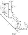
- Figure 1 shows an enteral feeding system 60 including a vented enteral reflux collection syringe 80 according to an example form of the invention.
- the enteral feeding system 60 comprises an enteral feeding container or bag 62, a plurality of tubes 64, 68, and 69, and a Y-connector or coupling 66.
- the feeding bag 62 intended for containing the nutrients/medications to be supplied to the patient, optionally includes a removably accessible opening 58 and an outlet port 59.
- the outlet port 59 is sized to receive a proximal end 61 of an administration tube 64.
- a distal end 63 of the administration tube inserts into a first arm 66a of the connector 66.
- a proximal end 65 of a gastric relief tube 69 inserts into an arm segment 66b of the connector 66, and a proximal end 67 of an enteral feeding tube 68 inserts into an arm segment 66c of the connector.
- a distal end 71 of the gastric relief tube 69 connects to the enteral reflux collection syringe 80, which is preferably supported at a higher elevation than the connector 66 and higher than the discharge of the feeding bag 62, for example the discharge port 59.
- the enteral feeding tube 68 connected to the arm segment 16c of connector 66, further comprises a distal end 70 to provide interaction with a user and is preferably at an elevation above connector 66 and below the collection system 80.
- the standard flow direction of nutrients through the feeding system is indicated by arrows A, B, BB, and C .
- the nutrients contained in the feeding bag 62 flow in the A direction through the administration tube 64.
- the nutrients enter the connector 66 through connector arm 66a and continue towards the proximal end 70 of enteral feeding tube 68 indicated by a direction arrow B, and are delivered to the digestive tract of the subject.
- the nutrients may flow back through the proximal end 70 in the opposing direction BB, and through reflux tube 69 for collection in the reflux collection syringe 80, as indicated by direction arrow C.
- the enteral feeding system of the present invention can comprise an enteral syringe used in place of the feeding bag.
- the enteral syringe can be vented to allow gravity feed by removing the plunger from the syringe body or placement of the plunger in the vent position within the syringe barrel.
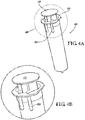
- FIGS 2 - 4 show a vented reflux collection syringe 80, according to an example form, in greater detail.
- U.S. Patent Application Serial No. 13/231,185 and U.S. Provisional Patent Application Serial No. 61/418,963 give further details of an example form of syringe construction.
- the vented reflux collection syringe 80 includes an elongated syringe body 20 and a plunger 40.
- the syringe body 20 defines an internal elongate cavity 22 that extends substantially along the length of the body from a proximal end 26 towards distal end 24.
- the distal end 24 of the syringe body 20 comprises a nozzle or tip 28 with a discharge lumen in fluid communication with the internal elongate cavity 22.
- the tip 28 of the syringe body 20 is preferably adapted for connection to the distal end 71 of the gastric relief tube 69 (as depicted in Figure 1 ).
- the proximal end 26 of the syringe body 20 includes an opening 30 for receiving the plunger 40 therein.
- the syringe is a 100mL syringe.
- the syringe body 20 can have a substantially circular cross-section or can comprise a non-circular, oval, elliptical, rectangular, or asymmetric cross-section as desired.
- the plunger 40 includes an elongated body 41 sized to be inserted into the opening 30 of the syringe body 20, the body or arm having a distal end 42 and a proximal end 44.
- the distal end 42 comprises a sealing head 45 for tightly engaging an inner wall of the body cavity 22.
- the sealing head and/or gasket 45 substantially mirrors the cross-section and diameter of the cavity 22 to provide an appropriate seal between the head and the cavity.
- the sealing head 45 frictionally engages the inner wall of the cavity 22, such that the plunger 40 remains in a particular position within the syringe body 20 absent user manipulation.
- the plunger body 41 also comprises at least one, and preferably two or more ribs 47 that extend to fit within the cross-section and/or diameter of the cavity 22.
- the ribs 47 operate to keep the plunger 40 aligned within the cavity 22 and prevent the plunger from tipping within the same.
- the ribs 47 help maintain an adequate seal between the plunger head 45 and the wall of the cavity 22.
- the proximal end 44 the plunger 40 includes a contact face 48 to permit user manipulation.
- the syringe body may include one or more vents 50.
- the vents 50 permit the passage of air into the syringe body cavity 22 when in use.
- each vent 50 comprises a channel 52 that extends from the proximal end 26 of the syringe barrel along a portion of the barrel's length, into the inner cavity 22 of the syringe body 20. While example depicted embodiments depict four vents 50, alternative embodiments can include one vent, two vents, three vents, or five or more vents as desired.
- the syringe plunger is selectively positionable within the barrel in one or more closed / unvented positions ( Figures. 2 , 3A and 4 ) where the contained volume within the syringe is sealed to prevent air passage in or out, or one or more open / vented positions ( Figure 3B ) wherein air can pass in and out of the syringe.
- the enteral reflux collection system 60 comprises one or more food-grade plastics (i.e. polypropylene), other polymers, glass, metals, metal alloys, resins, rubbers, rubber derivatives, elastomerics (i.e. santoprene), silicones or other materials of construction.
- food-grade plastics i.e. polypropylene
- other polymers i.e. polypropylene
- glass metals, metal alloys, resins, rubbers, rubber derivatives, elastomerics (i.e. santoprene), silicones or other materials of construction.
- elastomerics i.e. santoprene
- silicones or other materials of construction.
- colorants and/or other additives may be included.
- the syringe can include external markings or other indicia, for example to indicate volume capacity and/or content levels.
- the collection system 60 of the present invention can be used to deliver fluids to a subject, and to selectively collect, prevent collection, and/or induce aspiration of the gastric reflux fluids during enteral feeding.
- the plunger 40 can be positioned within the syringe body 20 in a closed position.
- the plunger 40 can be moved further into the syringe body 20 where as the plunger head 45 is advanced or retracted, increased pressure or suction alternatively develops to alleviate a clog within the reflux tube.
- the collection of gastric fluids is enabled by positioning the syringe in its vented state as shown in Figure 3B .
- the enteral reflux collection system 80 of the present invention is multi-functional, selectively providing ventilation, vacuum, and/or suction.
Landscapes
- Health & Medical Sciences (AREA)
- Public Health (AREA)
- Life Sciences & Earth Sciences (AREA)
- Animal Behavior & Ethology (AREA)
- General Health & Medical Sciences (AREA)
- Veterinary Medicine (AREA)
- Anesthesiology (AREA)
- Biomedical Technology (AREA)
- Heart & Thoracic Surgery (AREA)
- Hematology (AREA)
- Engineering & Computer Science (AREA)
- Vascular Medicine (AREA)
- Infusion, Injection, And Reservoir Apparatuses (AREA)
Description
- This application claims the priority benefit of
U.S. Provisional Patent Application Serial No. 61/549,308 filed October 20, 2011 U.S. Patent Application Serial No. 13/231,185 filed September 13, 2011 U.S. Provisional Patent Application Serial No. 61/418,963 filed December 2, 2010 - The present invention relates generally to the field of enteral nutrition, and more particularly to an improved system for relieving gastric pressure in a human or animal patient during enteral feeding.
- Enteral feeding systems are generally utilized to supply nutrition to the human gastrointestinal tract through an enteral feeding tube. For example, in the field of enteral feeding systems, optional delivery methods can include an enteral pump, syringe pump, or gravity feed delivery system. Optionally, a gastric pressure relief system can be used in conjunction with enteral feeding systems, for example when the subject is susceptible to reflux.
- The gastric pressure relief system generally comprises a gastric reflux container, usually a vented disposable bag suspended above the stomach of the user, providing a reservoir for reflux gas and fluids to collect. The relief system can include an inlet/outlet port comprising a length of relief tubing that connects to the enteral feeding system. When administering nutrients to a user, the gastric reflux stomach contents intended to collect in the relief system can obtain trapped air pockets or gas bubbles clogging the relief tube. The stomach contents prevent further reflux to flow in the relief system and require disconnecting and cleaning the relief tube. The removal of the relief system from the enteral feeding system is often seen as a drawback to enteral administration and can severely alter the users feeding regimen. Additionally, undergoing an alteration mid-feeding can potentially waste much needed nutrients.
-
US 5 460 603 discloses an apparatus for providing liquid to a patient, preventing reflux and permitting venting. Tubes or other suitable apparatus are provided for connecting to the liquid source and the patient. An anti-reflux valve is provided in the hydraulic channel between the source and the patient. A vent is provided in the channel between the anti-reflux valve and the patient. Thus, gas urged from the patient under pressure is urged out of the vent. However, liquid similarly urged from the patient is prevented from overflowing by the anti-reflux valve. In a preferred embodiment, the anti-reflux valve is a flapper valve or a ball valve. In another preferred embodiment, the vent is a gas permeable, liquid impervious fabric. Alternatively, the vent may be a float valve. The apparatus is useful for gastroenterological feeding, nasogastric feeding and the like. -
DE 296 17 949 discloses a syringe with a syringe body and ventilation channel or gap at the entrance of the syringe body. The ventilation gap allows a capillary tube to be inserted into the syringe body in order to take samples of the blood after the syringe has been removed from the patient. -
WO 2012/037082 (published 22.03.2012 ) discloses an enteral syringe that can include an elongated body having a hollow cavity therein and at least one vent extending from the hollow cavity to an outside surface of the syringe body. The elongated body can have a first non-circular cross-section. The enteral syringe can also have a plunger operable to selectively travel within the hollow cavity. The plunger can additionally have a second non-circular cross-section that substantially mirrors the first non-circular cross-section. The enteral syringe can additionally have at least one support feature for hanging the syringe from a support structure. - It is to the provision of an improved system for enteral gastric pressure relief and collection meeting these and other needs that the present invention is primarily directed.
- The invention is defined in the attached independent claim to which reference should now be made. Further, optional features may be found in the sub-claims appended thereto.
- In example embodiments, the present invention selectively provides ventilation, vacuum and suction within the reflux collection system during use. The reflux collection system of the present invention can be utilized with the administration of various types of fluids to patients, such as medications, nutrients, food, water, etc. In particular, it has been found that the reflux collection system of the present invention greatly improves the administration of nutrients and/or medications when used in conjunction with pump, syringe pump, or gravity-fed enteral feeding systems. The present invention relates to an enteral reflux collection system for use with an enteral fluid container comprising a discharge and a feeding tube, the enteral reflux collection system comprising: a gastric reflux collection syringe comprising a confined internal cavity and a plunger; and a reflux relief tube to deliver gastric reflux to the gastric reflux collection syringe, the reflux relief tube coupled with respect to the feeding tube.
- Described is also an enteral reflux collection system having a fluid container with a discharge. The system also has an enteral feeding tube for delivering fluid from the fluid container and a vented reflux collection syringe. The system also has a reflux relief tube for delivering reflux to the vented reflux syringe. The reflux relief tube is coupled with respect to the enteral feeding tube.
- Further is described a method for enteral fluid delivery, the method including the steps of delivering a fluid from a container to an enteral feeding tube, and selectively positioning a vented reflux collection syringe to alternatively permit or prevent gastric reflux collection within the syringe, or to aspirate fluid through one or more associated fluid delivery tubes.
- These and other aspects, features and advantages of the invention will be understood with reference to the drawing figures and detailed description herein, and will be realized by means of the various elements and combinations particularly pointed out in the appended claims. It is to be understood that both the foregoing general description and the following brief description of the drawings and detailed description of the invention are exemplary and explanatory of preferred embodiments of the invention, and are not restrictive of the invention, which is defined in the claims.
-
-
FIGURE 1 shows an enteral reflux collection system according to a first example embodiment of the present invention incorporated with an enteral feeding system. -
FIGURES 2A - 2F show a vented syringe suited for use in connection with the system of the present invention according to an example form. -
FIGURES 3A and 3B show cross-sectional views of the vented syringe ofFIG 2 . -
FIGURES 4A and 4B show perspective views of the vented syringe ofFIG 2 . - The present invention may be understood more readily by reference to the following detailed description of the invention taken in connection with the accompanying drawing figures, which form a part of this disclosure. It is to be understood that this invention is not limited to the specific devices, conditions or parameters described and/or shown herein, and that the terminology used herein is for the purpose of describing particular embodiments by way of example only and is not intended to be limiting of the claimed invention.
- With reference now to the drawing figures,
Figure 1 shows anenteral feeding system 60 including a vented enteralreflux collection syringe 80 according to an example form of the invention. In general, theenteral feeding system 60 comprises an enteral feeding container or bag 62, a plurality oftubes coupling 66. The feeding bag 62, intended for containing the nutrients/medications to be supplied to the patient, optionally includes a removablyaccessible opening 58 and anoutlet port 59. Theoutlet port 59 is sized to receive aproximal end 61 of anadministration tube 64. Adistal end 63 of the administration tube inserts into afirst arm 66a of theconnector 66. Aproximal end 65 of agastric relief tube 69 inserts into an arm segment 66b of theconnector 66, and aproximal end 67 of an enteral feeding tube 68 inserts into anarm segment 66c of the connector. Adistal end 71 of thegastric relief tube 69 connects to the enteralreflux collection syringe 80, which is preferably supported at a higher elevation than theconnector 66 and higher than the discharge of the feeding bag 62, for example thedischarge port 59. The enteral feeding tube 68, connected to the arm segment 16c ofconnector 66, further comprises adistal end 70 to provide interaction with a user and is preferably at an elevation aboveconnector 66 and below thecollection system 80. - The standard flow direction of nutrients through the feeding system is indicated by arrows A, B, BB, and C. The nutrients contained in the feeding bag 62 flow in the A direction through the
administration tube 64. The nutrients enter theconnector 66 throughconnector arm 66a and continue towards theproximal end 70 of enteral feeding tube 68 indicated by a direction arrow B, and are delivered to the digestive tract of the subject. In the event of gastric reflux from the subject, the nutrients may flow back through theproximal end 70 in the opposing direction BB, and throughreflux tube 69 for collection in thereflux collection syringe 80, as indicated by direction arrow C. In alternate embodiments, the enteral feeding system of the present invention can comprise an enteral syringe used in place of the feeding bag. The enteral syringe can be vented to allow gravity feed by removing the plunger from the syringe body or placement of the plunger in the vent position within the syringe barrel. -
Figures 2 - 4 show a ventedreflux collection syringe 80, according to an example form, in greater detail.U.S. Patent Application Serial No. 13/231,185 andU.S. Provisional Patent Application Serial No. 61/418,963 reflux collection syringe 80 includes anelongated syringe body 20 and aplunger 40. Thesyringe body 20 defines an internalelongate cavity 22 that extends substantially along the length of the body from aproximal end 26 towardsdistal end 24. Thedistal end 24 of thesyringe body 20 comprises a nozzle ortip 28 with a discharge lumen in fluid communication with the internalelongate cavity 22. Thetip 28 of thesyringe body 20 is preferably adapted for connection to thedistal end 71 of the gastric relief tube 69 (as depicted inFigure 1 ). Theproximal end 26 of thesyringe body 20 includes anopening 30 for receiving theplunger 40 therein. In an example embodiment, the syringe is a 100mL syringe. Thesyringe body 20 can have a substantially circular cross-section or can comprise a non-circular, oval, elliptical, rectangular, or asymmetric cross-section as desired. - The
plunger 40 includes an elongated body 41 sized to be inserted into theopening 30 of thesyringe body 20, the body or arm having adistal end 42 and aproximal end 44. Thedistal end 42 comprises a sealinghead 45 for tightly engaging an inner wall of thebody cavity 22. The sealing head and/orgasket 45 substantially mirrors the cross-section and diameter of thecavity 22 to provide an appropriate seal between the head and the cavity. In example embodiments, the sealinghead 45 frictionally engages the inner wall of thecavity 22, such that theplunger 40 remains in a particular position within thesyringe body 20 absent user manipulation. The plunger body 41 also comprises at least one, and preferably two ormore ribs 47 that extend to fit within the cross-section and/or diameter of thecavity 22. Thus, as theplunger 40 is selectively inserted into thecavity 22 of thesyringe body 20 and travels therein during use, theribs 47 operate to keep theplunger 40 aligned within thecavity 22 and prevent the plunger from tipping within the same. As such, theribs 47 help maintain an adequate seal between theplunger head 45 and the wall of thecavity 22. Theproximal end 44 theplunger 40 includes acontact face 48 to permit user manipulation. - In order to permit the enteral
reflux collection syringe 80 of the present invention to be vented during use (without fully removing theplunger 40 from the syringe body 20), the syringe body may include one or more vents 50. Thevents 50 permit the passage of air into thesyringe body cavity 22 when in use. In the depicted example embodiments, eachvent 50 comprises achannel 52 that extends from theproximal end 26 of the syringe barrel along a portion of the barrel's length, into theinner cavity 22 of thesyringe body 20. While example depicted embodiments depict fourvents 50, alternative embodiments can include one vent, two vents, three vents, or five or more vents as desired. The syringe plunger is selectively positionable within the barrel in one or more closed / unvented positions (Figures. 2 ,3A and4 ) where the contained volume within the syringe is sealed to prevent air passage in or out, or one or more open / vented positions (Figure 3B ) wherein air can pass in and out of the syringe. - In example embodiments, the enteral
reflux collection system 60 comprises one or more food-grade plastics (i.e. polypropylene), other polymers, glass, metals, metal alloys, resins, rubbers, rubber derivatives, elastomerics (i.e. santoprene), silicones or other materials of construction. Optionally, colorants and/or other additives may be included. The syringe can include external markings or other indicia, for example to indicate volume capacity and/or content levels. - In operation, the
collection system 60 of the present invention can be used to deliver fluids to a subject, and to selectively collect, prevent collection, and/or induce aspiration of the gastric reflux fluids during enteral feeding. For preventing the collection of gastric reflux fluids, as shown inFigure 3A , theplunger 40 can be positioned within thesyringe body 20 in a closed position. Alternately, for inducing aspiration of gastric fluids, theplunger 40 can be moved further into thesyringe body 20 where as theplunger head 45 is advanced or retracted, increased pressure or suction alternatively develops to alleviate a clog within the reflux tube. Additionally, the collection of gastric fluids is enabled by positioning the syringe in its vented state as shown inFigure 3B . As a result, the enteralreflux collection system 80 of the present invention is multi-functional, selectively providing ventilation, vacuum, and/or suction. - While the invention has been described with reference to preferred and example embodiments, it will be understood by those skilled in the art that a variety of modifications, additions and deletions are within the scope of the invention, as defined by the following claims.
Claims (8)
- An enteral reflux collection system for use with an enteral fluid container (62) comprising a discharge (59) and a feeding tube (68), the enteral reflux collection system characterized by comprising:a gastric reflux collection syringe (80) comprising a confined internal cavity (22) and a plunger (40); anda reflux relief tube (69) to deliver gastric reflux to the gastric reflux collection syringe (80), the reflux relief tube (69) coupled with respect to the feeding tube (68).
- The enteral reflux collection system of Claim 1, wherein the gastric reflux collection syringe plunger (40) comprises a gasket (45) configured to translatably manipulate a releasable vacuum within the confined internal cavity (22).
- The enteral reflux collection system of Claim 2, wherein the gastric reflux collection syringe (80) is configured to achieve optimal performance when positioned at a higher elevation than the enteral fluid container discharge (59).
- The enteral reflux collection system of Claim 1, wherein the gastric reflux collection syringe (80) comprises at least one vent (50).
- The enteral reflux collection system of Claim 4, wherein the at least one vent (50) comprises an elongated channel (52) extending a predetermined length along the confined internal cavity (22).
- The enteral reflux collection system of Claim 5, wherein the plunger (40) comprises a sealing head (45), the sealing head (45) being translatably configured to manipulate a releasable vacuum within the confined internal cavity (22).
- The enteral reflux collection system of Claim 6, wherein the vacuum is configured to be released when the sealing head (45) is aligned with the at least one vent (50).
- The enteral reflux collection system of any of claims 1-5, wherein the gastric reflux collection syringe (80) comprises a syringe body (20) having a confined internal cavity (22) and a plunger (40) having a sealing head (45), the sealing head (45) being translatably configured to manipulate a releasable vacuum within the confined internal cavity (22), and wherein the plunger (40) is configured to be removed from the syringe body (20) to release the vacuum.
Applications Claiming Priority (3)
| Application Number | Priority Date | Filing Date | Title |
|---|---|---|---|
| US201161549308P | 2011-10-20 | 2011-10-20 | |
| PCT/US2012/060987 WO2013059571A1 (en) | 2011-10-20 | 2012-10-19 | Enteral feeding and reflux collection system and method using vented syringe |
| EP12788678.6A EP2768557B1 (en) | 2011-10-20 | 2012-10-19 | Enteral feeding and reflux collection system and method using vented syringe |
Related Parent Applications (2)
| Application Number | Title | Priority Date | Filing Date |
|---|---|---|---|
| EP12788678.6A Division EP2768557B1 (en) | 2011-10-20 | 2012-10-19 | Enteral feeding and reflux collection system and method using vented syringe |
| EP12788678.6A Division-Into EP2768557B1 (en) | 2011-10-20 | 2012-10-19 | Enteral feeding and reflux collection system and method using vented syringe |
Publications (2)
| Publication Number | Publication Date |
|---|---|
| EP2944342A1 EP2944342A1 (en) | 2015-11-18 |
| EP2944342B1 true EP2944342B1 (en) | 2018-08-22 |
Family
ID=47216405
Family Applications (2)
| Application Number | Title | Priority Date | Filing Date |
|---|---|---|---|
| EP15173891.1A Active EP2944342B1 (en) | 2011-10-20 | 2012-10-19 | Enteral feeding and reflux collection system |
| EP12788678.6A Active EP2768557B1 (en) | 2011-10-20 | 2012-10-19 | Enteral feeding and reflux collection system and method using vented syringe |
Family Applications After (1)
| Application Number | Title | Priority Date | Filing Date |
|---|---|---|---|
| EP12788678.6A Active EP2768557B1 (en) | 2011-10-20 | 2012-10-19 | Enteral feeding and reflux collection system and method using vented syringe |
Country Status (4)
| Country | Link |
|---|---|
| US (1) | US9028438B2 (en) |
| EP (2) | EP2944342B1 (en) |
| CA (1) | CA2852931C (en) |
| WO (1) | WO2013059571A1 (en) |
Families Citing this family (14)
| Publication number | Priority date | Publication date | Assignee | Title |
|---|---|---|---|---|
| US9283148B2 (en) | 2011-03-07 | 2016-03-15 | Medela Holding Ag | Multi-purpose syringe |
| JP6865161B2 (en) * | 2014-09-04 | 2021-04-28 | コーパック メドシステムズ インコーポレイテッド | Gastric systems, devices and methods for use with enteral nutrition |
| USD784520S1 (en) | 2015-09-04 | 2017-04-18 | Corpak Medsystems, Inc. | Gastric material collection bag |
| USD784521S1 (en) | 2015-09-04 | 2017-04-18 | Corpak Medsystems, Inc. | Gastric material collection bag |
| USD784519S1 (en) | 2015-09-04 | 2017-04-18 | Corpak Medsystems, Inc. | Gastric material collection bag |
| USD785165S1 (en) | 2015-09-04 | 2017-04-25 | Corpak Medsystems, Inc. | Gastric material collection bag |
| EP3743152A1 (en) | 2018-01-23 | 2020-12-02 | Neomed, Inc. | Vented air release coupling and method of using the same |
| CN108310480A (en) * | 2018-02-07 | 2018-07-24 | 苏州元禾医疗器械有限公司 | A kind of Wound treating equipment liquid level controlling method |
| WO2019213344A1 (en) * | 2018-05-02 | 2019-11-07 | Virginia Commonwealth University | Tubie vent gastrostomy venting unit |
| US11266574B2 (en) * | 2018-08-27 | 2022-03-08 | Avent, Inc. | Blenderized diet and/or bolus delivery manual pump |
| CN109498902A (en) * | 2018-12-24 | 2019-03-22 | 南通市第人民医院 | A kind of transfusion control system |
| CN111840091A (en) * | 2020-08-20 | 2020-10-30 | 海南医学院 | Manual formula nasogastric tube feeds and eats device |
| CN113827853B (en) * | 2021-10-15 | 2024-01-26 | 谢雨亭 | Gastroenterology medicine directly gives formula intestines and stomach ware of dosing |
| CN114470496B (en) * | 2022-01-14 | 2024-04-12 | 赵子逸 | Nasal and olfactory region circulation drug delivery device |
Family Cites Families (21)
| Publication number | Priority date | Publication date | Assignee | Title |
|---|---|---|---|---|
| US4356824A (en) | 1980-07-30 | 1982-11-02 | Vazquez Richard M | Multiple lumen gastrostomy tube |
| US4392851A (en) | 1981-11-23 | 1983-07-12 | Abbott Laboratories | In-line transfer unit |
| DE4032761A1 (en) | 1990-10-16 | 1992-04-23 | Schuckmann Alfred Von | CARTRIDGE FOR USE IN DISPENSER |
| US5460603A (en) * | 1993-04-08 | 1995-10-24 | Massachusetts Institute Of Technology | Method and apparatus for preventing back flow in gastroenterological feeding system |
| US5611787A (en) * | 1994-10-13 | 1997-03-18 | Methodist Hospital Of Indiana, Inc. | Method and device for gastric line insertion |
| DE29617949U1 (en) * | 1996-10-01 | 1997-04-30 | Schulz, Klaus, Dr.med., 50259 Pulheim | Syringe with a closable venting channel or venting gap |
| US6482170B1 (en) * | 2000-09-18 | 2002-11-19 | Corpak, Inc. | Apparatus and method for relieving gastric pressure during enteral feeding |
| US20040054350A1 (en) | 2002-09-17 | 2004-03-18 | Shaughnessy Michael C. | Enteral feeding unit having a reflux device and reflux method |
| US7174923B2 (en) * | 2003-10-31 | 2007-02-13 | Codman & Shurtleff, Inc. | Refill kit for an implantable pump |
| DE102004023078B3 (en) | 2004-05-11 | 2006-01-19 | Fresenius Kabi Deutschland Gmbh | Probe for enteral nutrition and probe system for enteral nutrition and gastric decompression or drainage |
| WO2007095541A2 (en) * | 2006-02-13 | 2007-08-23 | Gerald Moss | Plural lumen gastrostomy tube insert for placement into the duodenum and method of monitoring and managing feeding |
| US7842217B2 (en) | 2007-03-28 | 2010-11-30 | Benlan, Inc. | Enteral-only syringe and method of manufacturing same |
| US8162916B2 (en) | 2008-02-08 | 2012-04-24 | Codan Us Corporation | Enteral feeding safety reservoir and system |
| US8366697B2 (en) | 2008-02-08 | 2013-02-05 | Codan Us Corporation | Enteral feeding safety reservoir and system |
| US8231597B2 (en) | 2008-02-08 | 2012-07-31 | Codan Us Corporation | Enteral feeding safety reservoir and system |
| WO2009141510A1 (en) | 2008-05-20 | 2009-11-26 | Sannier Gerard | Gel dispenser |
| US20110270227A1 (en) | 2010-04-30 | 2011-11-03 | Baxa Corporation | Method and apparatus for the enteral dispensation of liquid medications |
| US9433562B2 (en) | 2010-07-27 | 2016-09-06 | Neomed, Inc. | System for aseptic collection and enteral delivery |
| CA2809636C (en) * | 2010-09-14 | 2016-07-26 | Neomed, Inc. | Enteral syringe |
| US8777900B2 (en) | 2010-12-14 | 2014-07-15 | Kimberly-Clark Worldwide, Inc. | Ambulatory enteral feeding system |
| US20120150111A1 (en) | 2010-12-14 | 2012-06-14 | Hershey Adrienne A | Passive Enteral Venting System |
-
2012
- 2012-10-19 CA CA2852931A patent/CA2852931C/en active Active
- 2012-10-19 EP EP15173891.1A patent/EP2944342B1/en active Active
- 2012-10-19 EP EP12788678.6A patent/EP2768557B1/en active Active
- 2012-10-19 WO PCT/US2012/060987 patent/WO2013059571A1/en active Application Filing
- 2012-10-19 US US13/655,780 patent/US9028438B2/en active Active
Non-Patent Citations (1)
| Title |
|---|
| None * |
Also Published As
| Publication number | Publication date |
|---|---|
| WO2013059571A1 (en) | 2013-04-25 |
| EP2944342A1 (en) | 2015-11-18 |
| EP2768557A1 (en) | 2014-08-27 |
| CA2852931C (en) | 2016-10-11 |
| EP2768557B1 (en) | 2015-08-26 |
| US20130066260A1 (en) | 2013-03-14 |
| CA2852931A1 (en) | 2013-04-25 |
| US9028438B2 (en) | 2015-05-12 |
Similar Documents
| Publication | Publication Date | Title |
|---|---|---|
| EP2944342B1 (en) | Enteral feeding and reflux collection system | |
| US7470265B2 (en) | Dual access spike for infusate bags | |
| CN108136170B (en) | Dual port tubing for suction and feeding systems, methods and devices | |
| US20030153897A1 (en) | Closed system drainage and infusion connector valve | |
| US9757522B2 (en) | Enteral syringe | |
| TW201124179A (en) | Tubing set having a gate for the connection of vials | |
| JP4332432B2 (en) | Dosage container used for indwelling administration | |
| WO2007095541A2 (en) | Plural lumen gastrostomy tube insert for placement into the duodenum and method of monitoring and managing feeding | |
| US20120283627A1 (en) | Method for combined gastrointestional feeding and aspiration | |
| US9433729B2 (en) | Enteral syringe | |
| US20030195482A1 (en) | Pneumatic medical system | |
| CA2929979C (en) | Enteral syringe | |
| CN112351805B (en) | Enteral syringe with venting collar | |
| CN113144311A (en) | Sputum suction and drug administration integrated device for department of respiration and use method thereof | |
| CN101327347B (en) | Disposal coloclysis administration dialyser | |
| CN215022612U (en) | Gastroenterology nursing is fed with liquid food and is eaten device | |
| CN203227045U (en) | Stomach tube capable of preventing stomach flatulence | |
| CN209422621U (en) | Anal tube for enema administration | |
| CN2691611Y (en) | Three purpose discharging adding transfusion system | |
| WO2018166936A1 (en) | Closed enteral feeding system for drainage of gastric fluid |
Legal Events
| Date | Code | Title | Description |
|---|---|---|---|
| PUAI | Public reference made under article 153(3) epc to a published international application that has entered the european phase |
Free format text: ORIGINAL CODE: 0009012 |
|
| AC | Divisional application: reference to earlier application |
Ref document number: 2768557 Country of ref document: EP Kind code of ref document: P |
|
| AK | Designated contracting states |
Kind code of ref document: A1 Designated state(s): AL AT BE BG CH CY CZ DE DK EE ES FI FR GB GR HR HU IE IS IT LI LT LU LV MC MK MT NL NO PL PT RO RS SE SI SK SM TR |
|
| 17P | Request for examination filed |
Effective date: 20160125 |
|
| RBV | Designated contracting states (corrected) |
Designated state(s): AL AT BE BG CH CY CZ DE DK EE ES FI FR GB GR HR HU IE IS IT LI LT LU LV MC MK MT NL NO PL PT RO RS SE SI SK SM TR |
|
| STAA | Information on the status of an ep patent application or granted ep patent |
Free format text: STATUS: EXAMINATION IS IN PROGRESS |
|
| 17Q | First examination report despatched |
Effective date: 20170818 |
|
| GRAP | Despatch of communication of intention to grant a patent |
Free format text: ORIGINAL CODE: EPIDOSNIGR1 |
|
| STAA | Information on the status of an ep patent application or granted ep patent |
Free format text: STATUS: GRANT OF PATENT IS INTENDED |
|
| INTG | Intention to grant announced |
Effective date: 20180313 |
|
| GRAS | Grant fee paid |
Free format text: ORIGINAL CODE: EPIDOSNIGR3 |
|
| GRAA | (expected) grant |
Free format text: ORIGINAL CODE: 0009210 |
|
| STAA | Information on the status of an ep patent application or granted ep patent |
Free format text: STATUS: THE PATENT HAS BEEN GRANTED |
|
| AC | Divisional application: reference to earlier application |
Ref document number: 2768557 Country of ref document: EP Kind code of ref document: P |
|
| AK | Designated contracting states |
Kind code of ref document: B1 Designated state(s): AL AT BE BG CH CY CZ DE DK EE ES FI FR GB GR HR HU IE IS IT LI LT LU LV MC MK MT NL NO PL PT RO RS SE SI SK SM TR |
|
| REG | Reference to a national code |
Ref country code: GB Ref legal event code: FG4D |
|
| REG | Reference to a national code |
Ref country code: CH Ref legal event code: EP |
|
| REG | Reference to a national code |
Ref country code: AT Ref legal event code: REF Ref document number: 1031733 Country of ref document: AT Kind code of ref document: T Effective date: 20180915 |
|
| REG | Reference to a national code |
Ref country code: IE Ref legal event code: FG4D |
|
| REG | Reference to a national code |
Ref country code: DE Ref legal event code: R096 Ref document number: 602012050287 Country of ref document: DE |
|
| REG | Reference to a national code |
Ref country code: FR Ref legal event code: PLFP Year of fee payment: 7 |
|
| REG | Reference to a national code |
Ref country code: NL Ref legal event code: MP Effective date: 20180822 |
|
| REG | Reference to a national code |
Ref country code: LT Ref legal event code: MG4D |
|
| PG25 | Lapsed in a contracting state [announced via postgrant information from national office to epo] |
Ref country code: LT Free format text: LAPSE BECAUSE OF FAILURE TO SUBMIT A TRANSLATION OF THE DESCRIPTION OR TO PAY THE FEE WITHIN THE PRESCRIBED TIME-LIMIT Effective date: 20180822 Ref country code: IS Free format text: LAPSE BECAUSE OF FAILURE TO SUBMIT A TRANSLATION OF THE DESCRIPTION OR TO PAY THE FEE WITHIN THE PRESCRIBED TIME-LIMIT Effective date: 20181222 Ref country code: BG Free format text: LAPSE BECAUSE OF FAILURE TO SUBMIT A TRANSLATION OF THE DESCRIPTION OR TO PAY THE FEE WITHIN THE PRESCRIBED TIME-LIMIT Effective date: 20181122 Ref country code: NL Free format text: LAPSE BECAUSE OF FAILURE TO SUBMIT A TRANSLATION OF THE DESCRIPTION OR TO PAY THE FEE WITHIN THE PRESCRIBED TIME-LIMIT Effective date: 20180822 Ref country code: SE Free format text: LAPSE BECAUSE OF FAILURE TO SUBMIT A TRANSLATION OF THE DESCRIPTION OR TO PAY THE FEE WITHIN THE PRESCRIBED TIME-LIMIT Effective date: 20180822 Ref country code: NO Free format text: LAPSE BECAUSE OF FAILURE TO SUBMIT A TRANSLATION OF THE DESCRIPTION OR TO PAY THE FEE WITHIN THE PRESCRIBED TIME-LIMIT Effective date: 20181122 Ref country code: GR Free format text: LAPSE BECAUSE OF FAILURE TO SUBMIT A TRANSLATION OF THE DESCRIPTION OR TO PAY THE FEE WITHIN THE PRESCRIBED TIME-LIMIT Effective date: 20181123 Ref country code: RS Free format text: LAPSE BECAUSE OF FAILURE TO SUBMIT A TRANSLATION OF THE DESCRIPTION OR TO PAY THE FEE WITHIN THE PRESCRIBED TIME-LIMIT Effective date: 20180822 Ref country code: FI Free format text: LAPSE BECAUSE OF FAILURE TO SUBMIT A TRANSLATION OF THE DESCRIPTION OR TO PAY THE FEE WITHIN THE PRESCRIBED TIME-LIMIT Effective date: 20180822 |
|
| REG | Reference to a national code |
Ref country code: AT Ref legal event code: MK05 Ref document number: 1031733 Country of ref document: AT Kind code of ref document: T Effective date: 20180822 |
|
| PG25 | Lapsed in a contracting state [announced via postgrant information from national office to epo] |
Ref country code: AL Free format text: LAPSE BECAUSE OF FAILURE TO SUBMIT A TRANSLATION OF THE DESCRIPTION OR TO PAY THE FEE WITHIN THE PRESCRIBED TIME-LIMIT Effective date: 20180822 Ref country code: LV Free format text: LAPSE BECAUSE OF FAILURE TO SUBMIT A TRANSLATION OF THE DESCRIPTION OR TO PAY THE FEE WITHIN THE PRESCRIBED TIME-LIMIT Effective date: 20180822 Ref country code: HR Free format text: LAPSE BECAUSE OF FAILURE TO SUBMIT A TRANSLATION OF THE DESCRIPTION OR TO PAY THE FEE WITHIN THE PRESCRIBED TIME-LIMIT Effective date: 20180822 |
|
| PG25 | Lapsed in a contracting state [announced via postgrant information from national office to epo] |
Ref country code: CZ Free format text: LAPSE BECAUSE OF FAILURE TO SUBMIT A TRANSLATION OF THE DESCRIPTION OR TO PAY THE FEE WITHIN THE PRESCRIBED TIME-LIMIT Effective date: 20180822 Ref country code: RO Free format text: LAPSE BECAUSE OF FAILURE TO SUBMIT A TRANSLATION OF THE DESCRIPTION OR TO PAY THE FEE WITHIN THE PRESCRIBED TIME-LIMIT Effective date: 20180822 Ref country code: IT Free format text: LAPSE BECAUSE OF FAILURE TO SUBMIT A TRANSLATION OF THE DESCRIPTION OR TO PAY THE FEE WITHIN THE PRESCRIBED TIME-LIMIT Effective date: 20180822 Ref country code: PL Free format text: LAPSE BECAUSE OF FAILURE TO SUBMIT A TRANSLATION OF THE DESCRIPTION OR TO PAY THE FEE WITHIN THE PRESCRIBED TIME-LIMIT Effective date: 20180822 Ref country code: EE Free format text: LAPSE BECAUSE OF FAILURE TO SUBMIT A TRANSLATION OF THE DESCRIPTION OR TO PAY THE FEE WITHIN THE PRESCRIBED TIME-LIMIT Effective date: 20180822 Ref country code: AT Free format text: LAPSE BECAUSE OF FAILURE TO SUBMIT A TRANSLATION OF THE DESCRIPTION OR TO PAY THE FEE WITHIN THE PRESCRIBED TIME-LIMIT Effective date: 20180822 Ref country code: ES Free format text: LAPSE BECAUSE OF FAILURE TO SUBMIT A TRANSLATION OF THE DESCRIPTION OR TO PAY THE FEE WITHIN THE PRESCRIBED TIME-LIMIT Effective date: 20180822 |
|
| REG | Reference to a national code |
Ref country code: DE Ref legal event code: R097 Ref document number: 602012050287 Country of ref document: DE |
|
| PG25 | Lapsed in a contracting state [announced via postgrant information from national office to epo] |
Ref country code: SK Free format text: LAPSE BECAUSE OF FAILURE TO SUBMIT A TRANSLATION OF THE DESCRIPTION OR TO PAY THE FEE WITHIN THE PRESCRIBED TIME-LIMIT Effective date: 20180822 Ref country code: SM Free format text: LAPSE BECAUSE OF FAILURE TO SUBMIT A TRANSLATION OF THE DESCRIPTION OR TO PAY THE FEE WITHIN THE PRESCRIBED TIME-LIMIT Effective date: 20180822 Ref country code: DK Free format text: LAPSE BECAUSE OF FAILURE TO SUBMIT A TRANSLATION OF THE DESCRIPTION OR TO PAY THE FEE WITHIN THE PRESCRIBED TIME-LIMIT Effective date: 20180822 |
|
| REG | Reference to a national code |
Ref country code: CH Ref legal event code: PL |
|
| PG25 | Lapsed in a contracting state [announced via postgrant information from national office to epo] |
Ref country code: LU Free format text: LAPSE BECAUSE OF NON-PAYMENT OF DUE FEES Effective date: 20181019 Ref country code: MC Free format text: LAPSE BECAUSE OF FAILURE TO SUBMIT A TRANSLATION OF THE DESCRIPTION OR TO PAY THE FEE WITHIN THE PRESCRIBED TIME-LIMIT Effective date: 20180822 |
|
| PLBE | No opposition filed within time limit |
Free format text: ORIGINAL CODE: 0009261 |
|
| STAA | Information on the status of an ep patent application or granted ep patent |
Free format text: STATUS: NO OPPOSITION FILED WITHIN TIME LIMIT |
|
| 26N | No opposition filed |
Effective date: 20190523 |
|
| PG25 | Lapsed in a contracting state [announced via postgrant information from national office to epo] |
Ref country code: CH Free format text: LAPSE BECAUSE OF NON-PAYMENT OF DUE FEES Effective date: 20181031 Ref country code: LI Free format text: LAPSE BECAUSE OF NON-PAYMENT OF DUE FEES Effective date: 20181031 Ref country code: SI Free format text: LAPSE BECAUSE OF FAILURE TO SUBMIT A TRANSLATION OF THE DESCRIPTION OR TO PAY THE FEE WITHIN THE PRESCRIBED TIME-LIMIT Effective date: 20180822 |
|
| PG25 | Lapsed in a contracting state [announced via postgrant information from national office to epo] |
Ref country code: MT Free format text: LAPSE BECAUSE OF NON-PAYMENT OF DUE FEES Effective date: 20181019 |
|
| PG25 | Lapsed in a contracting state [announced via postgrant information from national office to epo] |
Ref country code: TR Free format text: LAPSE BECAUSE OF FAILURE TO SUBMIT A TRANSLATION OF THE DESCRIPTION OR TO PAY THE FEE WITHIN THE PRESCRIBED TIME-LIMIT Effective date: 20180822 |
|
| PG25 | Lapsed in a contracting state [announced via postgrant information from national office to epo] |
Ref country code: PT Free format text: LAPSE BECAUSE OF FAILURE TO SUBMIT A TRANSLATION OF THE DESCRIPTION OR TO PAY THE FEE WITHIN THE PRESCRIBED TIME-LIMIT Effective date: 20180822 |
|
| PG25 | Lapsed in a contracting state [announced via postgrant information from national office to epo] |
Ref country code: HU Free format text: LAPSE BECAUSE OF FAILURE TO SUBMIT A TRANSLATION OF THE DESCRIPTION OR TO PAY THE FEE WITHIN THE PRESCRIBED TIME-LIMIT; INVALID AB INITIO Effective date: 20121019 Ref country code: MK Free format text: LAPSE BECAUSE OF NON-PAYMENT OF DUE FEES Effective date: 20180822 Ref country code: CY Free format text: LAPSE BECAUSE OF FAILURE TO SUBMIT A TRANSLATION OF THE DESCRIPTION OR TO PAY THE FEE WITHIN THE PRESCRIBED TIME-LIMIT Effective date: 20180822 |
|
| REG | Reference to a national code |
Ref country code: DE Ref legal event code: R082 Ref document number: 602012050287 Country of ref document: DE Representative=s name: HL KEMPNER PATENTANWAELTE, SOLICITORS (ENGLAND, DE Ref country code: DE Ref legal event code: R082 Ref document number: 602012050287 Country of ref document: DE Representative=s name: HL KEMPNER PATENTANWALT, RECHTSANWALT, SOLICIT, DE |
|
| PGFP | Annual fee paid to national office [announced via postgrant information from national office to epo] |
Ref country code: IE Payment date: 20201009 Year of fee payment: 9 |
|
| PG25 | Lapsed in a contracting state [announced via postgrant information from national office to epo] |
Ref country code: IE Free format text: LAPSE BECAUSE OF NON-PAYMENT OF DUE FEES Effective date: 20211019 |
|
| P01 | Opt-out of the competence of the unified patent court (upc) registered |
Effective date: 20230518 |
|
| REG | Reference to a national code |
Ref country code: DE Ref legal event code: R081 Ref document number: 602012050287 Country of ref document: DE Owner name: AVENT INC., ALPHARETTA, US Free format text: FORMER OWNER: NEOMED, INC., WOODSTOCK, GA., US |
|
| REG | Reference to a national code |
Ref country code: GB Ref legal event code: 732E Free format text: REGISTERED BETWEEN 20230629 AND 20230705 |
|
| PGFP | Annual fee paid to national office [announced via postgrant information from national office to epo] |
Ref country code: GB Payment date: 20230831 Year of fee payment: 12 |
|
| REG | Reference to a national code |
Ref country code: BE Ref legal event code: PD Owner name: AVENT, INC.; US Free format text: DETAILS ASSIGNMENT: CHANGE OF OWNER(S), ASSIGNMENT; FORMER OWNER NAME: NEOMED, INC. Effective date: 20231003 |
|
| PGFP | Annual fee paid to national office [announced via postgrant information from national office to epo] |
Ref country code: FR Payment date: 20230821 Year of fee payment: 12 Ref country code: BE Payment date: 20230918 Year of fee payment: 12 |
|
| PGFP | Annual fee paid to national office [announced via postgrant information from national office to epo] |
Ref country code: DE Payment date: 20230822 Year of fee payment: 12 |