EP2944293A1 - Medizinische vorrichtung mit magnetisch expandierbarem rahmen - Google Patents
Medizinische vorrichtung mit magnetisch expandierbarem rahmen Download PDFInfo
- Publication number
- EP2944293A1 EP2944293A1 EP15275132.7A EP15275132A EP2944293A1 EP 2944293 A1 EP2944293 A1 EP 2944293A1 EP 15275132 A EP15275132 A EP 15275132A EP 2944293 A1 EP2944293 A1 EP 2944293A1
- Authority
- EP
- European Patent Office
- Prior art keywords
- elements
- medical device
- stent
- magnetic
- strut
- Prior art date
- Legal status (The legal status is an assumption and is not a legal conclusion. Google has not performed a legal analysis and makes no representation as to the accuracy of the status listed.)
- Granted
Links
Images

Classifications
-
- A—HUMAN NECESSITIES
- A61—MEDICAL OR VETERINARY SCIENCE; HYGIENE
- A61F—FILTERS IMPLANTABLE INTO BLOOD VESSELS; PROSTHESES; DEVICES PROVIDING PATENCY TO, OR PREVENTING COLLAPSING OF, TUBULAR STRUCTURES OF THE BODY, e.g. STENTS; ORTHOPAEDIC, NURSING OR CONTRACEPTIVE DEVICES; FOMENTATION; TREATMENT OR PROTECTION OF EYES OR EARS; BANDAGES, DRESSINGS OR ABSORBENT PADS; FIRST-AID KITS
- A61F2/00—Filters implantable into blood vessels; Prostheses, i.e. artificial substitutes or replacements for parts of the body; Appliances for connecting them with the body; Devices providing patency to, or preventing collapsing of, tubular structures of the body, e.g. stents
- A61F2/82—Devices providing patency to, or preventing collapsing of, tubular structures of the body, e.g. stents
-
- A—HUMAN NECESSITIES
- A61—MEDICAL OR VETERINARY SCIENCE; HYGIENE
- A61F—FILTERS IMPLANTABLE INTO BLOOD VESSELS; PROSTHESES; DEVICES PROVIDING PATENCY TO, OR PREVENTING COLLAPSING OF, TUBULAR STRUCTURES OF THE BODY, e.g. STENTS; ORTHOPAEDIC, NURSING OR CONTRACEPTIVE DEVICES; FOMENTATION; TREATMENT OR PROTECTION OF EYES OR EARS; BANDAGES, DRESSINGS OR ABSORBENT PADS; FIRST-AID KITS
- A61F2/00—Filters implantable into blood vessels; Prostheses, i.e. artificial substitutes or replacements for parts of the body; Appliances for connecting them with the body; Devices providing patency to, or preventing collapsing of, tubular structures of the body, e.g. stents
- A61F2/82—Devices providing patency to, or preventing collapsing of, tubular structures of the body, e.g. stents
- A61F2/844—Devices providing patency to, or preventing collapsing of, tubular structures of the body, e.g. stents folded prior to deployment
-
- A—HUMAN NECESSITIES
- A61—MEDICAL OR VETERINARY SCIENCE; HYGIENE
- A61B—DIAGNOSIS; SURGERY; IDENTIFICATION
- A61B17/00—Surgical instruments, devices or methods
- A61B17/12—Surgical instruments, devices or methods for ligaturing or otherwise compressing tubular parts of the body, e.g. blood vessels or umbilical cord
- A61B17/12022—Occluding by internal devices, e.g. balloons or releasable wires
-
- A—HUMAN NECESSITIES
- A61—MEDICAL OR VETERINARY SCIENCE; HYGIENE
- A61F—FILTERS IMPLANTABLE INTO BLOOD VESSELS; PROSTHESES; DEVICES PROVIDING PATENCY TO, OR PREVENTING COLLAPSING OF, TUBULAR STRUCTURES OF THE BODY, e.g. STENTS; ORTHOPAEDIC, NURSING OR CONTRACEPTIVE DEVICES; FOMENTATION; TREATMENT OR PROTECTION OF EYES OR EARS; BANDAGES, DRESSINGS OR ABSORBENT PADS; FIRST-AID KITS
- A61F2/00—Filters implantable into blood vessels; Prostheses, i.e. artificial substitutes or replacements for parts of the body; Appliances for connecting them with the body; Devices providing patency to, or preventing collapsing of, tubular structures of the body, e.g. stents
- A61F2/01—Filters implantable into blood vessels
- A61F2/0105—Open ended, i.e. legs gathered only at one side
-
- A—HUMAN NECESSITIES
- A61—MEDICAL OR VETERINARY SCIENCE; HYGIENE
- A61F—FILTERS IMPLANTABLE INTO BLOOD VESSELS; PROSTHESES; DEVICES PROVIDING PATENCY TO, OR PREVENTING COLLAPSING OF, TUBULAR STRUCTURES OF THE BODY, e.g. STENTS; ORTHOPAEDIC, NURSING OR CONTRACEPTIVE DEVICES; FOMENTATION; TREATMENT OR PROTECTION OF EYES OR EARS; BANDAGES, DRESSINGS OR ABSORBENT PADS; FIRST-AID KITS
- A61F2/00—Filters implantable into blood vessels; Prostheses, i.e. artificial substitutes or replacements for parts of the body; Appliances for connecting them with the body; Devices providing patency to, or preventing collapsing of, tubular structures of the body, e.g. stents
- A61F2/82—Devices providing patency to, or preventing collapsing of, tubular structures of the body, e.g. stents
- A61F2/86—Stents in a form characterised by the wire-like elements; Stents in the form characterised by a net-like or mesh-like structure
- A61F2/90—Stents in a form characterised by the wire-like elements; Stents in the form characterised by a net-like or mesh-like structure characterised by a net-like or mesh-like structure
-
- A—HUMAN NECESSITIES
- A61—MEDICAL OR VETERINARY SCIENCE; HYGIENE
- A61F—FILTERS IMPLANTABLE INTO BLOOD VESSELS; PROSTHESES; DEVICES PROVIDING PATENCY TO, OR PREVENTING COLLAPSING OF, TUBULAR STRUCTURES OF THE BODY, e.g. STENTS; ORTHOPAEDIC, NURSING OR CONTRACEPTIVE DEVICES; FOMENTATION; TREATMENT OR PROTECTION OF EYES OR EARS; BANDAGES, DRESSINGS OR ABSORBENT PADS; FIRST-AID KITS
- A61F2/00—Filters implantable into blood vessels; Prostheses, i.e. artificial substitutes or replacements for parts of the body; Appliances for connecting them with the body; Devices providing patency to, or preventing collapsing of, tubular structures of the body, e.g. stents
- A61F2/82—Devices providing patency to, or preventing collapsing of, tubular structures of the body, e.g. stents
- A61F2/86—Stents in a form characterised by the wire-like elements; Stents in the form characterised by a net-like or mesh-like structure
- A61F2/90—Stents in a form characterised by the wire-like elements; Stents in the form characterised by a net-like or mesh-like structure characterised by a net-like or mesh-like structure
- A61F2/91—Stents in a form characterised by the wire-like elements; Stents in the form characterised by a net-like or mesh-like structure characterised by a net-like or mesh-like structure made from perforated sheets or tubes, e.g. perforated by laser cuts or etched holes
- A61F2/915—Stents in a form characterised by the wire-like elements; Stents in the form characterised by a net-like or mesh-like structure characterised by a net-like or mesh-like structure made from perforated sheets or tubes, e.g. perforated by laser cuts or etched holes with bands having a meander structure, adjacent bands being connected to each other
-
- A—HUMAN NECESSITIES
- A61—MEDICAL OR VETERINARY SCIENCE; HYGIENE
- A61F—FILTERS IMPLANTABLE INTO BLOOD VESSELS; PROSTHESES; DEVICES PROVIDING PATENCY TO, OR PREVENTING COLLAPSING OF, TUBULAR STRUCTURES OF THE BODY, e.g. STENTS; ORTHOPAEDIC, NURSING OR CONTRACEPTIVE DEVICES; FOMENTATION; TREATMENT OR PROTECTION OF EYES OR EARS; BANDAGES, DRESSINGS OR ABSORBENT PADS; FIRST-AID KITS
- A61F2/00—Filters implantable into blood vessels; Prostheses, i.e. artificial substitutes or replacements for parts of the body; Appliances for connecting them with the body; Devices providing patency to, or preventing collapsing of, tubular structures of the body, e.g. stents
- A61F2/01—Filters implantable into blood vessels
- A61F2002/016—Filters implantable into blood vessels made from wire-like elements
-
- A—HUMAN NECESSITIES
- A61—MEDICAL OR VETERINARY SCIENCE; HYGIENE
- A61F—FILTERS IMPLANTABLE INTO BLOOD VESSELS; PROSTHESES; DEVICES PROVIDING PATENCY TO, OR PREVENTING COLLAPSING OF, TUBULAR STRUCTURES OF THE BODY, e.g. STENTS; ORTHOPAEDIC, NURSING OR CONTRACEPTIVE DEVICES; FOMENTATION; TREATMENT OR PROTECTION OF EYES OR EARS; BANDAGES, DRESSINGS OR ABSORBENT PADS; FIRST-AID KITS
- A61F2/00—Filters implantable into blood vessels; Prostheses, i.e. artificial substitutes or replacements for parts of the body; Appliances for connecting them with the body; Devices providing patency to, or preventing collapsing of, tubular structures of the body, e.g. stents
- A61F2/01—Filters implantable into blood vessels
- A61F2002/018—Filters implantable into blood vessels made from tubes or sheets of material, e.g. by etching or laser-cutting
-
- A—HUMAN NECESSITIES
- A61—MEDICAL OR VETERINARY SCIENCE; HYGIENE
- A61F—FILTERS IMPLANTABLE INTO BLOOD VESSELS; PROSTHESES; DEVICES PROVIDING PATENCY TO, OR PREVENTING COLLAPSING OF, TUBULAR STRUCTURES OF THE BODY, e.g. STENTS; ORTHOPAEDIC, NURSING OR CONTRACEPTIVE DEVICES; FOMENTATION; TREATMENT OR PROTECTION OF EYES OR EARS; BANDAGES, DRESSINGS OR ABSORBENT PADS; FIRST-AID KITS
- A61F2210/00—Particular material properties of prostheses classified in groups A61F2/00 - A61F2/26 or A61F2/82 or A61F9/00 or A61F11/00 or subgroups thereof
- A61F2210/009—Particular material properties of prostheses classified in groups A61F2/00 - A61F2/26 or A61F2/82 or A61F9/00 or A61F11/00 or subgroups thereof magnetic
Definitions
- the present invention relates to magnetically expandable medical apparatus, preferably an implantable medical device, and in the preferred embodiment to a magnetically expandable stent.
- the teachings herein are also applicable to a filter, occluder and other implantable medical devices.
- Implantable medical devices are known in many forms and for treating many medical conditions. Examples include stents, grafts, filters, occluders, valve replacement prostheses and so on. Such devices are generally introduced into the patient endoluminally through a remote percutaneous entry point. In order to achieve this, the medical device is loaded onto a carrier at a distal end of an introducer assembly and held in a radially compressed configuration. The introducer assembly is fed into the patient's vasculature from the percutaneous entry point until its distal end is located at the treatment site. Once so positioned, the medical device is released from the carrier and expanded until the device engages the vessel wall to be held thereby.
- the device can be of a type which expands automatically, achieved by use of spring material, shape memory material and so on.
- Other types of device are plastically deformable and expanded by a separate mechanism, for instance by expansion of a delivery balloon on which the device is held in crimped form.
- the medical device applies, in use, a constant force against the walls of the vessel in which it is located. This ensures good patency to the vessel wall, that is, a good seal between the device and the wall tissue, in order to stop leakage around the device.
- the application of constant force also ensures that the device does not migrate or rotate out of alignment over time.
- the force produced by the above-mentioned medical devices is a mechanical force, be it by spring force of the components of the device or by relative mechanical stiffness in the case of a plastically deformable device.
- the structure of such devices can impart unnatural forces on the vessel wall, the most common being a vessel straightening force acting against the natural curvature of the vessel and/or excessive expansion pressure on the vessel. Such forces can lead to restenosis of the vessel.
- implantable medical devices are disclosed in US 2011/0257724 , US 2006/0212113 , US 8,449,604 and US 7,722,668 .
- the present invention seeks to provide an improved implantable medical device.
- the device may be, but is not limited to, a stent or other frame type structure.
- the device could be used as a vascular stent, as a part of a stent graft or vascular filter, as a part of an occlusion device, as a support frame for a prosthetic valve and so on.
- a medical device including a support structure having a circumferential periphery extending in a circumferential direction, the support structure including a plurality of interconnected strut elements extending at least partially in a direction normal to the circumferential direction, the strut elements being movable relative to one another in the circumferential direction; and a plurality of magnetic elements, the magnetic elements disposed on adjacent strut elements to provide circumferentially facing sides of adjacent strut elements with the same magnetic polarity so as to generate a magnetic repulsive force between one another, said magnetic repulsive force acting to bias the strut elements away from one another in the circumferential direction.
- repulsive magnetic elements acts to open the support structure, that is to bias it to a radially, or circumferentially, expanded configuration.
- magnetic forces can act, at least in some embodiments, in place of mechanical opening forces or at least together with mechanical forces generated by the support structure.
- Magnetic forces of this nature can ensure that there is a constant opening force in the support structure, useful in ensuring patency with the vessel wall, that is, effective coupling of the medical device to the vessel wall. They also enable the medical device to adjust to changes in the vessel shape or size over time or as a result of patient movement or bodily functions.
- the provision of magnetic opening forces reduces the need to have a support structure which has substantial mechanical strength, that is, compared to prior art structures, with the result that the structure can be made thinner and with less material.
- a thinner structure can be radially compressed to a greater extent, improving endoluminal deployment, enables a reduction in the volume of foreign material in the patient and can also have enhanced biodegradability.
- a thinner structure uses less material and thus reduces the amount of foreign material that is implanted in the patient.
- Providing circumferentially facing sides of adjacent strut elements with a single magnetic polarity helps to avoid longitudinal slippage between strut elements when the support structure is in its compressed form. In other words, opposing magnetic polarities are physically separated from one another by strut elements, thereby reducing the possibility of undesirable magnetic attraction.
- the device is an implantable medical device, for example being or including a stent.
- the device could be a stent graft, a filter, an occlusion device, a replacement valve prosthesis or any other type of implantable medical device.
- the device may be a part of an introducer assembly, medical tool or the like.
- the magnetic elements may be spheroids, rings, or cuboid. In another embodiment, the magnetic elements constitute a part of the strut elements.
- the magnetic elements may be formed from paramagnetic material or from permanent magnets.
- adjacent strut elements are connected to one another at ends thereof.
- the strut elements may be arranged in an alternating pattern of coupling and separation of pairs of adjacent strut elements, with adjacent pairs being offset relative to one another.
- the strut elements are arranged in a rhombus or diamond-shaped array.
- the magnetic elements are disposed at adjacent strut element connections.
- the magnetic elements could form the strut connecting members of the support structure.
- the magnetic elements may comprise magnetic or paramagnetic material having the same polarity within a rhombus formed by the strut elements.
- the medical device may include a filter or occluding barrier carried on the support structure.
- the body member has a tubular or conical shape.
- the magnetic elements may be formed of biodegradable material, preferably of a material which will degrade at a rate slower than a rate of ingrowth of vessel tissue.
- a medical device including a support structure having a circumferential periphery extending in a circumferential direction, the support structure including a plurality of interconnected strut elements extending at least partially in a direction normal to the circumferential direction, the strut elements being movable relative to one another in the circumferential direction; and a plurality of magnetic elements disposed on adjacent strut elements, wherein the magnetic elements have the same polarities so as to generate a magnetic repulsive force between one another, said magnetic repulsive force acting to bias the strut elements away from one another in the circumferential direction.
- the magnetic elements may be spheroids.
- the magnetic elements have a south polarity. In other embodiments they could have a north polarity.
- a stent having a generally tubular and cylindrical form that is, of a type commonly used to treat a variety of vessel defects and ailments. It is to be understood, though, that such a stent could have other forms, for example, to taper along its length, to have one or more waists, even one or more bulging zones, that is, sections designed to extend to a diameter greater than other parts of the stent structure.
- the teachings herein are also applicable to other types of medical device, including, for example, filters, embolisation coils, as well as devices which include a support structure such as, for example, stent grafts, filters, occlusion devices and the like.
- the embodiment of stent described below has struts formed into an array of rhombi, it will be apparent that the teachings herein are applicable to any structure having one or more strut elements which extend at least in a direction substantially perpendicular to the circumference of the structure and thus able to be biased apart in the circumferential direction by the repulsive magnetic elements provided in the structure, as taught below.
- the teachings herein could also be used with stents having zigzag stent frames, filters having radially expandable filter legs and so on.
- FIG. 1 this shows a section of the structure of an embodiment of stent 10, which in this example is substantially tubular.
- the section depicted in Figure 1 is a part of the surface of the stent and in practice will form a part of the tube of the stent.
- the axis or longitudinal dimension of the stent is depicted by the arrows 12, 14 in Figure 1 .
- the circumference of the stent will therefore be in a direction perpendicular to the axis 12, 14.
- the stent 10 is formed of a series of undulating wires 16 which extend parallel to the stent axis 12, 14. Adjacent wires are offset relative to one another by 180 degrees such that an apex 18 of one wire 16 is adjacent a trough 20 of the adjacent wire 16.
- the wires 16 form strut elements 24 between couplings, described in further detail below.
- the wires or other elements forming the structure may be made of metal, metal alloy including a shape memory alloy, or other materials such as polymers.
- the structure is biodegradable or bioabsorbable, in particular the structure may be made of a bioabsorbable polymer.
- the stent 10 also includes a series of magnetic elements 30 which are attached to the frame wires 16 of the stent 10 and in particular are attached to respective ones of adjacent stent struts 24.
- the magnetic elements 30 are also attached to the points at which adjacent frame wires 16 come into contact with one another and they may act as the connecting elements themselves. At these connecting points, by virtue of the fact that adjacent frame wires 16 are longitudinally offset relative to adjacent frame wires 16, the magnetic elements are also disposed on adjacent separate strut portions.
- the magnetic elements 30 have an axis extending from one pole to the other. The axis of the magnetic elements 30 follows the circumference of the stent 10, and is therefore substantially perpendicular to the longitudinal axis 12, 14 of the stent 10.
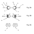
- the magnetic elements 30 are shown as rings in which a first side is positively charged, for example the side 32, while the opposite side 34 is negatively charged. It is not necessary for the magnetic elements 30 to be of such a shape as they could have any suitable shape.
- Figure 2B shows magnetic elements 30' which have a generally rectangular cross-section. The magnetic elements 30 could similarly be tubular, and/or have an oblong, or circular, square cross-section and so on.
- granular metal particles 30" are embedded into the polymer material of the structure in specific points of need in the frame.
- Metal particles 30" could also be included in the entire polymer compound of which the frame is made. The frame can then be magnetized/polarized in the sections where it is needed.
- magnetic elements 30 are hereinafter intended to include reference to the magnetic elements 30' and to the polymer containing the metal particles 30" or to the metal particles 30" themselves as appropriate.
- the magnetic elements 30 may be made of any suitable magnetic materials including: NdFeB (neodymium), FeCrCo, SMCo or PtCo.
- the magnetic elements 30 may be coated with a biocompatible protective coating.
- adjacent surfaces of adjacent strut elements 24 include magnetic elements 30 having the same polarity. This may be achieved, for example, by a strut element being provided on one circumferentially facing side with a north polarity and its opposite circumferentially facing side with a south polarity. Adjacent strut elements 24 will also be provided with polarities in a similar manner, but in the opposite orientation. This results in circumferentially opposing surfaces of adjacent strut elements 24 being provided with the same polarity. As indicated above, this may be achieved in several ways. However, the important aspect is that facing portions of adjacent struts that need to move apart from one another to enable the support structure to expand are provided with magnetism of only the same polarity.
- circumferentially facing magnetic elements 30 each have the same polarity, they will produce a repulsive force between one another, depicted by the arrows 40 in Figures 1 and 2 .
- repulsive force 40 will push adjacent strut elements 24 away from one another, thereby causing the stent frame formed by the undulating wire elements 16 to expand radially and circumferentially outwardly.
- the structure also permits the design of a stent which will generate a continued expansion force against a vessel wall to hold the stent in place against the vessel and to account for changes in vessel shape and/or size over time and during movement of or within the patient.
- a constant expansion force can be generated by suitable selection of the size of the stent 10 as well as by suitable selection of the frame elements 16, in terms of size, shape and the material used therefor.
- the force used by the magnetic elements 30 also enables use of very thin stent struts 24 or strands as well as the use of materials which do not have inherent spring force.
- the stent wire 16 could have a thickness in the region of 0.08 mm for a stent having an expanded diameter of between 1.5 to 2 mm. It is the force generated by the magnetic elements 30 which will provide an opening force to such a stent and not any spring forced generated by such struts or strands 16.
- the stent wires 16 can be made of a polymer material including bioabsorbable and biodegradable materials such as poly-L-lactic acid (PLLA). Other materials include polyurethane, polyethylene, ultrahigh molecular weight polyethylene such as DyneemaTM, polyester, PTFE, silicone and so on.
- the use of thinner elements for the stent structure also reduces the amount of foreign material which is implanted in the body of the patient, and can also lead to faster biodegradation of the structure over time. It is not necessary for the stent or other support structure to be made of a sprung material.
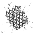
- this shows another embodiment of stent 110 and in particular a section of stent similar to the section shown in Figure 1 .
- the stent 110 has a rhombus or diamond shaped frame structure 116 which may be provided with a polymer coating 130 made of magnetic or paramagnetic material or in another embodiment formed integrally with such material.
- the paramagnetic material is designed to have the same polarisation directions within the diamond shaped areas 136 of the stent structure, so as to generate repulsive forces on the stent frame 116, causing the diamond shape areas to be biased into the expanded configuration shown in Figure 3 .
- wire elements 142-148 of the frame structure 116 can in some embodiments be only partially magnetised, for example at the apices of the diamonds, to produce an arrangement analogous that of the magnetic elements 30 of the embodiment of Figure 1 .
- the coating itself may be bipolar, having the same polarity on its outer surface relative to an inner surface.
- Such an embodiment of core may be part of a structure of the wire elements 16 of the stent 10.
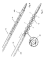
- FIG. 4 this shows a stent 10 mounted on an introducer assembly 70 and covered by a sheath 400.
- the stent 10 is held in a radially contracted configuration on the introducer assembly 70 and in a manner similar to that of conventional sprung stents, for example, stents made of a shape memory material or of a spring material.
- stents made of a shape memory material or of a spring material.
- the person skilled in the art will be familiar with such elements of the introducer assembly 70.
- Figure 5 shows the stent 10 once it has been fed endoluminally into a vessel of a patient on the introducer assembly 70 and located at the site of the vessel to be treated.
- the constraining elements of the introducer assembly 70 for example the sheath 400
- the repulsive magnetic forces will continue to press the stent 10 against the vessel wall once deployed and will therefore assist in holding the stent in position after deployment.
- a medical device of such a structure does not need to rely upon the generation of a mechanical force as with conventional medical devices, but instead makes use of constant magnetic repulsion to keep the support structure of the device in its expanded state against the vessel wall.
- the device can in practice be much more flexible and able to configure to the shape of the vessel or other organ, as well as accommodating changes in the vessel during normal body function and over time.
- the magnetic elements are formed of paramagnetic material
- this can be magnetised after assembly of the stent components, typically by fitting the stent form onto a cylindrical mandril and then magnetising the magnetic elements, typically by an electromagnet or a permanent magnet.
- the stent can be compressed onto an introducer assembly in a manner analogous to stents made of spring material such as spring steel or a shape memory alloy.
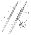
- the stent 10 could be expanded mechanically, for instance by a deployment balloon 600, into the vessel of a patient, in which case the stent 10 will be mounted on a balloon 600 of a balloon catheter 70 as shown in Figure 6 .
- the stent is expanded by conventional balloon expansion as shown in Figure 7 , with the magnetic elements 30 acting simply to maintain a certain opening force to retain the stent 10 in position within the vessel.
- Such a structure could be particularly useful for use in delicate vessels such as the cerebral vessels.
- Magnetic elements could be positioned in any suitable location on the struts to generate repulsive forces biasing these apart from one another.
- the support structure stent for instance, could be a part of an assembly such as a stent graft, occluder, prosthetic valve, filter and so on.
Landscapes
- Health & Medical Sciences (AREA)
- Engineering & Computer Science (AREA)
- Biomedical Technology (AREA)
- Life Sciences & Earth Sciences (AREA)
- General Health & Medical Sciences (AREA)
- Veterinary Medicine (AREA)
- Public Health (AREA)
- Heart & Thoracic Surgery (AREA)
- Vascular Medicine (AREA)
- Animal Behavior & Ethology (AREA)
- Transplantation (AREA)
- Oral & Maxillofacial Surgery (AREA)
- Cardiology (AREA)
- Surgery (AREA)
- Physics & Mathematics (AREA)
- Optics & Photonics (AREA)
- Reproductive Health (AREA)
- Nuclear Medicine, Radiotherapy & Molecular Imaging (AREA)
- Medical Informatics (AREA)
- Molecular Biology (AREA)
- Prostheses (AREA)
Applications Claiming Priority (1)
| Application Number | Priority Date | Filing Date | Title |
|---|---|---|---|
| GB1408479.2A GB2526265B (en) | 2014-05-13 | 2014-05-13 | Medical device having magnetically expandable frame |
Publications (2)
| Publication Number | Publication Date |
|---|---|
| EP2944293A1 true EP2944293A1 (de) | 2015-11-18 |
| EP2944293B1 EP2944293B1 (de) | 2017-04-26 |
Family
ID=51032698
Family Applications (1)
| Application Number | Title | Priority Date | Filing Date |
|---|---|---|---|
| EP15275132.7A Active EP2944293B1 (de) | 2014-05-13 | 2015-05-11 | Medizinische vorrichtung mit magnetisch expandierbarem rahmen |
Country Status (3)
| Country | Link |
|---|---|
| US (1) | US9526639B2 (de) |
| EP (1) | EP2944293B1 (de) |
| GB (1) | GB2526265B (de) |
Families Citing this family (7)
| Publication number | Priority date | Publication date | Assignee | Title |
|---|---|---|---|---|
| CN108403268B (zh) * | 2018-03-22 | 2024-02-20 | 镇江市第三人民医院 | 一种带磁性的可收缩气管支架 |
| JP7017105B2 (ja) * | 2018-03-23 | 2022-02-08 | 日本ゼオン株式会社 | ステント |
| US11998467B2 (en) * | 2019-01-28 | 2024-06-04 | Tensor Flow Ventures Llc | Stent delivery for vascular surgery |
| US11666464B2 (en) | 2019-01-28 | 2023-06-06 | Tensor Flow Ventures Llc | Magnetic stent and stent delivery |
| WO2021178312A1 (en) | 2020-03-02 | 2021-09-10 | Gyrus Acmi, Inc. D/B/A Olympus Surgical Technologies America | Magnetically deployable urinary stent |
| US20230277348A1 (en) | 2021-07-26 | 2023-09-07 | Tensor Flow Ventures Llc | Dual stent and delivery system, delivery tool apparatus, and method of delivery of dual stents |
| US20230026939A1 (en) | 2021-07-26 | 2023-01-26 | Tensor Flow Ventures Llc | Dual stent and delivery system, delivery tool apparatus, and method of delivery of dual stents |
Citations (1)
| Publication number | Priority date | Publication date | Assignee | Title |
|---|---|---|---|---|
| US20090287293A1 (en) * | 2008-05-15 | 2009-11-19 | Mailhot Jr Robert | Magnetically induced radial expansion vascular stent |
Family Cites Families (6)
| Publication number | Priority date | Publication date | Assignee | Title |
|---|---|---|---|---|
| BE1006440A3 (fr) * | 1992-12-21 | 1994-08-30 | Dereume Jean Pierre Georges Em | Endoprothese luminale et son procede de preparation. |
| US6673104B2 (en) * | 2001-03-15 | 2004-01-06 | Scimed Life Systems, Inc. | Magnetic stent |
| US7713298B2 (en) | 2004-06-29 | 2010-05-11 | Micardia Corporation | Methods for treating cardiac valves with adjustable implants |
| US20060212113A1 (en) | 2005-02-24 | 2006-09-21 | Shaolian Samuel M | Externally adjustable endovascular graft implant |
| US20070142907A1 (en) | 2005-12-16 | 2007-06-21 | Micardia Corporation | Adjustable prosthetic valve implant |
| US20110257724A1 (en) | 2010-04-15 | 2011-10-20 | Medtronic Vascular, Inc. | Flexible Stent Device with Magnetic Connections |
-
2014
- 2014-05-13 GB GB1408479.2A patent/GB2526265B/en active Active
-
2015
- 2015-05-11 US US14/709,067 patent/US9526639B2/en active Active
- 2015-05-11 EP EP15275132.7A patent/EP2944293B1/de active Active
Patent Citations (1)
| Publication number | Priority date | Publication date | Assignee | Title |
|---|---|---|---|---|
| US20090287293A1 (en) * | 2008-05-15 | 2009-11-19 | Mailhot Jr Robert | Magnetically induced radial expansion vascular stent |
Also Published As
| Publication number | Publication date |
|---|---|
| US20150328022A1 (en) | 2015-11-19 |
| GB2526265B (en) | 2016-08-17 |
| GB201408479D0 (en) | 2014-06-25 |
| GB2526265A (en) | 2015-11-25 |
| US9526639B2 (en) | 2016-12-27 |
| EP2944293B1 (de) | 2017-04-26 |
Similar Documents
| Publication | Publication Date | Title |
|---|---|---|
| EP2944293B1 (de) | Medizinische vorrichtung mit magnetisch expandierbarem rahmen | |
| US9788841B2 (en) | Implantable medical device with lumen constriction | |
| US9370437B2 (en) | Stent having less invasive ends | |
| US5868780A (en) | Stents for supporting lumens in living tissue | |
| US6497722B1 (en) | Methods and apparatus for in-vivo tailored stents indicated for use in tortuous anatomy | |
| ES2731371T3 (es) | Endoprótesis que contiene acero ferroso multifase | |
| CN109069270B (zh) | 可扩张支架及压握和扩张此类支架的方法 | |
| JP4651943B2 (ja) | 腸管内に埋設可能なプロテーゼ | |
| US10463519B2 (en) | Delivery system for implantable medical device | |
| CN107072775B (zh) | 用于可球囊扩张的内假体的递送装置 | |
| CN106659576B (zh) | 带有改善的收回效果的内置假体递送系统 | |
| JPH0724688B2 (ja) | 血管内で放射状に膨脹可能なステント及びその移植装置 | |
| JP2022019920A (ja) | 非外傷性スペーサを備えたステント | |
| EP3025684B1 (de) | Selbstexpandierbarer stent | |
| EP2932940B1 (de) | Magnetisch expandierbare medizinische vorrichtung | |
| WO2013119736A2 (en) | Bioabsorbable stent and implantable medical device | |
| EP3981367A1 (de) | Stent mit ablenkendem verbinder | |
| US8870943B2 (en) | Stent structure for implantable medical device | |
| EP3156003A1 (de) | Filter zur verwendung in einem körpergefäss | |
| EP2708210B1 (de) | Stentstruktur für implantierbare medizinische vorrichtung | |
| GB2506346A (en) | Stent structure for implantable medical device |
Legal Events
| Date | Code | Title | Description |
|---|---|---|---|
| PUAI | Public reference made under article 153(3) epc to a published international application that has entered the european phase |
Free format text: ORIGINAL CODE: 0009012 |
|
| AK | Designated contracting states |
Kind code of ref document: A1 Designated state(s): AL AT BE BG CH CY CZ DE DK EE ES FI FR GB GR HR HU IE IS IT LI LT LU LV MC MK MT NL NO PL PT RO RS SE SI SK SM TR |
|
| AX | Request for extension of the european patent |
Extension state: BA ME |
|
| 17P | Request for examination filed |
Effective date: 20160122 |
|
| RBV | Designated contracting states (corrected) |
Designated state(s): AL AT BE BG CH CY CZ DE DK EE ES FI FR GB GR HR HU IE IS IT LI LT LU LV MC MK MT NL NO PL PT RO RS SE SI SK SM TR |
|
| 17Q | First examination report despatched |
Effective date: 20160908 |
|
| GRAP | Despatch of communication of intention to grant a patent |
Free format text: ORIGINAL CODE: EPIDOSNIGR1 |
|
| STAA | Information on the status of an ep patent application or granted ep patent |
Free format text: STATUS: GRANT OF PATENT IS INTENDED |
|
| INTG | Intention to grant announced |
Effective date: 20161123 |
|
| GRAS | Grant fee paid |
Free format text: ORIGINAL CODE: EPIDOSNIGR3 |
|
| GRAA | (expected) grant |
Free format text: ORIGINAL CODE: 0009210 |
|
| STAA | Information on the status of an ep patent application or granted ep patent |
Free format text: STATUS: THE PATENT HAS BEEN GRANTED |
|
| RBV | Designated contracting states (corrected) |
Designated state(s): AL AT BE BG CH CY CZ DE DK EE ES FI FR GR HR HU IE IS IT LI LT LU LV MC MK MT NL NO PL PT RO RS SE SI SK SM TR |
|
| AK | Designated contracting states |
Kind code of ref document: B1 Designated state(s): AL AT BE BG CH CY CZ DE DK EE ES FI FR GR HR HU IE IS IT LI LT LU LV MC MK MT NL NO PL PT RO RS SE SI SK SM TR |
|
| REG | Reference to a national code |
Ref country code: CH Ref legal event code: EP |
|
| REG | Reference to a national code |
Ref country code: AT Ref legal event code: REF Ref document number: 887226 Country of ref document: AT Kind code of ref document: T Effective date: 20170515 |
|
| REG | Reference to a national code |
Ref country code: IE Ref legal event code: FG4D |
|
| REG | Reference to a national code |
Ref country code: DE Ref legal event code: R096 Ref document number: 602015002445 Country of ref document: DE |
|
| REG | Reference to a national code |
Ref country code: NL Ref legal event code: MP Effective date: 20170426 |
|
| REG | Reference to a national code |
Ref country code: LT Ref legal event code: MG4D |
|
| REG | Reference to a national code |
Ref country code: AT Ref legal event code: MK05 Ref document number: 887226 Country of ref document: AT Kind code of ref document: T Effective date: 20170426 |
|
| PG25 | Lapsed in a contracting state [announced via postgrant information from national office to epo] |
Ref country code: NL Free format text: LAPSE BECAUSE OF FAILURE TO SUBMIT A TRANSLATION OF THE DESCRIPTION OR TO PAY THE FEE WITHIN THE PRESCRIBED TIME-LIMIT Effective date: 20170426 |
|
| PG25 | Lapsed in a contracting state [announced via postgrant information from national office to epo] |
Ref country code: LT Free format text: LAPSE BECAUSE OF FAILURE TO SUBMIT A TRANSLATION OF THE DESCRIPTION OR TO PAY THE FEE WITHIN THE PRESCRIBED TIME-LIMIT Effective date: 20170426 Ref country code: ES Free format text: LAPSE BECAUSE OF FAILURE TO SUBMIT A TRANSLATION OF THE DESCRIPTION OR TO PAY THE FEE WITHIN THE PRESCRIBED TIME-LIMIT Effective date: 20170426 Ref country code: GR Free format text: LAPSE BECAUSE OF FAILURE TO SUBMIT A TRANSLATION OF THE DESCRIPTION OR TO PAY THE FEE WITHIN THE PRESCRIBED TIME-LIMIT Effective date: 20170727 Ref country code: FI Free format text: LAPSE BECAUSE OF FAILURE TO SUBMIT A TRANSLATION OF THE DESCRIPTION OR TO PAY THE FEE WITHIN THE PRESCRIBED TIME-LIMIT Effective date: 20170426 Ref country code: AT Free format text: LAPSE BECAUSE OF FAILURE TO SUBMIT A TRANSLATION OF THE DESCRIPTION OR TO PAY THE FEE WITHIN THE PRESCRIBED TIME-LIMIT Effective date: 20170426 Ref country code: NO Free format text: LAPSE BECAUSE OF FAILURE TO SUBMIT A TRANSLATION OF THE DESCRIPTION OR TO PAY THE FEE WITHIN THE PRESCRIBED TIME-LIMIT Effective date: 20170726 Ref country code: HR Free format text: LAPSE BECAUSE OF FAILURE TO SUBMIT A TRANSLATION OF THE DESCRIPTION OR TO PAY THE FEE WITHIN THE PRESCRIBED TIME-LIMIT Effective date: 20170426 |
|
| PG25 | Lapsed in a contracting state [announced via postgrant information from national office to epo] |
Ref country code: SE Free format text: LAPSE BECAUSE OF FAILURE TO SUBMIT A TRANSLATION OF THE DESCRIPTION OR TO PAY THE FEE WITHIN THE PRESCRIBED TIME-LIMIT Effective date: 20170426 Ref country code: PL Free format text: LAPSE BECAUSE OF FAILURE TO SUBMIT A TRANSLATION OF THE DESCRIPTION OR TO PAY THE FEE WITHIN THE PRESCRIBED TIME-LIMIT Effective date: 20170426 Ref country code: RS Free format text: LAPSE BECAUSE OF FAILURE TO SUBMIT A TRANSLATION OF THE DESCRIPTION OR TO PAY THE FEE WITHIN THE PRESCRIBED TIME-LIMIT Effective date: 20170426 Ref country code: LV Free format text: LAPSE BECAUSE OF FAILURE TO SUBMIT A TRANSLATION OF THE DESCRIPTION OR TO PAY THE FEE WITHIN THE PRESCRIBED TIME-LIMIT Effective date: 20170426 Ref country code: IS Free format text: LAPSE BECAUSE OF FAILURE TO SUBMIT A TRANSLATION OF THE DESCRIPTION OR TO PAY THE FEE WITHIN THE PRESCRIBED TIME-LIMIT Effective date: 20170826 Ref country code: BG Free format text: LAPSE BECAUSE OF FAILURE TO SUBMIT A TRANSLATION OF THE DESCRIPTION OR TO PAY THE FEE WITHIN THE PRESCRIBED TIME-LIMIT Effective date: 20170726 |
|
| REG | Reference to a national code |
Ref country code: DE Ref legal event code: R097 Ref document number: 602015002445 Country of ref document: DE |
|
| PG25 | Lapsed in a contracting state [announced via postgrant information from national office to epo] |
Ref country code: MC Free format text: LAPSE BECAUSE OF FAILURE TO SUBMIT A TRANSLATION OF THE DESCRIPTION OR TO PAY THE FEE WITHIN THE PRESCRIBED TIME-LIMIT Effective date: 20170426 Ref country code: DK Free format text: LAPSE BECAUSE OF FAILURE TO SUBMIT A TRANSLATION OF THE DESCRIPTION OR TO PAY THE FEE WITHIN THE PRESCRIBED TIME-LIMIT Effective date: 20170426 Ref country code: CZ Free format text: LAPSE BECAUSE OF FAILURE TO SUBMIT A TRANSLATION OF THE DESCRIPTION OR TO PAY THE FEE WITHIN THE PRESCRIBED TIME-LIMIT Effective date: 20170426 Ref country code: EE Free format text: LAPSE BECAUSE OF FAILURE TO SUBMIT A TRANSLATION OF THE DESCRIPTION OR TO PAY THE FEE WITHIN THE PRESCRIBED TIME-LIMIT Effective date: 20170426 Ref country code: RO Free format text: LAPSE BECAUSE OF FAILURE TO SUBMIT A TRANSLATION OF THE DESCRIPTION OR TO PAY THE FEE WITHIN THE PRESCRIBED TIME-LIMIT Effective date: 20170426 Ref country code: SK Free format text: LAPSE BECAUSE OF FAILURE TO SUBMIT A TRANSLATION OF THE DESCRIPTION OR TO PAY THE FEE WITHIN THE PRESCRIBED TIME-LIMIT Effective date: 20170426 |
|
| PG25 | Lapsed in a contracting state [announced via postgrant information from national office to epo] |
Ref country code: IT Free format text: LAPSE BECAUSE OF FAILURE TO SUBMIT A TRANSLATION OF THE DESCRIPTION OR TO PAY THE FEE WITHIN THE PRESCRIBED TIME-LIMIT Effective date: 20170426 Ref country code: SM Free format text: LAPSE BECAUSE OF FAILURE TO SUBMIT A TRANSLATION OF THE DESCRIPTION OR TO PAY THE FEE WITHIN THE PRESCRIBED TIME-LIMIT Effective date: 20170426 |
|
| PLBE | No opposition filed within time limit |
Free format text: ORIGINAL CODE: 0009261 |
|
| STAA | Information on the status of an ep patent application or granted ep patent |
Free format text: STATUS: NO OPPOSITION FILED WITHIN TIME LIMIT |
|
| PG25 | Lapsed in a contracting state [announced via postgrant information from national office to epo] |
Ref country code: LU Free format text: LAPSE BECAUSE OF NON-PAYMENT OF DUE FEES Effective date: 20170511 |
|
| 26N | No opposition filed |
Effective date: 20180129 |
|
| REG | Reference to a national code |
Ref country code: BE Ref legal event code: MM Effective date: 20170531 |
|
| REG | Reference to a national code |
Ref country code: FR Ref legal event code: ST Effective date: 20180330 |
|
| PG25 | Lapsed in a contracting state [announced via postgrant information from national office to epo] |
Ref country code: SI Free format text: LAPSE BECAUSE OF FAILURE TO SUBMIT A TRANSLATION OF THE DESCRIPTION OR TO PAY THE FEE WITHIN THE PRESCRIBED TIME-LIMIT Effective date: 20170426 |
|
| PG25 | Lapsed in a contracting state [announced via postgrant information from national office to epo] |
Ref country code: BE Free format text: LAPSE BECAUSE OF NON-PAYMENT OF DUE FEES Effective date: 20170531 Ref country code: FR Free format text: LAPSE BECAUSE OF NON-PAYMENT OF DUE FEES Effective date: 20170626 |
|
| PG25 | Lapsed in a contracting state [announced via postgrant information from national office to epo] |
Ref country code: MT Free format text: LAPSE BECAUSE OF NON-PAYMENT OF DUE FEES Effective date: 20170511 |
|
| REG | Reference to a national code |
Ref country code: CH Ref legal event code: PL |
|
| PG25 | Lapsed in a contracting state [announced via postgrant information from national office to epo] |
Ref country code: LI Free format text: LAPSE BECAUSE OF NON-PAYMENT OF DUE FEES Effective date: 20180531 Ref country code: CH Free format text: LAPSE BECAUSE OF NON-PAYMENT OF DUE FEES Effective date: 20180531 |
|
| PG25 | Lapsed in a contracting state [announced via postgrant information from national office to epo] |
Ref country code: HU Free format text: LAPSE BECAUSE OF FAILURE TO SUBMIT A TRANSLATION OF THE DESCRIPTION OR TO PAY THE FEE WITHIN THE PRESCRIBED TIME-LIMIT; INVALID AB INITIO Effective date: 20150511 |
|
| PG25 | Lapsed in a contracting state [announced via postgrant information from national office to epo] |
Ref country code: CY Free format text: LAPSE BECAUSE OF FAILURE TO SUBMIT A TRANSLATION OF THE DESCRIPTION OR TO PAY THE FEE WITHIN THE PRESCRIBED TIME-LIMIT Effective date: 20170426 |
|
| PG25 | Lapsed in a contracting state [announced via postgrant information from national office to epo] |
Ref country code: MK Free format text: LAPSE BECAUSE OF FAILURE TO SUBMIT A TRANSLATION OF THE DESCRIPTION OR TO PAY THE FEE WITHIN THE PRESCRIBED TIME-LIMIT Effective date: 20170426 |
|
| PG25 | Lapsed in a contracting state [announced via postgrant information from national office to epo] |
Ref country code: TR Free format text: LAPSE BECAUSE OF FAILURE TO SUBMIT A TRANSLATION OF THE DESCRIPTION OR TO PAY THE FEE WITHIN THE PRESCRIBED TIME-LIMIT Effective date: 20170426 |
|
| PG25 | Lapsed in a contracting state [announced via postgrant information from national office to epo] |
Ref country code: PT Free format text: LAPSE BECAUSE OF FAILURE TO SUBMIT A TRANSLATION OF THE DESCRIPTION OR TO PAY THE FEE WITHIN THE PRESCRIBED TIME-LIMIT Effective date: 20170426 |
|
| PG25 | Lapsed in a contracting state [announced via postgrant information from national office to epo] |
Ref country code: AL Free format text: LAPSE BECAUSE OF FAILURE TO SUBMIT A TRANSLATION OF THE DESCRIPTION OR TO PAY THE FEE WITHIN THE PRESCRIBED TIME-LIMIT Effective date: 20170426 |
|
| P01 | Opt-out of the competence of the unified patent court (upc) registered |
Effective date: 20230602 |
|
| PGFP | Annual fee paid to national office [announced via postgrant information from national office to epo] |
Ref country code: DE Payment date: 20250528 Year of fee payment: 11 |
|
| PGFP | Annual fee paid to national office [announced via postgrant information from national office to epo] |
Ref country code: IE Payment date: 20250520 Year of fee payment: 11 |