EP2944160B1 - Lighting control analyzer - Google Patents
Lighting control analyzer Download PDFInfo
- Publication number
- EP2944160B1 EP2944160B1 EP14700794.2A EP14700794A EP2944160B1 EP 2944160 B1 EP2944160 B1 EP 2944160B1 EP 14700794 A EP14700794 A EP 14700794A EP 2944160 B1 EP2944160 B1 EP 2944160B1
- Authority
- EP
- European Patent Office
- Prior art keywords
- area
- lighting
- lighting control
- light settings
- lighting device
- Prior art date
- Legal status (The legal status is an assumption and is not a legal conclusion. Google has not performed a legal analysis and makes no representation as to the accuracy of the status listed.)
- Active
Links
- 238000005286 illumination Methods 0.000 claims description 78
- 230000006399 behavior Effects 0.000 claims description 55
- 238000011217 control strategy Methods 0.000 claims description 43
- 238000000034 method Methods 0.000 claims description 25
- 238000010438 heat treatment Methods 0.000 claims description 9
- 238000004378 air conditioning Methods 0.000 claims description 7
- 238000009423 ventilation Methods 0.000 claims description 7
- 238000001514 detection method Methods 0.000 claims description 5
- 238000013507 mapping Methods 0.000 claims description 4
- 230000004044 response Effects 0.000 claims description 3
- 230000001276 controlling effect Effects 0.000 description 8
- 239000013598 vector Substances 0.000 description 5
- 238000009877 rendering Methods 0.000 description 4
- 238000001816 cooling Methods 0.000 description 2
- 238000012544 monitoring process Methods 0.000 description 2
- 230000002159 abnormal effect Effects 0.000 description 1
- 238000013500 data storage Methods 0.000 description 1
- 230000001419 dependent effect Effects 0.000 description 1
- 230000000694 effects Effects 0.000 description 1
- 230000004313 glare Effects 0.000 description 1
- 230000007774 longterm Effects 0.000 description 1
- 230000003287 optical effect Effects 0.000 description 1
- 238000005457 optimization Methods 0.000 description 1
- 230000001105 regulatory effect Effects 0.000 description 1
- 230000003595 spectral effect Effects 0.000 description 1
Images
Classifications
-
- H—ELECTRICITY
- H05—ELECTRIC TECHNIQUES NOT OTHERWISE PROVIDED FOR
- H05B—ELECTRIC HEATING; ELECTRIC LIGHT SOURCES NOT OTHERWISE PROVIDED FOR; CIRCUIT ARRANGEMENTS FOR ELECTRIC LIGHT SOURCES, IN GENERAL
- H05B47/00—Circuit arrangements for operating light sources in general, i.e. where the type of light source is not relevant
- H05B47/10—Controlling the light source
- H05B47/175—Controlling the light source by remote control
-
- F—MECHANICAL ENGINEERING; LIGHTING; HEATING; WEAPONS; BLASTING
- F24—HEATING; RANGES; VENTILATING
- F24F—AIR-CONDITIONING; AIR-HUMIDIFICATION; VENTILATION; USE OF AIR CURRENTS FOR SCREENING
- F24F11/00—Control or safety arrangements
- F24F11/30—Control or safety arrangements for purposes related to the operation of the system, e.g. for safety or monitoring
- F24F11/46—Improving electric energy efficiency or saving
-
- F—MECHANICAL ENGINEERING; LIGHTING; HEATING; WEAPONS; BLASTING
- F24—HEATING; RANGES; VENTILATING
- F24F—AIR-CONDITIONING; AIR-HUMIDIFICATION; VENTILATION; USE OF AIR CURRENTS FOR SCREENING
- F24F11/00—Control or safety arrangements
- F24F11/62—Control or safety arrangements characterised by the type of control or by internal processing, e.g. using fuzzy logic, adaptive control or estimation of values
-
- G—PHYSICS
- G05—CONTROLLING; REGULATING
- G05B—CONTROL OR REGULATING SYSTEMS IN GENERAL; FUNCTIONAL ELEMENTS OF SUCH SYSTEMS; MONITORING OR TESTING ARRANGEMENTS FOR SUCH SYSTEMS OR ELEMENTS
- G05B15/00—Systems controlled by a computer
- G05B15/02—Systems controlled by a computer electric
-
- H—ELECTRICITY
- H05—ELECTRIC TECHNIQUES NOT OTHERWISE PROVIDED FOR
- H05B—ELECTRIC HEATING; ELECTRIC LIGHT SOURCES NOT OTHERWISE PROVIDED FOR; CIRCUIT ARRANGEMENTS FOR ELECTRIC LIGHT SOURCES, IN GENERAL
- H05B47/00—Circuit arrangements for operating light sources in general, i.e. where the type of light source is not relevant
- H05B47/10—Controlling the light source
- H05B47/105—Controlling the light source in response to determined parameters
- H05B47/115—Controlling the light source in response to determined parameters by determining the presence or movement of objects or living beings
-
- H—ELECTRICITY
- H05—ELECTRIC TECHNIQUES NOT OTHERWISE PROVIDED FOR
- H05B—ELECTRIC HEATING; ELECTRIC LIGHT SOURCES NOT OTHERWISE PROVIDED FOR; CIRCUIT ARRANGEMENTS FOR ELECTRIC LIGHT SOURCES, IN GENERAL
- H05B47/00—Circuit arrangements for operating light sources in general, i.e. where the type of light source is not relevant
- H05B47/10—Controlling the light source
- H05B47/16—Controlling the light source by timing means
-
- Y—GENERAL TAGGING OF NEW TECHNOLOGICAL DEVELOPMENTS; GENERAL TAGGING OF CROSS-SECTIONAL TECHNOLOGIES SPANNING OVER SEVERAL SECTIONS OF THE IPC; TECHNICAL SUBJECTS COVERED BY FORMER USPC CROSS-REFERENCE ART COLLECTIONS [XRACs] AND DIGESTS
- Y02—TECHNOLOGIES OR APPLICATIONS FOR MITIGATION OR ADAPTATION AGAINST CLIMATE CHANGE
- Y02B—CLIMATE CHANGE MITIGATION TECHNOLOGIES RELATED TO BUILDINGS, e.g. HOUSING, HOUSE APPLIANCES OR RELATED END-USER APPLICATIONS
- Y02B20/00—Energy efficient lighting technologies, e.g. halogen lamps or gas discharge lamps
- Y02B20/40—Control techniques providing energy savings, e.g. smart controller or presence detection
Definitions
- the present invention relates to lighting systems, and in particular to methods and apparatus related to control of such systems.
- Illumination of a room is typically provided by a lighting system comprising a plurality of lighting devices.
- Lighting systems often comprise controllers for controlling the lighting devices in order to provide a desired illumination in an energy efficient manner.
- some lighting systems are equipped with sensors, such as motion or presence detectors. In such lighting systems, information from the sensors may for example be used to determine which lighting devices may be switched off or dimmed, without affecting the illumination of occupied parts of the room, in order to save energy.
- US 2012 0066168 A1 discloses an analyser for determining an occupancy behavior based inter alia on light settings.
- An object of at least some of the embodiments of the present invention is to provide a lighting control analyzer, and a corresponding method, for determining occupancy behavior in an area arranged to be illuminated by at least one lighting device, thereby allowing for, e.g., a more energy efficient illumination of the area, and/or a more efficient use of at least one system associated with the area, such as a system for heating, ventilation, air conditioning and/or blind control.
- a lighting control analyzer for determining occupancy behavior in an area arranged to be at least partly illuminated by at least one lighting device controllable by a lighting controller.
- the lighting control analyzer is adapted to receive light settings for control of the at least one lighting device, wherein the light settings are determined by the lighting controller, using a lighting control strategy for the area.
- the lighting control strategy represents a desired illumination of at least part of the area, based on presence information associated with at least one location in the area.
- the lighting control analyzer is further adapted to determine the occupancy behavior, based on the light settings for a plurality of time instants and the lighting control strategy, wherein said light settings correspond to dimming levels from at least one dimmer associated with said at least one lighting device, and wherein occupancy behavior comprises normal/common locations of occupants in the area, how often different locations in the area are occupied and/or locations at which occupants normally enter/exit the area.
- a method of determining occupancy behavior in an area arranged to be at least partly illuminated by at least one lighting device comprises receiving light settings for control of the at least one lighting device, wherein the light settings are determined using a lighting control strategy for the area.
- the lighting control strategy represents a desired illumination of at least part of the area, based on presence information associated with at least one location in the area.
- the method further comprises determining the occupancy behavior, based on the light settings for a plurality of time instants and the lighting control strategy, wherein said light settings correspond to dimming levels from at least one dimmer associated with said at least one lighting device, and wherein occupancy behavior comprises normal/common locations of occupants in the area, how often different locations in the area are occupied and/or locations at which occupants normally enter/exit the area.
- the inventors have realized that when information about an area (e.g. presence of occupants or external light) is used to obtain light settings for illumination of the area using a lighting control strategy for the area, at least some of this information may be retrievable from the light settings, based on knowledge about the lighting control strategy. Accordingly, light settings for control of at least one lighting device adapted to illuminate at least part of the area, maybe used together with the lighting control strategy to determine occupancy behavior in the area.
- information about an area e.g. presence of occupants or external light
- the present invention is advantageous in that occupancy behavior may be determined based on light settings for control of the at least one lighting device and the lighting control strategy, i.e. without additional input from sensors or other additional components. Moreover, since the lighting controller controls the at least one lighting device using the light settings, the light settings may be available at the lighting controller, i.e. the lighting control analyzer need not gather information from the at least one lighting device. The light settings may be received from the at least one lighting device, from the lighting controller, or via any other units of the lighting system.
- the lighting control analyzer may be added to an existing lighting system (comprising a lighting controller controlling at least one lighting device) by connecting it to the lighting controller, and the occupancy behavior determined by the lighting control analyzer may be used by the lighting controller to adapt the illumination provided in the area by the at least one lighting device, which may for example allow for a more energy efficient illumination of the area.
- Another advantage of the present invention is that the determined occupancy behavior may be used to adapt and/or improve settings of other systems, such as systems associated with illumination, heating, ventilation and/or air conditioning of the area. This may for example allow for a more energy efficient utilization of these systems.
- the lighting control strategy represents a desired illumination of at least part of the area, based on presence information (e.g. presence of at least one occupant in at least one location of the area), the light settings determined by the lighting controller carry information about presence (or absence) of occupants in the area, since the light settings are determined based on such information.
- the lighting control analyzer may estimate presence of occupants based on the received light settings.
- the lighting control analyzer may consider received light settings for intensely illuminating a location as indicating the presence of an occupant close to that location.
- the lighting control analyzer may take advantage of already existing presence sensors used by the lighting controller to determine a suitable illumination.
- the lighting controller may for example receive presence information from at least one presence sensor adapted to detect presence of at least one occupant in at least one location of the area.
- the lighting control strategy may comprise an algorithm which determines the light settings, based on the presence information.
- the occupancy behavior determined by the lighting control analyzer may for example comprise normal/common locations of occupants in the area, how often different locations in the area are occupied and/or locations at which occupants normally enter/exit the area. Such occupancy behavior may for example be determined based on the above described estimated presence of occupants.
- the area may be, e.g., a room, a set of rooms, a floor of a building, a section of a floor (or of a room), or an outside space with illumination.
- the area may even be a space comprising several floors.
- the at least one lighting device may be a plurality of lighting devices (at least some of which being) adapted to illuminate different parts of the area. Additionally, or alternatively, one or more of the at least one lighting device may be movable/rotatable (or may be equipped with optical elements such as mirrors or lenses arranged to direct the light output of the lighting device to different parts of the area), such that a single lighting device may illuminate different parts of the area, depending on the light settings.
- the lighting controller may be a device comprising e.g. a processor or any other type of processing unit/means.
- the lighting controller may be a functional aspect of another unit/device such as a controller or control system for a floor or building, e.g., involving heating, ventilation, air conditioning etc.
- the lighting controller may be adapted to receive information about illumination of at least one location in the area provided by light sources other than the at least one lighting device.
- the at least one light sensor may measure the external light itself or a combined illumination comprising the external light and an illumination provided by the at least one lighting device, from which the contribution provided by the external light may be estimated.
- the lighting controller may be adapted to determine the light settings, and thereby control the at least one lighting device, additionally based on the received illumination information (i.e. based on the received light settings, the received illumination information, and the lighting control strategy).
- the lighting controller may control the at least one lighting device to provide less illumination than in the case that the area is not already illuminated by external light.
- Light settings determined in this way may be indicative of light contributions from light sources other than the at least one lighting device.
- the light settings may comprise instructions for selecting and/or switching on/off one or more of the at least one lighting device.
- the light settings may comprise instructions for selecting, e.g., amplitude, orientation (i.e. direction of illumination), frequency, or other spectral properties of the at least one lighting device.
- at least one dimmer may be associated with the at least one lighting device and the light settings may comprise (or may be) dimming levels for the at least one dimmer.
- the at least one dimmer may be adapted to control the light output of at least one of the at least one lighting device.
- the lighting control strategy may comprise constructive instructions for determination of the light settings, e.g. by the lighting controller. It may for example comprise algorithms on how to calculate the light settings.
- the lighting control strategy available at the lighting control analyzer may be a general guideline on how the area is to be illuminated, i.e. it need not comprise detailed information on how to calculate the light settings. In particular, this means that when determining the occupancy behavior based on the light settings and the lighting control strategy, the lighting control analyzer may not have knowledge of algorithms for determining light settings. Indeed, the lighting control analyzer may instead have access to general guidelines on how the lighting controller controls the illumination, and may comprise a processor (or any other type of processing means) for determining the occupancy behavior, based on such guidelines and the received light settings.
- the lighting control strategy may represent (or describe) a desired illumination to be provided in at least part of the area, based on presence of at least one occupant in at least one location of the area, i.e. the lighting control strategy may represent different desired illuminations of the area associated with presence of occupants in different locations of the area.
- the lighting control strategy may suggest illuminating locations close to occupants more (intensely) than locations far from occupants.
- the lighting control analyzer may for example comprise a processor (or any other type of processing means) for determining the occupancy behavior, based on the received light settings and the lighting control strategy.
- the lighting control analyzer may be adapted to determine the occupancy behavior, based on light settings for a plurality of time instants (or time intervals/periods), i.e. the lighting control analyzer may be adapted to receive light settings associated with a plurality of time instants (or time intervals/periods) and to determine the occupancy behavior, based on (at least some of) these received light settings.
- the present embodiment improves the accuracy of the determined occupancy behavior since effects of temporary distortions and/or short term deviations from normal/standard occupancy behavior are reduced.
- the occupancy behavior may be determined based on as many received light settings as possible in order to increase accuracy.
- it may be desirable to provide updated information about occupancy behavior so that the occupancy behavior may in some examples be determined based on a sequence of recent time instants (e.g. the last couple of minutes, hours, days, months, or years).
- the lighting control analyzer may comprise a memory (or look-up table or any other means of data storage) adapted to store at least some of the received light settings, and the lighting control analyzer may be adapted to determine the occupancy behavior, based on at least some of the stored light settings.
- the lighting control analyzer may be adapted to determine a level of illumination (or light distribution) of at least part of the area provided by the at least one lighting device, based on the received light settings.
- the lighting control analyzer may have access to a mapping (or correlation) between light settings for the at least one lighting device and corresponding illuminations of the area.
- the lighting control analyzer may be adapted to determine the occupancy behavior, based on the determined illumination level and the lighting control strategy.
- the lighting control analyzer may be adapted to determine momentary occupancy levels of locations in the area, based on the determined illumination and the lighting control strategy, wherein a momentary occupancy level of a location is indicative of the probability that the location is occupied at a certain time.
- the momentary occupancy levels may be determined based on received light settings for a single time instant, i.e. they need not be based on a sequence of received light settings.
- the lighting control analyzer may be adapted to determine occupancy levels of locations in the area based on time averages of the determined momentary occupancy levels, wherein the occupancy level of a location is indicative of how often the location is occupied (e.g. the occupancy level may be indicative of a percentage of a time interval that the location is normally occupied). Hence, the occupancy levels reflect time-average properties of the area, rather than the temporary properties indicated by the momentary occupancy levels. Additionally or alternatively, the lighting control analyzer may be adapted to determine at least one occupant position in the area based on time averages of the determined momentary occupancy levels, wherein the occupant positions estimate normal/common locations of occupants in the area (i.e. a location which is more often occupied than other locations in the area).
- Occupancy behavior such as occupancy levels and/or occupant positions may be, e.g., useful for optimizing space use of the area and/or for configuration of systems for lighting, heating, ventilation and/or air conditioning of the area.
- the lighting control analyzer may be further adapted to determine: when the received light settings change from a first state corresponding to a power saving mode for the at least one lighting device to a second state corresponding to an active mode of the at least one lighting device, at least one entrance point as a location in the area at which the at least one lighting device is activated (i.e. is switched from a power saving mode to an active mode) to provide illumination.
- the power saving mode refers to a mode in which the at least one lighting device provides less illumination than in an active mode, or in which it does not provide any illumination at all (e.g. is switched off or inactivated).
- the information that the at least one lighting device is in a power saving mode may indicate that the area is unoccupied.
- the information that one or more lighting devices switch to an active mode may indicate that someone has entered the area at a location illuminated by the one or more lighting devices. Hence, such a location may be identified as an entrance point of the area. Similarly, an exit point of the area (which may of course coincide with an entrance point) may be detected as a location illuminated just before the at least one lighting device enters a power saving mode. Knowledge of entrance/exits points of the area may be useful for detecting abnormal or unexpected behavior. For example, if sudden presence of a person is detected in a region too far from an entrance point, this may be an indication that the person has entered the room from an unexpected location, and an alarm may be issued.
- the lighting control analyzer may be adapted to detect when the received light settings correspond to a power saving mode of the at least one lighting device (or when the at least one lighting device has been in a power saving mode during a time longer than a threshold, e.g. to ensure that the room is really unoccupied).
- the power saving mode may correspond to the at least one lighting device being switched off or providing less illumination than in an active mode.
- the detection may indicate that the area is currently unoccupied and/or that it is currently not illuminated by the at least one lighting device. Hence, this may indicate an opportunity to configure/calibrate sensors and/or other components associated with the area.
- the lighting control analyzer may be adapted to indicate, in response to the detection, at least one of the group comprising (or combinations thereof):
- the lighting control analyzer may be further adapted to estimate an expected illumination of the area by the at least one lighting device, based on the determined occupancy behavior and the lighting control strategy, and to compare the expected illumination with illuminations corresponding to the received light settings for a plurality of time instants. Further, the lighting control analyzer may be adapted to determine, based on the comparisons, at least one light ingress location of the area and/or a light contribution from an external light source (i.e. a light source other that the at least one lighting device, e.g. the sun).
- the occupancy behavior may reflect time-average properties of the area, and the expected illumination corresponds to an illumination that is suggested by the lighting control strategy in response to momentary conditions of the area being in accordance with the determined occupancy information.
- an expected illumination level is higher than the provided illumination level, this may indicate that a light source other than the at least one lighting device (i.e. an external light source) is contributing to the illumination of the area.
- an external light source By monitoring this difference for a plurality of time instants, the contribution of the external light source may be estimated and/or a location at which the external light enters the area may be estimated.
- the lighting control analyzer may be adapted to provide information (or control parameters), based on the determined occupancy behavior, for control of illumination of the area (by the at least one lighting device and/or by at least one other lighting device); for control of the flow of sunlight in the area (e.g. by control of blinds or other blinding means arranged at a window); and/or for control of heating, ventilation and/or air conditioning of the area.
- information, or control parameters may be provided by the lighting control analyzer to the above described systems connected to the area arranged to be at least partly illuminated by the at least one lighting device.
- the lighting control analyzer may be adapted to estimate potential power savings of the at least one lighting device, based on the received light settings, the lighting control strategy and the determined occupancy behavior. For example, the power consumption of the at least one lighting device may be estimated based on the light settings. Potential illuminations corresponding to different light settings may be compared with the actually received light settings, and potential illuminations deemed similar enough to the actual one, with respect to the determined occupancy behavior (e.g. when the illumination is similar at occupied locations), may be considered a suitable alternative light setting. Potential power savings may be estimated by comparing the power consumptions of suitable alternative light settings with the power consumption of the actually received light settings.
- Both long-term and short-term power consumption patterns may be estimated based on the received light settings. Based on knowledge of occupancy behavior (e.g. occupancy levels and/or occupant positions), new potential light settings may be determined that result in lower power consumption without affecting the resulting illuminance values at occupant locations.
- occupancy behavior e.g. occupancy levels and/or occupant positions
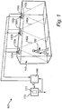
- Fig. 1 shows a lighting system 100 for controlling illumination of an area 110.
- the area 110 is illuminated by, e.g., three lighting devices 120a-c and presence of occupants (e.g. persons) 150 in the area 110 is monitored by, e.g., three presence sensors 130a-c (e.g. motion detectors, sound detectors, heat detectors or other types of presence sensors), each monitoring a part 140a-c of the area 110.
- three presence sensors 130a-c e.g. motion detectors, sound detectors, heat detectors or other types of presence sensors
- the area 110 is larger, is illuminated by a larger number of lighting devices 120a-c and is monitored by a larger number of presence sensors 130a-c.
- the number of presence sensors 130a-c may be different from the number of lighting devices 120a-c.
- a lighting controller 160 receives presence information from the presence sensors 130a-c and, for control of the lighting devices 120a-c, determines light settings d based on the received presence information and a particular lighting control strategy.
- the light settings d determined by the lighting controller 160 may comprise one dimming level for each of the lighting devices 120a-c.
- the lighting control strategy may be, e.g., a localized illumination rendering, in which occupied parts of the area 110, i.e. the part 140a occupied by the person 150, are to be illuminated more (intensely) than unoccupied parts, i.e. parts 140b-c.
- the light settings d determined by the lighting controller 160 may be dimming levels for the lighting devices 120a-c, said light settings d controlling a lighting device 120a, arranged to illuminate the occupied part 140a of the region 110, to operate at full capacity, while the light settings d may control the other lighting devices 120b-c to operate at e.g. half capacity to reduce power consumption.
- the occupant 150 moves to another part 140b of the area 110 (not shown in Fig.
- a presence sensor 120b will detect his/her presence and the lighting controller 160 will determine new light settings d, causing a lighting device 120b to be adapted to illuminate the newly occupied part 140b of the area 110 and to operate at full capacity while the other lighting devices 120a and 120b may operate, e.g., at half capacity.
- a lighting control analyzer 170 may be connected to the lighting controller 160.
- the method 600 may comprise receiving 630 the light settings d, for example regularly or as often as the light settings are updated by the lighting controller 160 (e.g. once a second, ten times a second, or a hundred times a second).
- the method 600 may comprise storing 640 the received light settings d, e.g., in a memory 171 arranged in the lighting control analyzer 170.
- the lighting control analyzer 170 has information about the lighting control strategy used by the lighting controller 160 to determine the light settings d based on the presence information.
- the method 600 may optionally comprise obtaining 620 this information, e.g., from the lighting controller 160.
- the method 600 may further comprise determining 650 occupancy behavior in the area, based on the received (and possibly also stored) light settings d and the lighting control strategy.
- the occupancy behavior may for example comprise information about how often occupants (persons) 150 occupy different parts 140a-c of the area 110 (this is referred to as occupancy levels), and/or information about locations that are normally occupied (this is referred to as occupant positions).
- the determination of the occupancy behavior of an area is described below in relation to Figs 2 to 5 .
- the method 600 may optionally comprise providing 660 information (or control parameters) P, based on the occupancy behavior, for control of, e.g., illumination of the area 110; heating, ventilation and/or air conditioning of the area 110; and/or the flow of sunlight in the area 110.
- the information P may be transmitted, e.g., to the lighting controller 160 or to other systems related to the area 110.
- Prior art methods of controlling various systems in buildings tend to use only local information available within a system.
- the above described way of controlling systems using relevant data from other systems (i.e. the information P) to improve performance may be advantageous compared to prior art methods. For instance, more energy efficient illumination from one lighting system may be obtained using lighting control information (e.g. the information P) from another lighting system.
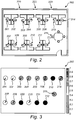
- Fig. 2 shows a schematic top view of an office area 200 which is illuminated by the lighting system 100 of Fig. 1 (not shown in Fig. 2 ), and in which occupancy behavior is to be determined/estimated by the lighting control analyzer 170 of Fig. 1 .
- the area 110 shown in Fig. 1 may be a subset of the office area 200 shown in Fig. 2 , and that in order for the lighting system 100 to illuminate the office area 200, it may comprise more lighting devices 120a-c and presence sensors 130a-c than shown in Fig. 1 .
- a plurality of lighting devices and presence sensors may be, e.g., evenly distributed in the office area 200.
- the office area 200 depicted in Fig. 2 as an example comprises a number of work stations or actual occupant positions 201-215, normally occupied by persons working in the office area 200. Occupant positions 201-215 are supposed to be located in chairs at desks distributed in the office area 200. Windows 220 are arranged along one of the walls of the office area 200 in this example.
- FIG. 3 shows a schematic top view of the office area 220 of Fig. 2 , with an example of actual occupancy levels and actual occupancy positions 201-215.
- the actual occupancy levels are indicated as regions, around each of which actual occupant positions 201-215 are shown, the regions being filled by different patterns. The different patterns indicate different values of the occupancy levels.
- the pattern around occupant positions 212 and 214 indicates high occupancy levels, which means that the occupant positions 212 and 214 are occupied by persons more often than other occupant positions, such as e.g. occupant positions 404 and 415 surrounded by a pattern indicating low occupancy levels.
- the occupancy levels may be measured using different scales.
- the scale from 0 to 1, shown in Fig. 3 is an example scale in which an occupancy level close to 1 indicates that the corresponding location is occupied during a large part of a usual working day.
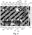
- FIG. 4 shows an example of occupancy levels and occupant positions in the office area of Fig. 2 , determined by the lighting control analyzer 170 of Fig. 1 .
- occupancy levels and occupant positions are examples of occupancy behavior and are the results of an attempt by the lighting control analyzer 170 to estimate the actual occupancy levels and occupant positions 201-215 depicted in Fig. 3 .
- Fig. 4 shows a schematic representation of an example of occupancy levels and occupant positions 401-417 in the office area 200 of Fig. 2 , determined by the lighting control analyzer 170.
- the lighting controller 160 determines the light settings d using a localized illumination rendering strategy in which the dimming levels of the lighting devices are determined to provide a specified higher level (e.g., 500 lux) around occupied locations and a lower level (e.g., 300 lux) elsewhere in the office area 200.
- a specified higher level e.g., 500 lux
- a lower level e.g., 300 lux
- the occupancy levels and occupant positions 401-417 may be determined by the lighting control analyzer 170, based on received dimming levels d, according to the following method:
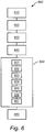
- the outline of the above method may be summarized with reference to Fig. 6 .
- the step of determining 650 the occupancy behavior may comprise determining 651 an illumination, based on a dimming level vector received at a certain time instant.
- the method 600 may optionally comprise obtaining 610 a mapping (or other information needed to perform said determining 651) between light settings for the lighting devices and the illumination provided by the lighting devices. Based on knowledge of the lighting control strategy (i.e. the localized illumination rendering), a momentary estimate of occupancy levels and occupant positions is made 652 based on the provided illumination.
- the step of determining 650 the occupancy behavior may comprise improving the estimation of occupancy levels 653 and occupant positions 654, based on building a distribution using further values of provided illuminations corresponding to other received dimming level vectors, for example 100 different dimming vectors (i.e. occupants of the office may possibly be at different locations at the time points corresponding to every one of these).
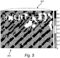
- FIG. 5 shows an example external light contribution (e.g. daylight contribution) and a light ingress location in the office area of Fig. 2 , both determined by the lighting control analyzer 170 of Fig. 1 .
- This determined external light contribution and this light ingress location are the results of an attempt by the lighting control analyzer 170 to estimate the actual external light contribution and light ingress location (windows 220) of the office area 200.
- Fig. 5 shows a schematic representation of daylight contribution to the illumination and a daylight ingress location (i.e. windows) 501 in the office area 200 of Fig. 2 , both estimated by the lighting control analyzer 170.
- the quantity D'(x, y) is a lower-bound daylight estimate.
- the above method may be summarized with reference to Fig. 6 .
- the step of determining 650 the occupancy behavior may comprise determining 655 an expected illumination of the area by the lighting devices, based on the determined occupancy levels/positions, i.e. 300 lux and 500 lux (scaled by I(x, y)/I max ) in unoccupied and occupied locations, respectively. It may further comprise comparing 656 the expected illumination with the actually provided illumination I(x, y) and estimating 657 light ingress locations, based on such comparisons for several time instants.
- the estimated daylight contribution is concentrated in the upper part of the office area 200 and suggests a daylight ingress location 501 along the upper wall of the office area 200. It is to be noted that the estimated daylight contribution may be measured using different scales.
- the scale from 0 to 1, shown in Fig. 5 is an example scale in which 1 corresponds to the highest estimated daylight contribution in Fig. 5 , and 0 corresponds to no estimated daylight contribution.
- Knowledge of occupancy levels, spatiotemporal occupancy patterns and daylight distribution may, e.g., be used to provide improved localized heating/cooling.
- heating/cooling conditions may be regulated in accordance with the number of occupants in close vicinity within an area, the amount of time an area has been occupied, and the proximity to a window source (which may be treated as a source of natural heat or cold, depending on weather conditions).
- this knowledge may be used to provide, on the one hand, improved blind control, such as, allow a larger ingress of daylight and simultaneously improve the outside view from the office when there is no occupant close to the windows.
- the lighting control analyzer receives light settings from multiple lighting systems (comprising lighting devices and lighting controllers), or where the lighting control analyzer receives light settings for control of a single lighting device adapted to illuminate different parts of an area by e.g. moving or rotating (or by the light output of the lighting device being e.g. directed or reflected to different parts of the area).
Landscapes
- Engineering & Computer Science (AREA)
- General Engineering & Computer Science (AREA)
- Chemical & Material Sciences (AREA)
- Combustion & Propulsion (AREA)
- Mechanical Engineering (AREA)
- Physics & Mathematics (AREA)
- Fuzzy Systems (AREA)
- Mathematical Physics (AREA)
- Signal Processing (AREA)
- General Physics & Mathematics (AREA)
- Automation & Control Theory (AREA)
- Circuit Arrangement For Electric Light Sources In General (AREA)
Applications Claiming Priority (2)
| Application Number | Priority Date | Filing Date | Title |
|---|---|---|---|
| US201361750002P | 2013-01-08 | 2013-01-08 | |
| PCT/IB2014/058029 WO2014108815A2 (en) | 2013-01-08 | 2014-01-03 | Lighting control analyzer |
Publications (2)
| Publication Number | Publication Date |
|---|---|
| EP2944160A2 EP2944160A2 (en) | 2015-11-18 |
| EP2944160B1 true EP2944160B1 (en) | 2020-09-16 |
Family
ID=49989867
Family Applications (1)
| Application Number | Title | Priority Date | Filing Date |
|---|---|---|---|
| EP14700794.2A Active EP2944160B1 (en) | 2013-01-08 | 2014-01-03 | Lighting control analyzer |
Country Status (5)
| Country | Link |
|---|---|
| US (1) | US9854644B2 (zh) |
| EP (1) | EP2944160B1 (zh) |
| JP (1) | JP6532824B2 (zh) |
| CN (1) | CN104885573B (zh) |
| WO (1) | WO2014108815A2 (zh) |
Families Citing this family (5)
| Publication number | Priority date | Publication date | Assignee | Title |
|---|---|---|---|---|
| US9585229B2 (en) * | 2014-05-13 | 2017-02-28 | Google Inc. | Anticipatory lighting from device screens based on user profile |
| CN107113944B (zh) * | 2014-10-28 | 2019-11-19 | 飞利浦灯具控股公司 | 用于控制照明系统的控制系统 |
| CN106793403B (zh) * | 2016-12-22 | 2018-10-30 | 上海诚唐展览展示有限公司 | 一种智能照明控制系统 |
| US11006504B2 (en) * | 2017-11-28 | 2021-05-11 | Signify Holding B.V. | Equivalent melanopic lux (EML) quotas |
| JP2021508934A (ja) * | 2018-01-02 | 2021-03-11 | シグニファイ ホールディング ビー ヴィSignify Holding B.V. | モーションセンサを備える照明デバイス |
Family Cites Families (9)
| Publication number | Priority date | Publication date | Assignee | Title |
|---|---|---|---|---|
| US5640143A (en) * | 1995-02-06 | 1997-06-17 | Mytech Corporation | Occupancy sensor and method of operating same |
| ES2373185T3 (es) * | 2007-03-01 | 2012-02-01 | Koninklijke Philips Electronics N.V. | Sistema de iluminación controlado por ordenador. |
| CN101400207B (zh) * | 2007-09-29 | 2012-07-25 | 财团法人工业技术研究院 | 自动调光系统与控制亮度的方法 |
| KR101520783B1 (ko) * | 2008-09-08 | 2015-05-18 | 삼성디스플레이 주식회사 | 표시 장치의 구동 방법, 이를 수행하기 위한 표시 장치 및 타이밍 컨트롤러 |
| CN201718081U (zh) * | 2010-05-07 | 2011-01-19 | 同济大学 | 智能led照明控制装置 |
| EP2578062B1 (en) * | 2010-06-03 | 2013-11-13 | Koninklijke Philips N.V. | Configuration unit and method for configuring a presence detection sensor |
| US8510255B2 (en) * | 2010-09-14 | 2013-08-13 | Nest Labs, Inc. | Occupancy pattern detection, estimation and prediction |
| US9357618B2 (en) | 2011-04-04 | 2016-05-31 | Koninklijke Philips N.V. | Device and method for illumination control of a plurality of light sources |
| US9618553B2 (en) * | 2011-09-15 | 2017-04-11 | University Of Washington Through Its Center For Commercialization | Systems and methods for sensing environmental changes using light sources as sensors |
-
2014
- 2014-01-03 WO PCT/IB2014/058029 patent/WO2014108815A2/en active Application Filing
- 2014-01-03 US US14/759,784 patent/US9854644B2/en active Active
- 2014-01-03 JP JP2015551240A patent/JP6532824B2/ja active Active
- 2014-01-03 EP EP14700794.2A patent/EP2944160B1/en active Active
- 2014-01-03 CN CN201480004322.1A patent/CN104885573B/zh active Active
Non-Patent Citations (1)
| Title |
|---|
| None * |
Also Published As
| Publication number | Publication date |
|---|---|
| WO2014108815A3 (en) | 2015-04-23 |
| US20150351198A1 (en) | 2015-12-03 |
| EP2944160A2 (en) | 2015-11-18 |
| WO2014108815A2 (en) | 2014-07-17 |
| CN104885573B (zh) | 2018-05-15 |
| US9854644B2 (en) | 2017-12-26 |
| JP6532824B2 (ja) | 2019-06-19 |
| JP2016506053A (ja) | 2016-02-25 |
| CN104885573A (zh) | 2015-09-02 |
Similar Documents
| Publication | Publication Date | Title |
|---|---|---|
| US11681263B2 (en) | Motorized window treatment monitoring and control | |
| US20220365491A1 (en) | Visible light sensor configured for glare detection and controlling motorized window treatments | |
| US11927057B2 (en) | Visible light sensor configured for glare detection and controlling motorized window treatments | |
| EP2944160B1 (en) | Lighting control analyzer | |
| US20150234369A1 (en) | Unified controller for integrated lighting, shading and thermostat control | |
| CN103814626B (zh) | 具有多点传感器校准的开环闭环集成日光和人造光控制 | |
| WO2013153480A2 (en) | A unifed controller for integrated lighting, shading and thermostat control | |
| US11830229B2 (en) | Visible light sensor configured for detection of glare conditions | |
| KR102044553B1 (ko) | 홈 에너지 관리 시스템 및 이의 실행 방법 | |
| JP5113568B2 (ja) | 環境制御システム | |
| JP5178003B2 (ja) | 電動ブラインドの制御装置 | |
| JP5440872B2 (ja) | 環境連動制御装置 | |
| JP2005037109A (ja) | 空調照明連動制御システム |
Legal Events
| Date | Code | Title | Description |
|---|---|---|---|
| PUAI | Public reference made under article 153(3) epc to a published international application that has entered the european phase |
Free format text: ORIGINAL CODE: 0009012 |
|
| AK | Designated contracting states |
Kind code of ref document: A2 Designated state(s): AL AT BE BG CH CY CZ DE DK EE ES FI FR GB GR HR HU IE IS IT LI LT LU LV MC MK MT NL NO PL PT RO RS SE SI SK SM TR |
|
| AX | Request for extension of the european patent |
Extension state: BA ME |
|
| 17P | Request for examination filed |
Effective date: 20151023 |
|
| RBV | Designated contracting states (corrected) |
Designated state(s): AL AT BE BG CH CY CZ DE DK EE ES FI FR GB GR HR HU IE IS IT LI LT LU LV MC MK MT NL NO PL PT RO RS SE SI SK SM TR |
|
| DAX | Request for extension of the european patent (deleted) | ||
| RAP1 | Party data changed (applicant data changed or rights of an application transferred) |
Owner name: PHILIPS LIGHTING HOLDING B.V. |
|
| RIN1 | Information on inventor provided before grant (corrected) |
Inventor name: CAICEDO FERNANDEZ, DAVID RICARDO Inventor name: PANDHARIPANDE, ASHISH VIJAY |
|
| STAA | Information on the status of an ep patent application or granted ep patent |
Free format text: STATUS: EXAMINATION IS IN PROGRESS |
|
| 17Q | First examination report despatched |
Effective date: 20180619 |
|
| RAP1 | Party data changed (applicant data changed or rights of an application transferred) |
Owner name: PHILIPS LIGHTING HOLDING B.V. |
|
| RAP1 | Party data changed (applicant data changed or rights of an application transferred) |
Owner name: SIGNIFY HOLDING B.V. |
|
| REG | Reference to a national code |
Ref country code: DE Ref legal event code: R079 Ref document number: 602014070212 Country of ref document: DE Free format text: PREVIOUS MAIN CLASS: H05B0037020000 Ipc: H05B0047115000 |
|
| GRAP | Despatch of communication of intention to grant a patent |
Free format text: ORIGINAL CODE: EPIDOSNIGR1 |
|
| STAA | Information on the status of an ep patent application or granted ep patent |
Free format text: STATUS: GRANT OF PATENT IS INTENDED |
|
| RIC1 | Information provided on ipc code assigned before grant |
Ipc: H05B 47/115 20200101AFI20200402BHEP |
|
| INTG | Intention to grant announced |
Effective date: 20200424 |
|
| GRAS | Grant fee paid |
Free format text: ORIGINAL CODE: EPIDOSNIGR3 |
|
| GRAA | (expected) grant |
Free format text: ORIGINAL CODE: 0009210 |
|
| STAA | Information on the status of an ep patent application or granted ep patent |
Free format text: STATUS: THE PATENT HAS BEEN GRANTED |
|
| AK | Designated contracting states |
Kind code of ref document: B1 Designated state(s): AL AT BE BG CH CY CZ DE DK EE ES FI FR GB GR HR HU IE IS IT LI LT LU LV MC MK MT NL NO PL PT RO RS SE SI SK SM TR |
|
| REG | Reference to a national code |
Ref country code: GB Ref legal event code: FG4D |
|
| REG | Reference to a national code |
Ref country code: CH Ref legal event code: EP |
|
| REG | Reference to a national code |
Ref country code: DE Ref legal event code: R096 Ref document number: 602014070212 Country of ref document: DE |
|
| REG | Reference to a national code |
Ref country code: IE Ref legal event code: FG4D |
|
| REG | Reference to a national code |
Ref country code: AT Ref legal event code: REF Ref document number: 1315387 Country of ref document: AT Kind code of ref document: T Effective date: 20201015 |
|
| PG25 | Lapsed in a contracting state [announced via postgrant information from national office to epo] |
Ref country code: HR Free format text: LAPSE BECAUSE OF FAILURE TO SUBMIT A TRANSLATION OF THE DESCRIPTION OR TO PAY THE FEE WITHIN THE PRESCRIBED TIME-LIMIT Effective date: 20200916 Ref country code: BG Free format text: LAPSE BECAUSE OF FAILURE TO SUBMIT A TRANSLATION OF THE DESCRIPTION OR TO PAY THE FEE WITHIN THE PRESCRIBED TIME-LIMIT Effective date: 20201216 Ref country code: GR Free format text: LAPSE BECAUSE OF FAILURE TO SUBMIT A TRANSLATION OF THE DESCRIPTION OR TO PAY THE FEE WITHIN THE PRESCRIBED TIME-LIMIT Effective date: 20201217 Ref country code: SE Free format text: LAPSE BECAUSE OF FAILURE TO SUBMIT A TRANSLATION OF THE DESCRIPTION OR TO PAY THE FEE WITHIN THE PRESCRIBED TIME-LIMIT Effective date: 20200916 Ref country code: NO Free format text: LAPSE BECAUSE OF FAILURE TO SUBMIT A TRANSLATION OF THE DESCRIPTION OR TO PAY THE FEE WITHIN THE PRESCRIBED TIME-LIMIT Effective date: 20201216 Ref country code: FI Free format text: LAPSE BECAUSE OF FAILURE TO SUBMIT A TRANSLATION OF THE DESCRIPTION OR TO PAY THE FEE WITHIN THE PRESCRIBED TIME-LIMIT Effective date: 20200916 |
|
| REG | Reference to a national code |
Ref country code: AT Ref legal event code: MK05 Ref document number: 1315387 Country of ref document: AT Kind code of ref document: T Effective date: 20200916 |
|
| REG | Reference to a national code |
Ref country code: NL Ref legal event code: MP Effective date: 20200916 |
|
| PG25 | Lapsed in a contracting state [announced via postgrant information from national office to epo] |
Ref country code: RS Free format text: LAPSE BECAUSE OF FAILURE TO SUBMIT A TRANSLATION OF THE DESCRIPTION OR TO PAY THE FEE WITHIN THE PRESCRIBED TIME-LIMIT Effective date: 20200916 Ref country code: LV Free format text: LAPSE BECAUSE OF FAILURE TO SUBMIT A TRANSLATION OF THE DESCRIPTION OR TO PAY THE FEE WITHIN THE PRESCRIBED TIME-LIMIT Effective date: 20200916 |
|
| REG | Reference to a national code |
Ref country code: LT Ref legal event code: MG4D |
|
| PG25 | Lapsed in a contracting state [announced via postgrant information from national office to epo] |
Ref country code: EE Free format text: LAPSE BECAUSE OF FAILURE TO SUBMIT A TRANSLATION OF THE DESCRIPTION OR TO PAY THE FEE WITHIN THE PRESCRIBED TIME-LIMIT Effective date: 20200916 Ref country code: CZ Free format text: LAPSE BECAUSE OF FAILURE TO SUBMIT A TRANSLATION OF THE DESCRIPTION OR TO PAY THE FEE WITHIN THE PRESCRIBED TIME-LIMIT Effective date: 20200916 Ref country code: SM Free format text: LAPSE BECAUSE OF FAILURE TO SUBMIT A TRANSLATION OF THE DESCRIPTION OR TO PAY THE FEE WITHIN THE PRESCRIBED TIME-LIMIT Effective date: 20200916 Ref country code: RO Free format text: LAPSE BECAUSE OF FAILURE TO SUBMIT A TRANSLATION OF THE DESCRIPTION OR TO PAY THE FEE WITHIN THE PRESCRIBED TIME-LIMIT Effective date: 20200916 Ref country code: NL Free format text: LAPSE BECAUSE OF FAILURE TO SUBMIT A TRANSLATION OF THE DESCRIPTION OR TO PAY THE FEE WITHIN THE PRESCRIBED TIME-LIMIT Effective date: 20200916 Ref country code: LT Free format text: LAPSE BECAUSE OF FAILURE TO SUBMIT A TRANSLATION OF THE DESCRIPTION OR TO PAY THE FEE WITHIN THE PRESCRIBED TIME-LIMIT Effective date: 20200916 Ref country code: PT Free format text: LAPSE BECAUSE OF FAILURE TO SUBMIT A TRANSLATION OF THE DESCRIPTION OR TO PAY THE FEE WITHIN THE PRESCRIBED TIME-LIMIT Effective date: 20210118 |
|
| PG25 | Lapsed in a contracting state [announced via postgrant information from national office to epo] |
Ref country code: IS Free format text: LAPSE BECAUSE OF FAILURE TO SUBMIT A TRANSLATION OF THE DESCRIPTION OR TO PAY THE FEE WITHIN THE PRESCRIBED TIME-LIMIT Effective date: 20210116 Ref country code: PL Free format text: LAPSE BECAUSE OF FAILURE TO SUBMIT A TRANSLATION OF THE DESCRIPTION OR TO PAY THE FEE WITHIN THE PRESCRIBED TIME-LIMIT Effective date: 20200916 Ref country code: ES Free format text: LAPSE BECAUSE OF FAILURE TO SUBMIT A TRANSLATION OF THE DESCRIPTION OR TO PAY THE FEE WITHIN THE PRESCRIBED TIME-LIMIT Effective date: 20200916 Ref country code: AL Free format text: LAPSE BECAUSE OF FAILURE TO SUBMIT A TRANSLATION OF THE DESCRIPTION OR TO PAY THE FEE WITHIN THE PRESCRIBED TIME-LIMIT Effective date: 20200916 Ref country code: AT Free format text: LAPSE BECAUSE OF FAILURE TO SUBMIT A TRANSLATION OF THE DESCRIPTION OR TO PAY THE FEE WITHIN THE PRESCRIBED TIME-LIMIT Effective date: 20200916 |
|
| REG | Reference to a national code |
Ref country code: DE Ref legal event code: R097 Ref document number: 602014070212 Country of ref document: DE |
|
| PG25 | Lapsed in a contracting state [announced via postgrant information from national office to epo] |
Ref country code: SK Free format text: LAPSE BECAUSE OF FAILURE TO SUBMIT A TRANSLATION OF THE DESCRIPTION OR TO PAY THE FEE WITHIN THE PRESCRIBED TIME-LIMIT Effective date: 20200916 |
|
| PLBE | No opposition filed within time limit |
Free format text: ORIGINAL CODE: 0009261 |
|
| STAA | Information on the status of an ep patent application or granted ep patent |
Free format text: STATUS: NO OPPOSITION FILED WITHIN TIME LIMIT |
|
| 26N | No opposition filed |
Effective date: 20210617 |
|
| PG25 | Lapsed in a contracting state [announced via postgrant information from national office to epo] |
Ref country code: SI Free format text: LAPSE BECAUSE OF FAILURE TO SUBMIT A TRANSLATION OF THE DESCRIPTION OR TO PAY THE FEE WITHIN THE PRESCRIBED TIME-LIMIT Effective date: 20200916 Ref country code: DK Free format text: LAPSE BECAUSE OF FAILURE TO SUBMIT A TRANSLATION OF THE DESCRIPTION OR TO PAY THE FEE WITHIN THE PRESCRIBED TIME-LIMIT Effective date: 20200916 Ref country code: MC Free format text: LAPSE BECAUSE OF FAILURE TO SUBMIT A TRANSLATION OF THE DESCRIPTION OR TO PAY THE FEE WITHIN THE PRESCRIBED TIME-LIMIT Effective date: 20200916 |
|
| REG | Reference to a national code |
Ref country code: CH Ref legal event code: PL |
|
| PG25 | Lapsed in a contracting state [announced via postgrant information from national office to epo] |
Ref country code: LU Free format text: LAPSE BECAUSE OF NON-PAYMENT OF DUE FEES Effective date: 20210103 |
|
| REG | Reference to a national code |
Ref country code: BE Ref legal event code: MM Effective date: 20210131 |
|
| PG25 | Lapsed in a contracting state [announced via postgrant information from national office to epo] |
Ref country code: IT Free format text: LAPSE BECAUSE OF FAILURE TO SUBMIT A TRANSLATION OF THE DESCRIPTION OR TO PAY THE FEE WITHIN THE PRESCRIBED TIME-LIMIT Effective date: 20200916 |
|
| PG25 | Lapsed in a contracting state [announced via postgrant information from national office to epo] |
Ref country code: CH Free format text: LAPSE BECAUSE OF NON-PAYMENT OF DUE FEES Effective date: 20210131 Ref country code: LI Free format text: LAPSE BECAUSE OF NON-PAYMENT OF DUE FEES Effective date: 20210131 |
|
| PG25 | Lapsed in a contracting state [announced via postgrant information from national office to epo] |
Ref country code: IE Free format text: LAPSE BECAUSE OF NON-PAYMENT OF DUE FEES Effective date: 20210103 |
|
| PG25 | Lapsed in a contracting state [announced via postgrant information from national office to epo] |
Ref country code: BE Free format text: LAPSE BECAUSE OF NON-PAYMENT OF DUE FEES Effective date: 20210131 |
|
| PGFP | Annual fee paid to national office [announced via postgrant information from national office to epo] |
Ref country code: FR Payment date: 20230124 Year of fee payment: 10 |
|
| PG25 | Lapsed in a contracting state [announced via postgrant information from national office to epo] |
Ref country code: HU Free format text: LAPSE BECAUSE OF FAILURE TO SUBMIT A TRANSLATION OF THE DESCRIPTION OR TO PAY THE FEE WITHIN THE PRESCRIBED TIME-LIMIT; INVALID AB INITIO Effective date: 20140103 |
|
| P01 | Opt-out of the competence of the unified patent court (upc) registered |
Effective date: 20230421 |
|
| PG25 | Lapsed in a contracting state [announced via postgrant information from national office to epo] |
Ref country code: CY Free format text: LAPSE BECAUSE OF FAILURE TO SUBMIT A TRANSLATION OF THE DESCRIPTION OR TO PAY THE FEE WITHIN THE PRESCRIBED TIME-LIMIT Effective date: 20200916 |
|
| PG25 | Lapsed in a contracting state [announced via postgrant information from national office to epo] |
Ref country code: MK Free format text: LAPSE BECAUSE OF FAILURE TO SUBMIT A TRANSLATION OF THE DESCRIPTION OR TO PAY THE FEE WITHIN THE PRESCRIBED TIME-LIMIT Effective date: 20200916 |
|
| PGFP | Annual fee paid to national office [announced via postgrant information from national office to epo] |
Ref country code: DE Payment date: 20240328 Year of fee payment: 11 Ref country code: GB Payment date: 20240123 Year of fee payment: 11 |