EP2943406B2 - Dispositif de protection contre la foudre et son procede de realisation - Google Patents
Dispositif de protection contre la foudre et son procede de realisation Download PDFInfo
- Publication number
- EP2943406B2 EP2943406B2 EP14703119.9A EP14703119A EP2943406B2 EP 2943406 B2 EP2943406 B2 EP 2943406B2 EP 14703119 A EP14703119 A EP 14703119A EP 2943406 B2 EP2943406 B2 EP 2943406B2
- Authority
- EP
- European Patent Office
- Prior art keywords
- coating
- protection device
- lightning protection
- lightning
- conductive
- Prior art date
- Legal status (The legal status is an assumption and is not a legal conclusion. Google has not performed a legal analysis and makes no representation as to the accuracy of the status listed.)
- Active
Links
Images
Classifications
-
- H—ELECTRICITY
- H02—GENERATION; CONVERSION OR DISTRIBUTION OF ELECTRIC POWER
- H02G—INSTALLATION OF ELECTRIC CABLES OR LINES, OR OF COMBINED OPTICAL AND ELECTRIC CABLES OR LINES
- H02G13/00—Installations of lightning conductors; Fastening thereof to supporting structure
- H02G13/80—Discharge by conduction or dissipation, e.g. rods, arresters, spark gaps
-
- B—PERFORMING OPERATIONS; TRANSPORTING
- B64—AIRCRAFT; AVIATION; COSMONAUTICS
- B64D—EQUIPMENT FOR FITTING IN OR TO AIRCRAFT; FLIGHT SUITS; PARACHUTES; ARRANGEMENT OR MOUNTING OF POWER PLANTS OR PROPULSION TRANSMISSIONS IN AIRCRAFT
- B64D45/00—Aircraft indicators or protectors not otherwise provided for
- B64D45/02—Lightning protectors; Static dischargers
-
- B—PERFORMING OPERATIONS; TRANSPORTING
- B64—AIRCRAFT; AVIATION; COSMONAUTICS
- B64G—COSMONAUTICS; VEHICLES OR EQUIPMENT THEREFOR
- B64G1/00—Cosmonautic vehicles
- B64G1/22—Parts of, or equipment specially adapted for fitting in or to, cosmonautic vehicles
- B64G1/226—Special coatings for spacecraft
-
- B—PERFORMING OPERATIONS; TRANSPORTING
- B64—AIRCRAFT; AVIATION; COSMONAUTICS
- B64G—COSMONAUTICS; VEHICLES OR EQUIPMENT THEREFOR
- B64G1/00—Cosmonautic vehicles
- B64G1/22—Parts of, or equipment specially adapted for fitting in or to, cosmonautic vehicles
- B64G1/52—Protection, safety or emergency devices; Survival aids
- B64G1/58—Thermal protection, e.g. heat shields
-
- C—CHEMISTRY; METALLURGY
- C09—DYES; PAINTS; POLISHES; NATURAL RESINS; ADHESIVES; COMPOSITIONS NOT OTHERWISE PROVIDED FOR; APPLICATIONS OF MATERIALS NOT OTHERWISE PROVIDED FOR
- C09D—COATING COMPOSITIONS, e.g. PAINTS, VARNISHES OR LACQUERS; FILLING PASTES; CHEMICAL PAINT OR INK REMOVERS; INKS; CORRECTING FLUIDS; WOODSTAINS; PASTES OR SOLIDS FOR COLOURING OR PRINTING; USE OF MATERIALS THEREFOR
- C09D5/00—Coating compositions, e.g. paints, varnishes or lacquers, characterised by their physical nature or the effects produced; Filling pastes
- C09D5/24—Electrically-conducting paints
-
- F—MECHANICAL ENGINEERING; LIGHTING; HEATING; WEAPONS; BLASTING
- F02—COMBUSTION ENGINES; HOT-GAS OR COMBUSTION-PRODUCT ENGINE PLANTS
- F02C—GAS-TURBINE PLANTS; AIR INTAKES FOR JET-PROPULSION PLANTS; CONTROLLING FUEL SUPPLY IN AIR-BREATHING JET-PROPULSION PLANTS
- F02C7/00—Features, components parts, details or accessories, not provided for in, or of interest apart form groups F02C1/00 - F02C6/00; Air intakes for jet-propulsion plants
- F02C7/24—Heat or noise insulation
- F02C7/25—Fire protection or prevention
-
- F—MECHANICAL ENGINEERING; LIGHTING; HEATING; WEAPONS; BLASTING
- F02—COMBUSTION ENGINES; HOT-GAS OR COMBUSTION-PRODUCT ENGINE PLANTS
- F02K—JET-PROPULSION PLANTS
- F02K1/00—Plants characterised by the form or arrangement of the jet pipe or nozzle; Jet pipes or nozzles peculiar thereto
- F02K1/78—Other construction of jet pipes
-
- F—MECHANICAL ENGINEERING; LIGHTING; HEATING; WEAPONS; BLASTING
- F02—COMBUSTION ENGINES; HOT-GAS OR COMBUSTION-PRODUCT ENGINE PLANTS
- F02K—JET-PROPULSION PLANTS
- F02K9/00—Rocket-engine plants, i.e. plants carrying both fuel and oxidant therefor; Control thereof
- F02K9/97—Rocket nozzles
- F02K9/974—Nozzle- linings; Ablative coatings
-
- H—ELECTRICITY
- H05—ELECTRIC TECHNIQUES NOT OTHERWISE PROVIDED FOR
- H05F—STATIC ELECTRICITY; NATURALLY-OCCURRING ELECTRICITY
- H05F1/00—Preventing the formation of electrostatic charges
- H05F1/02—Preventing the formation of electrostatic charges by surface treatment
-
- B—PERFORMING OPERATIONS; TRANSPORTING
- B64—AIRCRAFT; AVIATION; COSMONAUTICS
- B64G—COSMONAUTICS; VEHICLES OR EQUIPMENT THEREFOR
- B64G1/00—Cosmonautic vehicles
- B64G1/22—Parts of, or equipment specially adapted for fitting in or to, cosmonautic vehicles
- B64G1/40—Arrangements or adaptations of propulsion systems
-
- F—MECHANICAL ENGINEERING; LIGHTING; HEATING; WEAPONS; BLASTING
- F05—INDEXING SCHEMES RELATING TO ENGINES OR PUMPS IN VARIOUS SUBCLASSES OF CLASSES F01-F04
- F05D—INDEXING SCHEME FOR ASPECTS RELATING TO NON-POSITIVE-DISPLACEMENT MACHINES OR ENGINES, GAS-TURBINES OR JET-PROPULSION PLANTS
- F05D2300/00—Materials; Properties thereof
- F05D2300/60—Properties or characteristics given to material by treatment or manufacturing
- F05D2300/611—Coating
Definitions
- the present invention relates to the field of lightning protection intended for use in high temperature environments.
- a particular but not exclusive field of the present invention is that of lightning protection of hot parts present in thrusters for space launchers, tactics, etc. or in aeronautical engines.
- the thrusters fitted to this type of launchers or the aftermarket parts of aeronautical engines are liable to be struck by lightning during the flight.
- the blasted part (s) are made of a non-conductive material such as a composite material or when these are covered with a dielectric material, their structure can be seriously damaged by the impulse and continuous components of the electric arc created by lightning.
- the present invention therefore aims to provide a solution to protect against lightning non-conductive structures or covered with a dielectric, and this reliably in high temperature environment.
- This provides effective protection against lightning attack, in particular due to the use of a conductive paint capable of quickly discharging a large amount of current during a lightning strike.
- the integrity of the protection device of the invention is preserved even when it is used on structures exposed to significant thermal fluxes.
- the protective coating is also electrically conductive, it contributes to the overall electrical efficiency of the device by ensuring electrical continuity between the exposed surface of the device and the conductive paint.
- the device can adapt to any type of geometry, even complex.
- the second coating has a thermal conductivity less than 0.1 Wm -1 .K -1 .
- the second coating has a surface resistivity less than 200 ohms.
- the invention also relates to a lightning sensitive structure intended to operate in high temperature environments, characterized in that at least part of said structure is provided with a lightning protection device according to the invention.
- the structure corresponds in particular to a nozzle, an after-body or a thruster shell.
- the second coating has a thermal conductivity less than 0.1 Wm -1 .K -1 .
- the second coating has a surface resistivity less than 200 ohms.
- the method of the invention can also be advantageously used for repairing the coating according to the invention, this repair then being particularly easy.
- the lightning protection device of the invention is preferably, but not exclusively, intended to be used on any structure made of an electrically non-conductive material or covered on its surface or surfaces to be protected with a material or layer of electrical insulation, as is the case for example with thermal protection coatings used on launchers, the structure also being intended for use in high temperature environments.
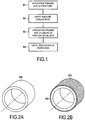
- a method of manufacturing a lightning protection device according to an embodiment of the invention is described in relation to the figures 1 and 2A to 2E .
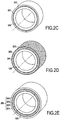
- the figure 2A represents an axisymmetric part 100 corresponding to a structure to be protected against lightning.
- the part 100 can be made of a thermostructural composite material that is not electrically conductive corresponding, for example, to a sub-assembly of a rocket engine or an aeronautical engine exposed to the high temperatures generated by the hot gases coming from the engine.
- the part 100 is made of a silicon carbide / silicon carbide (SiC / SiC) composite material which, in known manner, is a material formed from a reinforcement of SiC fibers densified by an SiC matrix.
- Thermostructural composite materials such as the SiC / SiC material, are characterized by their high mechanical properties which make them suitable for constituting structural parts and by their ability to maintain these mechanical properties at high temperatures.
- the part 100 is liable to be struck by lightning.
- the electric arc thus formed can lead to deterioration or destruction of the part (direct or indirect effects).
- a lightning protection device capable of withstanding high temperatures is formed on the external surface of the part 100 which here corresponds to the part of the part 100 to be protected against lightning.
- the production of the protection device begins with the deposition of a layer of metallic or electrically conductive paint 202, hereinafter called “conductive paint”, on the exterior surface of the part 100 to be protected (step S2, figure 2C ).
- a layer of a primer 201 for example an adhesion primer of the silane / ethanol type, is previously deposited on the surface of the part 100 in order to promote the adhesion of the conductive paint (step S1, figure 2B ).
- the prior deposition of a primer is not necessary and the conductive paint can be directly deposited on the surface of the part.
- the conductive paint, and any primer can be deposited by pneumatic spraying or by manual removal.
- the conductive paint may consist of an acrylic resin in which pigments based on metallic particles have been incorporated, such as, for example, silver, aluminum, copper particles, etc., the paint possibly being diluted in ketone solvents before application.
- Such a paint composition is in particular present in the product MAPELEC® SSS-47 or MAPELEC® SSS-02 (acrylic resin, silver pigment and mixtures of ketone solvents) sold by the company MAP.
- the production of the protection device continues by depositing a protective coating 204 on the layer of conductive paint 202 (step S4, figure 2E ).
- the protective coating 204 is both thermally insulating to protect the conductive paint from the surrounding heat fluxes and electrically conductive to promote electrical conduction with the paint.
- the protective coating 205 preferably has a thermal conductivity less than 0.1 Wm -1 .K -1 and a surface resistivity (or also called surface resistivity) less than 200 ohms (or 200 ohms per square). It can be deposited in several successive layers in order to obtain the desired thickness and, consequently, the target surface conductivity.
- the protective coating 205 can in particular be produced from a silicone resin charged with electrically conductive particles such as silver particles or a mixture of functionalized silicone polymers, a conductive charge (QS 1123 Elec LD) and ketone solvent.
- a layer of a primer 203 for example an epoxy primer loaded with electrically conductive particles or a primer consisting of a mixture of functionalized silanes and ethanol available under the reference MAPSIL® P255 of the MAP company, is previously deposited on the layer of conductive paint 202 in order to promote the adhesion of the protective coating 204 (step S3, 2D figure ).
- the thickness of the conductive layer can be between 30 ⁇ m and 60 ⁇ m while the primary (s) can each have a thickness of approximately 1 mm.
- the second coating protecting the first coating from the surrounding thermal fluxes may have a thickness of between 1 mm and 5 mm.
Landscapes
- Engineering & Computer Science (AREA)
- Chemical & Material Sciences (AREA)
- Combustion & Propulsion (AREA)
- Aviation & Aerospace Engineering (AREA)
- Remote Sensing (AREA)
- Mechanical Engineering (AREA)
- General Engineering & Computer Science (AREA)
- Emergency Medicine (AREA)
- General Health & Medical Sciences (AREA)
- Health & Medical Sciences (AREA)
- Critical Care (AREA)
- Organic Chemistry (AREA)
- Life Sciences & Earth Sciences (AREA)
- Wood Science & Technology (AREA)
- Materials Engineering (AREA)
- Physics & Mathematics (AREA)
- Thermal Sciences (AREA)
- Paints Or Removers (AREA)
- Elimination Of Static Electricity (AREA)
- Application Of Or Painting With Fluid Materials (AREA)
- Laminated Bodies (AREA)
- Thermistors And Varistors (AREA)
Description
- La présente invention se rapporte au domaine des protections contre la foudre destinées à être utilisées dans des environnements haute température. Un domaine particulier mais non exclusif de la présente invention est celui de la protection contre la foudre des parties chaudes présentes dans les propulseurs pour lanceurs spatiaux, tactiques, etc. ou dans les moteurs aéronautiques.
- En effet, les propulseurs équipant ce type de lanceurs ou les pièces d'arrière-corps de moteurs aéronautiques sont susceptibles de se faire foudroyer durant le vol. Lorsque la ou les parties foudroyées sont en un matériau non conducteur tel qu'un matériau composite ou lorsque celles-ci sont recouvertes d'un matériau diélectrique, leur structure peut être gravement endommagée par les composantes impulsionnelles et continues de l'arc électrique créé par la foudre.
- Il existe actuellement plusieurs techniques de protection contre la foudre dont les objectifs principaux sont de privilégier la circulation du courant de foudre dans la protection plutôt que dans la structure à protéger et d'augmenter rapidement la taille du pied d'arc de foudre de façon à réduire les contraintes thermiques et mécaniques.
- Parmi les solutions existantes, on trouve des revêtements de protection contre la foudre qui sont constitués de :
- tissus métalliques fixés sur la surface de la pièce à protéger,
- grilles métalliques déployée à partir d'une feuille de métal munies de fentes et étirée pour former une grille également fixée sur la surface de la pièce à protéger,
- couches conductrices réalisées par dépôts de particules métalliques, par exemple des particules de nickel, sur la surface de la pièce à protéger afin d'augmenter la conductivité de cette dernière,
- fibres métalliques directement tissées dans la texture fibreuse du renfort de la pièce en matériau composite à protéger afin de former une multitude de petites pointes en surface de la pièce aptes à disperser le pied d'arc foudre.
- Un dispositif de protection connu est décrit dans le document
EP 1 473 227 A2 . - Cependant, ces différents revêtements présentent certains inconvénients dont le principal est d'avoir une faible tenue en température. En outre, certains de ces revêtements sont difficiles à mettre en oeuvre sur des structures à géométrie complexe.
- Ces solutions présentent également l'inconvénient d'être difficilement réparables.
- La présente invention a, par conséquent, pour but de proposer une solution pour protéger contre la foudre des structures non conductrices ou recouvertes d'un diélectrique, et ce de façon fiable en environnement haute température.
- A cet effet, l'invention propose un dispositif de protection contre la foudre destiné à être posé sur une structure à protéger et comprenant au moins :
- un premier revêtement comprenant au moins une couche de peinture conductrice,
- un deuxième revêtement disposé sur l'ensemble du premier revêtement et comprenant un matériau thermiquement isolant et électriquement conducteur.
- On dispose ainsi d'une protection efficace contre l'agression foudre, en particulier en raison de l'utilisation d'une peinture conductrice capable d'évacuer rapidement une quantité importante de courant lors d'un foudroiement.
- En outre, grâce à la présence d'un deuxième revêtement thermiquement isolant, l'intégrité du dispositif de protection de l'invention est préservée même lorsqu'il est utilisé sur des structures exposées à des flux thermiques importants. Le revêtement de protection étant également électriquement conducteur, il contribue à l'efficacité électrique globale du dispositif en assurant une continuité électrique entre la surface exposée du dispositif et la peinture conductrice.
- Par ailleurs, de par sa conception, le dispositif peut s'adapter à tout type de géométries même complexes.
- Selon un premier aspect du dispositif de l'invention, le deuxième revêtement présente une conductivité thermique inférieure à 0,1 W.m-1.K-1.
- Selon un deuxième aspect du dispositif de l'invention, le deuxième revêtement présente une résistivité superficielle inférieure à 200 ohms.
- L'invention concerne également une structure sensible à la foudre destinée à fonctionner dans des environnements haute température, caractérisée en ce qu'au moins une partie de ladite structure est munie d'un dispositif de protection contre la foudre selon l'invention. La structure correspond notamment à une tuyère, un arrière-corps ou une virole de propulseur.
- L'invention a encore pour objet un procédé de réalisation d'un dispositif de protection contre la foudre sur une structure à protéger, ledit procédé comprenant au moins :
- le dépôt sur la structure à protéger d'un premier revêtement comprenant au moins une couche de peinture conductrice,
- le dépôt d'un deuxième revêtement sur l'ensemble du premier revêtement comprenant un matériau thermiquement isolant et électriquement conducteur.
- Selon un premier aspect du procédé de l'invention, le deuxième revêtement présente une conductivité thermique inférieure à 0,1 W.m-1.K-1.
- Selon un deuxième aspect du procédé de l'invention, le deuxième revêtement présente une résistivité superficielle inférieure à 200 ohms.
- Le procédé de l'invention peut en outre être également utilisé avantageusement pour la réparation du revêtement selon l'invention, cette réparation étant alors particulièrement aisée.
- D'autres caractéristiques et avantages de l'invention ressortiront de la description suivante de modes particuliers de réalisation de l'invention, donnés à titre d'exemples non limitatifs, en référence aux dessins annexés, sur lesquels :
- la
figure 1 est un organigramme des étapes d'un procédé de fabrication d'un dispositif de protection contre la foudre de l'invention illustré dans lesfigures 2A à 2E , - les
figures 2A à 2E sont des vues schématiques d'un procédé de fabrication d'un dispositif de protection contre la foudre conformément à un mode de réalisation de l'invention. - Le dispositif de protection contre la foudre de l'invention est de préférence, mais non exclusivement, destiné à être utilisé sur toute structure réalisée en un matériau non conducteur électrique ou recouverte sur sa ou ses surfaces à protéger d'un matériau ou couche d'isolation électrique, comme c'est le cas par exemple des revêtements de protection thermique utilisés sur les lanceurs, la structure étant en outre destinée à être utilisée dans des environnements haute température.
- Un procédé de fabrication d'un dispositif de protection contre la foudre conforme à un mode de réalisation de l'invention est décrit en relation avec les
figures 1 et2A à 2E . - La
figure 2A représente une pièce axisymétrique 100 correspondant à une structure à protéger contre la foudre. La pièce 100 peut être réalisée en un matériau composite thermostructural non conducteur électrique correspondant, par exemple, à un sous-ensemble de moteur-fusée ou de moteur aéronautique exposé aux fortes températures générées par les gaz chauds issus du moteur. - Par exemple, la pièce 100 est réalisée en matériau composite carbure de silicium/carbure de silicium (SiC/SiC) qui, de façon connue, est un matériau formé d'un renfort en fibres de SiC densifié par une matrice SiC. Les matériaux composites thermostructuraux, comme le matériau SiC/SiC, sont caractérisés par leurs propriétés mécaniques élevées qui les rendent aptes à constituer des pièces de structure et par leur capacité à conserver ces propriétés mécaniques à des températures élevées.
- La pièce 100, dont la surface externe est constituée d'un matériau non conducteur électrique, est susceptible d'être foudroyée. En cas de foudroiement de la pièce ou de l'ensemble dans laquelle la pièce est intégrée, l'arc électrique ainsi formé peut conduire à la détérioration ou à la destruction de la pièce (effets directs ou indirects). Il en est de même pour les revêtements diélectriques présents à la surface de structures à protéger.
- A cet effet et conformément à un mode de réalisation de l'invention, un dispositif de protection contre la foudre apte à résister aux températures élevées est formé sur la surface extérieure de la pièce 100 qui correspond ici à la partie de la pièce 100 à protéger contre la foudre.
- La réalisation du dispositif de protection débute par le dépôt d'une couche de peinture métallique ou électro-conductrice 202, appelée dans la suite du texte « peinture conductrice », sur la surface extérieure de la pièce 100 à protéger (étape S2,
figure 2C ). Dans l'exemple décrit ici, une couche d'un primaire 201, par exemple un primaire d'adhérence de type silane/éthanol, est préalablement déposée sur la surface de la pièce 100 afin de favoriser l'adhésion de la peinture conductrice (étape S1,figure 2B ). Toutefois, lorsque la pièce à protéger présente un état de surface compatible avec l'accrochage d'une peinture métallique, le dépôt préalable d'un primaire n'est pas nécessaire et la peinture conductrice peut être directement déposée sur la surface de la pièce. - La peinture conductrice, et le primaire éventuel, peuvent être déposés par pulvérisation pneumatique ou par dépose manuelle. La peinture conductrice peut être constituée d'une résine acrylique dans laquelle ont été incorporés des pigments à base de particules métalliques, comme, par exemple, des particules d'argent, d'aluminium, de cuivre, etc., la peinture pouvant être éventuellement diluée dans des solvants cétoniques avant application. Une telle composition de peinture est notamment présente dans le produit MAPELEC® SSS-47 ou MAPELEC® SSS-02 (résine acrylique, pigment argent et mélanges de solvants cétoniques) commercialisé par la société MAP.
- En outre, plusieurs couches de peinture conductrice peuvent être déposées consécutivement afin d'obtenir l'épaisseur de couche désirée et, par conséquent, la valeur de conductivité surfacique visée.
- La réalisation du dispositif de protection se poursuit par le dépôt d'un revêtement de protection 204 sur la couche de peinture conductrice 202 (étape S4,
figure 2E ). Le revêtement de protection 204 est à la fois thermiquement isolant pour protéger la peinture conductrice des flux thermiques environnants et électriquement conducteur pour favoriser la conduction électrique avec la peinture. Le revêtement de protection 205 présente de préférence une conductivité thermique inférieure à 0,1 W.m-1.K-1 et une résistivité superficielle (ou encore appelée résistivité de surface) inférieure à 200 ohms (ou 200 ohms par carré). Il peut être déposé en plusieurs couches successives afin d'obtenir l'épaisseur désirée et, par conséquent, la conductivité surfacique visée. Le revêtement de protection 205 peut être notamment réalisé à partir d'une résine silicone chargée de particules électro-conductrices comme des particules d'argent ou d'un mélange de polymères silicones fonctionnalisés, d'une charge conductrice (QS 1123 Elec LD) et de solvant cétoniques. - Dans l'exemple décrit ici, une couche d'un primaire 203, par exemple un primaire époxy chargé de particules électro-conductrices ou un primaire constitué d'un mélange de silanes fonctionnalisés et d'éthanol disponible sous la référence MAPSIL® P255 de la société MAP, est préalablement déposée sur la couche de peinture conductrice 202 afin de favoriser l'adhésion du revêtement de protection 204 (étape S3,
figure 2D ). - Tel que représenté sur la
figure 2E , on obtient alors, à la surface 100a de la pièce 100, un dispositif de protection 200 comprenant : - un premier revêtement constitué ici d'un premier primaire 201, d'une couche de peinture métallique 202 et d'un deuxième primaire 203, et
- un deuxième revêtement 205 protégeant le premier revêtement des flux thermiques environnants.
- L'épaisseur de la couche conductrice peut être comprise entre 30 µm et 60 µm tandis que le ou les primaires peuvent avoir chacun une épaisseur de 1 mm environ. Le deuxième revêtement protégeant le premier revêtement des flux thermiques environnants peut avoir une épaisseur comprise entre 1 mm et 5 mm.
Claims (8)
- Dispositif de protection contre la foudre (200) destiné à être posé sur une structure (100) à protéger, ledit dispositif comprenant au moins :- un premier revêtement comprenant au moins une couche de peinture conductrice (202),- un deuxième revêtement (204) disposé sur l'ensemble du premier revêtement de surface et comprenant un matériau thermiquement isolant et électriquement conducteur.
- Dispositif selon la revendication 1, caractérisé en ce que le deuxième revêtement (204) présente une conductivité thermique inférieure à 0,1 W.m-1.K-1.
- Dispositif selon la revendication 2, caractérisé en ce que le deuxième revêtement (204) présente une résistivité superficielle inférieure à 200 ohms.
- Structure (100) sensible à la foudre destinée à fonctionner dans des environnements haute température, caractérisée en ce qu'au moins une partie de ladite structure est munie d'un dispositif de protection contre la foudre (200) selon l'une quelconque des revendications 1 à 3.
- Structure selon la revendication 4 caractérisée en ce qu'elle constitue au moins un des éléments de propulseur suivants : une tuyère, un arrière-corps et une virole.
- Procédé de réalisation d'un dispositif de protection contre la foudre (200) sur une structure à protéger (100), ledit procédé comprenant au moins :- le dépôt sur la structure à protéger d'un premier revêtement comprenant au moins une couche de peinture conductrice (202),- le dépôt d'un deuxième revêtement (204) sur l'ensemble du premier revêtement comprenant un matériau thermiquement isolant et électriquement conducteur.
- Procédé selon la revendication 6, caractérisé en ce que le deuxième revêtement (204) présente une conductivité thermique inférieure à 0,1 W.m-1.K-1.
- Procédé selon la revendication 6 ou 7, caractérisé en ce que le deuxième revêtement (204) présente une résistivité superficielle inférieure à 200 ohms.
Applications Claiming Priority (2)
| Application Number | Priority Date | Filing Date | Title |
|---|---|---|---|
| FR1300041A FR3000700B1 (fr) | 2013-01-10 | 2013-01-10 | Revetement anti-foudre |
| PCT/FR2014/050031 WO2014108639A1 (fr) | 2013-01-10 | 2014-01-09 | Dispositif de protection contre la foudre et son procede de realisation |
Publications (3)
| Publication Number | Publication Date |
|---|---|
| EP2943406A1 EP2943406A1 (fr) | 2015-11-18 |
| EP2943406B1 EP2943406B1 (fr) | 2017-03-08 |
| EP2943406B2 true EP2943406B2 (fr) | 2020-01-22 |
Family
ID=48289251
Family Applications (1)
| Application Number | Title | Priority Date | Filing Date |
|---|---|---|---|
| EP14703119.9A Active EP2943406B2 (fr) | 2013-01-10 | 2014-01-09 | Dispositif de protection contre la foudre et son procede de realisation |
Country Status (9)
| Country | Link |
|---|---|
| US (1) | US9614360B2 (fr) |
| EP (1) | EP2943406B2 (fr) |
| JP (2) | JP2016505105A (fr) |
| CN (1) | CN104903198B (fr) |
| BR (1) | BR112015016455A8 (fr) |
| CA (1) | CA2897162C (fr) |
| FR (1) | FR3000700B1 (fr) |
| RU (1) | RU2647343C2 (fr) |
| WO (1) | WO2014108639A1 (fr) |
Families Citing this family (9)
| Publication number | Priority date | Publication date | Assignee | Title |
|---|---|---|---|---|
| FR2989065B1 (fr) * | 2012-04-06 | 2014-05-02 | Snecma Propulsion Solide | Dispositif de protection contre la foudre |
| CA2955275A1 (fr) * | 2014-09-17 | 2016-03-24 | Arconic Inc. | Dispositifs de fixation a rondelles a double profondeur de peau |
| JP6674740B2 (ja) * | 2015-02-10 | 2020-04-01 | 三菱航空機株式会社 | バーストディスク装置および航空機 |
| CN106741750B (zh) * | 2016-11-30 | 2019-03-12 | 广东中科国志科技发展有限公司 | 一种水下虚拟现实防护装置 |
| KR102110429B1 (ko) * | 2018-11-22 | 2020-05-13 | 한국항공우주연구원 | 스프레이방식 확대노즐 제작 방법 |
| WO2020219392A2 (fr) | 2019-04-24 | 2020-10-29 | Stryker Corporation | Systèmes et procédés d'augmentation hors-axe d'un corps vertébral |
| IT202100024893A1 (it) | 2021-09-29 | 2023-03-29 | Ge Avio Srl | Rivestimenti protettivi per componenti di motore aeronautico |
| JP2025002103A (ja) * | 2023-06-21 | 2025-01-09 | 三菱重工業株式会社 | ロケットの耐雷構造及びこれを備えたロケット並びにロケットの耐雷構造の製造方法 |
| FR3152097A1 (fr) * | 2023-08-09 | 2025-02-14 | Safran Electrical & Power | Systeme de nacelle a protection anti feu pour machine electrique a ailettes de refroidissement |
Citations (4)
| Publication number | Priority date | Publication date | Assignee | Title |
|---|---|---|---|---|
| US4824713A (en) † | 1985-12-18 | 1989-04-25 | The Boeing Company | Lightning protected structural surface |
| US20030064606A1 (en) † | 2001-09-28 | 2003-04-03 | Lockheed Martin Corporation | Electrically-conductive thermal insulator |
| US20110318981A1 (en) † | 2008-12-15 | 2011-12-29 | European Aeronautric Defence And Space Company Eads France | Composite material structure protected against the effects of lightning |
| WO2013150241A1 (fr) † | 2012-04-06 | 2013-10-10 | Herakles | Dispositif de protection contre la foudre |
Family Cites Families (19)
| Publication number | Priority date | Publication date | Assignee | Title |
|---|---|---|---|---|
| US2623918A (en) * | 1949-11-29 | 1952-12-30 | Metal Textile Corp | Bonding device for lightning protection |
| US3894608A (en) * | 1967-07-21 | 1975-07-15 | Messerschmitt Boelkow Blohm | Lightning protection device for automobiles |
| US3906308A (en) * | 1973-09-27 | 1975-09-16 | Mc Donnell Douglas Corp | Aircraft lightning protection system |
| US4237514A (en) * | 1978-12-01 | 1980-12-02 | Dayton-Granger, Inc. | Lightning diverter strip |
| US4308568A (en) * | 1980-06-12 | 1981-12-29 | Industrial Heating Systems, Inc. | Antistatic construction |
| US4429341A (en) * | 1981-05-06 | 1984-01-31 | The Boeing Company | Lightning protection for external surface composite material of an aircraft |
| DE3684572D1 (de) * | 1985-12-18 | 1992-04-30 | Boeing Co | Blitzschutzgeraet fuer eine aeussere oberflaeche. |
| JP2819169B2 (ja) * | 1989-10-17 | 1998-10-30 | 宇宙開発事業団 | 宇宙機器の表面の被覆用軽量断熱性樹脂組成物 |
| GB9215827D0 (en) * | 1992-07-24 | 1992-09-09 | British Aerospace | A lightning shield |
| RU2192991C2 (ru) * | 2000-12-18 | 2002-11-20 | Открытое Акционерное Общество "Московский Вертолетный Завод Им. М.Л. Миля" | Способ защиты топливных баков вертолета от термического воздействия тока молнии |
| US7093787B2 (en) * | 2003-04-28 | 2006-08-22 | United Technologies Corporation | Lightning strike mitigation system |
| UA64651C2 (en) * | 2003-10-17 | 2005-09-15 | I M Frantsevych Inst Of Materi | Lightning protection coating |
| RU2263581C2 (ru) * | 2003-12-30 | 2005-11-10 | Федеральное государственное унитарное предприятие "Всероссийский научно-исследовательский институт авиационных материалов" (ФГУП "ВИАМ") | Многослойное молниезащитное покрытие |
| US20070141927A1 (en) * | 2005-12-21 | 2007-06-21 | Brown Arlene M | Method and system for exterior protection of an aircraft |
| EP1996465A2 (fr) * | 2006-03-10 | 2008-12-03 | Goodrich Corporation | Protection contre un foudroiement de faible densité à utiliser dans des aéronefs |
| US7835130B2 (en) * | 2007-10-05 | 2010-11-16 | The Boeing Company | Method and apparatus for lightning protection of a composite structure |
| JP5055178B2 (ja) * | 2008-03-24 | 2012-10-24 | 三菱重工業株式会社 | 航空機組立品 |
| KR20120037464A (ko) * | 2009-06-12 | 2012-04-19 | 로오드 코포레이션 | 전자파 장애로부터 기판을 차폐하는 방법 |
| US20120308369A1 (en) * | 2011-05-31 | 2012-12-06 | Mra Systems, Inc. | Laminate thermal insulation blanket for aircraft applications and process therefor |
-
2013
- 2013-01-10 FR FR1300041A patent/FR3000700B1/fr active Active
-
2014
- 2014-01-09 EP EP14703119.9A patent/EP2943406B2/fr active Active
- 2014-01-09 JP JP2015552126A patent/JP2016505105A/ja active Pending
- 2014-01-09 US US14/760,052 patent/US9614360B2/en active Active
- 2014-01-09 WO PCT/FR2014/050031 patent/WO2014108639A1/fr not_active Ceased
- 2014-01-09 CN CN201480003873.6A patent/CN104903198B/zh active Active
- 2014-01-09 RU RU2015133266A patent/RU2647343C2/ru not_active IP Right Cessation
- 2014-01-09 BR BR112015016455A patent/BR112015016455A8/pt not_active IP Right Cessation
- 2014-01-09 CA CA2897162A patent/CA2897162C/fr active Active
-
2018
- 2018-10-31 JP JP2018204784A patent/JP2019060343A/ja not_active Ceased
Patent Citations (4)
| Publication number | Priority date | Publication date | Assignee | Title |
|---|---|---|---|---|
| US4824713A (en) † | 1985-12-18 | 1989-04-25 | The Boeing Company | Lightning protected structural surface |
| US20030064606A1 (en) † | 2001-09-28 | 2003-04-03 | Lockheed Martin Corporation | Electrically-conductive thermal insulator |
| US20110318981A1 (en) † | 2008-12-15 | 2011-12-29 | European Aeronautric Defence And Space Company Eads France | Composite material structure protected against the effects of lightning |
| WO2013150241A1 (fr) † | 2012-04-06 | 2013-10-10 | Herakles | Dispositif de protection contre la foudre |
Also Published As
| Publication number | Publication date |
|---|---|
| CN104903198B (zh) | 2017-03-15 |
| US20160006232A1 (en) | 2016-01-07 |
| JP2016505105A (ja) | 2016-02-18 |
| CN104903198A (zh) | 2015-09-09 |
| CA2897162A1 (fr) | 2014-07-17 |
| RU2647343C2 (ru) | 2018-03-15 |
| CA2897162C (fr) | 2020-01-14 |
| JP2019060343A (ja) | 2019-04-18 |
| FR3000700B1 (fr) | 2015-02-27 |
| BR112015016455A8 (pt) | 2018-08-14 |
| RU2015133266A (ru) | 2017-02-14 |
| WO2014108639A1 (fr) | 2014-07-17 |
| FR3000700A1 (fr) | 2014-07-11 |
| US9614360B2 (en) | 2017-04-04 |
| EP2943406B1 (fr) | 2017-03-08 |
| EP2943406A1 (fr) | 2015-11-18 |
| BR112015016455A2 (pt) | 2017-07-11 |
Similar Documents
| Publication | Publication Date | Title |
|---|---|---|
| EP2943406B2 (fr) | Dispositif de protection contre la foudre et son procede de realisation | |
| EP3416930B1 (fr) | Secteur d'anneau de turbine avec barrière environnementale dopée par un élément électriquement conducteur | |
| EP2834150B1 (fr) | Dispositif de protection contre la foudre | |
| JP2016505105A5 (fr) | ||
| EP2328741B1 (fr) | Procédé de métallisation d'une pièce en matériau composite et piece | |
| EP2143637B1 (fr) | Procédé d'assemblage d'un tapis de dégivrage et d'un blindage métallique sur une structure | |
| FR2979032A1 (fr) | Cable electrique resistant aux decharges partielles | |
| WO2010069944A1 (fr) | Structure en matériau composite protégée des effets de la foudre | |
| JP2016137480A (ja) | エッジグローを軽減するための方法 | |
| EP3013690A1 (fr) | Structure d'aéronef à capacité de capture d'énergie solaire | |
| EP3550687B1 (fr) | Accessoire pour cable a conductivite thermique amelioree | |
| WO2010079198A1 (fr) | Structure en matériau composite protégée des effets de la foudre | |
| WO2017141712A1 (fr) | Procédé de fabrication de structure à aubes | |
| EP2560879B1 (fr) | Materiau de protection thermique optimise | |
| EP3221132B1 (fr) | Dispositif conducteur destine a etre monte en surface des pieces en materiaux composites | |
| EP2912106B1 (fr) | Câble comprenant un revêtement à base de ptfe | |
| FR3139335A1 (fr) | Procédé de fabrication pour l’obtention d’une pièce revêtue d’un revêtement électriquement et thermiquement isolant |
Legal Events
| Date | Code | Title | Description |
|---|---|---|---|
| PUAI | Public reference made under article 153(3) epc to a published international application that has entered the european phase |
Free format text: ORIGINAL CODE: 0009012 |
|
| 17P | Request for examination filed |
Effective date: 20150618 |
|
| AK | Designated contracting states |
Kind code of ref document: A1 Designated state(s): AL AT BE BG CH CY CZ DE DK EE ES FI FR GB GR HR HU IE IS IT LI LT LU LV MC MK MT NL NO PL PT RO RS SE SI SK SM TR |
|
| AX | Request for extension of the european patent |
Extension state: BA ME |
|
| RIN1 | Information on inventor provided before grant (corrected) |
Inventor name: SIERRA, GUILLAUME Inventor name: BOMBLED, FLORINE Inventor name: SOULIGNAC, THIERRY |
|
| DAX | Request for extension of the european patent (deleted) | ||
| REG | Reference to a national code |
Ref country code: DE Ref legal event code: R079 Ref document number: 602014007385 Country of ref document: DE Free format text: PREVIOUS MAIN CLASS: B64G0001220000 Ipc: B64D0045020000 |
|
| GRAP | Despatch of communication of intention to grant a patent |
Free format text: ORIGINAL CODE: EPIDOSNIGR1 |
|
| RIC1 | Information provided on ipc code assigned before grant |
Ipc: B64G 1/22 20060101ALI20160812BHEP Ipc: F02C 7/25 20060101ALI20160812BHEP Ipc: B64D 45/02 20060101AFI20160812BHEP Ipc: C09D 5/24 20060101ALN20160812BHEP Ipc: F02K 9/97 20060101ALN20160812BHEP |
|
| INTG | Intention to grant announced |
Effective date: 20160908 |
|
| STAA | Information on the status of an ep patent application or granted ep patent |
Free format text: STATUS: GRANT OF PATENT IS INTENDED |
|
| GRAS | Grant fee paid |
Free format text: ORIGINAL CODE: EPIDOSNIGR3 |
|
| RAP1 | Party data changed (applicant data changed or rights of an application transferred) |
Owner name: SAFRAN CERAMICS |
|
| GRAA | (expected) grant |
Free format text: ORIGINAL CODE: 0009210 |
|
| STAA | Information on the status of an ep patent application or granted ep patent |
Free format text: STATUS: THE PATENT HAS BEEN GRANTED |
|
| AK | Designated contracting states |
Kind code of ref document: B1 Designated state(s): AL AT BE BG CH CY CZ DE DK EE ES FI FR GB GR HR HU IE IS IT LI LT LU LV MC MK MT NL NO PL PT RO RS SE SI SK SM TR |
|
| REG | Reference to a national code |
Ref country code: GB Ref legal event code: FG4D Free format text: NOT ENGLISH |
|
| REG | Reference to a national code |
Ref country code: CH Ref legal event code: EP Ref country code: AT Ref legal event code: REF Ref document number: 873273 Country of ref document: AT Kind code of ref document: T Effective date: 20170315 |
|
| REG | Reference to a national code |
Ref country code: IE Ref legal event code: FG4D Free format text: LANGUAGE OF EP DOCUMENT: FRENCH |
|
| REG | Reference to a national code |
Ref country code: DE Ref legal event code: R096 Ref document number: 602014007385 Country of ref document: DE |
|
| REG | Reference to a national code |
Ref country code: LT Ref legal event code: MG4D |
|
| REG | Reference to a national code |
Ref country code: NL Ref legal event code: MP Effective date: 20170308 |
|
| PG25 | Lapsed in a contracting state [announced via postgrant information from national office to epo] |
Ref country code: GR Free format text: LAPSE BECAUSE OF FAILURE TO SUBMIT A TRANSLATION OF THE DESCRIPTION OR TO PAY THE FEE WITHIN THE PRESCRIBED TIME-LIMIT Effective date: 20170609 Ref country code: LT Free format text: LAPSE BECAUSE OF FAILURE TO SUBMIT A TRANSLATION OF THE DESCRIPTION OR TO PAY THE FEE WITHIN THE PRESCRIBED TIME-LIMIT Effective date: 20170308 Ref country code: FI Free format text: LAPSE BECAUSE OF FAILURE TO SUBMIT A TRANSLATION OF THE DESCRIPTION OR TO PAY THE FEE WITHIN THE PRESCRIBED TIME-LIMIT Effective date: 20170308 Ref country code: NO Free format text: LAPSE BECAUSE OF FAILURE TO SUBMIT A TRANSLATION OF THE DESCRIPTION OR TO PAY THE FEE WITHIN THE PRESCRIBED TIME-LIMIT Effective date: 20170608 Ref country code: HR Free format text: LAPSE BECAUSE OF FAILURE TO SUBMIT A TRANSLATION OF THE DESCRIPTION OR TO PAY THE FEE WITHIN THE PRESCRIBED TIME-LIMIT Effective date: 20170308 |
|
| REG | Reference to a national code |
Ref country code: AT Ref legal event code: MK05 Ref document number: 873273 Country of ref document: AT Kind code of ref document: T Effective date: 20170308 |
|
| REG | Reference to a national code |
Ref country code: DE Ref legal event code: R082 Ref document number: 602014007385 Country of ref document: DE Representative=s name: CBDL PATENTANWAELTE, DE Ref country code: DE Ref legal event code: R081 Ref document number: 602014007385 Country of ref document: DE Owner name: AIRBUS SAFRAN LAUNCHERS SAS, FR Free format text: FORMER OWNER: SAFRAN CERAMICS, LE HAILLAN, FR Ref country code: DE Ref legal event code: R081 Ref document number: 602014007385 Country of ref document: DE Owner name: ARIANEGROUP SAS, FR Free format text: FORMER OWNER: SAFRAN CERAMICS, LE HAILLAN, FR |
|
| PG25 | Lapsed in a contracting state [announced via postgrant information from national office to epo] |
Ref country code: ES Free format text: LAPSE BECAUSE OF FAILURE TO SUBMIT A TRANSLATION OF THE DESCRIPTION OR TO PAY THE FEE WITHIN THE PRESCRIBED TIME-LIMIT Effective date: 20170308 Ref country code: RS Free format text: LAPSE BECAUSE OF FAILURE TO SUBMIT A TRANSLATION OF THE DESCRIPTION OR TO PAY THE FEE WITHIN THE PRESCRIBED TIME-LIMIT Effective date: 20170308 Ref country code: SE Free format text: LAPSE BECAUSE OF FAILURE TO SUBMIT A TRANSLATION OF THE DESCRIPTION OR TO PAY THE FEE WITHIN THE PRESCRIBED TIME-LIMIT Effective date: 20170308 Ref country code: BG Free format text: LAPSE BECAUSE OF FAILURE TO SUBMIT A TRANSLATION OF THE DESCRIPTION OR TO PAY THE FEE WITHIN THE PRESCRIBED TIME-LIMIT Effective date: 20170608 Ref country code: LV Free format text: LAPSE BECAUSE OF FAILURE TO SUBMIT A TRANSLATION OF THE DESCRIPTION OR TO PAY THE FEE WITHIN THE PRESCRIBED TIME-LIMIT Effective date: 20170308 |
|
| PG25 | Lapsed in a contracting state [announced via postgrant information from national office to epo] |
Ref country code: NL Free format text: LAPSE BECAUSE OF FAILURE TO SUBMIT A TRANSLATION OF THE DESCRIPTION OR TO PAY THE FEE WITHIN THE PRESCRIBED TIME-LIMIT Effective date: 20170308 |
|
| REG | Reference to a national code |
Ref country code: GB Ref legal event code: 732E Free format text: REGISTERED BETWEEN 20170914 AND 20170920 |
|
| PG25 | Lapsed in a contracting state [announced via postgrant information from national office to epo] |
Ref country code: EE Free format text: LAPSE BECAUSE OF FAILURE TO SUBMIT A TRANSLATION OF THE DESCRIPTION OR TO PAY THE FEE WITHIN THE PRESCRIBED TIME-LIMIT Effective date: 20170308 Ref country code: AT Free format text: LAPSE BECAUSE OF FAILURE TO SUBMIT A TRANSLATION OF THE DESCRIPTION OR TO PAY THE FEE WITHIN THE PRESCRIBED TIME-LIMIT Effective date: 20170308 Ref country code: CZ Free format text: LAPSE BECAUSE OF FAILURE TO SUBMIT A TRANSLATION OF THE DESCRIPTION OR TO PAY THE FEE WITHIN THE PRESCRIBED TIME-LIMIT Effective date: 20170308 Ref country code: RO Free format text: LAPSE BECAUSE OF FAILURE TO SUBMIT A TRANSLATION OF THE DESCRIPTION OR TO PAY THE FEE WITHIN THE PRESCRIBED TIME-LIMIT Effective date: 20170308 Ref country code: SK Free format text: LAPSE BECAUSE OF FAILURE TO SUBMIT A TRANSLATION OF THE DESCRIPTION OR TO PAY THE FEE WITHIN THE PRESCRIBED TIME-LIMIT Effective date: 20170308 |
|
| PG25 | Lapsed in a contracting state [announced via postgrant information from national office to epo] |
Ref country code: PL Free format text: LAPSE BECAUSE OF FAILURE TO SUBMIT A TRANSLATION OF THE DESCRIPTION OR TO PAY THE FEE WITHIN THE PRESCRIBED TIME-LIMIT Effective date: 20170308 Ref country code: SM Free format text: LAPSE BECAUSE OF FAILURE TO SUBMIT A TRANSLATION OF THE DESCRIPTION OR TO PAY THE FEE WITHIN THE PRESCRIBED TIME-LIMIT Effective date: 20170308 Ref country code: IS Free format text: LAPSE BECAUSE OF FAILURE TO SUBMIT A TRANSLATION OF THE DESCRIPTION OR TO PAY THE FEE WITHIN THE PRESCRIBED TIME-LIMIT Effective date: 20170708 Ref country code: PT Free format text: LAPSE BECAUSE OF FAILURE TO SUBMIT A TRANSLATION OF THE DESCRIPTION OR TO PAY THE FEE WITHIN THE PRESCRIBED TIME-LIMIT Effective date: 20170710 |
|
| REG | Reference to a national code |
Ref country code: DE Ref legal event code: R026 Ref document number: 602014007385 Country of ref document: DE |
|
| PLBI | Opposition filed |
Free format text: ORIGINAL CODE: 0009260 |
|
| PLAX | Notice of opposition and request to file observation + time limit sent |
Free format text: ORIGINAL CODE: EPIDOSNOBS2 |
|
| 26 | Opposition filed |
Opponent name: UNITED TECHNOLOGIES CORPORATION Effective date: 20171208 |
|
| REG | Reference to a national code |
Ref country code: DE Ref legal event code: R082 Ref document number: 602014007385 Country of ref document: DE Representative=s name: CBDL PATENTANWAELTE, DE Ref country code: FR Ref legal event code: TP Owner name: AIRBUS SAFRAN LAUNCHERS SAS, FR Effective date: 20171214 Ref country code: DE Ref legal event code: R081 Ref document number: 602014007385 Country of ref document: DE Owner name: ARIANEGROUP SAS, FR Free format text: FORMER OWNER: AIRBUS SAFRAN LAUNCHERS SAS, 75015 PARIS, FR |
|
| REG | Reference to a national code |
Ref country code: FR Ref legal event code: PLFP Year of fee payment: 5 |
|
| PG25 | Lapsed in a contracting state [announced via postgrant information from national office to epo] |
Ref country code: DK Free format text: LAPSE BECAUSE OF FAILURE TO SUBMIT A TRANSLATION OF THE DESCRIPTION OR TO PAY THE FEE WITHIN THE PRESCRIBED TIME-LIMIT Effective date: 20170308 |
|
| PG25 | Lapsed in a contracting state [announced via postgrant information from national office to epo] |
Ref country code: SI Free format text: LAPSE BECAUSE OF FAILURE TO SUBMIT A TRANSLATION OF THE DESCRIPTION OR TO PAY THE FEE WITHIN THE PRESCRIBED TIME-LIMIT Effective date: 20170308 |
|
| PLAF | Information modified related to communication of a notice of opposition and request to file observations + time limit |
Free format text: ORIGINAL CODE: EPIDOSCOBS2 |
|
| REG | Reference to a national code |
Ref country code: FR Ref legal event code: CD Owner name: ARIANEGROUP SAS, FR Effective date: 20180417 |
|
| PLAB | Opposition data, opponent's data or that of the opponent's representative modified |
Free format text: ORIGINAL CODE: 0009299OPPO |
|
| PLBB | Reply of patent proprietor to notice(s) of opposition received |
Free format text: ORIGINAL CODE: EPIDOSNOBS3 |
|
| R26 | Opposition filed (corrected) |
Opponent name: UNITED TECHNOLOGIES CORPORATION Effective date: 20171208 |
|
| REG | Reference to a national code |
Ref country code: CH Ref legal event code: PL |
|
| PG25 | Lapsed in a contracting state [announced via postgrant information from national office to epo] |
Ref country code: MT Free format text: LAPSE BECAUSE OF FAILURE TO SUBMIT A TRANSLATION OF THE DESCRIPTION OR TO PAY THE FEE WITHIN THE PRESCRIBED TIME-LIMIT Effective date: 20170308 |
|
| PG25 | Lapsed in a contracting state [announced via postgrant information from national office to epo] |
Ref country code: LU Free format text: LAPSE BECAUSE OF NON-PAYMENT OF DUE FEES Effective date: 20180109 |
|
| REG | Reference to a national code |
Ref country code: IE Ref legal event code: MM4A |
|
| REG | Reference to a national code |
Ref country code: BE Ref legal event code: MM Effective date: 20180131 |
|
| PG25 | Lapsed in a contracting state [announced via postgrant information from national office to epo] |
Ref country code: BE Free format text: LAPSE BECAUSE OF NON-PAYMENT OF DUE FEES Effective date: 20180131 Ref country code: LI Free format text: LAPSE BECAUSE OF NON-PAYMENT OF DUE FEES Effective date: 20180131 Ref country code: CH Free format text: LAPSE BECAUSE OF NON-PAYMENT OF DUE FEES Effective date: 20180131 |
|
| PG25 | Lapsed in a contracting state [announced via postgrant information from national office to epo] |
Ref country code: IE Free format text: LAPSE BECAUSE OF NON-PAYMENT OF DUE FEES Effective date: 20180109 |
|
| RIN2 | Information on inventor provided after grant (corrected) |
Inventor name: SOULIGNAC, THIERRY Inventor name: SIERRA, GUILLAUME Inventor name: BOMBLED, FLORINE |
|
| PG25 | Lapsed in a contracting state [announced via postgrant information from national office to epo] |
Ref country code: MC Free format text: LAPSE BECAUSE OF FAILURE TO SUBMIT A TRANSLATION OF THE DESCRIPTION OR TO PAY THE FEE WITHIN THE PRESCRIBED TIME-LIMIT Effective date: 20170308 |
|
| PUAH | Patent maintained in amended form |
Free format text: ORIGINAL CODE: 0009272 |
|
| STAA | Information on the status of an ep patent application or granted ep patent |
Free format text: STATUS: PATENT MAINTAINED AS AMENDED |
|
| 27A | Patent maintained in amended form |
Effective date: 20200122 |
|
| AK | Designated contracting states |
Kind code of ref document: B2 Designated state(s): AL AT BE BG CH CY CZ DE DK EE ES FI FR GB GR HR HU IE IS IT LI LT LU LV MC MK MT NL NO PL PT RO RS SE SI SK SM TR |
|
| REG | Reference to a national code |
Ref country code: DE Ref legal event code: R102 Ref document number: 602014007385 Country of ref document: DE |
|
| PG25 | Lapsed in a contracting state [announced via postgrant information from national office to epo] |
Ref country code: TR Free format text: LAPSE BECAUSE OF FAILURE TO SUBMIT A TRANSLATION OF THE DESCRIPTION OR TO PAY THE FEE WITHIN THE PRESCRIBED TIME-LIMIT Effective date: 20170308 |
|
| PG25 | Lapsed in a contracting state [announced via postgrant information from national office to epo] |
Ref country code: MK Free format text: LAPSE BECAUSE OF NON-PAYMENT OF DUE FEES Effective date: 20170308 Ref country code: HU Free format text: LAPSE BECAUSE OF FAILURE TO SUBMIT A TRANSLATION OF THE DESCRIPTION OR TO PAY THE FEE WITHIN THE PRESCRIBED TIME-LIMIT; INVALID AB INITIO Effective date: 20140109 Ref country code: CY Free format text: LAPSE BECAUSE OF FAILURE TO SUBMIT A TRANSLATION OF THE DESCRIPTION OR TO PAY THE FEE WITHIN THE PRESCRIBED TIME-LIMIT Effective date: 20170308 |
|
| PG25 | Lapsed in a contracting state [announced via postgrant information from national office to epo] |
Ref country code: AL Free format text: LAPSE BECAUSE OF FAILURE TO SUBMIT A TRANSLATION OF THE DESCRIPTION OR TO PAY THE FEE WITHIN THE PRESCRIBED TIME-LIMIT Effective date: 20170308 |
|
| REG | Reference to a national code |
Ref country code: DE Ref legal event code: R082 Ref document number: 602014007385 Country of ref document: DE Representative=s name: CBDL PATENTANWAELTE GBR, DE Ref country code: DE Ref legal event code: R082 Ref document number: 602014007385 Country of ref document: DE Representative=s name: CBDL PATENTANWAELTE EGBR, DE |
|
| P01 | Opt-out of the competence of the unified patent court (upc) registered |
Effective date: 20230612 |
|
| PGFP | Annual fee paid to national office [announced via postgrant information from national office to epo] |
Ref country code: GB Payment date: 20260123 Year of fee payment: 13 |
|
| PGFP | Annual fee paid to national office [announced via postgrant information from national office to epo] |
Ref country code: DE Payment date: 20260121 Year of fee payment: 13 |
|
| PGFP | Annual fee paid to national office [announced via postgrant information from national office to epo] |
Ref country code: IT Payment date: 20260126 Year of fee payment: 13 |
|
| PGFP | Annual fee paid to national office [announced via postgrant information from national office to epo] |
Ref country code: FR Payment date: 20260123 Year of fee payment: 13 |